Integer Representations towards Efficient Counting in the Bit Probe Model Gerth Stølting Brodal1 , Mark Greve1 , Vineet Pandey2 , and S. Srinivasa Rao3 1
MADALGO? , Department of Computer Science, Aarhus University, IT Parken, ˚ Abogade 34, DK-8200 ˚ Arhus N, Denmark. E-mail:
[email protected],
[email protected] 2 Computer Science & Information Systems, BITS Pilani, 333031, India. E-mail:
[email protected] 3 School of Computer Science and Engineering, Seoul National University, Republic of Korea. E-mail:
[email protected]
Abstract. We consider the problem of representing numbers in close to optimal space and supporting increment, decrement, addition and subtraction operations efficiently. We study the problem in the bit probe model and analyse the number of bits read and written to perform the operations, both in the worst-case and in the average-case. A counter is space-optimal if it represents any number in the range [0, . . . , 2n − 1] using exactly n bits. We provide a space-optimal counter which supports increment and decrement operations by reading at most n − 1 bits and writing at most 3 bits in the worst-case. To the best of our knowledge, this is the first such representation which supports these operations by always reading strictly less than n bits. For redundant counters where we only need to represent numbers in the range [0, . . . , L] for some integer L < 2n − 1 using n bits, we define the efficiency of the counter as the ratio between L + 1 and 2n . We present various representations that achieve different trade-offs between the read and write complexities and the efficiency. We also give another representation of integers that uses n + O(log n) bits to represent integers in the range [0, . . . , 2n − 1] that supports efficient addition and subtraction operations, improving the space complexity of an earlier representation by Munro and Rahman [Algorithmica, 2010].
Keywords: Data structure. Gray code. Bit probe model. Binary counter. Integer representation.
1
Introduction
We propose data structures for integer representation which can perform increment, decrement, addition and subtraction with varying trade-offs between the number of bits read or written and the space needed to represent the number. ?
Center for Massive Data Algorithmics, a Center of the Danish National Research Foundation.
We study the problem in the bit probe model of computation where the complexity measure includes only the bitwise accesses to the data structure and not the resulting computations. We define a code of dimension n as any cyclic sequence of 2n distinct binary vectors. For a code of dimension n, we define the operation increment (decrement) as moving the code to its next (previous) code in the cycle. We define a function Val that maps bit sequences to integers, which is used in describing our algorithms. We use BR and BW to denote the number of bits read and written respectively. The average number of bits read (written) is computed by summing the number of bits read (written) to perform the operations for each code, and dividing this by the number of different codes. Throughout the paper, log n denotes dlog2 ne, log(0) n = n and log(c) (n) = log(c−1) (log n) for c > 0. Previous work. The Standard Binary Code (SBC) uses n bits to represent an integer in the range [0, . . . , 2n − 1] where bn−1 bn−2 . . . b0 represents the value Pn−1 i i=0 bi 2 . An increment or decrement operation using SBC requires n bits to be read and written in the worst-case but the amortized time per operation is constant. A Gray code is any code in which successive binary vectors in the sequence differ in exactly one component. The Binary Reflected Gray Code (BRGC) [3] requires n bits to be read for each increment operation but only 1 bit to write. Bose et al. [1] have developed a different Gray Code called Recursive Partition Gray Code (RPGC) which requires on an average O(log n) reads for increment operations. The previous results are summarized in Table 1. For the Gray codes BRGC and RPGC, we define Val(X) as the number of times one needs to increment the code 0 . . . 0 to obtain X. The dimension d of a counter refers to the total number of bits used to represent a number and space-efficiency refers to the ratio of number of numbers represented out of all possible bit strings generated (2d ) given the dimension d. Space-efficiency equal to one implies that all possible strings are generated and the counter is space-optimal. There could be more than one representation for a given number when efficiency is less than one and such counters are called redundant counters. Our results. For space-optimal counters, we introduce the notion of an (n, r, w)-counter which is a representation of numbers of dimension n where increment and decrement operations can be performed by reading r bits and writing w bits in the worst-case. We obtain a (4,3,2)-counter by exhaustive search and use it to construct an (n, n − 1, 3)-counter which performs an increment or decrement operation by reading at most n − 1 bits whereas all known results for space-optimal counters read n bits in the worst-case. The codes BRGC and RPGC are examples of (n, n, 1)-counters. Fredman has conjectured that for Gray codes of dimension n, BR = n [1, 2]. If this conjecture is true, this would imply that if there exists a code with the property that all increments can be made by reading less than n bits, then it would need to write at least 2 bits in the worst-case.
Space (d)
Space efficiency
Bits read (BR ) Bits written (BW ) Inc. & Average-case Worst-case Worst-case Dec. Ref. 2 − 21−n n Y Binary n 1 Y [3] n 1 n 6 log n 1 Y [1] O(log(2c−1) n) c N [1] n+1 1/2 O(1) log n + 4 4 Y [4] n + O(t log n) 1 − O(n−t ) O(log(2c) n) O(t log n) 2c + 1 N [1] Table 1: Summary of previous results
For non-space-optimal counters, the read complexity has been shown to be Θ(log n) for a space-efficiency of 1/2 [1, 4]. The best known result so far [1] describes a counter with a space-efficiency of 1 − O(n−t ) to increment a value by reading O(t log n) bits and writing 3 bits for t > 0. Our results shown in Table 2 show that we can reduce the number of bits written to 2 using a representation with space-efficiency 1 − O(2−t ) by reading log n + t + 2 bits where t ∈ Z+ . 0 By choosing t = t0 log n, we can achieve a space-efficiency of 1 − O(n−t ) by reading O(t0 log n) bits and writing 2 bits. The question that remains open is if redundant counters efficiently allow a representation with 1 write but less than n reads. For redundant counters with efficiency 1/2, the best known results were log n + 4 bit reads and 4 bit writes [4]. We reduce the number of bits read and written to log n + 3 and 3. Using the one bit read-write trade-off, we can further reduce the number of bits written to 2 by reading log n + 4 bits. Space Space Average-case (d) efficiency BR BW 4 3 1.25 1 n 6 log(n − 4) + O(2−n ) 1 + O(2−n ) n+1
n
2
1/2
1−
1 2t−1
Worst-case Inc. & BR BW Dec. 3 2 Y n−1 3 log n + 2 3 O(log log n) N log n + 3 2 −1 1 + O(n ) log n + 3 3 O(log n) Y log n + 4 2 log n + t + 1 3 O(log log n) N −1 log n + t + 2 2 1 + O(n ) log n + t + 2 3 O(log n) Y log n + t + 3 2 Table 2: Summary of our results
Ref. Th. 1 Th. 2 Th. 3 Th. 4 Th. 6 Th. 5 Cor. 1
Space-optimal counters with increment and decrement
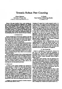
In this section, we describe space-optimal counters which are constructed using a (4,3,2)-counter where X denotes the number to be incremented. (4,3,2)-counter. Fig. 1 shows our (4,3,2)-counter obtained through brute force search which represents numbers from 0 . . . 15. Assuming the number is of the
b0
b0
b1
b2
b3
b3
b1
b1 b3
b2
b2 b3
b3
b3
100 011 110 010 010 000 111 101
110 100 011 001 000 111 010 110
Increment tree
Decrement tree
1
2
1
1
1
2
0000(0) −→ 0001(1) −→ 0100(2) −→ 0101(3) −→ 1101(4) −→ 1001(5) −→ 1 1 1 1 1 2 1100(6) −→ 1110(7) −→ 0110(8) −→ 0111(9) −→ 1111(10) −→ 1011(11) −→ 1 1 1 2 1000(12) −→ 1010(13) −→ 0010(14) −→ 0011(15) −→ 0000(0) Fig. 1: Sequence generated by the (4,3,2)-counter and increment and decrement trees
form b3 b2 b1 b0 , the corresponding increment and decrement trees for the (4,3,2)counter are shown in Fig. 1. For any internal node corresponding to bit bt , the left edge corresponds to bt = 0 and the right edge corresponds to bt = 1. The leaf nodes contain information about the new values for the bits read and the modified bits are shown underlined in the tree and the text. As an example, for the fifth leaf node from the left in the increment tree, old b0 b2 b1 = 100 and new b0 b2 b1 = 010. To increment 9, for example, we take its representation 0111 and go through the path b0 b2 b3 = 110 in the increment tree to reach the seventh leaf node; so the new values are b0 b2 b3 = 111 and the new number is 1111 which represents 10 (ten). To decrement 9, we go through the path b0 b2 b3 = 110 in the decrement tree to reach the seventh leaf node; so the new values are b0 b2 b3 = 010 and the number is 0110 which represents 8. Theorem 1. There exists a representation of integers of dimension 4 with efficiency 1 that supports increment and decrement operations with BR = 3 and BW = 2 in the worst-case. On average, an increment/decrement requires BR = 3 and BW = 1.25. 2.1
Constructing (n, n − 1, 3)-counter using (4,3,2)-counter
We can now construct an n-bit space-optimal counter for n ≥ 4 by dividing the code for a number X into two sections X(4,3,2) and XG of length 4 and n − 4 respectively where X(4,3,2) uses the above-mentioned (4,3,2)-counter representation and XG uses the Gray code [3], that is a (n − 4, n − 4, 1)-counter. To increment X, we first increment XG and then check if it represents 0 (which is possible since we read all bits of XG ). If XG is 0, then we increment X(4,3,2) . In the worst-case, this requires n − 4 reads and 1 write to increment XG and then
r 1 2 3 4 5 1 2 4 1 3 1 ⊥ ⊥ ⊥ ? +1 1⊥⊥ +1 1⊥ + 2⊥⊥⊥ ? + 2⊥⊥ + w2⊥ + w w 3 ⊥ ⊥ ⊥ +2 + 3⊥⊥ + 3⊥ + 4⊥⊥⊥ + + 4⊥⊥ + 5⊥⊥⊥ + + Fig. 2: Exhaustive search results for (n, r, w)-counter for n = 3, 4 and 5 respectively r 2 ⊥ ⊥ ⊥
r 3 ⊥ +2 + +
3 reads and 2 writes to increment X(4,3,2) , providing us with n − 1 reads and 3 writes overall. XG is represented using RPGC where incrementing or decrementing a code of dimension n requires 6 log n average number of reads (although [1, Theorem 2] considers only generating the next code, i.e., increment operation, one can verify that the same analysis holds for the decrement operations as well). The worst-case and hence the average number of writes to increment or decrement a number using RPGC is 1. Since the average number of reads and writes for X(4,3,2) are 3 and 1.25 respectively, and we increment/decrement X(4,3,2) only in one out of every 2n−4 codes, the average number of reads and writes are 6 log(n − 4) + 3/2n−4 and 1 + 1.25/2n−4 respectively. Theorem 2. There exists a representation of integers of dimension n ≥ 4 with efficiency 1 that supports increment and decrement operations with BR = n − 1 and BW = 3 in the worst-case. On average, an increment/decrement requires BR = 6 log(n − 4) + O(2−n ) and BW = 1 + O(2−n ). To the best of our knowledge, this is the first space-optimal counter with BR strictly less than n. Exhaustive search results We used exhaustive search to find (n, r, w)counters for small values of n. The results are shown in Fig. 2 for n = 3, 4 and 5 respectively. For a combination of n, r and w, a ‘⊥’ shows that no counter exists and a ‘+’ refers to its existence. A superscript of 1 shows that this is a Gray code while 2 refers to Theorem 2. A ‘?’ shows that the existence of counters remains unknown for the corresponding (n, r, w) value. An enclosed value shows that no counters were found by our brute-force search.
3
Redundant counters with increment
To reduce the number of bits read exponentially, counters with space-efficiency less than one have been considered [1, 4]. In this section, we discuss redundant counters which show better results and trade-offs for bits read and written and use these in Section 5 to obtain representations that support addition and subtraction efficiently. 3.1
Counters with one bit redundancy
To represent numbers from 0 . . . 2n − 1, we select n + 1 bits. A number X represented by xn xn−1 . . . x1 x0 consists of a carry bit S = x0 , a lower block XL
Previous New ` S xp S xp = `max 0 x 1 x < `max 0 x 0 x < `max 1 0 0 1 < `max 1 1 1 0 Table 3: Transition Table for the increment step where ` = Val(XL ) and p = log n + `. Underlines show the changed bits and x represents ‘don’t care’ condition
of the log n bits xlog n . . . x1 and the upper block XH of the last n − log n bits. p = log n + ` is a location in XH where ` refers to the value represented by XL . This is used to perform a delayed addition of the carry as explained below. We use Gray codes for representing the numbers in XL so that increment writes only one bit. The block XH is represented using SBC. The value of X is given by (`+(Val(XH ) + 2` · S)·2|XL | ) mod 2n . We determine the number of bits read and written in the worst-case by finding the maximum values of BR and BW respectively. The increment step is summarised in Transition Table 3. Increment: XL and S are read at every step, therefore BR is at least log n + 1. S = 1 implies that the carry needs to be propagated and we will read one bit from XH , whereas S = 0 implies no carry propagation and we do not need to access XH . If ` > n − log n, we reset S to 0. The different cases for increment are described below: Case 1. S = 0 and XL contains its largest value (100 . . . 0 in Gray code): This implies that a new incremental increment of XH should be initiated. Increment XL and set the carry bit S to 1. (BR = log n + 1, BW = 2) Case 2. S = 0 and XL is any other value: Increment XL . (BR = log n + 1, BW = 1) Case 3. S = 1 and xp = 1: Propagation of carry. Change xp to 0. Increment XL .(BR = log n + 2, BW = 2) Case 4. S = 1 and xp = 0: Final bit flip in XH . Change xp to 1, S to 0 and increment XL . (BR = log n + 2, BW = 3). The average number of reads to increment XL is O(log log n). The bit S is read at every step and it is set to 1 on the average 2 out of every n steps. When S = 1, we also need to read O(log n) bits to find Val(XL ). Thus the average number of bits read is O(log log n). The average number of writes can be shown to be 1 + O(n−1 ). Hence we have the following theorem. Theorem 3. There exists a representation of integers of dimension n + 1 with efficiency 1/2 that supports increment operations with BR = log n+2 and BW = 3. On average, an increment requires BR = O(log log n) and BW = 1 + O(n−1 ). 3.2
One bit read-write trade-off
We show how to modify the representations of the previous section (Theorem 3) to reduce BW from 3 to 2 by increasing BR by 1. The worst-case of BW for increment is given by Case 4 where BW = 3 since S and one bit each in XH and XL are modified. As it turns out, we can improve
Previous New ` S xp xp−1 S xp = `max 0 x − 1 x =0 1 1 − 1 0 =0 1 0 − 1 1 >0 1 x 1 0 x >0 1 0 0 1 1 >0 1 1 0 1 0 Table 4: Transition Table for the increment step for read-write trade-off where ` = Val(XL ), `max = 2|XL | − 1 and p = log n + ` + 1. Underlines show the changed bits and x represents ‘don’t care’ condition
BW further by delaying the resetting of S by one step if we read another bit. Instead of reading just one bit xp from XH when S = 1, we can read the pair (xp , xp−1 ). If the previously modified bit xp−1 = 1, then the propagation of carry is complete, else we flip the current bit xp . The only exception to this case is when XL = 0 . . . 0 which implies that p = log n + 1 which is the first position in XH . In this case, only one bit xlog n+1 is read and flipped. We modify the increment step as: Case 3. S = 1 and xp−1 = 0: propagation of carry to continue. xp−1 = 0 implies that the previous bit was 1 before getting modified. Therefore, flip xp irrespective of its value and increment XL . (BR = log n + 3, BW = 2). Case 4. S = 1 and xp−1 = 1: The previous bit was 0 before modification, hence carry has been propagated and xp is not read. Reset S to 0 and increment XL . (BR = log n + 2, BW = 2). n − log n bits
log n bits
S
log n bits
S
x x 0 1 1 1 1 1
x x 0 1 1 1 0 0
0
x x 0 1 1 1 0 0
0
x x 1 0 0 0 0 0
x x 0 1 1 0 0 0
1
x x 0 1 1 0 0 0
1
x x 1 0 0 0 0 1
x x 0 1 0 0 0 1
1
x x 0 1 0 0 0 1
1
x x 1 0 0 0 1 0
x x 0 0 0 0 1 1
1
x x 0 0 0 0 1 1
1
x x 1 0 0 0 1 1
x x 1 0 0 0 1 0
0
x x 1 0 0 0 1 0
1
x x 1 0 0 1 0 0
x x 1 0 0 1 1 0
0
x x1 0 0 1
1 0
0
(i)
(ii)
n bits
n − log n bits
(iii)
Fig. 3: Increment for a 8-bit number using (i) Standard binary counter (ii) One-bit redundant counter with BW = 3 (iii) with BW = 2. log n bits are represented using BRGC and x represents ‘don’t care’ condition
Theorem 4. There exists a representation of integers of dimension n + 1 with efficiency 1/2 that supports increment operations with BR = log n+3 and BW = 2. On average, an increment requires BR = O(log log n) and BW = 1 + O(n−1 ).
3.3
Forbidden state counter with increment
To increase the space-efficiency of the above proposed representation, we modify the data structure proposed in [1] where a particular value of t bits in a dimension n code is used as a forbidden state. A number X = xn . . . x1 consists of XH (xn . . . xlog n+t+1 ), XF (xlog n+t . . . xlog n+1 ) and XL (xlog n . . . x1 ) of n−log n−t, t and log n bits respectively. Similar to the one-bit redundant counter discussed in Section 3.1, XH and XL represent the upper and lower blocks in the number while XF acts as an alternative to the carry bit S. We use ` to refer to the value represented by XL and Fmax refers to the value 2t − 1. All the states for which Val(XF ) ≤ Fmax − 1 are considered as normal states for XF and the state where Val(XF ) = Fmax is used to propagate the carry over XH (conceptually XF = Fmax corresponds to S = 1). This representation will allow us to represent 1 − 1/2t of the 2n numbers. The block XH is represented using SBC while XF and XL are each individually represented using RPGC. Using XK to represent Val(XK ), we obtain Val(X) = XL + (XF + XH · Fmax ) · 2|XL | if XF < Fmax and Val(X) = XL + (XH + 2` ) · 2|XL | · Fmax if XF = Fmax . Increment. The increment scheme is similar to the one-bit redundant counter of Section 3.1. We first read XL and XF . If XF 6= Fmax , we increment XL . If XL now becomes 0, we also increment XF . For the case XF = Fmax , XL is used to point to a position p in XH . If the bit xp at position p is equal to 1, it is set to 0 and XL is incremented to point to the next position in XH . This corresponds to the increment scheme in the one-bit redundant counter when S is set to 1. If XL now equals n − log n − t, then we incremement XF (to set XF = 0 and terminate the propagation of carry). On the other hand, if the value of bit xp is 0, then we set xp to 1 and XF is incremented to the next value (which represents state XF = 0. This corresponds to the carry bit S being set to 0 in Section 3.1. This scheme gives a representation with BR = log n + t + 1 and BW = 3. Similar to Section 3.2, we can also obtain a representation with BR = log n+t+2 and BW = 2 by reading xp−1 . The average number of reads and writes to increment the log n bits in XL are O(log log n) and 1 respectively. The average number of reads and writes to increment XF are O(log t) and 1 respectively. Since XF is incremented once in every n steps, this adds only o(1) to the average number of reads and writes. Similarly, incrementing XH also takes o(1) reads and writes on average. In addition, at every step we need to check if Val(XF ) is equal to either Fmax or Fmax − 1 which requires an average of O(1) reads, and finally the cost of reading XL to find p on average costs at most O( 21t n1 log n). Thus we have the following theorem. Theorem 5. Given two integers n and t such that t ≤ n − log n, there exists a representation of an integer of dimension n with efficiency 1 − O(2−t ) that supports increment operations with BR = log n + t + 1 and BW = 3 or BR = log n + t + 2 and BW = 2. On average, an increment requires BR = O(log log n) and BW = 1 + O(n−1 ).
4
Counters with increment and decrement
To support decrement operations interleaved with increment operations, we modify the representation of a number X described in Section 3.1 as follows: a number X = xn . . . x1 x0 consists of an upper block XH (xn . . . xlog n+2 ), a lower block XL (xlog n+1 . . . x1 ) and the bit S = x0 which is used as either a carry bit or a borrow bit. We further split the lower block XL into two parts: an indicator bit I which consists of the bit xlog n+1 and a pointer block XP consisting of the remaining log n bits. When the indicator bit I is set to 0, S is interpreted as a carry bit, and when the indicator bit is 1, then S interpreted as a borrow bit. The log n bits in XP are used to point to a location in XH to perform a delayed carry or borrow. We use BRGC for representing XL so that an increment or decrement writes only one bit. The block XH is represented using SBC. Since XL is represented using BRGC, when Val(XL ) < 2|XP | , the indicator bit I is equal to 0 and I is equal to 1 otherwise. When I = 1, incrementing block XL corresponds to decrementing the block XP (unless XP = 0) due to the reflexive property of BRGC [3]. We use these observations in our algorithms for increment and decrement. The main ideas behind the representation and the increment/decrement algorithms are as follows: when the carry bit S is not set, we perform the increment/decrement in the normal way by incrementing/decrementing XL . When S = 0, Val(XL ) = 2log n+1 − 1 and we perform an increment, we set the bit S and reset the block XL to 0 . . . 0. Since I is now set to 0, S will be interpreted as a carry bit untill it is reset again. Similarly, when S = 0, Val(XL ) = 0 and we perform a decrement, we set the bit S and decrement XL to 2log n+1 − 1. Since I is now set to 1, S will be interpreted as a borrow bit. To increment X when the carry bit is set, we perform one step of carry propagation in XH , and then increment XL . If the propagation finishes in the current step, then we also reset the bit S to 0. To decrement X when the carry bit is set, we first decrement XL and “undo” one step of carry propagation (i.e., set the bit xp in XH to 1). Note that the when performing increments, the carry propagation will finish before we need to change the indicator bit from 0 to 1 (as the length of XH is less than 2log n ). The increment and decrement algorithms when the borrow bit are set are similar. The increment and decrement algorithms are described in the Transition Table 5. Since we read XL , S and at most one bit in XH , the read complexity BR = log n + 3. Since we change at most one bit in each of XL , XH and S, the write complexity BW = 3. The above scheme requires O(log n) average number of reads as XL is represented using BRGC and incrementing it requires O(log n) reads. To get better average-case bounds, we can represent XP using RPGC. This increases the number of worst-case writes by 1 as now I and XP are incremented independently. Thus we get a structure with BR = O(log log n) and BW = 1 + O(n−1 ) on the average but in the worst-case BW = 4.
Increment New Comments S S I xp xp−1 0 0 1 x x Increment XL (sets I) 0 1 0 x x Increment XL (resets XL ), Set S 0 0 x x x Only increment XP 1 0 0 - x (Position p beyond n) Reset S 1 0 0 1 x (Last step of carry propagation) Reset S 1 1 0 0 x (Carry propagation) 1 1 1 x 0 Undo previous borrow 1 − − − − Does not occur Decrement 0 = 0 0 x x 1 1 x x Decrement XL , Set S 0 = 0 1 x x 0 0 x x Decrement XL (Resets I) 0 > 0 x x x 0 x x x Only decrement XP 1 > 0 1 - x 0 1 - x (Position p beyond n) Reset S 1 > 0 1 0 x 1 1 1 x (Borrow Propagation) 1 > 0 1 1 x 0 1 0 x (Last step of borrow propagation) Reset S 1 > 0 0 x 0 1 0 x 1 Undo previous carry 1 > 0 0 x 1 − − − − Does not occur Table 5: Transition Table for the increment-decrement counter. For increment, new p = p + 1 and for decrement, new p = p − 1. x represents ‘don’t care’ condition and shows that the value does not exist. ` = Val(XP ), p = log n+`+1 and `max = 2|XP | −1. Underlines show the modified values Previous ` I xp xp−1 = `max 0 x x = `max 1 x x < `max x x x < `max 0 - x < `max 0 0 x < `max 0 1 x < `max 1 x 1 < `max 1 x 0
Theorem 6. There exists a representation of integers of dimension n + 1 with efficiency 1/2 that supports increment and decrement operations with BR = log n + 3 and BW = 3. On average, an increment/decrement requires BR = O(log log n) and BW = 1 + O(n−1 ). We can extend the result of Theorem 5 to support decrement operations using an indicator bit as described in Section 4. Corollary 1. Given two integers n and t such that t ≤ n − log n, there exists a representation of an integer of dimension n with efficiency 1 − O(2−t ) that supports increment and decrement operations with BR = log n + t + 2 and BW = 3. On average, an increment/decrement requires BR = O(log log n) and BW = 1 + O(n−1 ).
5
Addition and Subtraction
In this section, we give a representation for integers which supports addition and subtraction operations efficiently. A number N is said to have a span n if it can take values in the range [0, . . . , 2n − 1]. Munro and Rahman [4] gave a representation that uses n + O(log2 n) bits to represent a number N of span n, and supports adding/subtracting a M of span m to/from N in O(m + log n) time. We improve the space to n + O(log n) bits while maintaining the operation
time. We describe the data structure and scheme for addition and introduce suitable modifications to support subtaction as well. We divide the representation of the number into k = O(log n) blocks: B1 , B2 , . . . , Bk with b1 , b2 , . . . , bk bits respectively, where b1 = 2 and for 2 ≤ i ≤ k, bi = 2i−1 (if n is not a power of 2, then the last block has size bk = n − 2blog nc instead of 2k−1 ). Note that the block sizes satisfy the propPi erty that j=1 bj = 2i = bi+1 , for 1 ≤ i ≤ k − 2. Each block Bi is maintained using the increment counter of Section 3.1 using bi + 1 bits and a constant number of flag bits as described below. Hence, a number is represented using k blocks of sizes b1 , b2 , . . . , bk bits along with O(k) additional bits. The value of Pk the representation is Val(B1 ) + i=2 Val(Bi ) · 2bi . Thus the overall space used is n + O(k) = n + O(log n) bits. We now describe the modifications to the increment counter described in Theorem 3. Let X be the counter to be incremented. We introduce two additional bits max and VH . The bit max indicates whether X represents its maximum value. Assuming p = Val(XL ) represents a position in XH , VH (verifier for block XH ) = 1 if all positions in XH from 0 . . . p are 1. By this definition, when p points to any location beyond XH and VH = 1 then XH represents its maximum value. In Section 3.1 we used p to point to a location in XH only when S = 1 but now we use p as a pointer in all steps. When S = 1, we perform the delayed increment in XH and when S = 0, we read the bit xp and use it to set/reset VH . VH is set to 0 if xp = 0. If VH = 0, then we set it to 1 if S = 1 and xp = 0. This case happens when XL = 0 . . . 0 for a delayed increment. The bit max is set to 1 when VH = 1 and XL represents its maximum value. When X represents its maximum value, max = 1, VH = 1 and S = 0. Incrementing the maximum value of X sets S = 1, max = 0 and resets XL to its minimum value. The bit VH = 1 is maintained till S is reset to 0, i.e. throughout the delayed increment process. We represent every block Bi using the above modified counter. To add Pi−1 PiM to N , for some m ≤ n, we first find the largest i such that j=1 bj < m ≤ j=1 bj (i.e., bi < m ≤ bi+1 ). We add M to the number represented by the first i blocks of N in O(m) time. If any of the first i blocks has a carry bit set, then we first perform the necessary work and reset the carry bit in the block, and if necessary propagate the carry to the next block. If there is a carry from Bi to Bi+1 , we propagate this by modifying the bit maxj of the successive blocks until we find the first block Bj such that maxj is set to 0, and increment Bj , altogether in O(log n) time. The total running time is O(m + log n) since incrementing the block and propagation of the carry take O(log n) time each. The read and write complexities of the addition algorithm can be shown to be O(m + log n) and O(m) respectively. Since incrementing a counter of span n has a Ω(log n) lower bound for the read complexity, these bounds are optimal. To support subtraction, we use the increment/decrement counter of Theorem 6 to represent each block, along with additional bits to check for the maximum and minimum values of a number. The details shall be provided in the extended version. M can be subtracted from N in O(m + log n) time similarly,
since the representation of a block supports both increment and decrement operations in O(log b) time, where b is the length of the block. Theorem 7. An integer of span n can be represented by a data structure which uses n + O(log n) bits such that adding or subtracting an integer of span m can be perfomed by reading O(m + log n) bits and writing O(m) bits.
6
Conclusion
We have shown that a number of dimension n can be incremented and decremented by reading strictly less than n bits in the worst-case. For an integer in the range [0, . . . , 2n −1] represented using exactly n bits, our (n, n−1, 3)-counter reads n − 1 bits and writes 3 bits to perform increment/decrement operations. One open problem is to improve the upper bound of n − 1 reads for such spaceoptimal counters. Fredman [2] has shown that performing an increment using BRGC requires n bits to be read in the worst-case but the same is not known for all Gray Codes. For the case of redundant counters, we have improved the earlier results by implementing increment operations using counters with space-efficiency arbitrarily close to one which write only 2 bits with low read complexity. We have obtained representations which support increment and decrement operations with fewer number of bits read and written in the worst-case and show trade-offs between the number of bits read and written in the worst-case and also between the number of bits read in the average-case and the worst-case. Finally we have also improved the space complexity of integer representations that support addition and subtraction in optimal time.
References 1. Prosenjit Bose, Paz Carmi, Dana Jansens, Anil Maheshwari, Pat Morin, and Michiel H. M. Smid. Improved methods for generating quasi-gray codes. In Haim Kaplan, editor, SWAT, volume 6139 of Lecture Notes in Computer Science, pages 224–235. Springer, 2010. 2. Michael L. Fredman. Observations on the complexity of generating quasi-gray codes. SIAM Journal on Computing, 7(2):134–146, 1978. 3. F. Gray. Pulse code communications. U.S. Patent (2632058), 1953. 4. M. Ziaur Rahman and J. Ian Munro. Integer representation and counting in the bit probe model. Algorithmica, 56(1):105–127, 2010.