drawing andfree-form skeleton object drawing are the most ... parameterized outline drawing technique. .... the joints of a poly-line, we draw another quad.
Integrating 2%-D Computer Animation Techniques for Supporting Traditional Animation Frank Van Reeth Expertise Centre for Digital Media Limburg University Centre Belgium techniques in order to realize a system in which the creation of animated characters and scenery with a look alike the one traditionally encountered in comic strip-books. Hence, we opted for a 2%-D approach, in which 2D characters and scenery can freely be positioned in the 3D space. Hence, the object modeling tools provided are two-dimensional in nature, while the position specification for nonmoving items and the motion specification for moving items are three-dimensional in nature. Other 2%-D computer animation systems reported upon in literature, are Inkwell [6] and COSA [7]. A main difference with Inkwell is to be found in offered functionality and the available tools to come to this functionality: e.g., in Inkwell, warped Coons' patches are a fundamental primitive in free-form animation specification, whereas RUFIAS utilizes for this an approximated dynamic motion specification on skeletons around which free-form objects are placed. Another main difference is to be found in the fact that RUFIAS utilizes a 3D space to animate the 2D objects. The main difference with COSA (also implemented in our Lab) is the fact that COSA is designed to be used in cut-out shape animation in which rigid 2D -mostly textured- polygons are used in the object representation, whereas RUFIAS uses fi-ee-form object representations. Regarding the motion specification, e.g., COSA does not support the approximated A main dynamic motion specification. difference between RUFIAS and both other systems is to be found in the provided parameterized outline drawing technique. In Section 2, an overview is given of the RUFIAS system. Section 3 elaborates on the
Abstract This paper is about a 2%-D animation system, termed RUFIAS @om Rubbery dnimation System), that is utilized for the creation of computer animation sequences which have the look and feel of traditional hand-drawn animation productions. RUFIAS provides a user interface where various basic methods of animation specijication are provided, of which an approximated dynamic motion Specification technique and motion curve based animation are the most important, and where various character drawing metho& are provided, of which parameterized outline drawing andfree-form skeleton object drawing are the most important. RUFIAS is implemented on state-of-the-art graphics workstations, allowing an interactive (as well as real-time) creation of animation sequences by means of direct manipulation.
1: Introduction Since the early days of computer animation [l], many techniques have been reported upon that improve or facilitate the creation of animated sequences[21,[31,[41. A large part of the later techniques and methods described in literature, is mostly aimed at 3D computer animation and a trend towards realtime Virtual Reality based approaches for animation specification can be noticed [SI. With the design and implementation of RUFIAS, the main goal was to utilize and extend some of these computer animation
1087-4844/96 $5.00 0 1996 IEEE
118
Authorized licensed use limited to: Communication University of China. Downloaded on December 6, 2009 at 06:10 from IEEE Xplore. Restrictions apply.
parameterized outline functionality of RUFIAS. Sections 4 and 5 elucidate resp. the concept of animated stick-figure skeletons and the construction of free-form objects around
these skeletons. These various sections give some examples. Conclusions and directions for future work are given in Section 6 .
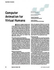
Figure 1 : Example scenery
2: Overview of the RUFIAS System
main goal of our implementation is the creation of animated 2%-D characters and scenery in a 3D space (viewed upon by a three-dimensional virtual camera), with a look
RUFIAS is implemented in OpenGL on an SGI ONYX. As mentioned before, the
119
Authorized licensed use limited to: Communication University of China. Downloaded on December 6, 2009 at 06:10 from IEEE Xplore. Restrictions apply.
Figure 2: Free-form Object and Skeleton editor skeletons reported upon in Section 5 . The animation of this character is govemed by the approximated dynamic simulation technique for interactive motion specification reported upon in [8] and shortly described in Section 4. A snapshot of the editor for this functionality is given in Figure 2. We will come back to this in Section 4. In order to have a fall back position for animation specification which currently falls out of the scope of the aforementioned tools, the possibility is offered in which objects can be texture mapped with hand-drawn bitmap sequences. By mapping the hand-drawn bitmaps onto hierarchically modeled characters, additional functionality is offered. The motion specification in these cases is supported by a curve editor infrastructure (all degrees of freedom and parameters in the animation are represented in time by interactively editable piece-wise continuous Bezier-curves) that is traditionally utilized in 3D animation systems. The knight in the snapshot of Figure 1 is an example of this.
and feel alike the one encountered in traditional 2D animation and comic stripbooks. In Figure 1, some illustrations of this are given. The two main techniques reported upon in this paper have been utilized in these animation snapshots: 0 The outlines in the modeled figures (the trees, the castle, the mountains, etc.) have been rendered with the parameterized outline technique described in Section 3. This outlining technique allows animators to change in time a number of parameters on control points of the outlines at issue. The main parameters involved are the color, the width and the visibility of the outline. The alteration of the outline width in time, e.g., allows the outlines to maintain their width on the screen, irrespectively of the distance the outlines have with respect to the virtual camera: outlines which have (in object space) a fixed width with respect to their corresponding object, e.g. when they are generated using texture maps, would get a larger size in on the screen when their distance to the virtual camera in the 3D world space is reduced. 0 The puppet character has been generated with the technique of free-form objects around
120
Authorized licensed use limited to: Communication University of China. Downloaded on December 6, 2009 at 06:10 from IEEE Xplore. Restrictions apply.
I
1 I
Figure 3 : Example sequence outline parameterization
3: Parameterized Outlines
parameterized. In Figure 3, an example is given of this outline parameterization. On the left, the castle’s outline width increases as the camera approaches, while on the right, the outline width remains unchanged. The parameters which can be animated are outline width, outline color and outline visibility. Each of these parameters is defined at each of the joint points of the Bezier-curves in the object outlines. When the curves are instantiated towards poly-lines, the parameter values are then copied and interpolated towards the joint points of the poly-lines. The color parameter is most of the time a fixed value for a given character, but they can be interpolated if needed. The visibility parameter indicates whether or not the curves, and ultimately the poly-lines, between jointpoints are to be drawn as outlines or not (they are not drawn if the parameters of the two surrounding joint points indicate ‘invisible’).
An interactive Bezier-curve editor allows the creation of free-form objects which can be used as basic characters or scenery for the animation sequence to be set up. The curves in the system can be open or closed; the internal area of the latter type of curves can be filled with colors. In order to have a look and feel alike of cartoon figures, it is necessary that all the characters and items in the depicted scenery are provided with (mostly solidcolored) outlines. For non-moving objects, these outlines can be generated using texture mapping. In case where the distance from the object to the virtual camera changes, however, the width of these textured outlines will change. For moving objects, this becomes even more a problem. Hence we implemented a technique in which the outlines can be
121
Authorized licensed use limited to: Communication University of China. Downloaded on December 6, 2009 at 06:10 from IEEE Xplore. Restrictions apply.
Figure 4: Geometrical aspects at the outline joints More attention is needed for the width parameter. In figure 4 we show how the poly-lines are drawn. Instead of using line-draw routines, we use quads to represent lines. Every vertex of a poly-line has a width parameter. In order to preserve the same width in the outlines, even when the poly-line is moved in the Z-direction, we calculate a new width according to the depth of the vertex. This also gives us the possibility to change the camera position and direction in the scene while the line-width stays the same. To avoid the triangular holes at the joints of a poly-line, we draw another quad over the endpoints of the current poly-line and the next one. When the poly-lines are not too thick, this methods gives reasonable results.
The adaptation of the object is computed using an iteration method. In each iteration the current configuration is checked against all constraints placed by the animator. In a frst step all length constraints are being applied to the object. If the length between to point exceeds the maximum length or is smaller than the minimum length an adaptation of the object is forced. The two points need to be moved away or towards each other. This means that the momentum of both points must be changed so that this movement takes place. In a next step all angle constraint are checked against violations, An angle constraint uses three points, i.e. a hinge and two points that form the angle. If a joint constraint is violated one of the two points forming the angle must be rotated round the hinge point. The displacement that this rotation produces can not be directly used as a change of momentum for that point. The rotation produces a torque that must be compensated. In the final step, all momentum vectors are applied to the object points. The iteration is repeated as long as there are constraints being violated or a maximal iteration count is reached. A few modifications were made to the algorithm proposed in [8]. The correction for the torque induced by the rotation of a vector round the hinge, contained some errors. To compensate the torque displacement vectors are computed for the two points. The corrected displacement vectors are (cf. [SI):
4: Animated Skeletons For the animation of objects we use a technique based on the algorithm presented in [8]. This is a approximated dynamic simulation technique for interactive motion specification. The algorithm tries to maintain the object in a correct configuration, where no length constraints or joint constraints are violated, while the user can interactively drag points of the skeleton, There are two types of constraints used to maintain the form of the object, i.e. joint constraints, and length constraints. Both types allow the user to specify a minimum and maximum value. It is up to the computer to maintain the current angle or length within this range. The use of a minimum and maximum value for constraints makes it possible for the objects to extrude. This is a frequently used technique to give cartoon figures a life-like appearance in an animation sequence.
-
chl = corr x (PI p2) ch3 = ch3 f corr x (p3 - p2) where corr = torque * ( I / ((length @I -p2))2 + (length (p3 - P2))2,,
122
Authorized licensed use limited to: Communication University of China. Downloaded on December 6, 2009 at 06:10 from IEEE Xplore. Restrictions apply.
Figure 5 : Results of the RUFIAS System we take a different approach towards the realization of free-form animation specification. The RUFIAS system works in two different modes. In the first mode, i.e. play mode, the user can drag points of the skeleton while the object moves correctly. The second mode allows the animator to design and modify the skeleton, and draw the figure to be animated. In skeleton mode the user can add, delete modify Bezier-curves. This allows the user to draw a figure using conventional curvedrawing techniques. The skeleton can be modified using the length and joint buttons. These buttons allow the user to change or add length and angle constraints. For each constraint the user can specify a minimal and maximal value. This allows the object to be of fixed shape or have an elastic shape. The animator can also change various parameters of the Bezier-curves, and skeleton, i.e. the linewidth and smoothness of the curves, the mass of the skeleton points. After drawing of the Bezier-curves constituting the free-form objects, the animators currently have to specify manually the rods of the skeleton and provide them with the
and torque = ch3 x (p3 - p2) and ch3 is the original displacement of point p 3 caused by the rotation of point p 3 round the hinge. The algorithm has also been modified towards a parallel version. The constraint checking and modification of the object based on these constraints is distributed over the number of processors available. The use of this technique makes effects like gravitation easy to implement. For gravitation the momentum of each point is initialized with the gravitation vector. We are currently finishing a wind effect where the animator can change the velocity of the wind in real time. This effect can be implemented using the same method.
5: Free-form Objects. around the Skeletons In the literature, several techniques have been reported upon that allow motion specification of free-form objects; cf. [6], [SI, [9],[IO]. In the implementation of RUFIAS,
123
Authorized licensed use limited to: Communication University of China. Downloaded on December 6, 2009 at 06:10 from IEEE Xplore. Restrictions apply.
appropriate constraints. When the object forms are becoming somewhat more complex (a few hundred of rods in the skeleton), this becomes a tiresome process. To overcome this problem, we started designing tools to allow semi-automatic creation of the skeleton structure and specification of the constraints (for larger characters, it turns out that many constraints are set to a fixed value in order to give the character stability; these kinds of constraints will be set automatically).
within the Bezier-curves of the object shapes would also be a real time-saver (cf. Section 5). Inclusion of more 3D techniques (but still retaining the current look in the resulting animation sequences) into RUFIAS will also be a topic of future research. Since real-time (or at least interactive) rendering remains possible in many situations, the road is paved for some extensions towards interactive applications outside the animation domain: interactive stories on CD-ROM,interactive TV,etc.
6: Conclusions and Directions of Future Research
7: Acknowledgements Part of this research is funded by grants from the European Fund for Regional Development and the Flemish Government. We would furthermore like to acknowledge the people at the Expertise Centre for Digital Media who have contributed in one way or another to the realization of the RUFIAS system. Especially the implementation input of David Nouls, Bruno Rassaerts and Raf Van Ham is greatly appreciated. The assistance of Koen Elens at the editorial level is greatly appreciated. Liesbeth Beckers is acknowledged for her input on the artistic level.
In this paper, we described the functionality of RUFIAS, a 2%-D computer animation system designed for the creation of animated characters and scenery with a look and feel alike the one traditionally encountered in comic strip-books. It is elucidated and illustrated how parameterized techniques can be utilized to control the outlines of the drawn objects. It is moreover explained how an approximated dynamic motion specification is used on skeletons and how free-form Beziercurves are placed to constitute the objects. RUFIAS allows the manipulation of fairly complex 2%-D animation with the intended look and feel, but many animated sequences still can not be governed by its tools; hence, a fall back position is offered by means of a curve based hierarchical motion specification in which objects texture mapped with handdrawn bitmap sequences can be animated. Several directions of future work can be indicated. A first one involves the integration of other 2D (or 2%-D) computer animation techniques, e.g., the cut-out shape animation functionality of COSA [7] and some of the warping ideas of Inkwell [6],into the concepts of RUFIAS. Some pragmatic user-interface related issues can be solved in future work as well: we have a list of pragmatic ‘feature requirements’ from the animators, mostly dealing with improvements and short-cuts in the user interface: e.g. we are finishing an implementation in which the control points of the Bezier-curves of the object shapes no longer have to be a part of the skeleton joint-points, whereas a semi-automatic generation of the skeletons and constraints on the skeletons
References [I] Burtnyk, N. and M. Wein, “ComputerGenerated Key-Frame Animation”, Journal of the
Society Motion Picture and Television Engineers, Vol. 8, NO.3 , 1971, pp. 149-153.
[2] Gomez, E.J., “Twixt: a 3D Animation System”, Proc. Eurographics’84, 1984, pp. 121-133.
[3] Magnenat-Thalmann, N. and D. Thalmann, “Computer Animation, Theory and Practise”,
Springer Verlag, Tokio Berlin Heidelberg New York, 1985.
[4] Magnenat-Thalmann, N.and D.Thalmann, “An indexed Bibliography on Computer Animation”, IEEE CG&A, Vol. 5 , No. 7,1985, pp. 76-86. [5] Thalmann, D., “Using Virtual Reality Techniques in the Animation Process”, in Earnshaw, R.A., M.A. Gigante and H. Jones “Virtual Reality Systems”, Academic Press, London San Diego New York Boston Sydney Tokyo Toronto, (2nd edition), 1994, pp.143-159.
124
Authorized licensed use limited to: Communication University of China. Downloaded on December 6, 2009 at 06:10 from IEEE Xplore. Restrictions apply.
[6] Litwinowicz, P.C., “Inkwell: a 2%-D Animation System”, Computer Graphics, Vol. 25, No. 4, 1991, pp. 113-122.
[8] van Overveld, C., “A technique for motion specification in computer animation”, The Visual Computer, Vol6, pp. 106-1 16, 1990.
[7] Coninx, K., F. Van Reeth and E. Flerackers “Interactive Specification of 2%-D Animation by Exploiting a Real-time 3D Rendering Architecture”, to be published in Proc. Eurographics UK’96, London, March 1996,8 pages.
[9] Reeves, W., “Inbetweening for Computer Animation Utilizing Moving Point Constraints”, Computer Graphics, Vol. 15, No. 3, 1981, pp. 263269. [lo] Sederberg, T.W. and S.R. Parry, “Free-Form Deformation of Solid Geometric Models”, Computer Graphics, Vol. 20, 1986, pp. 151-160.
125
Authorized licensed use limited to: Communication University of China. Downloaded on December 6, 2009 at 06:10 from IEEE Xplore. Restrictions apply.