Integrating Heterogeneous Distributed COTS. Discrete-Event Simulation Packages: An. Emerging Standards-Based Approach. Simon J. E. Taylor, Xiaoguang ...
IEEE TRANSACTIONS ON SYSTEMS, MAN, AND CYBERNETICS—PART A: SYSTEMS AND HUMANS, VOL. 36, NO. 1, JANUARY 2006
109
Integrating Heterogeneous Distributed COTS Discrete-Event Simulation Packages: An Emerging Standards-Based Approach Simon J. E. Taylor, Xiaoguang Wang, Stephen John Turner, Member, IEEE, and Malcolm Y. H. Low
Abstract—This paper reports on the progress made toward the emergence of standards to support the integration of heterogeneous discrete-event simulations (DESs) created in specialist support tools called commercial-off-the-shelf (COTS) discrete-event simulation packages (CSPs). The general standard for heterogeneous integration in this area has been developed from research in distributed simulation and is the IEEE 1516 standard The High Level Architecture (HLA). However, the specific needs of heterogeneous CSP integration require that the HLA is augmented by additional complementary standards. These are the suite of CSP interoperability (CSPI) standards being developed under the Simulation Interoperability Standards Organization (SISO—http://www.sisostds.org) by the CSPI Product Development Group (CSPI-PDG). The suite consists of several interoperability reference models (IRMs) that outline different integration needs of CSPI, interoperability frameworks (IFs) that define the HLA-based solution to each IRM, appropriate data exchange representations to specify the data exchanged in an IF, and benchmarks termed CSP emulators (CSPEs). This paper contributes to the development of the Type I IF that is intended to represent the HLA-based solution to the problem outlined by the Type I IRM (asynchronous entity passing) by developing the entity transfer specification (ETS) data exchange representation. The use of the ETS in an illustrative case study implemented using a prototype CSPE is shown. This case study also allows us to highlight the importance of event granularity and lookahead in the performance and development of the Type I IF, and to discuss possible methods to automate the capture of appropriate values of lookahead. Index Terms—Discrete-event simulation, distributed simulation, high level architecture, interoperability, standards.
I. I NTRODUCTION
D
ISCRETE-EVENT simulation (DES) is a computer-based technique typically used to model and investigate the behavior of complex dynamic systems [2], [39], [43]. Discrete event refers to the type of simulation that models a system in terms of state variables that change instantaneously at separated points in time (events) as opposed to continuous change (continuous simulation) [27]. DES techniques can be used to support system analysis, education and training, acquisition and system acceptance, research and Manuscript received December 1, 2004; revised May 20, 2005. This paper was recommended by Associate Editor M. Zhou. S. J. E. Taylor is with Brunel University, Brunel UB8 3PH, U.K. X. Wang and S. J. Turner are with the Nanyang Technological University, Singapore 639798, Singapore. M. Y. H. Low is with the Singapore Institute of Manufacturing Technology, Singapore 638075, Singapore. Digital Object Identifier 10.1109/TSMCA.2006.859167
planning, organizational change, and facilitation [36], [42] in a range of diverse areas such as commerce [7], defense [22], health care [11], manufacturing [8], supply chains [18], and civil [28] and maritime transportation [10]. We use the term commercial-off-the-shelf (COTS) discrete-event simulation packages (CSPs) to describe commercially available software tools that have been developed to facilitate the process of DES and to provide a distinction from other similar modeling approaches such as those based on Petri Nets or systems dynamics [26]. Examples of CSPs include the following: ProModel (http://www.promodel.com); Arena (http://www. arenasimulation.com); Witness (http://www.lanner.com); Extend (http://www.imaginethatinc.com); AutoMod (http://www. automod.com); and Simul8 (http://www.simul8.com). Distributed simulation can be defined as the distribution of the execution of a single run of a simulation program across multiple processors [14]. There are various motivations for this. These include the reduction of the execution time of a single simulation run, the use of multiple computers to support the memory needs of the simulation and the linking of simulations sited in different locations [15]. In terms of CSPs as described above, distributed simulation is also used for the following reasons: to integrate DESs across virtual organizations, extended enterprises, and supply chains; reduce the cost of model development by enabling the reuse of distributed model components; and protect intellectual property (information hiding in distributed models) [17], [33], [38], [44]. Additionally, variants of distributed simulation techniques can also reduce the time taken for simulation experimentation (distributed replication and experimentation) and reduce simulation project costs (remote model execution and group working) [45], [54]. Although there are excellent examples of successful distributed simulations with CSPs (in particular Boer et al. [6] and Mertins et al. [32]), a general solution to this problem of heterogeneous integration is illusive. There is a strong argument to suggest that the reason for this is that no governing standard in this area exists [52]. In general distributed simulation there is a different story. In 2000, the IEEE 1516 standard The High Level Architecture (HLA) was published [25]. This built on previous experience of the IEEE 1278 standard Distributed Interactive Simulation (DIS) [24] and provided the basis for the integration over a network (interoperation) of general heterogeneous distributed simulations. However, the specific needs of heterogeneous CSP integration require that the HLA is augmented by additional
1083-4427/$20.00 © 2006 IEEE
110
IEEE TRANSACTIONS ON SYSTEMS, MAN, AND CYBERNETICS—PART A: SYSTEMS AND HUMANS, VOL. 36, NO. 1, JANUARY 2006
complementary standards. These are the suite of CSP interoperability (CSPI) standards being developed under the Simulation Interoperability Standards Organization (SISO) by the CSPI Product Development Group (CSPI-PDG). The suite consists of several interoperability reference models (IRMs) that outline different integration needs of CSPI, interoperability frameworks (IFs) that define the HLA-based solution to each IRM, appropriate data exchange representations to specify the data exchanged in an IF, and benchmarks termed CSP emulators (CSPEs). In this paper, we contribute to the development of the Type I IF that represents the HLA-based solution to the problem outlined by the Type I IRM (asynchronous entity passing) by developing the entity transfer specification (ETS) data exchange representation. We show the use of the ETS in a case study implemented using a prototype CSPE. We also highlight the importance of event granularity and lookahead in the performance and development of the Type I IF, and discuss methods to automate the capture of appropriate values of lookahead. The paper is structured as follows. Sections II and III introduce the background to our work, CSPs and the HLA and its approach to heterogeneity. Section IV discusses our emerging standards-based approach introduced by the CSPI-PDG. The problem outlined by the Type I IRM (asynchronous entity passing) is presented. Within this context, the main contribution of this paper, the ETS, a data exchange representation intended to support entity transfer is developed. Section V presents an illustrative case study implemented in our version of a type I CSPE to demonstrate how the ETS is intended to be used in the Type I IF. The section also presents results from experimentation to highlight the role of event granularity and lookahead in the Type I IF. Section VI discusses these results and possible methods to automate the capture of appropriate values of lookahead in the Type I IF. Section VII concludes the paper with some reflections on our standards-based approach and the future directions of this work. II. H ETEROGENEOUS CSP S Visual interactive simulation has played an important role in DES for around 25 years [3], [4], [23]. Today, these have evolved into CSPs. These DES support environments use visual programming approaches that allow simulation modelers to build discrete-event models using drag and drop interfaces and provide a range of facilities for DES [e.g., two-dimensional (2-D)/three-dimensional (3-D) animation and visualization, replication control, experimentation and statistical analysis utilities, optimization support, etc.] There are around 30 of these CSPs available commercially [50]. All support DES in that each CSP supports the building of models that change state at events. Generally, such DES models are typically composed of networks of alternating queues and activities that represent, for example, the series of buffers and operations composing a manufacturing system. Entities, consisting of sets of typed variables termed attributes, represent the elements of the manufacturing system undergoing machining. Entities are transformed as they pass through these networks and may enter and exit the model at specific points. Additionally, activities may compete for resources that represent, for example, the operators of the
machines. To simulate a model, a CSP will typically have a simulation executive, an event list, a clock, a simulation state, and a number of event routines. The simulation state and event routines are derived from the simulation model. The simulation executive is the main program that (generally) simulates the model by first advancing the simulation clock to the time of the next event and then performing all possible actions at that simulation time. For example, this may change the simulation state (e.g., ending a machining activity and placing an entity in a queue) and/or schedule new events (e.g., a new entity arriving in the simulation). This cycle carries on until some terminating condition is met. Virtually every CSP is based on a variant of a simulation world view. A world view, or conceptual framework, is “. . . a structure of concepts and views under which the simulationist (developer) is guided for the development of a simulation model” [1]. The most well-known of these are event scheduling, activity scanning [9], the three-phase approach [58], and process interaction. In the 1960s, these gave rise to simulation programming languages such as GPSS, SIMAN, SIMSCRIPT, SIMULA, and SLAM. Many of these were the predecessors to the CSPs used today [35]. CSPs also have widely differing terminology, representation, and behavior [46]. For example, an entity in one CSP may be termed as an item and in another object. In one CSP, the data types might be limited to integer and string, while in another, the data types might include those found in any object-oriented programming language. The same observations are true for the other model elements of queue, activity, resource, and entry and exit points. Behavior is also important as the set of rules that govern the behavior of a network of queues and activities subtly differ between CSPs (e.g., the rules that govern behavior when an entity leaves a machine to go to a buffer). Indeed, even the representation of time can differ. This is also further complicated by variations in model elements over and above the “basic” set (e.g., transporters, conveyors, flexible manufacturing cells, robots, etc.) The result of this is that it is entirely plausible to argue that there are now as many world views as there are CSPs. With our goal of developing distributed DES tools, this degree of heterogeneity presents a substantial challenge. We now introduce distributed simulation and our standards-based approach to the issue of heterogeneity in this field. III. IEEE 1516 HLA A. HLA and Heterogeneity The IEEE 1516 standard HLA [25] is a general standard for the heterogeneous integration of distributed simulations. This and its predecessor, the IEEE 1278 standard DIS [24], both came from the need of the U.S. Department of Defense (DoD) to reduce the cost of training military personnel by reusing computer simulations linked via a network, i.e., through the creation of distributed simulations of real-time military applications. The DIS standard described the format of data exchanged by simulators linked together over a network for military applications. The limited domain of DIS (military and real-time applications) and technical problems, such as time management
TAYLOR et al.: INTEGRATING HETEROGENEOUS DISTRIBUTED CSPs: AN EMERGING STANDARDS-BASED APPROACH
and limited bandwidth, led to the creation of the HLA. In the HLA, a distributed simulation is called a federation, and each individual simulator (in our case, the combination of a CSP and its model) is referred to as a federate. An HLA runtime infrastructure (RTI) provides for federates to interact with one another, as well as to control and manage the simulation. The HLA is composed of four parts, namely: 1) a set of rules; 2) the object model template (OMT); 3) the federate interface specification (FIS); and 4) the federate development process (FEDEP). The rules are a set of ten basic conventions that define the responsibilities of federates and their relationship with the RTI. The FIS is an application interface standard for distributed simulation middleware, which defines how federates interact within the federation, and is implemented by an RTI. The OMT provides a common presentation format for HLA federates. Using the OMT, each federate defines, in its simulation object model (SOM), the data that it is willing to share (publish) with other federates and the data it requires from other federates (subscribe). The federation object model (FOM) combines the federate SOMs into a single object model for the federation and defines the overall data to be exchanged (published and subscribed) between federates. The FEDEP defines the recommended practice processes and procedures that should be followed by users of the HLA to develop and execute their federations. Federates do not communicate with one another directly. Instead, they exchange information using only the services provided by the RTI. Each federate has an RTI ambassador and a federate ambassador. A federate invokes an operation on the RTI ambassador whenever it needs an RTI service (e.g., a request to advance simulation time). In the reverse direction, the RTI invokes an operation on the federate ambassador whenever it needs to pass data to the federate (e.g., to inform the federate that the request to advance simulation time has been granted). Thus, operations in the federate ambassador need to be implemented by the federate, as part of the federate code or as part of some interface service. An RTI provides six classes of services. 1) Federation management: These services allow federates to create and destroy federation executions, and join or resign from an existing federation. 2) Declaration management: These services allow federates to publish federate data and to subscribe to updated data produced by other federates. 3) Object management: These services allow federates to create and delete object instances, and produce and receive data. 4) Ownership management: These services allow federates to transfer the ownership of object data during the federation execution. 5) Time management: These services coordinate the advancement of simulation time of the federates. 6) Data distribution management (DDM): These services can reduce unnecessary information transfer between federates by filtering out irrelevant data. This overcame the shortcomings of DIS by being simulationdomain neutral (the OMT) and specifying functionality for time
111
management and bandwidth control (in the FIS modules). In terms of heterogeneity, the HLA, therefore, provides facilities to describe any data exchange format as required. Specifically, the OMT provides neutral data representation types that are mapped to/from the RTI. These are the basic representation types of HLAinteger16/32/64BE/LE, HLAfloat32/64BE/LE, HLAoctetPairBE/LE, and HLAoctet (16/32/64 represents bit size and BE/LE represents big/little endian representation), the simple data representation types of HLAASCIIchar, HLAunicodeChar, HLAbyte, and user-defined enumerated types (including HLAboolean represented as an HLAinteger32BE with possible values of 0 and 1), the array data type representation types of HLAASCIIstring, HLAunicodeString, HLAopaqueData (uninterpreted), and user-defined array types, user-defined fixed record data types, and user-defined variant record data types. The OMT also provides 14 tables to define various aspects of the SOMs and FOM of a distributed simulation using the HLA. 1) Object model identification table: This associates important identifying information with an HLA object model (SOM/FOM). 2) Object class structure table: This records the namespace of all federate or federation object classes and describes their class–subclass relationships. 3) Interaction class structure table: An interaction is a type of data exchange that models “(a)n explicit action taken by a federate that may have some effect or impact on another federate within a federation execution.” This table records the namespaces of all federate or federation interaction classes and describes their class–subclass relationships. 4) Attribute table: An attribute is a type of data exchange that models “(a) named characteristic of an object class or object instance” and is semantically different to attributes mentioned in Section II. This table specifies the object attributes in a federate or federation that can be exchanged. 5) Parameter table: This specifies the parameters of interaction classes in a federate or federation. 6) Dimension table: This specifies the dimensions used to filter instance attributes and interactions (used in DDM). 7) Time representation table: This is used specify the common representation of time values (including lookahead—see Section IV). 8) User-supplied tag table: This specifies the representation of tags used in HLA services. 9) Synchronization table: This specifies the representation and data types used in HLA synchronization services (typically used to synchronize the federation at the start and end of the simulation). 10) Transportation type table: This table describes the transportation mechanisms used in the federation (essentially following UDP and TCP semantics). 11) Switches table: This specifies the initial settings for parameters used by the RTI. 12) Data type table: This specifies details of data representation in the object model (as described above).
112
IEEE TRANSACTIONS ON SYSTEMS, MAN, AND CYBERNETICS—PART A: SYSTEMS AND HUMANS, VOL. 36, NO. 1, JANUARY 2006
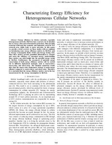
Fig. 1. Simple distributed simulation.
13) Notes table: This table expands explanations of any OMT table item as required. 14) FOM/SOM lexicon: This defines all of the objects, attributes, interactions, and parameters used in the HLA object model. We shall return to both the OMT and FIS in the next section as we present our emerging standard to support the integration of heterogeneous distributed CSPs with HLA. IV. I NTEGRATING H ETEROGENEOUS D ISTRIBUTED CSP S AND THE HLA: A S TANDARDS -B ASED A PPROACH A. Previous Work Although initial work on the use of the HLA to integrate heterogeneous distributed CSPs can be traced back to pioneering work done by Straßburger in the late 1990s [47], this area is still emerging [52]. Research has mainly focussed on technological challenges using combinations of various CSPs and HLAbased and non-HLA-based approaches. Mertins et al. [32], Rabe and Jäkel [40], [41], Hibino et al. [19], McLean and Riddick [34], and Linn et al. [30] discuss the use of the HLA and the associated adapter technologies of the MISSION project to support the distributed simulation of manufacturing systems. Lendermann et al. [29] and Straßburger et al. [48] also discuss strategies for HLA use in the same domains. In terms of non-HLA approaches, the following contributions have been made. Taylor et al. [54], [55] discuss the use of the generic runtime infrastructure for distributed simulation (GRIDS) to support the distributed simulation of supply chains and automotive engine production. Fujii et al. [12] present an approach to the distributed simulation of virtual factories. Zülch et al. [61] show how distributed simulations of manufacturing systems can be composed hierarchically. Gan et al. [17] compare HLA against an MPI-based implementation extended from the protocol described in [16]. Boer et al. [6] discuss the use of distributed simulation to link to real-time data sources using the first all modes all sizes (FAMAS) backbone and use the same technology to support the distributed simulation of a port. All of these approaches are largely incompatible due to the format of the data exchanged between federates and the protocol used to perform the exchange, and the type of simulation information exchanged.
B. Heterogeneous Distributed CSP Integration Problem In our discussion, a distributed simulation (federation) is composed of CSPs and their models (federates) that exchange data (interactions and/or attributes) via an RTI in a timesynchronized manner. Consider the simple distributed simulation of Fig. 1. Two factories F1 and F2 interact in various ways as denoted by the black double-headed arrow. Each model consists of an arrival source Soi, a queue Qi, a workstation Wi, a resource Ri, and an exit sink Sii (where i is the factory identifier). There are various types of model information that we might share. For example, entities might be passed between models (i.e., the two factories are linked together—entities leave F1 at Si1 and arrive in F2 at So2) and the resources R1 and R2 might be shared to reflect a shared set of operators that can operate workstations W1 and W2. Factory F1 must, therefore, publish and send information to the RTI in an agreed format and time-synchronized manner and factory F2 must subscribe to and receive that information in the same agreed certain format and time-synchronized manner, i.e., both federates must agree on a common representation of data and both must use the RTI in a similar way. Further, the “passing” of entities and the sharing of resources require different distributed simulation protocols. In entity passing, the departure of an entity at a sink and the arrival of an entity at a source is effectively the same scheduled event in the two models—most distributed simulations represent this as a timestamped event message sent from one federate to another [6], [49]. The sharing of resources cannot be handled in the same way. For example, when resource (R1) is released or an entity arrives in queue Q1, a CSP executing the simulation of F1 will determine if workstation W1 can start processing an entity. If resources are shared, each time R1 or R2 changes state, a timestamped communication protocol is required to inform and update the changes of the shared resource state [31]. Our heterogeneous distributed CSP integration problem, therefore, consists of several parts, namely: What are the synchronization demands of data exchanged between federates, how should these be implemented through the RTI, what format should the data take, and what relationship should this have to the CSPs and their models? While the citations for past work go some way to solving these problems, these are incompatible.
TAYLOR et al.: INTEGRATING HETEROGENEOUS DISTRIBUTED CSPs: AN EMERGING STANDARDS-BASED APPROACH
Fig. 2.
Type I IRM.
In an attempt to solve this, we now present our emerging standards-based approach. C. Emerging Standards and the CSPI-PDG In August 2002, the HLA COTS Simulation Package Interoperability Forum (HLA-CSPIF) was created in an attempt to produce a generalizable solution to the problem of distributed heterogeneous CSP integration. Over 2 years, discussions led by the forum resulted in the splitting up of the integration problem into different requirements. The rationale is this. If we consider all possible distributed simulation requirements in this area, three important observations can be made, namely: 1) not all distributed simulations need all integration approaches; 2) some integration approaches are relatively straightforward and some are extremely complex; and 3) not all integration requirements are known. In the simple example of Fig. 1, some distributed simulations only require entities to be passed between them. The problem of entity passing is somewhat simpler than synchronous shared state in the case of resource sharing. The issue of not being able to know all integration requirements has been demonstrated by the experiences of the forum. Entity passing and resource sharing were the first requirements that were identified. However, the requirements to integrate models with shared (global) events, various data structures, and conveyors were later identified by members. It is expected that as simulation modelers use distributed simulation, more requirements will emerge. The above requirements have been encapsulated into (currently) six IRMs [51]. These are: 1) 2) 3) 4) 5) 6)
113
Type I: asynchronous entity passing; Type II: synchronous entity passing (bounded buffer); Type III: shared resources; Type IV: shared events; Type V: shared data structures; Type VI: shared conveyor.
Briefly, the Type I IRM, asynchronous entity passing, deals with the common requirement of transferring entities between simulation models. The Type II IRM, synchronous entity passing, deals with the case where a receiving queue is bounded, i.e., in the above example, queue Q2 has limited capacity. In this case, the requirement means that the federate containing the sending workstation W1 must, when the processing of an entity is complete, check to determine that there is space in Q2. If there is space available, then the entity may be transferred. If there is none, the federate must ensure that W1 is blocked until space becomes available. The Type III IRM, shared resources, deals with the sharing of resources across simulation models. For example, a resource R might be common between two
models and represents a pool of workers. In this scenario, when a machine in a model attempts to process an entity waiting in its queue it must also have a worker. If a worker is available in R, then processing can take place. If not, then work must be suspended until one is available. The Type IV IRM, shared events, deals with the sharing of events across simulation models. For example, when a variable within a model reaches a given threshold value (a quantity of production, an average machine utilization, etc.), it should be able to signal this fact to all models that have an interest in this fact (to throttle down throughput, route materials via a different path, etc.). The Type V IRM, shared data structures, deals with the sharing of variables and data structures across simulation models that are semantically different to resources (e.g., a bill of materials or a shared inventory). Finally, the Type VI IRM, shared conveyor, deals with the problem of sharing transportation systems such as conveyor or barges across simulation models (as distinct to the representation of these in Type I IRMs [30]). Note that not all IRMs will be applicable to all CSPs. The creation of the IRMs has proven to be a powerful tool in the development of standards in this area as it is now possible to create solutions for specific integration problems (rather than the general notion of integration as is currently the case). These have formed the basis for the creation of a new SISO-based standards group that arose from the HLA-CSPIF. Led by Taylor, this group is called the CSPI-PDG (http://www.cspif.com). They propose a suite of CSPI standards consisting of the IRMs that outline different integration needs of CSPI, IFs that define the HLA-based solution to each IRM, appropriate data exchange representations to specify the data exchanged in an IF, and benchmarks termed CSPE [20]. The creation of an efficient link between CSPs and an RTI is problematic as it requires investment by the vendor of the CSP [52]. While there are several good examples of this [5], [19], [32], [34], [47], it is difficult to judge the performance of the distributed simulation approach as the latency between a CSP and an RTI is hidden. The use of a CSPE is intended to form a common platform to compare different proposed approaches to each IF. It is anticipated that there will be several data exchange formats to cover the possible needs of the IRMs. However, our concern in this paper is a data exchange format specification that can deal with the passing of entities between federates and is relevant to Type I and II IRMs and their HLA-based IFs (as each of these IRM specifically deals with entities). We term this the ETS. To discuss our ETS, we first present the Type I IRM in detail. D. Type I IRM Fig. 2 shows the Type I IRM (asynchronous entity passing). This IRM represents models that interact on the basis of
114
IEEE TRANSACTIONS ON SYSTEMS, MAN, AND CYBERNETICS—PART A: SYSTEMS AND HUMANS, VOL. 36, NO. 1, JANUARY 2006
Fig. 3. ETS architecture.
entities; models are linked together so that one model may “pass” an entity to another at a given timestamp. This model is termed “asynchronous,” as there is no immediate or direct feedback when an entity is passed (note that feedback can still exist, but it must happen at a different time to when an entity is passed—our case study shows an example of this). The model elements in each model are there to indicate in a simple manner the relationships between models, i.e., the internal structure of a model can be far more complex—it is the relationship between the last workstation (W1), sink (S1), source (S2), and queue (Q2) that is important. A model could have more than one set of links and more than two models could be connected in arbitrary topologies. This IRM is intended to show the simplest relationship between models, one that can be extrapolated to many different scenarios. In terms of minimum technological support of the logical link between the two models, all that is required is the transmission of timestamped entity information between models Mo1 and Mo2 in such a way that Mo2 receives the timestamped entity information in correct order with its own events. This IRM has been termed “asynchronous,” as no synchronous message exchange is needed to transfer the entity information between the two models (as is required in Type II IRM). An IF solution to Type I IRM must, therefore, be able to: 1) transfer timestamped entity information from one model to another via a timestamped message or such; 2) allow a model to correctly receive timestamped entity messages from one or more models; and 3) correctly coordinate this information with the receiving
model events being processed by the COTS simulation package [53]. We now discuss our contribution to this, the representation of entity information. E. Entity Transfer Specification The ETS deals with the representation of entities in Type I and II IRMs, since both IRMs deal with the transfer of entities between CSPs. The difference between the IRMs is that type II requires additional synchronization to deal with the bounded buffer problem [51]. The following discussion is based on the current version of this emerging standard, version 1.1.1 [21], [56]. Fig. 3 shows the relationship between a CSP, interfacing software called the CSP Handler (CH) and an RTI (a candidate architecture for the CSPI IFs). We define a source model as one from which a timestamped entity leaves and a destination model as one at which the timestamped entity arrives. There may be different possible routings between models (as defined by the model, not the RTI) and enough information must be conveyed between a CH and an RTI to accomplish the model routing. Models may also have multiple entry points, and there must be some way of indicating at which entry point an entity enters a model. In this version of the ETS, we assume only one receiving point in the destination model for a specific entity type from a specific source model, i.e., for different entity types, there are different single receiving points. We define time as being the time when an entity leaves a source model and instantaneously arrives at the destination model.
TAYLOR et al.: INTEGRATING HETEROGENEOUS DISTRIBUTED CSPs: AN EMERGING STANDARDS-BASED APPROACH
Fig. 4.
115
Interaction hierarchy.
In terms of entity representation, as we are concerned with the transfer of a timestamped entity from a model in one federate to a model in another, our focus is a common data exchange format of the entity that has been prepared for transfer. We will assume that there is some translation mechanism between the heterogeneous CSP and CH to convert to and from our ETS representation. We shall also assume that time has been converted into the same units and resolution in both models. As with most distributed systems, the representation of an item must be marshaled (flat) so that it can be sent as a stream of bytes. We shall, therefore, represent a mapped entity as a name and zero or more attributes. The form and type of the attributes are the result of the entity–entity mapping between the heterogeneous CSPs and their models. An entity is, therefore, defined as: entity = {entityName, attributes∗ }. For example, widgetEntity = {widgetEntity, 24, “Acme”}, which represents a widget entity with attributes of (integer) 24 and (string) Acme. When a CSP determines that an entity has left its model, the CSP must be able to deliver the following information to the CH: output(entity, time, source, destination). Similarly, when the CH is ready to pass an entity to the CSP, indicating that an entity has arrived, the CH must be able to deliver the following information: input(entity, time, source), where entity is the name of the entity entityName and zero or many attributes, time is the time at which the entity left the model, source is the name of the sending model, and destination is the name of the destination model. On output, the source and destination are used by the CH to select the appropriate transfer mechanism. On input, the CSP uses source to determine the appropriate entry point in a model (i.e., where the entity has been transferred from). Time is used to perform CSP time synchronization. In this specification, HLA interactions are used to represent the passing of an entity from one model to another at the RTI level (see Section III for their definition). Fig. 4 shows the ETS interaction class hierarchy. Features of this are as follows. 1) transferEntity—the superclass. This allows a federate to conveniently subscribe to all instances of entity transfer (for purposes of monitoring, visualization, etc.) 2) transferEntityToFedDest—a single subclass per receiving federate where FedDest is the name or abbreviation of the
receiving federate’s model. It exists for the convenience of the FedDest federate to subscribe to all instances of transferEntity bound to the destination federate without explicit naming. 3) transferEntityFedSoToFedDest—subclasses for each entity transfer relation where FedSo is the name or abbreviation of the sending federate’s model. It allows the source federate to send a timestamped interaction that represents the transfer of an entity from source to destination at a given time. Note that in the above, for an actual implementation, FedSo and FedDest are replaced by the source and destination federate names, and Entity is replaced by the name of the entity as appropriate. As we will see in our case study, a wheel entity is transferred from the federate BAL to the federate WPL by the interaction transferWheelEntityBALtoWPL. In a federate’s SOM or the federation FOM, the three tables are used in our exchange format. 1) Interaction class table: This contains the interaction classes used to transfer the entities. These will be the interaction superclass transferEntity, its interaction subclasses transferEntityToFedDest, and their interaction subclasses transferEntityFedSoToFedDest. 2) Parameter table: Each transferEntityFedSoToFedDest interaction will have a named parameter Entity with a named data type EntityType. In the table, unless otherwise stated, Available dimensions shall be NA (as data distributed management is not used), Transportation shall be HLAreliable (TCP semantics), and Order shall be timestamp, i.e., messages must arrive in timestamp order. 3) Data type table: A fixed record data type table shall exist to represent the named EntityType and will consist of entityName, source, destination, and attributes. The data types of entityName, source and destination will be of type HLAASCIIstring. The type of the attributes will be defined using the HLA data types as appropriate to best represent the type of the attribute. These tables are shown in Fig. 5. We assume that in any object model, these will be in addition to all other required tables (as described in the previous section). Additionally, as
116
IEEE TRANSACTIONS ON SYSTEMS, MAN, AND CYBERNETICS—PART A: SYSTEMS AND HUMANS, VOL. 36, NO. 1, JANUARY 2006
Fig. 5. OMT tables used for ETS.
required by the OMT, the valid publish/subscribe options are given as follows. 1) For an SOM: a) P (Publish): The federate is capable of publishing the interaction class. b) S (Subscribe): The federate is capable of subscribing to the interaction class. c) PS (PublishSubscribe): The federate is capable of publishing and subscribing to the interaction class. d) N (Neither): The federate is incapable of either publishing or subscribing to the interaction class. HLAInteractionRoot is always this. 2) In an SOM, transferEntity will be: a) S if a federate wishes to get all entity transfer interactions; b) N if the federate is not interested in receiving this global information. 3) In an SOM, transferEntityToFedDest will be: a) S if the federate’s model is FedDest; b) N if the federate’s model is not FedDest (i.e., it is required to support the interaction class hierarchy for a publish-only transferEntityFedSoToFedDest). 4) In an SOM, transferEntityFedSoToFedDest will be: a) P if the federate is FedSo, i.e., its model sends entities to FedDest’s model; b) S if the federate is FedDest, i.e., its model receives entities from FedSo. 5) For an FOM, these interactions will be: a) transferEntity will be N if there is no “monitor” federate or S; b) transferEntityToFedDest will be S; c) transferEntityFedSoToFedDest will always be PS. 6) Classes designated as Subscribe or Neither are never sent, but they can have subclasses that are sent. 7) It will be assumed that when an FOM is composed from SOMs, there will be some kind of entity name resolution. 8) HLAinteractionRoot is a superclass of all other interaction classes in an FOM or SOM and is mandatory.
This list is enough to define the representation of an entity transferred from one model to another via the RTI. The translation of the data type of this representation and the internal type representation of the CSP must be performed by the CH according to the requirements of the CSP. The interaction classes are meant to be used in the following way in a Type I IF. During initialization, a federate will: 1) indicate that it is capable of sending entities to various destination federates by publishing all transferEntityFedSoToFedDest interactions; 2) indicate that it is capable of receiving entities from any other federate by subscribing to all transferEntityToFedDest interactions. During runtime, when the CSP sends the message equivalent to output(entity, time, source, destination), the CH will use destination to select the appropriate interaction class to use. It will then parameterize an interaction instance with the details supplied in the output message details. When the RTI passes an interaction instance to the CH, the CH will use the instance’s details to pass the entity to the CSP in some input message with source to indicate which model the entity has arrived from. We now present an illustrative case study showing the use of the ETS to support the integration of heterogeneous CSPs according to the Type I IRMs within the Type I IF. V. C ASE S TUDY A. Bicycle Factory and Object Models Consider the illustrative Type I IRM-based distributed simulation in Fig. 6. A company manufactures bicycles. Three models exist in three possibly heterogeneous CSPs that represent a wheel production line (WPL), a frame production line (FPL), and a bicycle assembly line (BAL) that assembles two wheels to one frame to produce a bicycle. The BAL checks wheels for faults and can return them to the WPL for remachining (an example of valid feedback for Type I IRMs). Frames have no such problems. Raw materials for the
TAYLOR et al.: INTEGRATING HETEROGENEOUS DISTRIBUTED CSPs: AN EMERGING STANDARDS-BASED APPROACH
Fig. 6.
117
Bicycle factory model.
WPL arrive every 20 min at entry point En1a and wait for processing in Q1a. When workstation W1a becomes free, raw materials are taken from queue Q1a, processed into wheels in 20 min and released. The newly created wheels then take 100 min to travel to the BAL’s entry point En3a. We assume that the entry point, the queue, and the workstation are adjacent. Frame entities have the attributes “frame_size,” which is of type integer, and “frame_color,” which is of type string. Wheels have a single attribute “wheel_size” of type integer. The rest of the distributed simulation can be described in a similar manner with the various times to perform actions shown on the models. Note that, in our example, all distributions are fixed instead of probabilistic as in most real simulations. It is appropriate for purposes of illustration as we are concerned with distributed simulation (implications of both these points will be addressed in Section VI). Each simulation model in our example runs in a CSP or in different CSPs, with each CSP/model combination a federation in our approach (the models WPL, FPL, and BAL and their CSPs becoming federates Fd1, Fd2, and Fd3). Fig. 7(a)–(c) shows the SOMs for Fd1, Fd2, and Fd3. Fig. 7(d) shows the composite FOM for the federation as a whole. As can be seen, these tables provide a neutral representation of data that the various heterogeneous CSPs are required to translate to and from as they send and receive entities. This illustrates our contribution to emerging standards in this area in support of the Type I and II IRMs and their IFs. B. Illustrative Protocol As part of the IF, the CH provides an interface consisting of a set of functions to be invoked by the CSP when needed. Through the interface, the CH invokes necessary calls to the RTI ambassador on behalf of the CSP and transfers the information received from the federate ambassador to the CSP. Fig. 8 shows the basic communication protocol between the CSP, CH, and RTI and its relationship with the ETS output and input. There are various different approaches to time management using an HLA RTI to support distributed DES [13]. The
approach described here is based around nextEventRequest (others are currently under investigation as part of the work developing the Type I IF). When the CSP wishes to advance to the time of its next event, it issues an advanceTime request to the CH. The CH invokes the corresponding RTI service nextEventRequest. The response from the RTI is zero, or many ETS interactions received via receiveInteraction and a new simulation time granted via timeAdvanceGrant. The interactions represent the arrival of entities at the time granted by timeAdvanceGrant and may be less than the time initially requested by the CSP (i.e., entities arrive before the time of the original next event—the new time of next event is that of the arriving entities). If no interactions appear, the time granted is exactly the requested time. Either way, this grant time is returned to the CSP with the entities received (if any) via input(entity, time, source), the CSP advances its local simulation time and continues execution. If, as a consequence of this, any entities leave the simulation model, the CSP will send to CH as many output(entity, time, source, destination) as appropriate. CH will translate these into ETS interactions and then forward these to the RTI by invoking sendInteraction. This continues until some terminating condition is met. C. Experiments and Results A critical factor in the development of an effective IF is the role that lookahead plays in the integrated heterogeneous distributed simulation [13]–[15]. Lookahead is a guarantee from a federate that it will not generate any external message with a timestamp smaller than its current time plus the value of lookahead. Lookahead is used in the RTI to increase the degree of concurrency in the distributed simulation, i.e., when the CH makes the nextEventRequest to the RTI, the time granted by timeAdvanceGrant, the time to which the CSP is allowed to move forward, is dependent on the simulation time and lookahead of other federates in the distributed simulation. Lookahead, therefore, contributes to the amount of progress in simulation time a CSP can make against real time. To further contribute to the development of the Type I IF, we performed
118
IEEE TRANSACTIONS ON SYSTEMS, MAN, AND CYBERNETICS—PART A: SYSTEMS AND HUMANS, VOL. 36, NO. 1, JANUARY 2006
Fig. 7. (a) ETS—WPL SOM. (b) ETS—FPL SOM. (c) ETS—BAL SOM. (d) ETS—bicycle manufacturing system FOM.
Fig. 8. Protocol outline.
a set of experiments with our case study to investigate how lookahead is related to the processing demands of the distributed simulation. To capture these demands, we used event granularity. We define event granularity as the computation time taken to process an event. In this case study, the event granularity is only used for each workstation to schedule a new event. This allows us to vary computation time to reflect the actions taken during the execution of an event (e.g., updating of statistical counters, saves to a trace file, etc.) and, therefore, to compare the sharing of the processing demand of the simulation over three computers against a sequential simulation. For reasons discussed earlier, experimentation was carried out using software based on the CSPE standard [60] instead of an actual CSP. Taylor et al. [57] discuss another example
of a CSPE used to investigate the performance of HLA versus non-HLA approaches. Our version of CSPE used in these experiments specifically allows our two experimental factors to be varied. In this context, our federates, therefore, consist of a CSPE, a model (the WPL, FPL, or BAL) and the CH interface to the RTI. The time at which an entity leaves a model is dependent on the travel time (for all cases fixed at 100). In our experiments, lookahead is calculated using this travel time between models as a basis. Note that the sequential simulation uses the same CSPE but with a single bicycle factory model consisting of the three lines. The experiments were run on four DELL 2.8 GHz P4 1048 MB memory computers connected via a 1 Gb/s network. The RTI used was the DMSO RTI1.3NG-V6. One computer
TAYLOR et al.: INTEGRATING HETEROGENEOUS DISTRIBUTED CSPs: AN EMERGING STANDARDS-BASED APPROACH
Fig. 9.
119
Performance results for bicycle factory distributed simulation [travel time (fixed 100); simulation end time = 100 000].
Fig. 10. Speedup versus lookahead for bicycle factory [event granularity 0.0001, 0.001, and 0.01; travel time (fixed 100)].
was used to run the rtiexec, the initialization process for the RTI, and the other three for three separate federates (WPL, FPL, and BAL models, respectively). The event granularity was varied between 0.0001, 0.001, and 0.01 to investigate the effect of varied processing demands of the distributed simulation. For each event granularity, the travel time lookahead was 0, 20, 50, and 100. Fig. 9 shows the results from the experimentation. The simulations were run for 100 000 time units with each experiment repeated three times to derive an average. The execution time for the distributed simulation is for the last federate to reach the end time. Speedup is calculated against the sequential simulation execution time. Fig. 10 shows speedup versus lookahead for the different event granularities. As can be seen, performance for this distributed simulation improves as both event granularity and lookahead increases. VI. D ISCUSSION : I MPLICATIONS OF L OOKAHEAD TO THE T YPE I IF The results of experimentation show that as event granularity increases, so does the performance of the distributed simulation
as compared to the sequential one. Additionally, as lookahead gets closer to the travel time, the output time of a federate performance also increases. These results show that for this type of IRM problem, it is possible to achieve performance benefit, one of the motivations of distributed simulations cited in Section I, and that careful selection of lookahead plays an important role. With regard to event granularity, we would expect the performance benefit to improve with more complex models consisting of, for example, many workstations and routings. We must note, however, that experimentation was carried out over a high-speed network. These performance gains would be reduced somewhat over slower networks. We also note that the results here relate to our case study. Future work will include examining whether these results hold over larger numbers of federates with more complex interrelationships. In the selection of lookahead for our fixed travel times, it would be sensible to fix this as the same time as the travel time as lookahead is a guarantee that a federate will not generate any external message with a timestamp smaller than its current time plus the value of lookahead. Our artificially smaller values of lookahead show the effect of smaller values of lookahead
120
IEEE TRANSACTIONS ON SYSTEMS, MAN, AND CYBERNETICS—PART A: SYSTEMS AND HUMANS, VOL. 36, NO. 1, JANUARY 2006
Fig. 11. Performance results for bicycle factory distributed simulation [Travel time (normal 100, 10); simulation end time = 100 000].
Fig. 12. Speedup versus lookahead for bicycle factory [event granularity 0.01; travel time (normal 100, 10)]. Bars show difference in speedup between fixed and normal performances.
for our case study (i.e., performance increase tails off after about 50). However, how will this affect “real” DESs and our Type I IF? In a “real” model, one would expect the output times of a model to be stochastic, i.e., each time value is derived from a probabilistic distribution sampled from the next value in a random number stream. In theory, these distributions are capable of producing values from zero to infinity. For most distributions, however, simulation modelers tend to select distributions that will produce a range of values appropriate to the model. Additionally, the range of values that can be sampled from a distribution is dependent on the range of random numbers used to calculate these values, i.e., the smallest random number should (with certain caveats) produce the smallest value from a distribution. With this in mind, a new set of experiments was conducted. Travel time was altered to be based on a normal distribution with a mean of 100 and a standard deviation of 10. Experiments were carried out for event granularity 0.01. The results of these are presented in Fig. 11. Lookahead values of 0, 20, 50, 65, 80, and 100 were used. Values of 0, 20, 80, and 100 represent the lower bound on travel time that a simulation modeler might place on this distribution. In the simulation model, any values sampled lower than these values are rejected (a possibly inappropriate statistical approach but enough for this study). However, 65 represents the lowest possible value that can be sampled from our normal distribution based on our
random number stream. Fig. 12 shows the resulting speedup from using these values. The error bars show the difference between values of experiments taken from the fixed distribution. The slight drop in performance can be explained by the variance in the events generated from the normal distribution (less events to process per time advance request). As can be seen, once again, as lookahead gets closer to the mean travel time, performance increases. This demonstrates that the choice of the lower bound on the output time is crucial in terms of performance, and, at least for this case study, it may be possible to automatically determine this lower bound by investigating the relationship between random numbers and distributions. We note that this concept was briefly described for distributed simulations composed of first-come-first-serve (FCFS) queues by Nicol [37]. However, this is the first time to our knowledge that this has been investigated with regard to CSPs. Our results also demonstrate that in the development of the Type I IF, the role of lookahead must be carefully considered. VII. C ONCLUSION This paper has reported on progress made toward emerging standards and technologies based on the HLA for distributed simulations consisting of integrated heterogeneous CSPs. We have outlined several problems encapsulated by the IRMs. We have presented our contribution to the development of standardized solutions to the Type I and II IRMs and their IFs, the ETS.
TAYLOR et al.: INTEGRATING HETEROGENEOUS DISTRIBUTED CSPs: AN EMERGING STANDARDS-BASED APPROACH
Both these IRMs need to transfer entities between their CSPs; their corresponding IFs, therefore, need the ETS to represent these entities. Further, our case study has shown how the ETS might be used and have discussed the implications of lookahead and processing demand (event granularity) to the realization of the Type I IF. This forms part of an ongoing standardization work being performed by the CSPI-PDG. Against a background of continuous standards development, our (near) future activities will focus on the realization of the Type I and II IFs. The development of the ETS will allow the classification of CSP world view against model element and supported data representation type against the ETS, and also the investigation of the different forms of time management supported by the HLA standard (initial investigation into time management for the Type II IF has been made [59]). Furthermore, the software developed in our case study has been interfaced with the CSP AutoSched AP (http://www.brooks.com) as part of an ongoing work in the distributed simulation of semiconductor manufacturing. In terms of the other IRMs and associated IFs, we now realize the importance of developing appropriate data exchange representation as well as other issues such as time management. The role of the CSPE has also been successfully demonstrated as a way of reasoning about these before integration with a CSP. The future development of emerging standards-based approach to support the integration of heterogeneous distributed CSPs represents a challenging research area that will further enhance the methods and tools available to those who practice simulation modeling. R EFERENCES [1] O. Balci, “The implementation of four conceptual frameworks for simulation modeling in high-level languages,” in Proc. Winter Simulation Conf., San Diego, CA, 1988, pp. 287–295. [2] Handbook of Simulation: Principles, Methodology, Advances, Applications, and Practice, New York: Wiley, 1998. [3] P. C. Bell, “Visual interactive modeling in operational research: Successes and opportunities,” J. Oper. Res. Soc., vol. 36, no. 11, pp. 975–982, 1985. [4] P. C. Bell and R. M. O’Keefe, “Visual interactive simulation—History, recent developments, and major issues,” Simulation, vol. 49, no. 3, pp. 109–116, Sep. 1987. [5] C. A. Boer, A. Verbraeck, and H. P. M. Veeke, “Distributed simulation of complex systems: Application in container handling,” in Proc. Eur. Simulation Interoperability Workshop (EUROSIW), Orlando, FL, 2002, pp. 134–142. 02E-SIW-034. [6] ——, “The possible role of a backbone architecture in real-time control and emulation,” in Proc. Winter Simulation Conf., San Diego, CA, 2002, pp. 1675–1682. [7] V. Bosilj-Vuksic, M. I. Stemberger, J. Jarklic, and A. Kovacic, “Assessment of E-business transformation using simulation modeling,” Simulation, vol. 78, no. 12, pp. 731–744, Dec. 2003. [8] A. G. Bruzzone, “Preface to modeling and simulation methodologies for logistics and manufacturing optimization,” Simulation, vol. 80, no. 3, pp. 119–120, Mar. 2003. [9] J. N. Buxton and J. G. Laski, “Control and simulation language,” Comput. J., vol. 5, no. 3, pp. 194–199, Oct. 1962. [10] E. Demirci, “Simulation modelling and analysis of a port investment,” Simulation, vol. 79, no. 2, pp. 94–105, Feb. 2003. [11] T. Eldabi, R. J. Paul, and S. J. E. Taylor, “Simulating economic factors in adjuvant breast cancer treatment,” J. Oper. Res. Soc., vol. 51, no. 4, pp. 465–475, Apr. 2000. [12] S. Fujii, T. Kaihara, and H. Morita, “A distributed virtual factory in agile manufacturing environment,” Int. J. Prod. Res., vol. 38, no. 17, pp. 4113–4128, Nov. 2000. [13] R. M. Fujimoto, “Time management in the high level architecture,” Simulation, vol. 71, no. 6, pp. 388–400, Dec. 1998.
121
[14] ——, Parallel and Distributed Simulation Systems. New York: Wiley, 2000. [15] ——, “Distributed simulation systems,” in Proc. Winter Simulation Conf., New Orleans, LA, 2003, pp. 124–134. [16] B. P. Gan and S. J. Turner, “An asynchronous protocol for virtual factory simulation on shared memory multiprocessor systems,” J. Oper. Res. Soc., vol. 51, no. 4, pp. 413–422, Apr. 2000. [17] B. P. Gan, L. Li, S. Jain, S. J. Turner, C. Wentong, and J. H. Wen, “Distributed supply chain simulation across enterprise boundaries,” in Proc. Winter Simulation Conf., Orlando, FL, 2000, pp. 1245–1251. [18] S. Goel, D. R. Strong, N. Richards, and N. C. Goel, “A simulation-based method for the process to allow continuous tracking of quality, cost, and time,” Simulation, vol. 78, no. 5, pp. 330–336, May 2002. [19] H. Hibino, Y. Fukuda, Y. Yura, K. Mitsuyuki, and K. Kaneda, “Manufacturing adapter of distributed simulation systems using HLA,” in Proc. Winter Simulation Conf., San Diego, CA, 2002, pp. 1099–1107. [20] HLA-CSPIF. (2004, Nov. 22). CSPI-PDG Product Nomination. [Online]. Available: www.cspif.com [21] ——. (2004, Nov. 22). Entity Transfer Specification Version 1.1.1. [Online]. Available: www.cspif.com [22] M. A. Hofmann, “Criteria for decomposing systems into components in modeling and simulation: Lessons learned with military simulations,” Simulation, vol. 80, no. 7, pp. 357–365, Jul./Aug. 2004. [23] R. D. Hurrion, “Visual interactive meta-simulation using neural networks,” Int. Trans. Oper. Res., vol. 5, no. 4, pp. 261–270, 1998. [24] Standard for Distributed Interactive Simulation (DIS), IEEE Standard 1278, 1995. [25] IEEE Standard for Modeling and Simulation (M&S) High Level Architecture (HLA), IEEE Standard 1516, 2000. [26] D. C. Lane, “Social theory and system dynamics practice,” Eur. J. Oper. Res., vol. 113, no. 3, pp. 501–527, Mar. 1999. [27] A. M. Law and W. D. Kelton, Simulation Modeling and Analysis, 3rd ed. New York: McGraw-Hill, 2000. [28] J. K. Lee, Y. H. Lim, and S. D. Chi, “Hierarchical modeling and simulation environment for intelligent transportation systems,” Simulation, vol. 80, no. 2, pp. 61–76, Feb. 2004. [29] P. Lendermann, B. P. Gan, and L. F. McGinnis, “Distributed simulation with incorporated APS procedures for high-fidelity supply chain optimization,” in Proc. Winter Simulation Conf., Arlington, VA, 2001, pp. 1138–1145. [30] R. J. Linn, C. S. Chen, and J. A. Lozan, “Development of distributed simulation model for the transporter entity in a supply chain process,” in Proc. Winter Simulation Conf., San Diego, CA, 2002, pp. 1319–1326. [31] Y. H. Low, B. P. Gan, J. J. Wei, X. Wang, X. J. Turner, and W. Cai, “Implementation issues for shared state in HLA-based distributed simulation,” in Proc. Eur. Simulation Symp., Delft, The Netherlands, 2003, pp. 5–13. [32] K. Mertins, M. Rabe, and F. W. Jäkel, “Neutral template libraries for efficient distributed simulation within a manufacturing system engineering platform,” in Proc. Winter Simulation Conf., Orlando, FL, 2000, pp. 1549–1557. [33] K. Mertins and M. Rabe, “Inter-enterprise planning of manufacturing systems applying simulation with IPR protection,” in Proc. 5th Int. Conf. Design Information Systems Manufacturing (DIISM), Osaka, Japan, 2002, pp. 149–156. [34] C. McLean and F. Riddick, “The IMS MISSION architecture for distributed manufacturing simulation,” in Proc. Winter Simulation Conf., Orlando, FL, 2000, pp. 1539–1548. [35] R. E. Nance, “A history of discrete event simulation programming languages,” in History of Programming Languages—II. New York: ACM Press, 1996, pp. 369–427. [36] R. E. Nance and R. Sargent, “Perspectives on the evolution of simulation,” Oper. Res., vol. 50, no. 1, pp. 161–172, Jan./Feb. 2002. [37] D. Nicol, “Problem characteristics and parallel discrete event simulation,” in Parallel Computing: Paradigms and Applications. London, U.K.: Int. Thomson Computer Press, 1996, pp. 499–513. [38] R. J. Paul and S. J. E. Taylor, “What use is model reuse: Is there a crook at the end of the rainbow?” in Proc. Winter Simulation Conf., San Diego, CA, 2002, pp. 648–652. [39] M. Pidd, Computer Simulation in Management Science, 4th ed. Chichester, U.K.: Wiley, 1998. [40] M. Rabe and F. W. Jäkel, “Non military use of HLA within distributed manufacturing scenarios,” in Proc. Simulation und Visualisierung, Magdeburg, Germany, 2001, pp. 141–150. [41] ——, “On standardization requirements for distributed simulation,” in Production and Logistics. Building the Knowledge Economy. Twente, The Netherlands: IOS Press, 2003, pp. 399–406.
122
IEEE TRANSACTIONS ON SYSTEMS, MAN, AND CYBERNETICS—PART A: SYSTEMS AND HUMANS, VOL. 36, NO. 1, JANUARY 2006
[42] S. Robinson, “Modes of simulation practice: Approaches to business and military simulation,” Simul. Pract. Theory, vol. 10, pp. 513–523, 2002. [43] ——, Simulation: The Practice of Model Development and Use. Chichester, U.K.: Wiley, 2004. [44] S. Robinson, R. E. Nance, R. J. Paul, M. Pidd, and S. J. E Taylor, “Simulation model reuse: Definitions, benefits and obstacles,” Simul. Model. Pract. Theory, vol. 12, no. 7–8, pp. 479–494, 2004. [45] S. Robinson, “Distributed simulation and simulation practice,” Simulation, vol. 81, no. 1, pp. 5–13, Jan. 2005. [46] T. J. Schriber and D. T. Brunner, “Inside discrete-event simulation software: How it works and why it matters,” in Proc. Winter Simulation Conf., New Orleans, LA, 2003, pp. 113–123. [47] S. Straßburger, Distributed Simulation Based on the High Level Architecture in Civilian Application Domains. Ghent, Belgium: Soc. Comput. Simulation Int., 2001. [48] S. Straßburger, G. Schmidgall, and S. Haasis, “Distributed manufacturing simulation as an enabling technology for the digital factory,” J. Adv. Manuf. Syst., vol. 2, no. 1, pp. 111–126, 2003. [49] R. Sudra, S. J. E. Taylor, and T. Janahan, “Distributed supply chain management in GRIDS,” in Proc. Winter Simulation Conf., Orlando, FL, 2000, pp. 356–361. [50] J. J. Swain, “Simulation reloaded: Sixth biennial survey of discrete-event software tools,” OR/MS Today, vol. 30, no. 4, pp. 46–57, 2003. [51] S. J. E. Taylor, “HLA-CSPIF: The high level architecture-COTS simulation package interoperation forum,” in Proc. Fall Simulation Interoperability Workshop, Orlando, FL, 2003. 03F-SIW-126. [52] S. J. E. Taylor, B. P. Gan, S. Strassburger, and A. Verbraeck, “HLA-CSPIF technical panel on distributed simulation,” in Proc. Winter Simulation Conf., New Orleans, LA, 2003, pp. 881–887. [53] S. J. E. Taylor and N. Mustafee, “An analysis of internal/external event ordering strategies for COTS distributed simulation,” in Proc Eur. Simulation Symp., Delft, The Netherlands, 2003, pp. 193–198. [54] S. J. E. Taylor, S. Robinson, and J. Ladbrook, “An investigation into the use of net-conferencing groupware in simulation modeling,” J. Comput. Inf. Technol., vol. 13, no. 1, pp. 1–10, 2005. [55] S. J. E. Taylor, R. Sudra, T. Janahan, G. Tan, and J. Ladbrook, “GRIDSSCS: An infrastructure for distributed supply chain simulation,” Simulation, vol. 78, no. 5, pp. 312–320, May 2002. [56] S. J. E. Taylor, S. J. Turner, and M. Y. H. Low, “A proposal for an entity transfer specification for COTS simulation package interoperation,” in Proc. Eur. Simulation Interoperability Workshop (EUROSIW), Edinburgh, U.K., 2004. 04E-SIW-081. [57] S. J. E. Taylor, S. J. Turner, N. Mustafee, H. Ahlander, and R. Ayani, “COTS distributed simulation: A comparison of CMB and HLA interoperability approaches to type I interoperability reference model problems,” Simulation, vol. 81, no. 1, pp. 33–43, Jan. 2005. [58] K. D. Tocher, The Art of Simulation. London, U.K.: English Universities Press, 1963. [59] X. Wang, S. J. Turner, M. Y. H. Low, and B. P. Gan, “Optimistic synchronization in HLA-based distributed simulation,” Simulation, vol. 81, no. 4, pp. 279–291, Apr. 2005. [60] X. Wang, S. J. Turner, S. J. E. Taylor, M. Y. H. Low, and B. P. Gan, “A COTS simulation package emulator (CSPE) for investigating COTS simulation package interoperability,” presented at the Winter Simulation Conf., Orlando, FL, 2005. [61] G. Zülch, U. Jonsson, and J. Fischer, “Hierarchical simulation of complex production systems by coupling models,” Int. J. Prod. Econ., vol. 77, no. 1, pp. 39–51, 2002.
Simon J. E. Taylor received the B.Sc. (Hons.) degree in industrial studies and the M.Sc. degree in computer studies from Sheffield Hallam University, Sheffield, U.K., in 1986 and 1988, respectively, and the Ph.D. degree in distributed simulation from Leeds Metropolitan University, Leeds, U.K., in 1993. He is currently a Senior Lecturer in computer science at Brunel University, Uxbridge, U.K. (since 2000), and a Visiting Associate Professor at Nanyang Technological University, Singapore, Singapore (since 2003). He was previously a Lecturer in computer science (1995–1999) at the same university. Prior to joining Brunel, he was a lecturer at the University of Westminster (1991–1994). His research interests are distributed simulation and applications of information and communication technologies (ICT) to simulation modeling. His recent
work has focused on the development of standards for distributed simulation in industry. He has served as the Chair of the ORS Simulation Study Group since 1996 and was appointed Chair of ACM’s Special Interest Group on Simulation (SIGSIM). He is also the Founder and Chair of the COTS Simulation Package Interoperability Product Development Group (CSPI-PDG) under the Simulation Interoperability Standards Organization. Dr. Taylor is the co-founding Editor-in-Chief of the UK Operational Research Society’s (ORS) Journal of Simulation and the Simulation Workshop Series.
Xiaoguang Wang received the B.Sc. degree in computer science form the Nanjing University of Aeronautics and Astronautics, Nanjing, China, in 1997. She is currently working toward the Ph.D. degree in distributed simulation at the School of Computer Engineering (SCE), Nanyang Technological University, Singapore, Singapore. Her research interests lie in distributed simulation and The High Level Architecture.
Stephen John Turner (M’01) received the M.A. degree in mathematics and computer science from Cambridge University, Cambridge, U.K., and the M.Sc. and Ph.D. degrees in computer science from Manchester University, Manchester, U.K., in 1975, 1974, and 1980, respectively. He joined Nanyang Technological University, Singapore, in 1999 and is currently an Associate Professor in the School of Computer Engineering and the Director of the Parallel and Distributed Computing Centre. Previously, he was a Senior Lecturer in Computer Science at Exeter University (UK). His current research interests include parallel and distributed simulation, distributed virtual environments, grid computing, parallel algorithms and languages, and multiagent systems. Dr. Turner is the Steering Committee Chair of the Principles of Advanced and Distributed Simulation (PADS) Conference and an Advisory Committee member and the General Chair of the Distributed Simulation and Real Time Applications (DS-RT) Symposium.
Malcolm Y. H. Low received the Dr.Phil. degree in parallel computing from Oxford University, Oxford, U.K., in 2002. He is a Research Engineer with the D-SIMLAB Programme at the Singapore Institute of Manufacturing Technology, Singapore, Singapore. His research interests are in the areas of adaptive tuning and load balancing for parallel and distributed simulation systems, and the application of multiagent technology in supply chain logistics coordination.