model checking techniques in an industrial software development process. Key words: software engineering, formal methods, embedded systems.
Integrating Model Checking in the Embedded Software Engineering Process Bas Graaf, EunYoung Kang, Marco Lormans, and Hans Toetenel Faculty of Electrical Engineering, Mathematics, and Computer Science Delft University of Technology, The Netherlands {B.S.Graaf, E.Y.Kang, M.Lormans, W.J.Toetenel}@ewi.tudelft.nl Abstract. The embedded software industry clearly needs objective and reproducible means for early evaluation of software products. Formal methods can potentially fill the void, however industry is reluctant in applying these methods. In this study we investigate the difficulties that arise when integrating formal methods with the typical software engineering practice. More particular we look at the integration of model checking techniques in the requirement engineering and architecture design phases of the software development lifecycle. The results indicate some specific shortcomings of the currently available technology that prevent easy integration of model checking techniques in an industrial software development process.
Key words: software engineering, formal methods, embedded systems.
I. INTRODUCTION
B
ECAUSE of the advancements in information and communication technology it is expected that the number of products that contain software will grow exponentially. Furthermore the complexity of those embedded systems will increase. Typically this problem is addressed by deploying more people in the software development process. However, as in some cases product development teams doubled several times from product generation to product generation, this type of ‘solution’ is loosing its effectiveness due to increased management overhead. The MOOSE (software engineering MethOdOlogieS for Embedded systems) project [1] aims at solving this problem by tailoring and integrating existing software development technologies to improve software quality and development productivity in the embedded domain. One of the areas of embedded software development that is lacking integrated technology support is the evaluation of software architectures and designs. The ability to predict that a software architecture or design indeed supports its requirements greatly increases the efficiency of the development process. The use of formal methods in general and model checking in particular is an interesting approach to this problem. However these techniques are typically not applied on a large scale in
industry. Several reasons have been mentioned for this, such as steep learning curves, complexity, required effort and so on. In [2] the application of model checking on a software system of realistic size is presented. However model checking is only applied on the source code of the software system and not on the architectural level Currently mainly quantitative scenario based techniques, such as ATAM [3], are used to analyze architecture and design decisions. However these techniques rely heavily on the expertise of a few very experienced architects and designers. Clearly there is a need for quantitative and reproducible techniques for architecture analysis. For these techniques to be applicable in industry it is essential to integrate them in existing or future software engineering practices. This paper presents an ideal integration of model checking technologies into the embedded software development process. By means of a small project, called ELM (Experiment with LEGO Mindstorms), our experience with applying model checking technologies in combination with requirement engineering, architecture design, and implementation technologies are recorded. The results of this first experiment currently reveal incompleteness and limitations of ideally desired integration between two worlds. Despite of such hardships, this experiment identifies opportunities for future work to overcome those incompleteness and limitations. II. METHODS As argued above, integration of model checking technologies in the software development process becomes important. The ELM project evaluates the potential role of model checking. In this project a copier was build, which roughly consists of a scanner part and a printer part. The project was intended to completely walk through the systems development process: starting with the stakeholders and ending with a prototype of the system. Although all aspects of systems engineering are needed in such a project our main focus was on software development. We defined multiple roles, which are all fulfilled by different persons: • Stakeholder; articulates stakeholders’ needs.
•
Project leader; is responsible for the management of the project. • Requirements engineer; is responsible for specifying and managing the requirements. • Architect; is responsible for the design of the architecture. • Verification engineer; is responsible for the formal verification of the design. • Engineering team; is responsible for implementing the design. Next we will briefly discuss the software engineering processes and the used technology for the development roles. A. Requirements Engineering: According to the traditional waterfall lifecycle model system development starts with the specification of the requirements. In this project the stakeholder supplied the requirements engineer a free format document containing the stakeholders’ needs for the system. This document contains unstructured text and is written in natural language. These stakeholder requirements are translated in a more structured document: a systems requirements specification (SyRS). The SyRS is based on the IEEE 1233-1998 standard [4] for multi-disciplinary requirements specifications. In accordance with the SySR a first architecture of the system is designed. For every design element in the architecture new requirements are specified. After one or more design steps this results in a monodisciplinary software requirements specification (SRS) based on the IEEE 830-1998 standard [5]. Finally these requirements were specified and managed in a requirements management tool called DOORS (Telelogic). This tool can manage links between requirements but also between requirements and architecture. B. Architecture: With respect to architecture design in this project the ideas in [6] and [7] regarding architecture development and documentation using views were used. For documenting the views mainly UML was used. The UML models where augmented with explanation in natural language. All of the UML models were drawn in Together ControlCenter (Borland). This tool comes with a plug-in for DOORS , which enables traceability between requirement and design elements. C. Model Checking: Model checking techniques can be used to verify that a formal model of a system satisfies specific properties. We used an extension of timed automata [8] called XTG (eXtended Timed Graphs) [9] as a modeling language. Timed automata are finite state machines that consist of locations and edges augmented with clocks and data. Conditions on clocks and data can be used to constrain (by guards on edges) and enforce (by invariants on locations) the
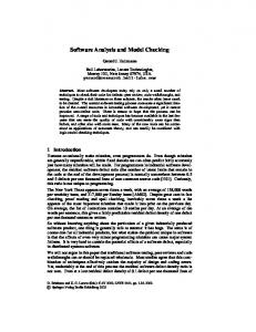
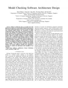
execution of state transitions. Fig 1 illustrates XTG modeling using a combination of location invariants and guarded edges of time-interval semantics. Upon execution a transition may update clocks and data. Edges are either urgent or non-urgent. Urgent edges (marked with a black blob at the starting point of the edges) should be taken immediately after enabling the previous state. Non-urgent edges may be taken as soon as they are enabled.
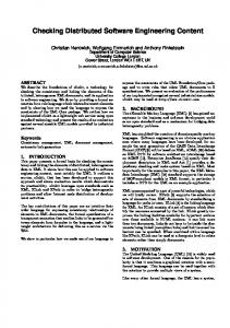
Figure 1 A simple XTG model Our property specification language is a temporal logic based on TCTL (Timed CTL) [10]. We replaced the TCTL reset quantifier by assignments to specification clocks and variables. In our TCTL variant z:= 0.AF (p Λ z ≤ 10) expresses that p will always become true sometime within 10 time-units. The core syntax defines two temporal operations AU and EU. The formula (φ1 AU φ2) is satisfied in a state if for all computation paths starting from that state there is a state along it, which satisfies φ2 and until that time φ1 is satisfied. The formula (φ1 EU φ2) is satisfied if there is at least one such computation path. One of the derived operations is: AGφ (on all paths every state satisfies φ). We used the LPMC model checker (Linear Prototype Model Checker) [9, 14] developed at Delft University of Technology to deal with a XTG model associated with TCTL property specifications. For a thorough description of the LPMC tool see [13]. D. Implementation: In this project two engineers were working parallel on the system to be developed. Java technology was chosen for implementation of the software and LEGO Mindstorms was chosen for the mechanical and electrical part of the system. The integrated development environment (IDE) used was Eclipse to which extra functionality can be added by developing plug-ins. The target environment for the software is the LEGO Mindstorms RCX, a repackaged Hitachi H8/32927 micro controller. A Java virtual machine, called leJOS, is loaded on the RCX. It occupies about 16 KB, leaving 16 KB for embedded software on the RCX. An Eclipse plug-in for leJOS is available, which enables a developer to download firmware (containing the leJOS virtual machine) and Java byte code to the RCX from the IDE E. Integration: The integration process combines the disciplines of system and software development as discussed above. Fig 2 depicts the ideal integration of these disciplines
as emphasizing the processes, the artifacts and the links between the processes. On the left hand side we partly see the traditional waterfall model. First we specify the requirements of the system (a) then these are used in the design process (b) to create an architecture and detailed design of the system, finally the system is implemented (c). On the right hand side the role of model checking is shown. On every development level a set of properties can be specified and a model can be extracted with corresponding properties (d). These are both input for the verification process (e), which results in a verification report. This report is used as feedback (f) to the requirements set, architecture and implementation.
Figure 2 Integration of model checking in embedded software development In the ideal situation, the properties of the design level should be strongly related to the properties on the requirements level (g). Otherwise we cannot guarantee that the properties on the design level correctly satisfy the requirements, because these properties are then only extracted from the design (d2). On the implementation level a similar issue has to be dealt with. In ELM, we applied discussed technologies and conducted verification on the design level. During the experiment, several problems emerged that will be discussed in the next section with reference to Fig. 2. III. RESULTS Our first aim was to apply model checking techniques in the embedded software development process according to our ideal model (Fig 2). In our practical experiment, the results
were not completely satisfactory: on the one hand, for rising software complexity, it often produced unmanageable structures; on the other hand, for deriving properties which are strongly related to the requirements (g) creativity, experience and significant effort is needed, i.e. the same harship as in the design process (b). Because of such difficulties, in this paper, we take into account properties that are weakly based on the requirements level. The dotted arrow in Fig 2 shows this process. We focused on the integration of process (b) and the extraction of a correct model from the design (d2). For the verification process (e2), we needed the desired properties derived from the requirements (dotted arrow). In order to prove the correctness of the design, LPMC was successfully applied to check whether the extracted model satisfied the properties we defined. This verification was based on design ideas that were relatively easy to implement. Additionally, verification succeeded in pointing out some errors, when some design decisions resulted in undesired behavior of the implementation. For instance, the light sensor’s values were not interpreted correctly, resulting in failure to detect the source image while scanning. The results of system verification provided important information: we put a description of a model (the possible behavior) and a description of the requirements specification (the desirable behavior) into the verification tool (LPMC). If an error was recognized, LPMC provided a counter-example showing under which circumstances the error could be generated. Thus, the counter-example provided evidence that the design was faulty and needed to be revised. This feedback helped us to find and repair these errors, so that the design could be improved. Finally we proved various properties related to safety such as absence of deadlock and correct behavior of the system. The most important scenario for a copy machine is that all values sent by the scanner are received and printed by the plotter. This means that for a source image of the scanner (SCM), and a target image of the plotter (PCM), which are represented by position and color values, the following properties should hold: AG ( SCM.position == xp Æ PCM.position == xp ) AG ( SCM.color == black Æ PCM.color == black) As well known, the algebra expression P = A Æ B is equivalent to the expression P = not A or B [15]. Thus properties are represented by: AG (SCM.position != xp) or ( PCM.position == xp ) AG ( SCM.color != black) or ( PCM.color == black) These properties could be verified. It showed that the system
is valid for given properties. For us, this result is a first confirmation of the practical usefulness of the integration of model checking into the embedded software engineering process. Of course it must be enhanced. To improve the quality and development productivity of software in the embedded domain, we should consider not only the left hand side of Fig 2 with its extractions (d1, d2 and d3) to the right hand side, but also the derivation of properties which are strongly based on the requirements level (g1 and g2). In the next section, we will discuss problems we encountered during our case study with respect to future work in detail. IV. DISCUSSION AND FUTURE WORK After reading the results in the previous sections the first question that arises is: Do such formal verification techniques contribute to the embedded software development process? Formal verification techniques can certainly contribute: the results section has shown that design errors can be found and corrected by verification. For validation of the design we selected properties, which are weakly based on the requirements. However, in order to improve the efficiency of the embedded software development process, this is not good enough to validate. More work needs to be done to deal with this problem, i.e. more experiments to derive properties, which are strongly linked to the requirements level. With respect to the design process, several integration possibilities on the area of requirements management, architecture design, detailed design, and implementation were tested. Eventually these trials resulted in an architecture. Now the second question is: How to select verifiable properties and generate a model from informal or semi-formal diagrammatic notations, paradigms, and tools? For instance, in our experiment the necessity of an additional transformation was inevitable. It seems we should have done extra work for translating informal or semi-formal output of the design process into formal input for the verification process. We used an approach that involved several manual and theoretical contemplations for process (d2). In this step there are some possibilities to make mistakes when using manual approaches, resulting in an incorrect model. Thus, techniques or tools for this particular drawback should be considered by combining different viewpoints upon a valid system without errors made by human mistakes. Thus, this second question can be concretized like: How can CASE tools or techniques sensibly support the translation of UML descriptions into the automata models for LPMC? Answers for above questions are to be found in collaboration with an industrial partner that is running a case study in a project that redesigns a train monitoring system Another formulation of our problem is that we want to find
solutions to reduce the complexity of models of large-scale systems. Advances in formal verification techniques and tools are needed to cope with the increasing software complexity. Else correctness guarantees will remain forever unfeasible. It can be said that the behavior of embedded systems may result in an infinite number of states due to unbounded parameters such as time values. Therefore, other approaches should be applied, such as minimization of complexity and abstraction interpretation [12]. The latter suggests some additional refinements of the model checking algorithms [14] used in this experiment. Our research related to this problem is currently ongoing as part of the PARTES project [11]. We plan to extend LPMC with the facility for minimizing the data space. At the same time, we will optimize our implementation with efficient data structures and approximation heuristics algorithms [12] to reduce state spaces. REFERENCES [1] MOOSE homepages. http://www.mooseproject.org, 2003. [2] S. Chandra, P. Godefroid, C. Palm. Software Model Checking in Practice: An Industrial Case Study. In Proceedings of the 24th International Conference on Software Engineering (ICSE 2002), page 431–441. ACM Press, 2002. [3] R. Kazman, M. Klein, P. Clements. ATAM: Method for Architecture Evaluation, CMU, Software Engineering Institute, August 2000. [4] IEEE Guide for Developing System Requirements Specifications. IEEE Std. 1233-1998. [5] IEEE Recommended Practice for Software Requirements Specifications. IEEE Std. 830-1998. [6] C. Hofmeister, R. Nord, D. Soni. Applied Software Architecture. Addison-Wesley, 1999. [7] P. Clements, F. Bachmann, L. Bass, et al. Documenting Software Architectures. Addison-Wesley, 2002. [8] R.Alur and D.Dill. The theory of timed automata. Theoretical Computer Science 126:(2) 183-235, 1994 [9] M. Ammerlaan, R. L. Spelberg and W.J. Toetenel. XTG-an engineering approach to modeling and analysis of realtime systems. In Proceedings of the 10th Euromicro Workshop on Realtime systems. IEEE 1998. [10] T.A. Henzinger. Nicollin J. Sifakis and S. Youvine. Symbolic model checking for real time systems. Information and Computation, 1994. [11] R.F.Lutje Spelberg and W.J. Toetenel. NOW open competitie project Parametric Analysis of Real Time Embedded System. Project technical Report 8 pages, 2002 [12] J. Bertrand Dynamic Partitioning in Linear Relation Analysis application To The Verification of Reactive System. Formal methods in System design, BRICS Research Report. http://www.brics.dk/RS/00/38 [13] LPMC hompage. http://tvs.twi.tudelft.nl [14] R.F.Lutje Spelberg and W.J.Toetenel. Parametric real-Time Model Checking using Splitting Trees. Nordic Journal of Computing, 2001 [15] D. van Dalen. Logic and Structure. Page 7 -10. Springer-Verlag, 1994