Intelligent Dynamic Traffic Light Sequence Using RFID Khalid Al-Khateeb, Jaiz A. Y. Johari Electrical and Computer Engineering Department, Faculty of Engineering International Islamic University Malaysia, Kuala Lumpur, Malaysia
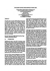
[email protected] [email protected] occurs, there is no proper way of dealing with such development. A more elaborate approach has been introduced to overcome these problems. It employs real-time traffic flow monitoring with image tracking systems [3], [4]. Although this method can give a quantitative description of traffic flow [5], it involves several limitations. The processing in real time on a large scale, may present prohibitive requirements. Some common problems involved in image processing system include False Acceptance Rate (FAR) and False Rejection Rate (FRR). Normally, in case of jampacked traffic, the computer vision results in erroneous detection [3]. The multilane traffic sequence flow is presented in figure 1.
Abstract The proposed RFID traffic control avoids problems that usually arise with standard traffic control systems, especially those related to image processing and beam interruption techniques. This RFID technique deals with a multi-vehicle, multilane, multi road junction area. It provides an efficient time management scheme, in which a dynamic time schedule is worked out in real time for the passage of each traffic column. The real time operation of the system emulates the judgment of a traffic policeman on duty. The number of vehicles in each column and the routing are proprieties, upon which the calculations and the judgments are based. Keyword: RFID, traffic sequence, dynamic time schedule I. INTRODUCTION The operation of standard traffic lights which are currently deployed in many junctions, are based on predetermined timing schemes, which are fixed during the installation, and remain until further resetting. The timing is no more than a default setup to control what may be considered as normal traffic. Although every road junction by necessity requires different traffic light timing setup, many existing systems operate with an over simplified sequence. This has instigated various ideas and scenarios to solve the traffic problem. To design an intelligent and efficient traffic control system, a number of parameters that represent the status of the road conditions must be identified and taken into consideration. Most of the present intelligent traffic lights are sensor based with a certain algorithm that controls the switching operation of the system [1], [2] and [10]. This approach considers the traffic to be moving smoothly, and hence does not require any management or monitoring of traffic conditions. When some unpredictable situation developed, or when congestion
Figure 1. Multilane traffic sequence flow
The sensor based traffic light control on the other hand may require sensors that operate with a line of sight detection, which may present difficulty in detecting vehicles that pass through blind spots detection range. The RFID technology offers an
1367
advanced object tagged recognition which support the intelliegent dynamic traffic sequence algorithm.
multiple junction control. It is based on an automatic intelligent selection of traffic sequence in a multilane traffic flow.
II. EXPERIMENTAL SETUP A model of the system has been set up to simulate the actual design of a novel RFID based traffic control using Cisco appliance and AeroScout RFID active tag. The layout is shown schematically in figure 2.
Next State 0 1 R R G Y Y R G G Y
Next State A B C D
0 A B C D
1 B C D A
Figure 3. Traffic light state diagram
Figure 3 shows an example of how the algorithm works. Assuming A, B, C and D are traffic column in which A from south can go forward, east or west, with timing slot that is dynamically determine according to the number of vehicle for each route. The same sequence is then shifted to B, C then D.
Figure 2. Model of the RFID based traffic control system
The intelligent traffic control system consists of four main parts: the AeroScout RFID tags, the Cisco access point, the Cisco location server and Wide Area Network (WAN). The first simulates the moving vehicles, the second detects the RFID tags, the third acts as an RFID software, and fourth simulate the ubiquitous environment. The location server acts as the microcontroller of the traffic signal. It will collect the location and tagging time the data from reader. This information is sent to the management system via internet. The management system using intelligent algorithm will then send suitable instructions to control the traffic.
Figure 4. RFID Reader reading range
The decision process for the intelligent traffic control depends on the real time information as provided by the RFID system. The data is also recorded and saved in the centralized management database. A number of readers are deployed to detect and count the vehicle at each junction. The reader captures the time-in for each vehicle passing within its range. Figure 4 illustrate the practical arrangement and the
III. DYNAMIC TRAFFIC SEQUENCE ALGORITHM An algorithm for the control of the traffic sequence that can change dynamically the priority and easy to implement is written to facilitate the efficient traffic control at certain junction. This also can be extended to
1368
location of the reader around the junction. The captured information such as location and time for each vehicle are saved as a tag reference table as shown in equation 3.1. ID: : < Time (tn) >
The decision takes into account real-time data at surrounding junction as well as statistically compiled data for a specific time of the day and day of the week, and may even consider weather the data coincide specific event.
(3.1) TABLE 2: CAPTURED TIME-IN
Vehicle
TABLE 1: WAITING TIME AT EACH STATE
State
Waiting time at each state
A
AY + BG + BY + CG + CY + DG + DY
B
BY + CG + CY + DG + DY + AG + AY
C
CY + DG + DY + AG + AY + BG + BY
D
DY + AG + AY + BG + BY + CG + CY
Theoretically the waiting time at each junction is same as defined in table 1. This algorithm can changed the sequence dynamically depending on the real time situation at the specific junction with respect to situations that currently exist in other junctions of the surrounding area. If the accepted waiting time at each junction is 90 second, the period for Green and Yellow states must be 30 second at each junction. In reality the state of traffic condition and congested changed with time. Hence, the timing for a Yellow state can be fixed to be 3 seconds which is long enough for a driver to stop. The waiting time for example can be computed for a state A as shown below:
Await = BG + CG + DG + AY + BY + CY + DY Await = BG + CG + DG + 4(3s )
Vehicle 1 Vehicle 2 Vehicle 3 Vehicle 4 … Vehicle n
Sensor Ax
Sensor Ay
Sensor Az
Tx1 tx2 tx3 tx4 … txn
Ty1 Ty2 Ty3 Ty4 … tyn
Tz1 Tz2 Tz3 Tz4 … tzn
Figure 5. Reader reading the passing through tag
TABLE 3: COLLECTED VEHICLES SPEED DATABASES
AxAy v11 v12 v13 … v1P
Await = BG + CG + DG + 12s
Database of the Speed of Moving Vehicles AyAz BxBy ByBz CxCy CyCz DxDy DyDz V21 v11 v21 v11 v21 v11 v21 V22 v12 v22 v12 v22 v12 v22 V23 v13 v23 v13 v23 v13 v23 … … … … … … … v2P v1P v2P v1P v2P v1P v2P
v – Speed of the vehicles between two readers l – location of the RFID reader t – Time tagged the RFID tag at the particular reader n – Number of reader P – Total number of vehicles traveling between two readers
Await ≠ B wait ≠ C wait ≠ D wait
(3.2) The Green state timing of AG, BG, CG and DG at each junction can be different from each other because it depends on the conditions and the queue length. If no vehicles are detected at a particular state, then the sequence automatically proceed to the next state. On the other hand if number of vehicle in a congested state in along queue, the system will check the condition of other junction and determine a compromising time for maximum efficiency in relieving the congestion. This will allow a reasonable balance for the overall waiting time.
The raw data from the readers is accumulated in the centralized database and arranged in a database table as shown in tables 2 and 3. It is base on the vehicles movement shown in figure 5. The database also records the average speed of all vehicles traveling between two readers within the area of the controlled zone. Then accumulated speed average in the area before reaching the traffic light is for all area before reaching the traffic light is calculated as below.
1369
v1 = v1
l 2 − l1 t 2 − t1
collect
routing of the traffic utilizing the intelligent algorithm for the traffic flow system. The average acceleration and average speed of a vehicle which is moving from standstill when after the traffic light turns green can also be computed.
(3.3)
= vi
i=P i =1
(3.4)
collect
i=P
∑v i =1
(v1 ) avg =
v avg
a avg = v avg
i collect
(3.5)
P1
(v1 ) avg + (v 2 ) avg
=
collect
2
collect
v avg =
In the case where other than RFID are used in the system such as image processing and traffic sensor, the algorithm proposed in this work will improve their performance by reducing the size of computational data since the size RFID tag data is in a few bytes and providing proper basis for the estimation assume in normal fuzzy logic analysis procedure discussed in. [2], [6], and [7]. The algorithm is required to process all the data captured from the moving vehicles which have been tagged with RFID tag. This algorithm examines whole traffic environment and decide a procedure to control the switching process of the traffic lights, as shown in figure 3. If this system senses an odd situation such as an accident that causes imbalance traffic flow, it would still be capable to control the traffic by allowing the appropriate junction manipulation. The decision makes use of the accumulated data saved in centralized traffic management databases. The system can learned from the accumulated decisions and can be produce an overall scenario of the traffic flow by identifying a variety of situation e.g. • Identify the junction with a longest queue • Identify the busiest route • Identify the routine traffic pattern at particular time and day • Determine the most efficient sequence The traffic controller algorithm is defined as follow:
(3.6)
(3.7)
2 j =3
v avg =
i avg
i =1
l j − l j −1
∑t j =1
j
− t j −1
(3.8)
P2
TABLE 4: TABLE FOR MONITORING CONGESTED ROUTING
Total Number of Moving Vehicles From A(x,yz) to B(z,y,x) C(z,y,x) D(z,y,x) ∑vehicle
∑vehicle
∑vehicle
Total Number of Moving Vehicles From B(x,yz) to A(z,y,x) B(z,y,x) C(z,y,x) ∑vehicle
∑vehicle
∑vehicle
Total Number of Moving Vehicles From C(x,yz) to D(z,y,x) A(z,y,x) B(z,y,x) ∑vehicle
∑vehicle
If A1,A2,A3: G then B1:G until A1,A2,A3:Y
∑vehicle
Total Number of Moving Vehicles From D(x,yz) to A(z,y,x) B(z,y,x) C(z,y,x) ∑vehicle
∑vehicle
(3.9)
aavg – average acceleration
i =2
∑ (v )
dv dt
If only A3 not detected at B(z,y,x), then A3:Y then compare queue at C(x,y,z) and B(x,y,z) { if C(x,y,z) > B(x,y,z) then C1,C2:G until A1and A2:Y else C1,B1:G until A1 and A2:Y } then B1,B2,B3 start G
∑vehicle
The average speed information and the estimated are important parameter in determining the proper
1370
The tagged object may be a sticker on a road tax badge, a license, a number plate or a special permit. Each tag carries detailed information about the vehicle such as type, weight, length, similar to the centralized traffic management database information. It is found that the RFID tag developed by Security Lab Inc. as shown in table 5 may result in an overall improvement in the performance of the system over the use of the AeroScout tag, because it is specifically designed for fast moving objects. It can operate up to 180 km/h.
If only A2 not detected at C(z,y,x), then A2:Y { then D1,C1:G until A1and A2:Y } then B1,B2,B3 start G If A1 not detected at D(z,y,x) AND If A2 not detected at C(z,y,x), then A1,A2:Y { then D1,C3:G until A3:Y } then B1,B2,B3 start G
TABLE 5: SPECIFICATION OF RFID TAG FOR THE PROPOSED RFID BASED TRAFFIC MANAGEMENT SYSTEM
If A2 not detected at C(z,y,x) AND If A3 not detected at B(z,y,x) then A2,A3:Y then compare queue at C(x,y,z),B(x,y,z) and D(x,y,z) { if B(x,y,z) > C(x,y,z) and D(x,y,z) then B3,B1:G until A1:Y if C(x,y,z) > D(x,y,z) and B(x,y,z) then C1,C2:G until A1:Y if D(x,y,z) > B(x,y,z) and C(x,y,z) then D1,D2,D3:G until A1:Y } then B1,B2,B3 start G If A1,A2,A3 not detected at A(x,y,z) then B1,B2,B3 start G
Features
Security Lab Inc. Specification
Transponder type
Active
Reading range
Up to 80 meters
Maximum object speed with guaranteed tag reading
Up to 180 km/h
Frequency
434.5 MHz, 433.3 MHz
Life time battery
1 year
Radio emitted power
Less than +10 dBm
The system can randomize the reply time so that it can query multiple tags simultaneously and minimize the contention between their responses. The RFID reader is located in a way, which makes it possible to collect the information from the vehicles that pass through its reading range. The information is then sent to the centralized database of the management system. The centralized system processes the collected information and generates feedback signals that manage the intelligent traffic light sequence, as illustrated in figure 6. The statistical data in the centralized database can be shared with local databases through a secure structured network [8], [11] and [12].
The same algorithm applied to states B, C and D in order to avoid long queuing times at congested lane, to provide an efficient flow rate to the most congested route. IV. MODEL ENHANCEMENT AND PLANNING This algorithm can be scaled up readily to deal with much more complicated traffic problems. Large scale deployment of the ubiquitous RFID network will provide an integrated comprehensive solution, which considers the traffic flow as the blood stream in a living being. The basic requirement for ubiquitous RFID network deployment is that every vehicle must carry a tag. This requirement may involve decisions by higher authorities and implementation of policies by executive authorities [8] and [14]. The RFID system can be enabled by the ubiquitous sensors, which are made part of input devices in the traffic management application. Extending the interface capabilities of the sensor is not a complicated process [9]. The tag is usually placed on the object to be identified or embedded in it.
Figure 6. Schematic design of the Ubiquitous RFID Network for Traffic Light Management
1371
V.
usage in Malaysia will rapidly grow. This advancement may to the invention of more RFID systems and applications, as the cost of the technology gets lower with the expected mass production.
CONCLUSIONS
This technique may revolutionize the management of traffic systems in Malaysia, if it is implemented on a large scale commensurate with a comprehensive plan for an automated transport system. The main feature of this operation is the ability to communicate with any head-quarters local or central at any location securely via the internet. This system can help in reducing the loss of valuable time as well as the number of accidents and may solve many common problems that exist within any traffic system The dynamic time management scheme operates in real time and emulates the judgment made by a traffic policeman on duty. This system aims at saving a large amount of man-hours caused by traffic problems and accidents, where prevention can save lives and property. It is able to manage priority emergency tag vehicles. It offers a valuable detailed database records and preference to planner and investigators. In order to ensure the smoothness of this implementation, a lot of effort is require to integrate the management of the databases among the local authorities. Sharing a secured database and protocol must be designed to integrate with the existing system. The issues of the integration require collaboration with the authorities that are concerned with managing the databases and need to be discussed further at higher levels. The legal issues and privacy laws relating to the monitoring of drivers all the time will be the future challenge as this matter is predicted to be a debatable public concern. Such study would need to address, and discuss in details subjects regarding the issues of the civil rights and personal freedom, and whether it is morally acceptable to implement RFID in an open manner or be it restricted to specific legally defined applications. One of the issues that need to be highlighted to the MCMC is to allocate the license control of bandwidth ranging from 430 MHz to 440 MHz for RFID application [13]. This frequency range can enhance the reading range for RFID tag reading capability. By improving this capability, the development of RFID
REFERENCES [1] [2] [3] [4]
[5] [6]
[7]
[8]
[9] [10]
[11] [12] [13]
1372
Han T. and Lin C., “Design of an Intelligent Traffic Light Controller (ITLC) with VHDL”, Proceeding of IEEE TENCON’02, pp. 1749-1752, 2002. Albagul A., Hrairi M., Wahyudi, Hidayathullah M.F., “Design and Development of Sensor Based Traffic Light System”, American Journal of Applied Sciences 3 (3): 1745-1749, 2006. Tseng S. T. and Song K. T. “Real-Time Image Tracking for Traffic Monitoring”, IEEE, 5th International Conference on Intelligent Transportation Systems, Singapore, 2002. Rabie T., Shalaby A., Adbulhai B. and Rabbany A.E., “Mobile Vision-Based Vehicle Tracking and Traffic Control” IEEE, 5th International Conference on Intelligent Transportation Systems, Singapore, 2002. Ferier N. J., Rowe S. M., Blake A. “Real-time Traffic Monitoring”, Proceedings of the Second IEEE Workshop on Application of Computer Vision, pp 194-199, 1994. Taskin H., and Gumustas R., “Simulation of Traffic-Flow System and Control Using Fuzzy Logic” Proceedings of the 12th IEEE International Symposium on Intelligent Control, Turkey, 1997. You-Sik H., Hyunsoo J., and Chong-Kug P., "New Electrosensitive Traffic Light Using Fuzzy Neural Network", IEEE Transaction on Fuzzy Systems Vol. 7 No.6, Dec 1999. pp 759-767. Johari J and Khateeb K, “Ubiquitous RFID Network for Highway Monitoring and Management” IEEE, International Conference on Computer & Communication Engineering (ICCCE), Kuala Lumpur, 2006. Want R. “Enabling Ubiquitous Sensing with RFID”, Computer, April 2004. Hasan Ibrahim A., Ismail M., Keong T. S., Kader Mastan Z. B., “Development of Software Planning Tools for an Intelligent Traffic Light Wireless Communication Link Using 5.8GHz WLAN” IEEE, Asia Pacific Conference on Applied Electromagnetics Proceedings, Johor, 2005. Bamford R., Ahad R. and Pruscino A., “A Scalable and High Available Networked Database Architecture” Proceeding of the 25th VLDM Conference, Edinburgh, Scotland 1999. Pradip D., Kalyan B., and Sajal K. D., “An Ubiquitous Architectural Framework and Protocol for Object Tracking using RFID Tags”, IEEE MobiQuitous, 2004. “Requirements for Radio Frequency Identification Device (RFID) Operating in the Frequency Band from 919MHz to 923 MHz” MCMC SRSP-530 RFID, 31 October 2005