JOURNAL OF NETWORKS, VOL. 7, NO. 2, FEBRUARY 2012
365
Intelligent Storage and Retrieval Systems Based on RFID and Vision in Automated Warehouse Yinghua Xue School of Computer and Information Engineering, Shandong University of Finance, Jinan, China Email:
[email protected]
Hongpeng Liu Shandong Meteorological Science & Technology Service Center, Shandong Meteorological Bureau, Jinan, China Email:
[email protected]
Abstract—The automated warehouse is widely used in different kinds of corporations aiming to improve the storage and retrieval efficiency. In this paper, the robot system with RFID and vision was applied into the design of warehouses. Firstly, the RFID system is used to localize the target roughly and obtain the attributes of the target. Then the onboard vision system is used to recognize and locate the target precisely. Finally, the robot control scheme is designed based on the results of image processing, and the teaching mode and remote mode are used flexibly to assist robot to grasp the target. The combination of these two modes can not only reduce the complexity of robot control, but also can make full use of the results of image processing. Experiments demonstrate the feasibility of the proposed system. Index Terms—intelligent storage and retrieval systems, robot control, RFID, robot vision, automated warehouse
use radio transmissions to send energy to a tag which, in return, emits a unique identification code back to a reader linked to an information management system. If the RFID tags with unique codes are embedded in objects, the identification of the objects can be greatly simplified. Furthermore, RFID has a lot of advantages, such as contactless communications, long lived, high data rate, non line-of-sight readability, and low cost [3,4,5]. For the above reasons, RFID technology has been often employed to recognize objects for navigation, manipulation, etc. Based on the above analyses, a kind of new RFID based AS/RSs is proposed in this paper in order to realize target recognition, automatic localization and AS/RS, which can not only improve the precision and speed of the automated warehouse, but also be suitable to the management of modern corporation.
I. INTRODUCTION
II. STRUCTURE OF AUTOMATED WAREHOUSE
In order to improve the efficiency of storage and transportation of goods, the warehouse is widely used in different kinds of fields. The current warehouses which are often operated manually usually include palletizing robots, carton flow order picking systems, automated guided vehicles, rotary storage cabinets, and automated storage and retrieval systems (AS/RSs) [1,2]. The main shortcoming of the current warehouse is that the efficiency of its storage and retrieval systems is very low, which is also a bottleneck to restrict the development of automated warehouse. Therefore, how to improve the efficiency of AS/RSs, and realize intelligent control without manual intervention becomes a very important issue. In recent years, because of its ubiquity, radio frequency identification (RFID) technology has becoming the hotspot in the field of object location. RFID systems
The automated warehouse is composed of four rows of automated shelves including 120 cargo spaces divided into two tunnels, an automated stacker, two storage and retrieval platforms, and a SK6 manipulator with sixfreedom, etc. SK6 produced by Yaskawa is used in the warehouse. The controller of SK6 is YASNAC MRC Ⅱ , which adopts interactive programming language INFORMⅡ . There are two programming ways: teaching and remote control. In this paper, we combine the two ways together to simplify the system design. The RFID system mainly includes three parts: reader, antenna, and RFID tag. Because of the uniqueness of the RFID tag, the reader can locate and track the target once it is attached on an RFID tag. Passive tags are used to attach on the target object because they are much cheaper, long lived, lightweight and have a smaller foot print. The reader can communicated with host computer through RS232. The CCD camera is mounted on the end of the arm, which can distinguish the target using color and shape of the object. The control system of the automated warehouse include management/monitor computer, master PLC and
Manuscript received January 12, 2011; revised March 9, 2011; accepted May 6, 2011. Yinghua Xue, is a lecturer of Shandong University of Finance. Her research interests include automated warehouse, multi-sensor information fusion, object localization and operation. E-mail:
[email protected]
© 2012 ACADEMY PUBLISHER doi:10.4304/jnw.7.2.365-369
366
JOURNAL OF NETWORKS, VOL. 7, NO. 2, FEBRUARY 2012
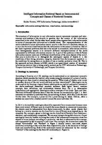
lower PLC, which are connected by Modibus and wireless networks and can build up a complete multilevel computer monitoring system, as shown in Figure 1. The whole automated warehouse system integrated cargo storage, retrieval, distribution and transportation together, realizes intelligent operations in the whole system, and is an intelligent warehouse without any manual operation.
⎡N ⎤ ( X T , YT ) = ⎢∑ ( X i , Yi )⎥ / N ⎦ ⎣ i =1
(1)
where N is the number of conference tags. Robot moves near the weighing platform RFID
Robot
technology
Calculate the rough position of target Robot Controller
CCD Camera
Host Computer
RFID
Move to the vicinity of the target
Recognize the target using the onboard vision
Main PLC Modibus
Vision of robot
Adjust the pose of the robot Lower PLC
……
Lower PLC Grasp the target
Terminal Device
……
Terminal Device
Failure
Success Deliver to the storage and retrieval platform
Figure 1. The control system of automated warehouse.
III. INTELLIGENT STORAGE AND RETRIEVAL SYSTEMS
Figure 2. Flowchart of intelligent storage and retrieval.
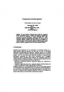
RFID and vision based intelligent storage and retrieval systems are shown in Figure 2. The system mainly includes two parts: RFID and vision systems. RFID technology is used to localize the target roughly, and onboard vision is used to localize the target precisely. A. RFID Localization System Inspired by LANDMARC positioning system [6], the conference tags are introduced in the paper. The conference tags divided into 5 rows 6 columns are distributed on the bottom of a tray, shown in Figure 3. The real position of each conference tag is recorded in it. Furthermore, each of the considered target objects of the database is also attached to an RFID tag, which is called as target tag. When the reader detects the conference tag and the target tags, the robot can know the name and count of real targets in its detecting field, which can reduce the number of matching items in the database, and the rough position of the target can also be calculated. In Figure 3, the green box indicates the conference tag, and the red circle represents the detection range of the RFID antenna. The other colored shapes mean different targets. From Figure 3, we can conclude that there are 6 conference tags and 3 targets in the detection range of RFID, so the rough position of the target can be calculated as:
© 2012 ACADEMY PUBLISHER
Figure 3. Distribution of reference tags.
B. Robot Vision System When the rough position of target is determined, the manipulator recognizes the target using the onboard camera. In this paper, the color and shape information are used to recognize the target [7,8]. (1) Target Recognition The video provided by camera is in RGB space. In order to reduce the influence of light, we transform the RGB space to YCbCr space which can separate the illumination from hue. Gaussian model is used to color
JOURNAL OF NETWORKS, VOL. 7, NO. 2, FEBRUARY 2012
367
detection because the parameters are easily to calculate and the detection rate is high. For the image transformed to YCbCr space, the similarity degree to the target is calculated as: (2) p(CbCr ) = exp[−0.5( x − m)T C −1 ( x − m)] where x = (CbCr ) , m = E ( x ) = (Cb, Cr ) , Cb and T
Cr are the means of Cb and Cr , C is the variance matrix and C = E[( x − m)( x − m) ] . Next, the similarity image is transformed to a binary image, and the white regions are the interesting areas where the target may exist. The interesting areas still include some other regions whose color is similar to the target, so the shape information is used to extract the target accurately. Moment function is global invariant, less sensitive to noise, and could be used to identify the target successfully whether the target is closed or not. Therefore, moment invariants have been widely used in shape recognition and identification. In this paper, Hu invariant moments [9,10] is used to deal with the interesting area image after image segmentation, and the nearest area is selected as the target area. (2) Target Tracing The target recognition is not very stable due to the image processing is influenced by sunlight. A kind of target tracing algorithm based on Kalman Filter is designed in the paper in order to forecast and trace the target. Kalman Filter [11,12] is used to predict the position of the target, and the center coordinate values, the area of the target, the ratio of length and width, and one dimension HSV histogram are used as the features of the target. The main process is shown as follows: T
Figure 4. The transmission process of a file
(2) Command transmission Figure 5 shows the command (DELETE WORK-A) transmission process from the host computer to YASNAC MRCⅡ.
X v (k | k − 1) = Fv (k ) X (k − 1 | k − 1)
Pvv (k | k − 1) = Fv (k ) Pvv (k − 1 | k − 1) FvT (k ) + Q
X v (k | k ) = X v (k | k − 1) + K (k )(Z (k ) − H (k ) X v (k | k − 1) )
Pvv (k | k ) = Pvv (k | k − 1) − K (k ) S ( k ) K T ( k ) S (k ) = H (k ) Pvv (k | k − 1) H T (k ) + R K (k ) = Pvv (k | k − 1) H T (k ) S −1 (k )
(3) The experiments demonstrate that the algorithm can trace the target stably, and can solve the occlusion problem to some extent. C. Robot Control System YASNAC MRCⅡ is used as the controller of SK6, which is composed of Playback Box, Main Power Switch, Door Lock, and Programming Pendant [13,14]. Teaching Programming is an important mode in robot control, and it is simple and can be used to plan path. YASNAC MRC Ⅱ support host computer control function. According to different commands sent by the host computer, it can be divided into two classes: file data transmission and command transmission. (1) File data transmission function File data transmission function can realize data exchange between the user’s memory data stored in YASNAC MRCⅡ and the data stored in host computer. The transmission process is shown in Figure 4.
© 2012 ACADEMY PUBLISHER
Figure 5. The transmission process of a command
Ⅳ. EXPERIMENTS AND ANALYSES A. Intelligent Storage and Retrieval Experiment Taken automated retrieval operation as an example. The target is placed on the rotary platform, the manipulator first localize the target using RFID, then recognize and trace the object using onboard vision, finally grasp the target and place on the weighing platform. The procedure is shown below: (1) The manipulator move to the stat point which is near the rotary platform.
368
© 2012 ACADEMY PUBLISHER
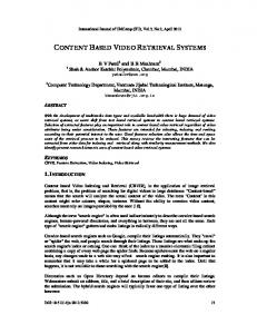
B. Performance Evaluation The system is valuated mainly form the following two aspects: positioning accuracy and efficiency of storage and retrieval system. (1) Positioning accuracy Figure 6 shows the positioning error of one typical target in different conditions. We can see that in conventional pattern, the robot only used vision to localize the target. When the distance between robot and target exceeds 1.2 meters, it is difficult to distinguish the target. Even if the distance is below 1.2 meters, the positioning error is higher and fluctuates largely. While in our method, the robot can not only obtain the rough position of the target, but also the information stored in target tag in advance, such as color and size, which are both helpful to localize the target precisely. So the positioning precision based on multi-pattern (RFID and vision) is higher and the positioning system is more stable, too. Positioning error
error(cm)
15
10
5
0 40
50
60
70
80
90
100 110 120 130 140 150
Distance between robot and target(cm) conventional pattern
multi-pattern
Figure 6. Positioning error
(2) Efficiency of storage and retrieval system Figure 7 shows the efficiency in different methods. We can conclude that our method adopts multi-mode information provided by RFID and vision, and can improve the efficiency about 50%. Efficiency comparision 1.5 time(s)
The coordinate values are: 829.461 , 29.261 , 517.968,175.50,2.24,-176.78. The first three data (mm) are the coordinate values of X, Y, and Z axis, respectively. The latter three data are the degrees of TX, TY, and TZ angles. (2) Adjust the end of the actuator to make it perpendicular to the rotary platform. The coordinate values are: 1139.372 , 35.096 , 567.047,39.48,87.38,41.30. This position should meet the requirements of object recognition using RFID and vision. (3) Delay 3 seconds. First the RFID is used to localize the target roughly, and then the target is recognized precisely using onboard vision. Finally, the coordinate values of the center point is calculated and written to the position variable P000 in YASNAC MRCⅡ. The coordinate values are: 1175.012 , 50.227 , 371.339,68.18,87.63,69.44. (4) The manipulator is adjusted slightly to be close to the target. The coordinate values are: 1185.014 , 70.222 , 371.341,68.18,87.63,69.42. (5) The manipulator grasps the object, and then delay 1 second. The coordinate values are: 1185.014 , 70.221 , 361.341,68.18,87.63,69.42. (6) The manipulator moves to the top of the rotary platform. The coordinate values are: 1109.141 , 46.776 , 687.747,78.18,84.76,81.98. (7) The manipulator moves to the top of the weighing platform. The coordinate values are: 317.513 , 1063.751 , 687.747,78.18,84.76,152.98. (8) The manipulator places the object on the weighing platform. The coordinate values are: 317.652 , 1084.249 , 424.544,79.19,84.69,151.69. (9) The manipulator moves to the top of the weighing platform. The coordinate values are: 286.537 , 990.862 , 721.899,44.33,82.64,119.31. (10) The manipulator moves near the staring point, and the task is ended. The coordinate values are: 737.606 , 26.728 , 496.366,175.50,2.24,-176.78. From the experiments, we can conclude that: (1) The manipulator can trace the planned path accurately. (2) The host can read the data file and generate the command sequence correctly, and can save the data to the variable to control the robot grasping the target. (3) The teaching and remote modes are used flexibly in the paper, which can not only simplify the programming, but also can improve the flexibility of the automated storage and retrieval system.
JOURNAL OF NETWORKS, VOL. 7, NO. 2, FEBRUARY 2012
1 0.5 0 1
2
3
4
5
6
7
8
9
10
Different object conventional mode
out method
Figure 7. Efficiency of retrieval system
Ⅴ. CONCLUSIONS The robot technology is used in the automated warehouse in the paper, and a kind of target recognition, localization and storage/retrieval scheme based on RFID and vision technology is proposed in order to improve the
JOURNAL OF NETWORKS, VOL. 7, NO. 2, FEBRUARY 2012
efficiency of AS/RSs. The experiments demonstrate the feasibility of the system. In the future, we will improve the structure of AS/RSs, design more suitable object recognition and localization algorithms, and build a more practical system for the warehouse.
REFERENCES [1] M. Fogel, N. Burkhart, H. Ren, J. Schiff, M. Meng, and K. Goldberg, “Automated tracking of pallets in warehouses: beacon layout and asymmetric ultrasound observation models,” Automation Science and Engineering, CASE 2007. pp. 678–685, 2007. [2] A. Francesco, B. Francesco, C. Ciro, and C. Pasquale, “An approach to control automated warehouse systems,” Control Engineering Practice, vol.13, no. 10, pp.1223– 1241, 2005. [3] S. Roh, H. and R. Choi, “3-D tag-based RFID system for recognition of object,” IEEE Transactions on Automation Science and Engineering, vol. 6, no.1, pp. 55–65, 2009. [4] C. Cerrada, S. Salamanca, A. Adan, E. Perez, J. A. Cerrada, and I. Abad, “Improved Method for Object Recognition in Complex Scenes by Fusioning 3-D Information and RFID Technology,” IEEE Transactions on Instrumentation and Measurement, vol. 58, no.10, pp. 3473–3480, Oct. 2009. [5] T. Kim, J. Shin, and S. Tak, “Cell planning for indoor object tracking based on RFID,” International Conference on Mobile Data Management: Systems, Services and Middleware (MDM '09), pp. 709–713, Taipei, Taiwan, 1820 May 2009. [6] L. M. Ni, Y. H. Liu, Y. C. Lau, and A. P. Patil, “LANDMARC: indoor location sensing using active RFID,” Proceedings of the First IEEE International Conference on Pervasive Computing and Communications (PerCom’03), pp. 407–415, Fort Worth, Texas, USA, 2326 March 2003. [7] M. Brejl, and M. Sonka, “Object localization and border detection criteria design in edge-based image segmentation: automated learning from examples” IEEE Transactions on Medical Imaging, vol. 19, no. 10, pp. 973–985, 2000. [8] M. Ulrich, C. Steger, and A. Baumgartner, “Real-time object recognition using a modified generalized Hough transform,” Pattern Recognition, vol. 36, no. 11, pp. 2557– 2570, November 2003. [9] M. K. Hu. “Visual-pattern recognition by moment invariants,” IRE Transactions on Information Theory, 1962, vol. 8, no.2, pp. 179–187.
© 2012 ACADEMY PUBLISHER
369
[10] B. Zitova, and J. Flusser, “Landmark recognition using invariant features,” Pattern Recognition Letters, vol. 20, no.5, pp. 541–547, 1999. [11] D. Simon. “Kalman filtering with state constraints: a survey of linear and nonlinear algorithms,” Control Theory & Applications, vol. 4, no. 8, pp.1303–1318, 2010. [12] T. Perala, R. Piche. “Robust Extended Kalman Filtering in Hybrid Positioning Applications,” In 4th Workshop on Positioning, Navigation and Communication, pp. 55–63, 2007. [13] L. Chuan; A. Johari, M. Wahab, et al, “An RFID warehouse robot,” International Conference on Intelligent and Advanced Systems (ICIAS 2007). pp. 451–456, 2007. [14] C. Yu, L. Zhao, N. Xu, and S. Li, “Study of Computer Vision and Robot Control Technology in AS/RS,” IEEE International Conference on Automation and Logistics, pp. 876–879, 2007.
Yinghua XUE was born in Zhaoyuan, Shandong Province, P. R. China, in January 1974. She is a lecturer in Shandong University of Finance and is currently pursuing Ph.D. degree in School of Control Science and Engineering of Shandong University. She obtained her B.S. from Shanghai Jiaotong University in 1996, and M.S. degrees from Shandong University, in 2000. Her research interests include automated warehouse, multi-sensor information fusion, object localization and operation.
Hongpeng LIU was born in Xintai, Shandong Province, P. R. China, in November 1971. He is an advanced engineering in Shandong Meteorological Science & Technology Service Center of Shandong Meteorological Bureau. He obtained his B.S. from Nanjing Institute of Meteorological, in 1998. His research interests include image processing, multisensor information fusion, meteorological forcast model and diagnose.