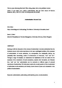
Dec 6, 2007 - Figure 17: A new business model for inter-domain roaming . ... FON, a Wi-Fi community alone has more than 190,000 hotspots around the ...
INTER-DOMAIN AUTHENTICATION FOR SEAMLESS ROAMING IN HETEROGENEOUS WIRELESS NETWORKS
by Summit Raj Tuladhar B.E. in Electrical and Electronics Engineering, Kathmandu University, 2003
Submitted to the Graduate Faculty of Information Sciences in partial fulfillment of the requirements for the degree of Master of Science in Telecommunications
University of Pittsburgh
2007
UNIVERSITY OF PITTSBURGH SCHOOL OF INFORMATION SCIENCES
This thesis was presented
by
Summit Raj Tuladhar
It was defended on December 6, 2007 and approved by
Dr. David Tipper, Associate Professor
Dr. Prashant Krishnamurthy, Associate Professor
Thesis Advisor: Dr. James B.D. Joshi, Assistant Professor
ii
Copyright © by Summit Raj Tuladhar 2007
iii
INTER-DOMAIN AUTHENTICATION FOR SEAMLESS ROAMING IN HETEROGENEOUS WIRELESS NETWORKS Summit Raj Tuladhar, MST University of Pittsburgh, 2007
The convergence of diverse but complementary wireless access technologies and inter-operation among administrative domains have been envisioned as crucial for the next generation wireless networks that will provide support for end-user devices to seamlessly roam across domain boundaries. The integration of existing and emerging heterogeneous wireless networks to provide such seamless roaming requires the design of a handover scheme that provides uninterrupted service continuity while facilitating the establishment of authenticity of the entities involved. The existing protocols for supporting re-authentication of a mobile node during a handover across administrative domains typically involve several round trips to the home domain, and hence introduce long latencies. Furthermore, the existing methods for negotiating roaming agreements to establish inter-domain trust rely on a lengthy manual process, thus, impeding seamless roaming across multiple domains in a truly heterogeneous wireless network. In this thesis, we present a new proof-token based authentication protocol that supports quick reauthentication of a mobile node as it moves to a new foreign domain without involving communication with the home domain. The proposed proof-token based protocol can also support establishment of spontaneous roaming agreements between a pair of domains that do not already have a direct roaming agreement, thus allowing flexible business models to be supported. We describe details of the new authentication architecture, the proposed protocol, which is based on EAP-TLS and compare the proposed protocol with existing protocols. iv
TABLE OF CONTENTS
PREFACE ..................................................................................................................................... X 1.0
INTRODUCTION ........................................................................................................ 1 1.1
BACKGROUND AND MOTIVATION ............................................................ 2
1.2
SCOPE OF RESEARCH .................................................................................... 4
1.3
PROPOSED APPROACH AND CONTRIBUTIONS ..................................... 5
1.4
THESIS ORGANIZATION ................................................................................ 6
2.0
LITERATURE SURVEY AND RELATED WORK ................................................ 8 2.1
SEAMLESS HANDOVERS ............................................................................... 8
2.2
AUTHENTICATION ........................................................................................ 10 2.2.1
Entity Authentication .................................................................................... 10
2.2.2
Message Authentication ................................................................................ 12
2.3
2.4
DESIRABLE PROPERTIES OF AUTHENTICATION ............................... 13 2.3.1
Mutual Authentication .................................................................................. 13
2.3.2
Privacy ............................................................................................................ 14
2.3.3
Resistance to Dictionary and Brute Force Attack ...................................... 14
2.3.4
Resistance to Replay Attack ......................................................................... 14
2.3.5
Use of Session Keys ........................................................................................ 14 AUTHENTICATION MODELS...................................................................... 15 v
2.5
AUTHENTICATION PROTOCOLS .............................................................. 16 2.5.1
Point-to-Point Protocol (PPP)....................................................................... 16
2.5.2
Extensible Authentication Protocol (EAP) .................................................. 17 2.5.2.1 EAP Packet Format ............................................................................ 18 2.5.2.2 EAP Protocol Overview ...................................................................... 20 2.5.2.3 EAP Pass-through ............................................................................... 21
2.5.3
EAP-TLS ........................................................................................................ 22
2.5.4
IEEE 802.1x.................................................................................................... 25
2.5.5
Remote Authentication Dial-In User Service (RADIUS) ........................... 27 2.5.5.1 RADIUS Messages .............................................................................. 27
2.6
ROAMING AND AUTHENTICATION ......................................................... 28 2.6.1
Authentication and Key Agreement Protocols ........................................... 29 2.6.1.1 Involvement of Home Network .......................................................... 29 2.6.1.2 Key Derivation..................................................................................... 30 2.6.1.3 Symmetric Key Based ......................................................................... 30 2.6.1.4 Public Key Certificate Based ............................................................. 30
3.0
2.6.2
Inter-Domain Authentication ....................................................................... 32
2.6.3
Handovers and Authentication..................................................................... 34
2.6.4
Handover Types ............................................................................................. 36
2.7
MEDIA-INDEPENDENT PRE-AUTHENTICATION ................................. 37
2.8
SHADOW REGISTRATION ........................................................................... 38
2.9
OPTIMISTIC ACCESS .................................................................................... 39 SEAMLESS ROAMING IN HETEROGENEOUS NETWORKS ....................... 41
vi
3.1
ROAMING AGREEMENTS ............................................................................ 41
3.2
EXISTING BUSINESS MODELS ................................................................... 42
3.3
SPONTANEOUS ROAMING .......................................................................... 45
3.4
A NEW BUSINESS MODEL FOR HETEREGENOUS WIRELESS
NETWORKS....................................................................................................................... 47 4.0
PROOF-TOKEN BASED APPROACH .................................................................. 51 4.1
PROTOCOL OPERATION ............................................................................. 52
4.2
PROTOCOL ANALYSIS AND COMPARISON ........................................... 59
CONCLUSION & FUTURE WORK........................................................................................ 62 4.3
PROTOTYPE IMPLEMENTATION – FUTURE WORK ........................... 63
APPENDIX A .............................................................................................................................. 64 BIBLIOGRAPHY ....................................................................................................................... 65
vii
LIST OF FIGURES
Figure 1: Handover Scenarios (a) Intra-Domain, Horizontal (b) Inter-Domain, Horizontal .......... 8 Figure 2: Three-party authentication model ................................................................................. 15 Figure 3: EAP Packet Format ....................................................................................................... 18 Figure 4: EAP Message Flow ....................................................................................................... 20 Figure 5: EAP Pass-Through ........................................................................................................ 21 Figure 6: EAP-TLS ....................................................................................................................... 22 Figure 7: 802.1x Architecture ....................................................................................................... 26 Figure 8: Public Key based Roaming ........................................................................................... 32 Figure 9: Challenge-Response based Inter-Domain Authentication ............................................ 33 Figure 10: Enhanced Challenge-Response based Inter-Domain Authentication .......................... 34 Figure 11: (a) Handoff in same administrative domain. (b) Inter-domain handoff ...................... 35 Figure 12: Cellular Regions .......................................................................................................... 38 Figure 13: Optimistic Access ........................................................................................................ 39 Figure 14: One-to-One Roaming (a) Cash Flow (b) Topology .................................................... 43 Figure 15: Broker Based Roaming (a) Cash Flow (b) Topology.................................................. 44 Figure 16: Business Model for Hotspots ...................................................................................... 44 Figure 17: A new business model for inter-domain roaming ....................................................... 48 Figure 18: Accounting Message Flow .......................................................................................... 50 viii
Figure 19: EAP-Token Method .................................................................................................... 54 Figure 20: Mobile Node's movement through Visited Domains .................................................. 56 Figure 21: Test bed Implementation ............................................................................................. 64
ix
PREFACE
I would like to take this opportunity to express my heartfelt gratitude to my thesis advisor Dr. James Joshi for his constant encouragement and support throughout my Masters studies. He has provided me the continuous guidance and motivation which has helped me in carrying out this research work. I would also like to thank the members of my thesis committee, Dr. Prashant Krishnamurthy and Dr. David Tipper for all their help and advice. I am grateful to Carlos E. Caicedo for his immense support and fruitful discussions which have helped me shape this project. I am also thankful to Craig Schenker for helping me in the implementation of this project. I would also like to acknowledge that this research was supported by the US National Science Foundation award IIS-0545912. Finally, my deepest regards go to my mother Ajeeta, my father Milan for their unconditional love and my wife Kiran for her patience and support. I dedicate this thesis to them.
x
1.0
INTRODUCTION
The Internet and wireless communication have evolved to change our perception of communication and computing. We expect to be able to access the internet and also communicate with friends and family at all times, whether sitting at home or traveling. With the growth of wireless access technologies and the rapid proliferation of mobile devices supporting internet access, it is possible to be always connected. According to the research firm Informa, at the end of November 2007, there were 3.3 billion mobile phone subscribers – equivalent to half the global population [1]. It is also estimated that global mobile phone penetration will rise to 90% by the end of 2010 [2]. The enabling technologies for such a global cellular infrastructure include GSM/GPRS, UMTS, and CDMA2000, which can deliver not only telephony services, but also high speed data. On the user side, most of the current handheld and portable devices like PDAs are built with multiple wireless interfaces. Laptops have built-in radio chipsets for IEEE 802.11 based Wireless LAN (WLAN) and optional radio interfaces for data connectivity using cellular networks. Academic institutions and commercial offices have enterprise-wide wireless network allowing their employees or students to have free access to the wireless networks. Hotspot operators offer internet connectivity in public places like airports, café‟s, hotels and gas-stations.
1
FON, a Wi-Fi community alone has more than 190,000 hotspots around the world [3], each of which operated by an individual sharing his home internet connection. A growing number of wireless technologies and increasing number of wireless providers of different sizes have truly created a heterogeneous wireless network with almost a global coverage. From a mobile user‟s perspective, it is highly desirable to have seamless connectivity allowing inter-operation of the different technologies and providers. This would allow global roaming and universal access with the convenience of having a single bill for all services.
1.1
BACKGROUND AND MOTIVATION
A mobile user desires to be “Always Best Connected” [4], which means the user is driven by a quest for higher speed and lower prices. The user also wants a ubiquitous coverage so that he can get access to network resources from anywhere, anytime. However, data rate and coverage are complementary to each other. Higher data rates are easier to provide for a smaller coverage. For example, a 3G network has a wider coverage but slower speeds; whereas Wireless LANs have higher speeds but smaller coverage. Thus, wide wireless network coverage with high data rates is not possible with a single technology and a single wireless provider. A heterogeneous wireless network will consist of wireless networks of multiple technologies operated by multiple service providers. A mobile user must be able to discover and select the best service provider at a given location [5]. As he moves in space and time, he must be able to seamlessly roam from one network to the other in a secure manner, being always connected to the best network. In particular, the solutions that support 2
such seamless roaming should ensure that the authenticity of the entities as it connects to the new domains is properly established. The work of this thesis is motivated by a vision of seamlessly roaming across administrative boundaries and wireless access technologies without the user ever knowing about the transitions. Such a seamless roaming requires that any active TCP connection is not broken and that the handover time is minimum. Service continuity in handovers is achieved by mobility management protocols like Mobile IP [6] and Mobile IPv6 [7], in which a Mobile Node (MN) is able to use its Home Address in a Foreign Network. Another crucial issue for seamless roaming is the handover delay that occurs as a mobile node moves from one network to the other. For a smoother transition, a minimum handover delay is desired. A key reason for a longer handoff delay in the existing solutions for secure, seamless roaming across administrative domains is the delay introduced by the authentication process. Such a delay is introduced because the currently employed authentication protocols require the participation of the home domain. Use of authentication protocols that do not involve the mobile node‟s Home Network and hence eliminate round-trip latencies could improve the speed with which the handover takes place in a secure manner. This research work has been motivated by such a need for improved authentication approaches that do not compromise the security of the handover process while eliminating latencies due to the participation of the home network.
3
1.2
SCOPE OF RESEARCH
With ongoing development in the field of mobile communication, we are close to the next-generation of mobile internet which promises to bring multimedia services in our mobile devices. However, for seamless internet connectivity with mobile devices as envisioned in all-IP networks [8], there are several challenges that need to be addressed first. As a mobile device moves into and out of the coverage of one wireless network to another wireless network, its Point of Attachment (PoA) to the internet changes. A change in the PoA creates a disruption, the length of which depends on whether the change in the PoA is across administrative domains and/or across varying radio technologies. In a conventional approach for inter-domain authentication, the home-domain is actively involved in authenticating all mobile nodes who are roaming to foreign domains. For example, for roaming users in GSM, a challenge response mechanism is carried out between the mobile device and the Authentication Center at its home network [9]. In fact, for all symmetric key based authentication mechanisms, the home domain must be involved, as the symmetric key is stored only at the home authentication server and the mobile device. The focus of this research work has been to develop authentication architecture with minimum handover latency which will be suitable for seamless roaming in future heterogeneous wireless networks. A key issue in such heterogeneous networks is also the possibility of roaming to administrative domains with which a mobile node‟s home domain does not have a preestablished roaming agreement. Furthermore, dynamic roaming agreements may need to be facilitated in such an environment to ensure seamless roaming. In this thesis, we explore a public-key, certificate-based solution to address the issue of authentication as a mobile node 4
roams from one domain to another that may or may not have pre-established roaming agreements.
1.3
PROPOSED APPROACH AND CONTRIBUTIONS
In the proposed approach towards inter-domain authentication, interaction with the home domain is discouraged during the authentication process. To authenticate two previously unknown entities, certificate-based authentication is used to verify the claimed identities. Since using certificates, two parties do not have to exchange secrets in advance, it is more suitable for roaming scenarios in heterogeneous wireless networks. However, the use of certificates for authentication requires a Public Key Infrastructure (PKI) with a common root Certificate Authority (CA). Previous proposals using certificate based authentication in wireless networks [10], [11], assume that all parties including the mobile node and the foreign Authentication, Authorization, and Accounting (AAA) server carry with it the certificate of the root CA, which is used as a trust anchor to establish new trust between the MN and the Foreign AAA. In our proposed work, we do not assume a common root CA, and each domain has its own root CA, removing the cost of expensive PKI infrastructure. Two domains cross-certify each other when they form a roaming agreement so that each domain has n Certificates if it has roaming agreements with n other domains. The certificates which are issued by partnering domains is known as a „Roaming Certificate.’
5
A Mobile Node carries with it a certificate issued by its home domain‟s CA and prooftokens which are similar to certificates, but they are issued by previous visited domain‟s CAs after successful authentications there. Whereas a certificate binds a subject‟s identity with a public key, a proof token additionally proves the fact that the subject was successfully authenticated at the issuer‟s domain at the issue time of the proof token. The Mobile Node uses this proof token to authenticate quickly to a domain which does not have a direct relationship with its home domain, but has a roaming agreement with a previous domain the Mobile Node had visited. If the previous visited domain had issued a proof-token for the Mobile Node, the MN stores the token locally in a structure known as a token-store, and uses the same proof-token to authenticate at a new wireless domain. With this proof-token based authentication mechanism, whenever, the MN is at a foreign domain, there is no need to involve the home domain during the time of authentication process. Accounting messages could be sent to the home domain only after the authentication process is complete. The Mobile Node thus gets a quicker network access with local authentication, which provides better „seamlessness‟ than existing methods.
1.4
THESIS ORGANIZATION
The research carried out for this thesis involved exploring various issues regarding seamless mobility in heterogeneous wireless networks, and it proposes a novel solution for an issue regarding re-authentication latency. The next four chapters of this thesis have been organized in the following order. Chapter 2 discusses work related to seamless mobility and does 6
a brief literature survey. Chapter 3 introduces the relation of inter-domain trust and roaming agreements. A new business and trust model is presented in this chapter on the basis of which the proof-token based authentication mechanism is described with protocol details in Chapter 4. Finally, in Chapter 5, a summary of contributions is listed and also mentions the ongoing prototype implementation of the proposed protocol. Some recommendations for future work is also presented at the end.
7
2.0
LITERATURE SURVEY AND RELATED WORK
2.1
SEAMLESS HANDOVERS
Traditionally, handovers in wireless networks were carried out by technology-specific mechanisms since it only involved intra-technology handovers such as Global System for Mobile Communications (GSM) to GSM or Universal Mobile Telecommunications System (UMTS) to UMTS. The handover between base stations or access points of the same wireless operator, known as intra-domain handover, is transparent to the IP layer. For roaming between wireless operators, inter-domain handovers are required, which involves Layer 3 handover as well.
Do
ma
in
B
UMTS
Do
ma
in
(a)
UMTS
(a)
WiFi
(b)
A
UMTS
(a)
UMTS
(d)
(c )
WiFi
(b) WiFi
(a)
WiFi
Figure 1: Handover Scenarios (a) Intra-Domain, Horizontal (b) Inter-Domain, Horizontal (c) Intra-Domain, Vertical (d) Inter-Domain, Vertical
8
The intra-technology handovers, either roaming or within the same domain is known as horizontal handovers as shown in Figure 1(a) and Figure 1(b). With the proliferation of portable devices with multiple wireless interfaces (GSM/UMTS, WiFi, WiMax) and the advent of software defined radios (SDRs), a more ubiquitous coverage and better throughput could be achieved with inter-technology handovers, also known as vertical handovers. Like horizontal handovers, vertical handovers could be within the same domain or between domains as shown in Figure 1(c) and Figure 1(d). In all cases, session continuity and minimal handover disruption time has always been the primary goals for seamless handover. The seamlessness is dependent on the service being provided. In pure voice networks such as GSM, seamlessness is perceived as delivering the voice service with bounded handover latency so that voice conversations are not disrupted. In General Packet Radio Service (GPRS)/UMTS networks offering data services as well, handover seamlessness requires continuity of a TCP session and minimizing packet losses. The goal of seamlessness is easier to achieve for intra-technology and intra-domain handovers. For example, UMTS supports macro-diversity, in which a mobile terminal can send/receive radio frames to/from more than one base stations (BSs) at the same time. Therefore, a mobile terminal can perform a „make-before-break‟ soft handover. Such capabilities are not supported for other technologies like wireless LANs (WLANs). The mobile terminal cannot be serviced in parallel by more than one access point (AP) and therefore has to break its communication with its current AP before establishing a connection with a new one. For an integrated wireless heterogeneous network environment a more generic approach would be to push the mobility management functionality from link layer to the network layer. It 9
can then serve as the rendezvous point for all underlying technologies. Therefore intertechnology vertical handovers are better treated at the IP layer. The IP gateway could be colocated with the radio-specific gateway, as in the Serving GPRS Support Node (SGSN) or Radio Network Controller (RNC) in the UMTS network. Seamless handovers become an even more challenging task if the radio communication is lost while switching between APs (e.g., switch from UMTS to WLAN radio communication or handover between WLAN APs belonging to different IP subnets). Several techniques can be employed to proactively take actions and establish state information in the involved Access Routers. In the following, a thorough analysis of the Mobile IPv6 (MIPv6) [7] and Fast MIPv6 [5] protocol operation is provided focusing on their contributing factors to handover delay. The degree of enhancements offered by Fast MIPv6 operation is dependent on the timely availability of handoff-related information. Link layer triggers assist in the IP handover preparation and execution phases targeted at optimal synchronization of layer 2 and 3 handovers.
2.2
AUTHENTICATION
2.2.1 Entity Authentication
Whenever two entities are communicating with each other, each entity should have an assurance that the other entity is legitimate and it is who it claims it is. The process by which a system verifies the identity of an entity is known as authentication. The entity could be a device or a user. 10
Authentication consists of two acts: providing the proof of authenticity and verifying the proof. This can be achieved broadly in two ways:
When the two entities share a common secret key, symmetric key cryptography is used to prove and verify the identities.
When the two entities do not know each other in advance, public key cryptography is used in which each entity has a public private key pair. The nature of these keys is such that a message encrypted with a private key can only be decrypted with a public key and vice versa. The possession of the private key corresponding to the public key as bound in the certificate proves one‟s identity. The certificate is signed by the trusted third party between the two entities which help in establishing the proof of authenticity of the entities. This involves a Public Key Infrastructure (PKI) with a root Certificate Authority that everyone trusts and issues certificates.
Authentication must be performed at the initial stage of communication. After the identity of an entity is established via authentication, a decision can be made about proper authorization for a particular resource by using access control mechanisms. If required, such authorization for a resource can be accounted for billing purposes as well. The authentication, authorization, and accounting processes are popularly known as the AAA processes. After completing the authentication process, the two parties should perform a key exchange protocol to establish shared secrets for encrypting a secure channel between them.
11
2.2.2 Message Authentication
While device or user authentication ensures that the two points of communication are legitimate, message authentication ensures and verifies the integrity of the data being communicated. Message authentication is required so that the receiver of the message can be sure that the information included in the message has been produced by a legitimate source and has not been altered by other parties in transit. This is generally known as data integrity protection. Unlike device or user authentication which is performed at the beginning of communication, message authentication needs to be done for all messages. This prevents malicious and intended corruption of data by the so called man-in-the-middle (MITM) trying to tamper the data. Message authentication is different from cyclic redundancy checks (CRC) designed to mitigate random natural data corruption caused by impediments in the physical communication channel. The CRC cannot mitigate intended corruption as the man-in-the-middle can recalculate the CRC value and put a correct CRC checksum for the tampered message. Thus, a separate message authentication code (MAC) is appended to the message to prevent the MITM attack on a message. A MAC algorithm accepts as input a secret key and an arbitrary-length message to be authenticated, and outputs a MAC (also known as a message digest). At the other end of communication, a verifier possessing the secret key can detect any changes to the message content by performing the same MAC algorithm.
12
2.3
DESIRABLE PROPERTIES OF AUTHENTICATION
In this section, we describe some desirable properties for entity authentication:
2.3.1 Mutual Authentication
Conventionally for wired networks, a client device or user trusts the wired network it is connecting to, say a dial-up ISP, and the authentication is unilateral. In such a case, only the client proves its identity to the network, and the authenticity of the network is not verified by the client assuming a trustworthy network. This assumption might be true for some cases, but it is questionable in a multi-access network, especially a wireless network. A malicious node can exploit the assumption of a trustworthy network by launching an MITM attack in which a malicious node intercepts and modifies the authentication messages and tricks a client into thinking that the malicious node is actually the server it wants to talk to. It also fools the server into thinking that it is the client it is talking to. MITM attack can be prevented if the client and the server both authenticate each other, which is known as mutual authentication. The client-server mutual authentication is a special case of a more generic concept of mutual authentication, where two parties are simply peers and each peer authenticates the other either sequentially or in parallel.
13
2.3.2 Privacy
A malicious node should not be able to determine the identity of an authenticating node by listening to the authentication messages.
2.3.3 Resistance to Dictionary and Brute Force Attack
A malicious should not be able to decipher the encrypted data by a dictionary attack or perform a brute force attack within a reasonable amount of time.
2.3.4 Resistance to Replay Attack
In a replay attack, a malicious node records the authentication message and plays it back at a later time. In doing so, the malicious node should be able to authenticate itself by simply replaying the messages.
2.3.5 Use of Session Keys
A fixed key should not be used for encryption/decryption or message integrity check values. Fresh cipher and integrity keys should be generated for each session. Doing so, even if an eavesdropper breaks previous encryption keys, he will not be able to break the new session keys.
14
2.4
AUTHENTICATION MODELS
In a two-party authentication model, two peers authenticate each other via interacting in a direct line of communication without the involvement of any other nodes. An example could be of a client server authentication. However, with increasing size of networks and a large number of clients trying to access the network and its services, a more scalable solution is a three party model (Figure 2: ) in which the database required for authentication, authorization and accounting (AAA) and the AAA process itself is carried out by a central entity known as an AAA server and a large number of low-cost unsophisticated network access servers (NAS) provides the actual access to the network.
Supplicant
Access Link Protocol
Authenticator (NAS)
AAA Protocol
Authentication Server
Service Provider Network
Figure 2: Three-party authentication model
The three parties involved are as follows. 1. Supplicant: The device or the user who requests for access to the network. An example could be a mobile device trying to connect to a wireless network. 2. Authenticator: This is an edge device in the service provider network which controls access to the network. It allows or denies network access after consulting with the authentication server using an AAA protocol like RADIUS [12] or Diameter [13]. An authenticator is also 15
known as a Network Access Server (NAS). An example of an authenticator is the access point of a wireless network. 3. Authentication Server: The authentication server is a more secure device which has a database containing the credentials of all the users and which provides AAA services. It is usually a central high-end server capable of providing authentication services for a large number of authenticators. The communication channel between the authenticator and the authentication server is over a trusted network, and can be protected via pre-established shared secret keys. Some examples of AAA servers are RADIUS and Diameter servers.
2.5
AUTHENTICATION PROTOCOLS
2.5.1 Point-to-Point Protocol (PPP)
The Point-to-Point Protocol [14] is a data link layer protocol designed to establish a direct connection between two nodes over simple links like a serial cable, a phone line, a trunk line, or fiber optic links. It is popularly used by Internet Service Providers (ISPs) for dialup internet access. PPP includes three phases for setting up a connection:
1. Link Control Protocol (LCP) Phase: In this phase, the two ends of the link negotiate link parameters like maximum frame size and link speed. It also allows for the two parties to negotiate a mechanism for authentication to be performed in the next phase.
16
2. Authentication Phase: The PPP end-point can authenticate the supplicant directly or act as a mediator and pass the authentication credentials to an AAA server. Originally, PPP supported only two authentication mechanisms: Password Authentication Protocol (PAP) [15] and Challenge Handshake Authentication Protocol (CHAP) [16]. PAP is an insecure authentication mechanism in which the password is sent in clear text whereas CHAP uses a Challenge-Response mechanism for authentication. 3. Network Control Protocol (NCP) Phase: In this phase, the network layer parameters such as IP addresses are configured.
In PPP, the authentication mechanism negotiated in the LCP phase is very limited, and to add a new method or algorithm requires the change of the network end points.
2.5.2 Extensible Authentication Protocol (EAP)
EAP [17] is an extension to the PPP protocol and is regarded as a generic authentication framework for transport of methods that authenticate two parties. It is frequently used in pointto-point connections and wireless networks. It is not limited to any specific authentication method, but supports various authentication methods. It is also extensible and new method could be defined. Some of the popular EAP methods are EAP-MD5 [17], EAP-TLS [18], EAP-TTLS [19], EAP-PSK [20], EAP-IKEv2 [21], EAP-SIM [22], EAP-AKA [23], and EAP-PEAP [24]. Although originally designed as an extension to PPP, EAP can run on top of various other protocols like IEEE 802.1x EAPoL, PANA, PKM-EAP (Privacy Key Management – EAP), RADIUS, Diameter. 17
The primary purpose of EAP is network access control, which is enforced using a keygenerating method. An EAP keying hierarchy is defined with two keys that are derived at the top level: the Master Session Key (MSK) and the Extended MSK (EMSK). In the most common deployment scenario, a peer and a server authenticate each other through a third party known as the authenticator. The authenticator or an entity controlled by the authenticator enforces access control. After successful authentication, the server transports the MSK to the authenticator; the authenticator and the peer derive transient session keys (TSK) using the MSK as the authentication key or a key derivation key and use the TSK for per-packet access enforcement.
2.5.2.1 EAP Packet Format The frame format of an EAP packet is shown in as Figure 3.
Success/Failure Packet Format
Code (1 byte)
ID (1 byte)
Length (2 Bytes)
Request/Response Packet Format
Code (1 byte)
ID (1 byte)
Length (2 Bytes)
Type (1 byte)
Expanded Type Request/Response Packet Format
Code (1 byte)
ID (1 byte)
Length (2 Bytes)
0XFE
Data (0+ Bytes)
Vendor-ID (3 Bytes)
Vendor-Type (4 Bytes)
Data (0+ Bytes)
Figure 3: EAP Packet Format
Code: The Code field identifies the type of EAP packet. EAP Codes are assigned as follows: 1 – Request 2 – Response 18
3 – Success 4 – Failure
Identifier: The Identifier field aids in matching responses with requests.
Length: The Length field indicates the length of the EAP packet including the Code, Identifier, Length and Data fields.
Type: Present only for Request and Response messages. It defines the actual type of authentication method to be used. Some examples are: 0x01 – Identity 0x02 – Notification 0x03 – Negative Acknowledgement 0x04 – MD5 Challenge 0x05 – One Time Password etc.
For Type=0xFE, the type space is expanded to a 3 byte Vendor ID and a 4 byte Vendor Type. Vendor ID=0 is reserved for IETF specific EAP types, whereas for other Vendor IDs, the vendors can develop a proprietary authentication type.
Data: Present only for Request and Response Code types, the data field contains information necessary for the authentication.
19
2.5.2.2 EAP Protocol Overview
Authenticator (NAS)
Supplicant
Authentication Server
Request/Identity Response/Idenity
Response
Request
Request
Response
Response
Request
Request
Response
Response
Request
Request
Response
Response Success
Success Access Allowed
Figure 4: EAP Message Flow
As illustrated in Figure 4, the EAP protocol works as follows: 1. The authenticator sends a request to the peer that wants network access. The type field for this first message is typically set to „request for identity‟. 2. The peer sends a response packet back to the authenticator with a type field set to identity. 3. If the authenticator needs more information from the peer, it sends other request packets and the peer responds with response packets. This request and response process is repeated until the authenticator has enough information to authenticate the peer. 20
4. The authenticator sends EAP success or EAP failure message to the peer according to the outcome of the authentication process.
2.5.2.3 EAP Pass-through Typically the communication from the EAP peer to the authenticator runs over protocols such as PPP 802.1x (EAPOL), PANA, or PKM. From the authenticator to the authentication server, typically either RADIUS or Diameter is used. The authenticator just passes the EAP message and relays it from a Layer 2 protocol (typically) from the supplicant and to the authentication server using a higher layer protocol. This is illustrated in Figure 5.
EAP Methods
EAP Methods
EAP-TLS
EAP-TLS
EAP-TTLS
EAP-TTLS
EAP-SIM
EAP-SIM
EAP-AKA
EAP-AKA
PEAP
PEAP
EAP
PPP
Supplicant
EAP
EAP Messages
802.1x PANA
PPP
Authenticator
802.1x PANA
(EAP Pass-Through)
PKM-EAP
(RADIUS/ Diameter)
PKM-EAP
Authentication Server
EAP Peer
Figure 5: EAP Pass-Through
21
2.5.3 EAP-TLS
EAP-TLS [18], is an EAP method defined in RFC 2716 based on TLS [25].
Client
Server EAP-TLS-Start
Generate ClientRandom
ClientHello (Version, CryptoSuite, ClientRandom) Generate ServerRandom
ServerHello (Version, CryptoSuite, ServerRandom)
Server-Certificate Check Server Certificate & Store KU-S
Client-Certificate-Request Server-Done
Client-Certificate Check Client Certificate & Store KU-C Generate Random Number Pre-Master-Secret (PMS) Calculate & Store Master Secret MS = prf (PMS, ClientRandom, ServerRandom)
Client-Key-Exchange Calculate & Store Master Secret MS = prf (PMS, ClientRandom, ServerRandom)
Client-Certificate-Verify Changed-Cipher-Specs Finished Changed-Cipher-Specs Finished
EAP-Success Figure 6: EAP-TLS
22
The sequence of EAP-TLS handshake messages negotiated is illustrated in Figure 6. On receiving the TLS-Start message from the server, the client responds with a ClientHello message, which contains:
Version Number: The client sends the version number corresponding to the highest version it supports. Version 2 is used for SSL 2.0, version 3 for SSL 3.0, and version 3.1 for TLS. Although the IETF RFC for TLS is TLS version 1.0, the protocol uses 3.1 in the version field to indicate that it is a higher level (newer and with more functionality) than SSL 3.0.
ClientRandom: A 4-byte random number that consists of the client‟s date and time plus a 28byte randomly generated number that will ultimately be used with the server random value to generate a master secret from which the encryption keys will be derived.
Cipher Suite: A list of cipher suites available on the client. An example of a cipher suite is TLS_RSA_WITH_DES_CBC_SHA, where TLS is the protocol version, RSA is the algorithm that will be used for the key exchange, DES_CBC is the encryption algorithm (using a 56-bit key in CBC mode), and SHA is the hash function.
Compression Algorithm: The requested compression algorithm.
The Server then responds with a ServerHello Message which consists of
Version Number: The server sends the highest version number supported by both sides. This is the lower of the highest version number the server supports and the version sent in the Client Hello message.
ServerRandom: A 4-byte random number that consists of the server‟s date and time plus a 28-byte randomly generated number that will be ultimately used with the client random value to generate a master secret from which the encryption keys will be derived. 23
Cipher Suite: The server will choose the strongest cipher that both the client and server support. If there are no cipher suites that both parties support, the session is ended with a “handshake failure” alert.
Compression Algorithm: Specifies the compression algorithm to use.
After exchanging the hello messages, the server sends the following messages:
Server Certificate: The server sends its certificate to the client. The server certificate contains the server‟s public key. The client will use this key to authenticate the server and to encrypt the premaster secret.
Client Certificate Request: The server requests authentication of the client.
Server Hello Done: The server tells the client that it is finished and awaiting a response from the client.
After receiving the Server Hello Done message, the client responses to server with the following messages:
Client Certificate: The client sends its certificate to the server for client authentication. The client‟s certificate contains the client‟s public key.
Client Key Exchange: The client generates a random number, the Pre-Master Secret (PMS), which it sends to the server by encrypting it with the public key from the server‟s certificate. Using the PMS, and ServerRandom and ClientRandom, both parties compute the Master Secret locally using a pseudo random function (prf). If the server can decrypt PMS and complete the protocol, the client is assured that the server has the correct private key. This step proves the authenticity of the server. 24
Certificate Verify: The client uses its private key to sign a hash of all the messages up to this point. The recipient verifies the signature using the public key of the signer, thus ensuring it was signed with the client‟s private key.
Change Cipher Spec: This message notifies the server that all messages that follow the Client Finished message will be encrypted using the keys and algorithms just negotiated.
Client Finished: This message is a hash of the entire conversation to provide further authentication of the client.
The server sends the final response to the client which consists of
Change Cipher Spec Message: This message notifies the client that the server will begin encrypting messages with the keys just negotiated.
Server Finished Message: This message is a hash of the entire exchange to this point using the session key and the MAC secret. If the client is able to successfully decrypt this message and validate the contained hashes, it is assured that the SSL/TLS handshake was successful, and the keys computed on the client machine match those computed on the server.
2.5.4 IEEE 802.1x
IEEE 802.1x [26] is a link layer standard for a port-based network access control mechanism. A port is where a device attaches to the network. For a wireless connection, it could be the first point of attachment, like an access point. Providing network access control at the port level ensures that only authenticated devices get access.
25
802.1x encapsulates EAP messages and carries them from the supplicant to the authenticator. Thus, it is also known as EAP over LAN (EAPoL). The architecture of 802.1x is shown in Figure 7.
Supplicant PAE
802.1x
Authenticator PAE
AAA Protocol
Authentication Server
Network Switch
PAE: Port Access Entity
Figure 7: 802.1x Architecture
The switch as seen in Figure 7 is controlled by the Authenticator PAE. It is open by default and is closed only after successful authentication. When the switch is open, only EAP messages are allowed, and all other traffic is blocked. When authenticating, the authenticator first asks the supplicant‟s identity via an EAP/Request-Identity message, and the supplicant sends its identity by sending an EAP/Response-Identity message. These messages are carried by 802.1x. The authenticator talks to the AAA server by relaying the EAP messages from the supplicant to the authentication server over AAA protocols like RADIUS and Diameter. The supplicant can be authenticated using any of the various EAP methods. Once authenticated, the authenticator closes the switch and the supplicant is granted access to all network resources.
26
2.5.5 Remote Authentication Dial-In User Service (RADIUS)
The Remote Authentication Dial-In User Service (RADIUS) is an industry standard protocol [12], [27] to provide authentication, authorization, and accounting services. Typically it is used for the communication between an authenticator and an authentication server. It uses the client server model, the authenticator (NAS) is the RADIUS client and the AAA server is the RADIUS Server. Messages exchanged between the server and the clients are authenticated using a pre-established shared secret key. The RADIUS standard support the use of RADIUS proxies. A RADIUS proxy is a device that forwards RADIUS messages between RADIUS-enabled devices.
2.5.5.1 RADIUS Messages RADIUS uses User Datagram Protocol (UDP) for sending the messages. UDP port 1812 is used for RADIUS authentication messages and UDP port 1813 is used for RADIUS accounting messages. Each RADIUS message consists of a header and zero or more attributes. Each RADIUS attribute specifies a piece of information about the connection attempt. Some examples of RADIUS attributes are user name, user password, type of service requested, IP address of the access server, etc. RADIUS attributes are used to convey information between RADIUS clients, RADIUS proxies, and RADIUS servers. The following RADIUS message types are defined:
Access-Request: Sent by a RADIUS client to request authentication and authorization for a connection attempt.
27
Access-Accept: Sent by a RADIUS server in response to an Access-Request message. This message informs the RADIUS client that the connection attempt is authenticated and authorized.
Access-Reject: Sent by a RADIUS server in response to an Access-Request message. This message informs the RADIUS client that the connection attempt is rejected. A RADIUS server sends this message if either the credentials are not authentic or the connection attempt is not authorized.
Access-Challenge: Sent by a RADIUS server in response to an Access-Request message. This message is a challenge to the RADIUS client that requires a response.
Accounting-Request: Sent by a RADIUS client to specify accounting information for a connection that was accepted.
Accounting-Response: Sent by the RADIUS server in response to the Accounting-Request message. This message acknowledges the successful receipt and processing of the Accounting-Request message.
2.6
ROAMING AND AUTHENTICATION
One of the challenges for seamless roaming is that a Mobile Node (MN) and a Foreign Network (FN) must mutually authenticate each other without any prior trust relationship between them. The authentication is possible only if there is a trust relationship between MN‟s Home Network (HN) and FN. Then upon roaming, the following steps should be taken:
28
Negotiation of Security Mechanism: MN and FN must negotiate a common cipher suite, which includes Authentication and key exchange algorithm, encryption and decryption algorithm, and hash functions.
Mutual Authentication: FN must prove to MN that it is authorized to provide MN its services. MN must also prove to FN that it is authorized by HN to use FN‟s services.
Key Agreement: The AAA server in FN (AAAF) and the MN must agree upon a Master Session Key with which they can derive cipher and integrity protection keys.
2.6.1 Authentication and Key Agreement Protocols
The authentication and key agreement protocols for roaming scenarios can be implemented in a number of ways.
2.6.1.1 Involvement of Home Network HN‟s interaction in the authentication of MN in FN can either be online or offline. In the offline case, HN has to provide FN some security related information so that it can authenticate the MN. Offline involvement of HN makes the authentication algorithm efficient, as no round trips to the HN are required. In an online involvement, HN participates in the authentication of MN in FN. Hess & Schafer showed that for a full authentication dialogue involving the entities of the HN, the delay experienced by a MN is largely determined by the end-to-end delay between the FN and the HN
29
[36]. Thus, it is desirable to have HN involved for only a few message exchanges to minimize the number of round-trips to HN and the authentication delay.
2.6.1.2 Key Derivation After the authentication is completed, the MN and the FN must establish a master key, from which cipher and integrity keys are derived subsequently. If the HN is involved in the authentication, the master key can be derived either by the HN or the FN. If it is derived by the HN, it needs to send it to FN in a secure channel.
2.6.1.3 Symmetric Key Based In a symmetric key based authentication and key agreement protocol, the MN and HN share a common key between them. When MN is roaming in FN, authentication messages are relayed by FN to HN over a secure channel. The authentication and authorization steps are done at the HN, which involves a number of message exchanges between the MN and HN. The result of the authentication and authorization is sent to FN over the secure channel, and FN allows or denies network access accordingly.
2.6.1.4 Public Key Certificate Based According to Long, Wu, & Irwin [39], Public-key based authentication is more suitable for roaming scenarios since with public key certificates, two parties can mutually authenticate each other without requiring any prior trust relationship between them, and without the visited network connecting to the home network of the MN.
30
However, there are some difficulties associated with public key certificates regarding certificate validation. Both MN and AAAF must validate each other‟s certificates during the mutual authentication. This involves verifying the CA‟s signature on the certificates and checking their revocation status. If we assume that MN‟s and FN‟s certificates are signed by a common CA trusted directly by both parties, the certificates can be validated easily. If there is no direct trust relationship, both MN and FN require a chain of certificates with a common root CA as the trust anchor between MN and FN. The construction of this certificate path requires certificate retrieval from several CAs until a trust anchor is reached. Further, revocation status of these certificates must also be retrieved. However, MN does not have internet access during the authentication phase to validate the certificate chain or to retrieve a revocation list. A first approach in solving this problem is that in the beginning, the MN could carry out the authentication protocol without performing the certificate path verification of FN‟s certificate. Once MN gets an internet connection, it can perform the certificate path validation and revocation lists can be checked to verify the authenticity of certificates. In a second approach, as suggested in [10], MN could delegate the validation of FN‟s certificate to a trusted third party. The MN only needs to be sure of the revocation status of the trusted third party. However, with large number of mobile nodes, the load at the trusted third party increases, delaying authentication. In Figure 8, Domain F has direct roaming agreements with Domain A and Domain B. While the roaming agreements are negotiated, the domains cross certify each other, Thus, Domain F stores certificates issued b Domain A and Domain B.
31
Domain A AAAH
Domain B
CA
CA
A
AAAH
B
Domain F A
B
AAAF
MN1
MN2
Figure 8: Public Key based Roaming
The Mobile Node, MN1 has a subscription from Domain A, and carries with it a certificate issued by Domain A. Similarly MN2 from Domain B has a certificate issued from Domain B. Both MN1 and MN2 can authenticate in Domain F with their certificates using a standard TLS authentication algorithm. AAAF uses A while authenticating MN1 and B while authenticating MN2.
2.6.2 Inter-Domain Authentication
Consider a mobile node trying to connect to a foreign wireless network (Domain A) having a roaming agreement with its home network (Domain H). The authenticator in domain A requests the identity of the MN, and the MN presents its Network Access Identifier (NAI) [28], 32
which has a form of user@domain. The AAA in Domain A (AAAF-A) looks at the domain part of the NAI and sees that the MN does not belong to its administrative domain. It then checks if it has roaming agreements with MN‟s home domain, and if it does, it sends a message to the AAA at the MN‟s home domain (AAAH). For a shared secret based authentication, AAAH performs a challenge-response authentication and sends an Accept or a Reject message as an outcome of the authentication. MN
Authenticator
AAAF-A
AAAH
Request ID NAI
NAI
NAI
Challenge
Challenge
Challenge
Response
Response
Response
Accept/ Reject
Accept/ Reject
Accept/ Reject
Figure 9: Challenge-Response based Inter-Domain Authentication
As shown in Figure 9, this method consists of two round-trips to the home domain. Since the home domain could be situated across the globe, it is desirable to minimize the number of round trips to the home domain. An enhanced Challenge-Response based inter-domain authentication method is shown in Figure 10, where the Challenge is generated locally at the authenticator, and the { NAI || Challenge || Response } triplet is carried to the AAAH which checks the response for that particular challenge and sends an accept or a reject message back. The enhanced Challenge Response mechanism only requires a single round trip to the Home Domain.
33
MN
Authenticator
AAAF-A
AAAH
Request ID NAI Challenge Response
NAI || Challenge || Response
NAI || Challenge || Response
Accept/ Reject
Accept/ Reject
Accept/ Reject
Figure 10: Enhanced Challenge-Response based Inter-Domain Authentication
The two methods shown above are simplified just to illustrate the number of round trips that may be required for an authentication to be performed by the home domain. In reality, depending on technology, the number of round trips required might be more. Various EAP methods could be used for authentication. For example, EAP-SIM for GSM, EAP-AKA for UMTS, PEAP, LEAP, EAP-TLS, or other flavors of EAP might be used for WLANs. More Round trips to the Home AAA will be required for setting up the session keys. Such a fullauthentication method will cause a large delay for the MN to get access to the network.
2.6.3 Handovers and Authentication
As a Mobile Node moves, it will come across various wireless networks. Handovers from one wireless operator to another might be one of two cases as depicted in Figure 11.
34
Home Domain
AAAH
Foreign Domain (A)
Home Domain (H)
Home Agent (HA)
AAAH
Home Agent (HA)
Foreign Domain (A)
Foreign Domain (B)
AAAF-A
AAAF-B
Authenticator A
Authenticator B
Point of Attachment A
Point of Attachment B
AAAF-A
Authenticator 1
Authenticator 2
Point of Attachment 1
Point of Attachment 2
Subnet 1
Subnet 2
MN
MN
(a)
(b)
Figure 11: (a) Handoff in same administrative domain. (b) Inter-domain handoff
In Figure 11, the MN might be moving across two networks in the same domain (case a) or between two different administrative domains (case b). In the first case, when the MN moves from Point-of-Attachment-1 (PoA-1) to PoA-2 in the same domain, a full-authentication may not be required. Depending on the technology being used, the Intra-domain handover might only involve Layer 2 handovers. Even if the two PoAs are in different subnets of the same domain, an Inter-Access-Point-Protocol (IAPP) or its equivalent can help transfer the security context from one PoA to the other. Within the same domain, a proactive distribution of keys to neighboring PoAs is also possible as seen in the work of Mishra in [29]. However, when the MN handovers to a wireless network in a different domain (case b), a security context transfer, or a proactive distribution of keys may not be possible due to firewall
35
security policies and different technologies that might be used. The MN has to perform a fullauthentication involving multiple round trips to the home domain, once it is in Domain B. For seamless roaming, the re-authentication delay at Domain B needs to be minimized.
2.6.4 Handover Types
Different authentication mechanisms are possible depending on the scenario. 1. Predictive Handover: In a predictive handover, the MN is aware of a possible disconnection from the current PoA in the near future and it has enough time to discover and select candidate networks to be its next PoA before getting disconnected. The mobility management layer of the MN receives Layer 2 Triggers [30] which notify it to take proactive steps for a quicker handover. If the MN can find out which network it is going to connect to next, it can establish an IPSec tunnel to the Access Router of the network proactively and pre-authenticate itself before actually moving into that network. This has been proposed in the Media Independent Pre-Authentication (MPA) draft [31]. Another approach for a predictive handover is to proactively distribute [29] the keys to all neighboring Access points. Non-predictive Handover: In a non-predictive handover, the MN is not able to get any warning about possible future disconnection. It cannot take proactive measures for a smoother handover to a new wireless network. In such a case, pre-authentication mechanisms do not work. When it roams to a new wireless network, it has to perform a full authentication which will involve multiple messages to the Home AAA server.
36
2.7
MEDIA-INDEPENDENT PRE-AUTHENTICATION
MPA [5] is a mobile-assisted higher-layer authentication, authorization and handover scheme that is performed prior to establishing layer 2 associations to a network (where mobile may move in near future). It provides a secure and seamless mobility optimization that works for inter-domain handover and heterogeneous handover involving both single interface and multiple interfaces.
MPA is a set of techniques / algorithms that are executed to ensure seamless
handover and connectivity to the target network by performing pre-configuration and preauthentication to the target network before the actual handover takes place. It can be used to enhance the performance of existing mobility protocols by performing the proactive layer 3 and layer 4 associations and bindings before the actual handover actually takes place, thereby saving time for these operations that usually take place after the layer 2 association. Even the layer 2 handover is enhanced by suppressing the 802.11 AP channel scanning and best AP selection at the interface driver by having prior information of the channel number of the selected target network SSID (done for the sake of a proof of concept). So association to the target network avoids channel scanning, detection of the PoA MAC address and appropriate channel selection.
Figure 1 briefly demonstrates different functional components that are part of media independent pre-authentication and provide proactive pre-authentication, pre-configuration and proactive handover tunneling techniques. Details of these functional components and their operation can be found in reference [5].
37
2.8
SHADOW REGISTRATION
In the Shadow Registration method [37], a security association is established between the MN and every neighboring AAA server before the MN handovers to the region controlled by the AAA server. This procedure operates like the shadow as one walks, thus the name – Shadow Registration.
Figure 12: Cellular Regions
A simplified model is shown in Figure 12, where the MN residing in the core, sends a registration request with AAA servers in all neighboring cells. The registration will already be completed when the MN moves to a particular call, and the only necessary AAA operations that are required will be processed locally in the new domain without communicating with the MN‟s home domain.
38
With a similar concept, Han et al. [38], have proposed Region-based Shadow Registration (RSR) which tries to increase the efficiency of Shadow Registration by performing a Shadow Registration only when the MN moves to a section with high probability of handoff. When the MN is near a cell core, no Shadow Registration is performed. As shown in Figure 12, the immediately following outer zone of the core cell is divided in three regions and each region is adjacent to two neighboring cells; when the MN moves to one of these three regions, a Shadow Registration is performed for the two neighboring cells. For example, when the MN moves from the Core to Region B, a Shadow Registration procedure is performed with cells 3 and 4.
2.9
OPTIMISTIC ACCESS
Aura and Roe [40] have proposed the Optimistic Access scheme of network access control to minimize the authentication delay. Instead of executing a stronger higher-delay authentication mechanism during the handoff process, the MN is granted optimistic access to the new network. The strong authentication is delayed until the handoff is actually completed.
MN’s Arrival
Access Authorized
Optimistic Access
Authorized Access
Figure 13: Optimistic Access
39
As shown in Figure 13, when the MN handoffs to the new network, a faster but weaker authentication takes place, and after it is successful the MN is authorized for an optimistic access to the new network. When the layer 2 handoff process is complete, the MN must be involved in a new stronger authentication to continue using the resources of the new network. After the end of this authentication the Optimistic Access scheme completes its purpose. The weaker authentication mechanism does not require any communication with the home network of the MN, thus making the optimistic access a fast authentication mechanism. However, security can be easily compromised with optimistic access, and it might be suitable for private networks where people are more trustworthy. For less secure applications, optimistic access is not recommended as it creates a window of opportunity for malicious users to try to exploit vulnerabilities. Thus, authentication using Optimistic access is a tradeoff between security and performance.
40
3.0
SEAMLESS ROAMING IN HETEROGENEOUS NETWORKS
3.1
ROAMING AGREEMENTS
For mobile users to be able to roam into foreign networks, the foreign network and user‟s home network must trust each other and have a roaming agreement established beforehand. While establishing a roaming agreement, two wireless service providers must agree upon a number of parameters including the services roaming users will be able to use, authentication and key agreement procedures, cipher suites to be used, etc. The number and type of parameters to be agreed upon depends upon the nature of their businesses. If they are non-commercial entities like two academic departments of a university, billing and charging functions might not be included in the roaming agreement. However, if the two entities are commercial service providers, an agreement on charging and billing and legal terms between them is necessary so that the foreign network is legally assured that it will be paid for its services and also the home network is assured that its customers will securely and seamlessly be able to use the services they have paid for. A wireless service provider may choose to establish roaming agreements with other wireless service providers so that it can offer networking services to its subscribers in a wider area than it can with only its own network coverage. When a user registers for a subscription from a wireless service provider, he accepts the service provider as its Home Network (HN). 41
During the registration process, he exchanges authentication credentials with its HN, and agrees upon a roaming profile which includes a list of services the user has subscribed to. The roaming profile also contains a list of other service providers with which the user can use roaming service. The credentials established with his home network will enable the user to not only access the network operated by its home provider, but also the ones operated by the roaming partners of its home network. However, the user conducts financial transaction only with its home network provider and he does not need to pay directly to any other roaming providers with which he has used service from.
3.2
EXISTING BUSINESS MODELS
In the wireless networking business, a distinction needs to be made between network provisioning and service provisioning. A Network Provider sets up a wireless network and it owns and operates the network. The role of a service provider is to attract customers into buying a subscription for wireless network access. The customers deal only with the service provider, in that they pay the service provider for getting network access from a given network operator. Traditionally wireless network providers have been few in number in a given area because of heavy initial investment on wireless equipment and spectrum licensing. Big telecom companies with wide market presence would act both as a network provider and a service provider with their own customer base. For example GSM/GPRS and UMTS wireless network providers have their own direct customers. In such traditional wireless networks, two service
42
providers could establish roaming agreement in a one-to-one basis (Figure 14) or a broker might be involved (Figure 15). Domain B
Domain A
Service Network Provider Operator
Service Network Provider Operator
Service Usage
User
Payment Roaming Agreement
(a)
(b)
Figure 14: One-to-One Roaming (a) Cash Flow (b) Topology
In Figure 14, the user has a subscription with domain A, making it the user‟s home domain. When the user roams to Domain B, he will still be billed in his home domain. Assuming a direct roaming agreement between Domain A and Domain B, Domain A would pay roaming charges to Domain B directly. However, if there is no direct roaming agreement and a broker is involved as an intermediary as shown in Figure 15, accounting messages will go through the broker, and the broker settles and clears all billing charges between the domains. The service and network model for new wireless technologies like Wi-Fi may have a different business model. Since WiFi operates over unlicensed spectrum, and equipment cost is not that large, a significant investment is not required to open up a wireless hotspot to serve niche markets like customers in shopping malls, airports, cafés, hotels, restaurants, and gas stations. Such hotspot operators may not have their own direct customers, but they would make roaming agreements with one or more hotspot aggregators like weroam.com, ipass.com, or trsutive.com. The hotspot aggregators are like brokers with an additional role of a service 43
provider. They sell service to the customers and pay the network operators for the actual network usage. Roaming Platform (Broker)
Domain B
Domain A
Service Network Provider Operator
Service Network Provider Operator
User Service Usage Payment Roaming Agreement
(a)
(b)
Figure 15: Broker Based Roaming (a) Cash Flow (b) Topology
Service Provider Roaming Platform (Broker)
Network Operator 1
Network Operator n
User
Figure 16: Business Model for Hotspots
In Figure 16, the user has a subscription with the broker which sends monthly usage bills to the user. The network operators have roaming agreements with the broker and will allow 44
network access to any user with a subscription with the broker. The broker clears payments with the network operators for providing the connectivity.
3.3
SPONTANEOUS ROAMING
Currently, roaming agreements between wireless providers are statically defined. Negotiation between two parties is a manual process in which commercial terms are agreed upon and necessary paperwork is signed. The roaming agreements are set up for a long-term partnership and setting it up is a time consuming process. For interoperation in a truly heterogeneous wireless network, wireless providers should be able to dynamically and spontaneously negotiate roaming parameters for short sessions that may last only for a single call. This would allow providers to interoperate irrespective of their service offerings, technology, size or location which would prove to be beneficial for the providers as it removes the overhead cost associated with setting up the process manually. Moreover, a flexible method of establishing roaming agreements will allow the service provider to generate more revenue from interoperating with other competing service providers. The users of the wireless service will also benefit from spontaneous roaming, as only a single subscription will be necessary to roam across the globe. There are on-going efforts to achieve similar goals as outlined above in the Ambient Networks Project [32]. The project aims to provide a unified network that can adapt to a heterogeneous environment consisting of various radio technologies and service and network environments. Ambient Networks will facilitate both cooperation and competition between 45
market players by defining interfaces which will allow the instant negotiation of roaming agreements. The concept of an Ambient Network and spontaneous roaming is expected to have a long-term effect on the business landscape in the world of Wireless Networking. Another proposal of spontaneous roaming agreement was by Fu et. al in [33]. In their work, a trusted third party like a consortium of wireless networks is used to spontaneously establish trust relations and a roaming agreement between previously unknown domains. A roaming agreement can only be negotiated dynamically if there is a trust between the two parties. The roaming agreement is negotiated over a secure channel established exploiting the trust from the consortium. Since both parties are trusted by the wireless consortium, they could authenticate each other and establish a secure channel to perform a policy-based negotiation of the different parameters required to form a roaming agreement. However, this approach requires a central entity like a consortium to trust every other wireless service provider. This raises issues such as what qualifies to be trusted by the consortium. Also, a consortium of every possible wireless network will be required for global seamless mobility. Such a centralized approach towards trust management might not be feasible. We would ideally desire for dynamic trust establishment for spontaneous roaming, however, a trusted third party (TTP) is required to broker trust between the previously unknown domains. Since the service providers carry out financial transactions based on the trust brokered by the TTP, a question arises if the TTP should be responsible for settlements of disputes. For the TTP to settle disputes, if any, it needs to broker the AAA messages. Only if the TTP has a copy of the accounting messages, can the TTP make a decision to settle disputes. This would imply a heavily loaded TTP, which could be a single point of failure in such a model.
46
Thus, ideally we would desire an MN to be able to authenticate in Foreign Domains which have no pre-established trust or roaming agreements with the MN‟s Home Domain. We pointed that spontaneous roaming agreement using trusted third parties may not be possible in a large scale as it involves relaying accounting messages to the TTP. A more decentralized approach and a novel business model for internetworking in heterogeneous wireless networks is presented next.
3.4
A NEW BUSINESS MODEL FOR HETEREGENOUS WIRELESS NETWORKS
The interoperation of various wireless radio technologies and seamless roaming between administrative domains will play key roles in enabling the next generation of wireless networks. To achieve the vision of a ubiquitous wireless network with global coverage involving a mixture of large and small companies and heterogeneous access technologies will require a new business model in establishing trust and roaming relationships. Trust is an integral component required for cooperation between wireless networks, and it is established between wireless domains with roaming agreements. However, for future wireless networks we would want interoperation between wireless domains which do not have direct roaming agreements. A new business model for such a scenario is to exploit existing trust between wireless domains to establish roaming between previously unknown domains.
47
Domain B
Domain A
Service Network Provider Operator
Service Network Provider Operator
Domain C
Service Network Provider Operator
Service Usage
User
Payment Roaming Agreement
Figure 17: A new business model for inter-domain roaming
As an illustration, in Figure 17, Domain A trusts and has a roaming agreement with Domain B, which again has trust and roaming relation with Domain C. But Domain C does not have direct roaming agreement with Domain A. In such a scenario, it is desired for the user from Domain A to be able to roam in Domain C, but it is not possible with existing protocols unless there is a higher level root CA which trusts all domains. With the new business model, the user can roam to Domain C, if it has roamed in Domain B first. The user must first move from its home domain to a wireless domain with which its home domain has a roaming agreement with. Once it is authenticated in Domain B, the user does the following:
Stores the public certificate of Domain B that it received during authentication
Requests for a proof-token (See Chapter 4.0 ) to be issued by Domain B as a proof of successful authentication in Domain B.
Requests a list of Domain B‟s roaming partner domains. The name of the domains can be X.500 Distinguished Names (DN) of the Domains. This is required so that the MN knows with which domains it can use the proof-token issued by B. 48
The user stores locally the above three piece of information as a triplet, {Issuer‟s CA Certificate, proof-token issued by the Issuer, DN list of roaming partners of the Issuer}. For every domain visited, the user stores a triplet for that domain so that it can authenticate to the domain‟s roaming partners directly. Thus, using the proof-token issued by Domain B, the user is now able to roam to one of its roaming partners, say Domain C. The user can optionally request for another proof-token from Domain C and a list of C‟s roaming partners. As the user roams through various wireless domains, more possibilities for future roaming are opened up for the user. In this model, a foreign domain gives access to a mobile node based on the proof-token issued by one of its partners. The network access given is optimistic in nature [34] because the foreign domain hopes to get paid at the time of authentication. In the example of Figure 17, Domain C gives the user network access optimistically based on the proof token issued by Domain B, which Domain C trusts. Since the user pays at its home domain for the service it gets at Domain C, the home domain must be sent accounting messages. The accounting messages are sent via two paths, one via a direct route, and the other via a hop by hop route through the trust chain between Domain C and the user‟s home domain. Let us call the two messages Accounting1 and Accounting2 as shown in Figure 18.
49
Accounting1
Home Domain
Visited Domain 1 Trust
Visited Domain 2 Trust
Accounting2
Visited Domain m+1
Trust HomeDN VisitedDN[1] VisitedDN[2] … VisitedDN[m]
Movement...
MN
MN
MN
MN
Figure 18: Accounting Message Flow
The chain of path to follow is constructed by the user and sent to the current foreign network once it is authenticated. The user can construct this path based on the various entries on its token store. If the chain of trusted path includes any un-trusted or recently revoked links, the Accounting2 message does not reach the home domain via the trust-path. If the home domain only receives Accounting1 message and does not receive its matching Accounting2 message, it alerts the Foreign Domain that sent it the Accounting1 message. Upon repeated failures, the Foreign Domain ceases the optimistic network access and blocks the user.
Alternatively, if the accounting messages are received successfully, the foreign domain and the home domain can establish a secure IPsec tunnel with the help of IKE [35]. Inside the secure tunnel, the two parties can dynamically negotiate a roaming agreement based on the chain of trusted path. Payment for the service used will be done according to the negotiated roaming agreement.
50
4.0
PROOF-TOKEN BASED APPROACH
The re-authentication delay in a non-predictive handover while roaming from one foreign wireless network to another could cause disruption in a mobile node‟s communication, especially real-time voice and video communication. To decrease the re-authentication delay, the MN may request the AAA server of the current domain to use the fact that it was successfully authenticated in a previous wireless domain, if the two domains have mutual trust between them. As discussed in Section 3.4, a MN can request a foreign domain to issue it a „proof token‟ which proves the fact that the MN was successfully authenticated in the domain at the token issue time. The fields of a proof-token resemble the fields of an X.509 certificate but the interpretations have been modified, as shown in Table 1. The proof-token is signed by the issuer using its private key for integrity protection.
Version Number Serial Number Uniquely assigned by the Issuer Signature Algorithm The ID of the Signature Algorithm used by the Issuer Issuer The Identity of the Issuing Domain Not Valid Before Date & Time of Authentication Not Valid After Date & Time after which the token is not valid
51
Subject’s Name The Distinguished Name of MN Subject’s Public Key Algorithm The algorithm used by MN’s public key Subject Public Key The public key of MN (KU-M) Signature The actual signature over the entire message signed by the issuer.
Table 1: The Proof Token
The Mobile Node (MN) carries with it proof tokens issued by various visited domains in a token-store, which also contains the corresponding certificate of the issuer domain, and a list of distinguished names of roaming partners of the issuing domain for every token. The proof-token proves that MN was successfully authenticated in the issuer‟s domain with the validity period given in the certificate. The MN uses this certificate to perform an EAP authentication method, which is very similar to the EAP-TLS method described in Section 2.5.3.
4.1
PROTOCOL OPERATION
We proposed a new EAP method for the Token Based authentication called the EAPToken method which is essentially based on EAP-TLS. It differs from EAP-TLS in that instead of the MN presenting a fixed X.509 certificate issued by a CA, it presents a proof-token issued by a foreign domain it has recently visited and with which the current domain also has roaming relations with. A mechanism is thus required to find the common domain between all domains the MN has visited and obtained a proof-token from (VisitedDN[i]) and all the domains the current visited domain has roaming relationships with. 52
To find out which proof-token to use, the MN sends a list of all visited domain‟s Distinguished Names in a message called DomainList as shown in Figure 19. DomainList is sent after the ClientHello message. The AAA server is modified from the standard TLS so that it has m number of crosscertified certificates from its m roaming partner domains instead of a single certificate. The AAA server chooses a common domain between MN‟s visited domain list and its roaming partner domain list, and sends the corresponding Roaming Certificate (RoamingCertificate[x]). Rest of the message exchange is same as EAP-TLS.
53
Mobile Node
Visited Domain AAA Server
Generate ClientRandom
ClientHello (Version, CryptoSuite, ClientRandom) DomainList (HomeDN, VisitedDN[1], …, VisitedDN[m] ) Find closest common domain If found, x = closest common domain Generate ServerRandom ServerHello (Version, CryptoSuite, ServerRandom)
Roaming-Certificate[x] Client-Token-Request Server-Done Validate Roaming-Certificate If valid, store Roaming-Certificate y = Roaming-Certificate’s Issuer DN
Client-Token[y] Validate Client Token If valid, Store Client Token
Generate a Random Number, Pre-Master-Key (PMK) Calculate & Store Master Key MK = prf (PMK, ClientRandom, ServerRandom)
Client-Key-Exchange Calculate & Store Master Key MK = prf (PMK, ClientRandom, ServerRandom)
Client-Certificate-Verify Changed-Cipher-Specs Client Finished Changed-Cipher-Specs Server Finished
Figure 19: EAP-Token Method
54
The exchange of EAP-Token messages between the MN and the AAA server in a foreign domain is illustrated in Figure 19. The MN actually talks to the authenticator, which is not shown in the figure as it only acts in the EAP pass-through mode (See Section 2.5.2.3).
When the EAP-Token method is invoked, the MN generates a random number, ClientRandom, and sends a ClientHello message to the server, which contains:
Version Number: The client sends the version number corresponding to the highest version it supports. In this work, Version Number = 1.
ClientRandom: A 4-byte random number that consists of the client‟s date and time plus a 28byte randomly generated number. This number will ultimately be used with the server random value to generate a master secret from which the encryption keys will be derived.
Cipher Suite: A list of cipher suites available on the client. An example of a cipher suite is TLS_RSA_WITH_DES_CBC_SHA, where TLS is the protocol version, RSA is the algorithm that will be used for the key exchange, DES_CBC is the encryption algorithm (using a 56-bit key in CBC mode), and SHA is the hash function.
The MN next sends a list of domain names which it has visited recently, and for which it possesses a proof-token. This message is called a DomainList message, which is not included in the standard TLS messages.
HomeDN: The client sends the X.500 Distinguished Name (DN) of its home domain.
VisitedDN[i]: The client sends a sorted list of DNs of visited domains, so that the VisitedDN[1] is the DN of the first domain visited after leaving the home network, VisitedDN[2] is the DN of the second domain visited after leaving the home network and 55
accordingly VisitedDN[m] is the last visited domain before associating with the current domain m+1. The list is sorted so that the AAA Server may use the roaming relationship of the domain which is closest to MN‟s home domain in the trust path as shown in Figure 20.
Home Domain
Roaming Agreement
Visited Domain 1
Visited Domain 2
Visited Domain m+1
Trust Path HomeDN VisitedDN[1]
HomeDN
HomeDN VisitedDN[1] VisitedDN[2] … VisitedDN[m]
Movement...
MN
MN
MN
MN
Figure 20: Mobile Node's movement through Visited Domains
The AAA server then checks the list of DNs serially as it appears in the DomainList message, and then it selects the first VisisitedDN (say x) which has a roaming relationship with the domain the server belongs to.
The Server then responds with a ServerHello Message which consists of
Version Number: The server sends the highest version number supported by both sides. This is the lower of the highest version number the server supports and the version sent in the Client Hello message.
ServerRandom: A 4-byte random number that consists of the server‟s date and time plus a 28-byte randomly generated number. This random number will be ultimately used with the client random value to generate a master secret from which the encryption keys will be derived. 56
Cipher Suite: The server will choose the strongest cipher that both the client and server support. If there are no cipher suites that both parties support, the session is ended with a “handshake failure” alert.
After exchanging the hello messages, the server sends the following messages:
Roaming Certificate: The AAA server has a number of Roaming certificates, each of which is a certificate issued by one of its roaming partner‟s domain. Since for authentication of the MN, we require a common certificate authority as a trust anchor between the MN and the visited domain, the AAA server sends to MN the roaming certificate issued by domain x. The roaming certificate binds the AAA server‟s identity with its public key. The MN will use this public key to authenticate the server and to encrypt the premaster secret.
Client Token Request: The AAA server requests authentication of the MN.
Server Hello Done: The AAA server tells the MN that it is finished and awaiting a response from the client.
After receiving the Server Hello Done message, the MN validates the roaming certificate presented by the AAA server. The MN first extracts the issuer name of the roaming certificate (say „y‟, in MN‟s context. Actually, y=x). It retrieves domain y‟s public certificate from its token store. The MN is knowledgeable about domain y because, it was recently authenticated there. The MN can now validate the roaming certificate using the public key of domain Y.
The MN then responds to the AAA server with the following messages:
57
Client Token: The client retrieves the token issued by domain y, and sends it to the AAA server.
Client Key Exchange: The client generates a random number, the Pre-Master Key (PMK), which it sends to the server by encrypting it with the public key of the AAA server. Using the PMK, and ServerRandom and ClientRandom, both parties compute the Master Key locally using the same pseudo random function (prf) as negotiated in the ServerHello and ClientHello messages. If the AAA server is able to decrypt the PMK and complete the protocol, the client is assured that the server has the correct private key, proving the authenticity of the AAA server.
Certificate Verify: The MN uses its private key to sign a hash of all the messages exchanged up to this point. The AAA server can verify the signature using the public key of the MN as specified in the token. This step proves the authenticity of the MN.
Change Cipher Spec: This message notifies the AAA server that all the messages that follow the Client Finished message will be encrypted using the keys and algorithms just negotiated.
Client Finished: A Client Finished message is sent immediately after a change cipher spec message to verify the success of key exchange and authentication processes. This message is a pseudo random function calculated as prf( Master Key, “Client Finished”, MD5(Handshake Messages), SHA-1(Handshake-Messages) ). Here, Handshake-Messages are all the handshake messages up to but not including this message.
After that, the AAA server sends the final response to the client which consists of
Change Cipher Spec Message: This message notifies the MN that the AAA server will begin encrypting messages with the keys just negotiated. 58
Server Finished Message: A Server Finished message is sent immediately after a change cipher spec message to verify the success of key exchange and authentication processes. This message is a pseudo random function calculated as prf (Master Key, “Server Finished”, MD5(Handshake Messages), SHA-1(Handshake-Messages)). Here, Handshake Messages are all handshake messages up to but not including this message.
4.2
PROTOCOL ANALYSIS AND COMPARISON
In the proposed token based approach for inter-domain authentication, the EAP-TLS method has been extended to use tokens instead of certificates and a token selection and a roaming-certificate selection mechanism had been added as described in the previous section. Exploiting trust relationships between various domains, and with the help of tokens and certificates, authentication is performed between the MN and the AAAF server without contacting the home domain. A comparison of the proof-token based mechanism with the simple certificate based authentication as proposed by Long, et. al. (Section 2.6.1.4), MPA (Section 2.7), Shadow Registration (Section 2.8), and Optimistic Access (Section 2.9) is shown. In Table 2-a, The comparison is shown in terms of the use of public key vs. secret key, Mutual Authentication Support, Privacy Support, Non-Repudiation support, and the inter-domain trust required. Shadow Registration and MPA does not specify whether to use public key or secret key cryptography to use, and any one of them can be used.
59
For MPA to work, the current domain is not required to have a trust relationship with the future domain. Only the MN needs to have trust relation with the domain it is trying to connect to. For Proof-token, the various domains are required to have a well connected trust relationships. The various domains are not required to have a one-to-one trust, but, the degree of separation from one domain to the other should be minimal. The essence of well-connected domains is that if a MN has proof-tokens of a few domains that it has visited recently, it can use the proof-tokens to authenticate in most of the other domains it wants to visit. Public Key vs. Secret Key
Mutual Authentication
Privacy
NonRepudiation
Inter-Domain Trust
Shadow Registration
Not Defined
No
No
No
Full
MPA
Not Defined
Yes
No
No
Inter-Domain Not required
Optimistic Access
Secret Key
Yes
Yes
No
Full
Long, et. al.
Public Key
Yes
Yes
Yes
Full
Proof-Token
Public Key
Yes
Yes
Yes
WellConnected
Table 2-a: Protocol Comparison
In Table 2-b, a comparison is made with respect to the handover type: intra or interdomain, proactive or reactive, fast, smooth, or seamless and the number of roundtrips to the home domain required. A Fast Handoff primarily aims to minimize the handoff latency, whereas a smooth handoff tries to minimize the packet loss during handoff. On the other hand, a seamless handover is such that there is no noticeable change in quality of service that the user finds during the handoff. 60
Intra-Domain or Inter-Domain Handoff
Proactive or Reactive Handoff
Fast, Smooth, Seamless Handoff
Roundtrips to Home Domain during Handover
Shadow Registration
Both
Proactive
Seamless
1
MPA
Both
Proactive
Seamless
1
Optimistic Access
Both
Reactive
Not Defined
0
Long, et. al.
Both
Reactive
Seamless
0
Proof-Token
Both
Reactive
Seamless
0
Table 2-b: Protocol Comparison
From these two tables, we see that the Proof-token based authentication mechanism performs better than other protocols as it supports mutual authentication, privacy, and nonrepudiation, and it does not required roundtrips to the home-domain during authentication.
61
CONCLUSION & FUTURE WORK
In this work, we first defined the problem of seamless mobility in inter-domain and crosstechnology handovers that will be required to achieve a ubiquitous always-best-connection. Authentication delay in foreign networks was identified as a major cause for high latency. With conventional authentication mechanism involving symmetric key cryptography, the home domain must participate in a number of round trip message exchanges. For the case of global mobility, the home domain might be across the globe behind high latency communication links. To eliminate the service disruption, the use of public key cryptography without the use of expensive PKI components was proposed. In the proposed architecture, certificate-like proof-tokens are used to complete an EAPToken authentication method. The EAP-Token method is defined my modifying some of the protocol details of EAP-TLS. The changes and their purpose were highlighted. The use of EAP-Token will be beneficial for future heterogeneous wireless networks to achieve fast re-authentication when roaming from one domain to the other. This is especially useful for international travelers who roam across political boundaries, as only major network operators roam internationally. The user can first connect to a major operator in the foreign country which has roaming agreements with his home network. Using that connection, he gets a proof token and establishes a trust path to connect to other wireless networks which may have 62
roaming agreements with that major network operator. Once he hops around a few wireless networks, he should be able to connect to almost all of the wireless networks in that country, as most wireless operators have well-connected roaming agreements within a country.
4.3
PROTOTYPE IMPLEMENTATION – FUTURE WORK
A seamless mobility test-bed is being constructed for a prototype implementation of the proof-token based authentication mechanism in the LERSAIS1 Laboratory. The current testbed is running on an IPv6 network with two administrative domains, each with an IEEE 802.11b/g Wireless LAN network using Linksys WRT54G Access Points with DD-WRT2 firmware. A Cisco 3800 router acts as a Mobile IPv6 Home Agent. The Mobile Node is running MIPL3 on Linux kernel 2.6.16. AAA servers are implemented using FreeRADIUS4. A network diagram of the test-bed is shown in Appendix A. Using this testbed, in the future work, EAP-TLS method on FreeRADIUS and Xsupplicant needs to be modified to create the EAP-Token method. The performance of EAP-Token can then be evaluated and compared against EAP-TLS and other authentication mechanisms. Voice and Video over IP can be run on the testbed to evaluate the seamlessness of inter-domain handover using EAP-Token.
1
Laboratory of Education and Research on Security Assured Information Systems, University of Pittsburgh
2
http://www.dd-wrt.com
3
Mobile IPv6 for Linux, http://www.mobile-ipv6.org/
4
http://www.freeradius.org/
63
APPENDIX A
AAAH
Certificate Authority-H
Home Agent
Certificate Authority1
Certificate Authority2
AAAF1
AAAF2
AP1
AP2
Mobile Node
Figure 21: Test bed Implementation
64
BIBLIOGRAPHY
1. Virki, T. Global cellphone penetration reaches 50 percent. 2007 [cited 2007 November 29, 2007]; Available from: http://investing.reuters.co.uk/news/articleinvesting.aspx?type=media&storyID=nL29172095.
2. Universal Access: How Mobile can Bring Communications to All. p. 3. 3. Savvas, A. BT and FON aim for largest online Wi-Fi community. 2007 [cited 2007 December 1, 2007]; Available from: http://www.computerweekly.com/Articles/2007/10/04/227204/bt-and-fon-aim-for-largestonline-wi-fi-community.htm. 4. Gustafsson, E. and A. Jonsson, Always best connected. Wireless Communications, IEEE [see also IEEE Personal Communications], 2003. 10(1): p. 49-55. 5. Liebsch, M., et al., Candidate Access Router Discovery (CARD). July 2005, IETF RFC 4066. 6. Perkins, C., IP Mobility Support for IPv4. August 2002, IETF RFC 3344. 7. Johnson, D., C. Perkins, and J. Arkko, Mobility Support in IPv6. June 2004, IETF RFC 3775. 8. Bos, L. and S. Leroy, Toward an all-IP-Based UMTS System Architecture. IEEE Network, 2001: p. 36-45. 9. Beller, M.J., L.-F. Chang, and Y. Yacobi, Privacy and Authentication on a Portable Comrnunications System. IEEE Journal Selected Areas in Communications, 1993. 11(6): p. 821-829. 10. Bayarou, K., et al., Towards Certificate-based authentication for future mobile communications. Wireless Personal Communications, 2004. 29: p. 283-301. 11. Meyer, U., J. Cordasco, and S. Wetzel, An Approach to Enhance Inter-Provider Roaming Through Secret-Sharing and its APplication to WLANs, in WMASH'05. 2005: Cologne, Germany. 65
12. Rigney, C., et al., Remote Authentication Dial In User Service (RADIUS). June 2000, IETF RFC 2865. 13. Calhoun, P., et al., Diameter Base Protocol. September 2003, IETF RFC 3588. 14. Simpson, W., The Point-to-Point Protocol (PPP). July 1994, IETF RFC 1661. 15. Lloyd, B. and W. Simpson, PPP Authentication Protocols. October 1992, IETF RFC 1334 16. Simpson, W., PPP Challenge Handshake Authentication Protocol (CHAP). August 1996, IETF RFC 1994. 17. Aboba, B., et al., Extensible Authentication Protocol (EAP). June 2004, IETF RFC 3748. 18. Aboba, B. and D. Simon, PPP EAP TLS Authentication Protocol. October 1999, IETF RFC 2716. 19. Funk, P. and S. Blake-Wilson, EAP Tunneled TLS Authentication Protocol Version 1. March 2006, IETF draft, draft-funk-eap-ttls-v1-01.txt. 20. Bersani, F. and H. Tschofenig, The EAP-PSK Protocol: A Pre-Shared Key Extensible Authentication Protocol (EAP) Method. January 2007, IETF RFC 4764. 21. Tschofenig, H., et al., EAP-IKEv2 Method. September 2007, IETF draft, draft-tschofenigeap-ikev2-15.txt. 22. Haverinen, H. and J. Salowey, Extensible Authentication Protocol Method for Global System for Mobile Communications (GSM) Subscriber Identity Modules (EAP-SIM). January 2006, IETF RFC 4186. 23. Arkko, J. and H. Haverinen, Extensible Authentication Protocol Method for 3rd GenerationAuthentication and Key Agreement (EAP-AKA). January 2006, IETF RFC 4187. 24. Palekar, A., et al., Protected EAP Protocol (PEAP) Version 2. October 2004, IETF draft, draft-josefsson-pppext-eap-tls-eap-10.txt. 25. Dierks, T. and C. Allen, The TLS protocol version 1.0. January 1999, IETF RFC 2246. 26. IEEE Standard for Local and metropolitan area networks Port-Based Network Access Control. IEEE Std 802.1X-2004 (Revision of IEEE Std 802.1X-2001), 2004: p. 0_1-169. 27. Rigney, C., RADIUS Accounting. June 2000, IETF RFC 2866. 28. Aboba, B. and M. Beadles, The Network Access Identifier. January 1999, IETF RFC 2486. 29. Mishra, A., et al., Pro-active Key Distribution using Neighbor Graphs. Wireless Communications Magazine, Feb 2004 66
30. Yegin, A.E., Link-layer Triggers Protocol. June 2003, IETF draft, draft-yegin-l2-triggers01.txt. 31. Dutta, A., et al., A Framework of Media-Independent Pre-Authentication (MPA) for Interdomain Handover Optimization. July 2007, IETF draft, draft-ohba-mobopts-mpaframework-05.txt. 32. Ahlgren, B., et al. Ambient Networks: Bridging Heterogeneous Network Domains. in 16th IEEE Symposium on Personal Indoor and Mobile Radio Communications (PIMRC 2005). 2005. Berlin, Germany. 33. Fu, Z.J., et al., AAA for spontaneous roaming agreements in heterogeneouswireless networks. ATC, HongKong China, 2007. 34. Aura, T. and M. Roe, Reducing Reauthentication Delay in Wireless Networks, in SECURECOMM 2005. 2005, IEEE Computer Society. 35. Harkins, D. and D. Carrel, The Internet Key Exchange (IKE). November 1998, IETF RFC 2409. 36. Hess, A. and Schafer, G., Performance Evaluation of AAA/Mobile IP Authentication, PGTS '02, (http://www.tkn.tu-berlin.de/publications/papers/pgts2002.pdf) 37. Kwon, T., Gerla, M., and Das, S. Mobility Management for VoIP: Mobile IP vs. SIP, IEEE Wireless Communications Magazine, vol. 9, no. 5, October. 2002, pp. 66–75. 38. Han, S. B. et al., Efficient Mobility Management for Multimedia Service in Wireless IP Networks, Proc. 4th Annual ACIS Int‟l. Conf. Computer and Information Science (ICIS‟05), 2005, pp. 447–52. 39. M. Long, C.-H. Wu, and J. D. Irwin, "Localised authentication for inter-network roaming across wireless LANs," IEE Proceedings Communications, vol. 151, no.5, Oct. 2004, pp 496-500. 40. T. Aura, M. Roe, Reducing Delay in Wireless Networks, SECURECOMM 2005
67