Fadia Nemer, Hugues Cassé, Pascal Sainrat*, Jean Paul Bahsoun. Université de Toulouse ...... 12] P. Feiler, D. P. Glush, J. J. Hudak, B. A. Lewis. âEmbedded ...
Inter-Task WCET computation for A-way Instruction Caches Fadia Nemer, Hugues Cassé, Pascal Sainrat*, Jean Paul Bahsoun Université de Toulouse, Institut de Recherche en Informatique de Toulouse (IRIT) CNRS - UPS - INP - UT1 - UTM {nemer, casse, sainrat, bahsoun}@irit.fr * also Hipeac European Network of Excellence Abstract—In hard real-time applications, Worst Case Execution Time (WCET) is used to check time constraints of the whole system but is only computed at the task level. As most WCET computation methods assume a conservative approach to handle the processor state before the execution of a task, the inter-task analysis of long effect hardware features should improve the accuracy of the result. As an example, we propose to analyze the behavior of an A-way associative instruction cache, by combining inter- and intra-task instruction cache analysis. The aim is to estimate more accurately the number of cache misses due to task chaining by considering task Entry and Exit states along the inter-task analysis. The initial tasks WCETs can be computed by any existing single-task approach that models the instruction cache behavior. A second method is also introduced in this paper which consists in injecting the inter-task cache states in the intratask WCET analysis, to get more precise numbers. Keywords – Worst Case Execution Time, Data Flow Analyses
I. INTRODUCTION The significant difference between real-time systems and other computer systems is the importance of correct timing behavior. Each hard real-time task has a deadline that has to be met otherwise the real-time system fails and, in critical systems, catastrophic effects might follow. Thus, underestimating the execution time is strictly forbidden. On the opposite, overestimating the execution time may induce an oversizing of the running hardware. A critical real-time application is made of a set of tasks that are subject to real-time constraints (i.e. deadlines) and are sharing processing resources. During the last decade, an extensive research has developed methods and techniques for evaluating a WCET approximation based on static analysis approaches [1, 2, 3, 4, 5, 6]. Usually, single-task based analyses manage the hardware state in a conservative way; a usual example of such a conservative state is the empty cache, ensuring an overestimation of the WCET. Although they provide safe approximations (provided some restrictions on the processor), a lot of factors in a multi-tasking system are not taken into consideration which definitely affect the accuracy of such timing estimates. On the other hand, very few works handle the cache between tasks [5, 6, 15] and not directly for the sake of WCET. In this paper, we present an approach to analyze the
978-1-4244-1995-1/08/$25.00 ©2008 IEEE.
instruction cache behavior of the tasks as well as the inter-task cache state in a non preemptive real-time system where tasks are statically scheduled in order to give an approximation of cache hits due to task chaining. It extends the approach for direct-mapped instruction caches [16] to (1) A-way associative caches and (2) to tighten the WCET analysis according to the WCET path using the actual inter-task states. Our approach analyses a static tasks scheduling of the application. We compute 1) the set of memory addresses that are first loaded into the cache when a task is executed and 2) inter-task cache states, in order to compute the hits count due to task chaining. The obtained results are straightforwardly used to improve the initial estimated tasks WCET. The initial WCET of each task can be computed using any existing timing analysis modeling the instruction cache behavior. To analyze the inter-task cache states, we use a cycle of the static task schedule. A cycle is the sequence of tasks that are repeated in the same order in the schedule while the system is running. This sequence contains one or more occurrences of each task according to their periods. The remaining of this paper is organized as follows. Section 2 gives an overview of related works. The context of our approach and our motivation are exposed in section 3. The optimization of the tasks WCET with the ENTRY analysis is detailed in section 4. Experimental results for the ENTRY analysis are shown in section 5. The injection of the inter-task cache states into a single task method that computes the initial WCET is explained in section 6. Section 7 concludes the paper. II. RELATED WORK Most WCET analyses are performed at the task level where a task is a non-interruptible code sequence. Caches are complicating timing analysis because their contents depend on the program control flow. They improve the average memory access time as they are implemented with a faster memory than the main memory but they suffer from a smaller size due to cost consideration. So, they only store a small part of the memory and require special policies to select dynamically which part of the main memory to store and to wipe out during the execution of the program. Consequently, their behavior is control-flow sensitive and hard to predict. Although both instruction and data caches have effects on
193
the WCET estimation, we only consider in this paper, like most of WCET cache studies, the instruction cache. The data cache causes even worst WCET pessimism and is often controlled directly by the program [14]. Li and Malik [1, 2] proposed a WCET analysis approach for a non-interruptible task called Implicit Path Enumeration Method (IPET). The program and the cache behavior are modeled as a set of integer constraints and a function whose maximization gives the WCET. They only consider inter-task cache effects by taking into account the possibility of the presence of the blocks in the cache before the task starts. F. Mueller [4] presents a framework to handle WCET prediction. This static cache simulation method uses data-flow information to categorize instructions according to their caching behavior (always hit, always miss, first hit, first miss). The WCET is computed by going through the CFG paths and propagating timing predictions within a tree in a bottom-up traversal. It seems there is no support for inter-task cache state management. Ferdinand and al. [3] describe semantics-based analysis methods using abstract interpretation that predicts the cache behavior of programs. MUST and MAY sets are provided to compute the set of memory blocks that, respectively, must/may be in the cache at a given program point under all circumstances. These sets are then used to assign to each memory reference one of the following categories: always hit, always miss, persistent, not classified. To our knowledge, this approach does not take into account the inter-task state. All the aforementioned approaches focus on a single-task timing analysis. To ensure a conservative computation of the WCET, they consider either an empty or an undefined cache state before the task. Yet, they may miss some opportunities to record hits in the WCET computation due to persistence of some blocks in the cache between different activations of the same task. This issue is discussed in [5, 6] which propose a timing analysis approach to compute a Worst Case Response Time (WCRT) in preemptive multi-tasking systems with caches. The approach focuses on cache reload overhead caused by preemptions. A path analysis is performed on the preempted and preempting tasks. The WCRT of each task is estimated by analyzing intra- and inter-task cache eviction. Staschulat and Ernst, in [15], analyze the cache effects in a multi-process real time systems with preemptive static priority schedule to evaluate WCRT. They conduct experiments to quantify the cache effects and use the process response time for comparison. The core execution time of each process is simulated with an empty cache at startup to deliver conservative results, then the response time for multiple preemptions is computed. To lessen the complexity of the computation, only interruptions at basic block bounds were considered. Consequently, the response time is computed ignoring basic block overlapping causing a very approximative value on modern pipelined and superscalar processors. In addition to being restricted to simple processors, [5, 6] and [15] computes the WCRT and not the WCET of the tasks and hence these approaches applied mostly to soft real time systems. The methods described previously work on fully-linked executables since all the machine-level information is fixed and available. Rakib and al.[13] present a method for component-wise analysis of the cache behavior. This method has some similarity with the approach in [3] since it provides a MUST and a MAY analysis to model the cache behavior. The program is split into a set of modules where cyclic calling
dependencies are assumed to only exist inside the modules, not between them. Thus, the module dependence graph representing inter-module calling relation is acyclic. A bottomup module-wise analysis computes a sound approximation to the cache contents at all program points of all modules, taking safe approximations of the cache damages of called external procedures into account. The results of the module-wise analysis is conservative but not asprecise as analyses of fully linked executables. In this paper, we propose a task timing analysis for a multitasking critical real-time system, thus assuming no preemption between and inside tasks. As opposed to [1, 2, 3, 4], our analysis takes into account the execution context of the tasks. We compute the inter-task cache state and the set of memory addresses that are first loaded into the cache when a task is executed, in order to compute the hits count due to task chaining. The obtained results are straightforwardly used to improve the estimated WCET. While the approach in [5, 6] requires the computation of a list of sets for each instance of the tasks in the schedule, our approach uses only five sets for each task, four of these sets are computed once and used for every instance of the same task in the schedule and whatever the schedule is. As opposed to [5, 6, 15], the simplicity of the analysis makes it applicable to complex processors. Finally, our analysis uses the damage approach introduced in [13] to build the inter-task cache states. However, we are working on a fully linked executable and the task schedule can be viewed as an unterminated loop containing a sequence of modules. Our approach is bound to non-preemptive tasks as found in usual critical industrial real-time systems (i.e. avionics). So, we have experimented it with PapaBench [10], a whole realtime application benchmark driving an Unmanned Aerial Vehicle. On the contrary, the method presented in [5, 6] and the simulations in [15] were tested on simple tasks configurations (two tasks for [15]) that (1) do not exhibit the properties of a complete real-time system environment and (2) do not provide any evidence of computation complexity scaling with bigger realistic systems. Our approach guarantees the validation of the system timing constraints without wasting time clearing the cache memorybetween tasks. III. III.CONTEXT We consider a real-time system composed of t noninterruptible implicit deadline tasks named T1, T2, ... Tt. Each task Ti has a period Pi. Ti is ready to run at the beginning of its period and the deadline of Ti is at the end of its period. No constraint holds on the task-scheduling algorithm apart from being static, that is, it produces the schedule as a static table containing the order and the activation date of the tasks instances before the system starts. Usually, the scheduling algorithm requires the period and the WCET of each task. The latter can be computed by any existing single-task timing analysis modeling the instruction cache behavior. In this paper it is estimated by the OTAWA framework [7, 8] assuming an empty cache at the entry of the tasks... We propose to improve the WCET of statically-scheduled tasks involved in an application by taking into account the cache state between tasks. A task may be activated many times, according to its period; we analyze each instance context because it may be different from other instances contexts. Ti.j, is the jth instance of task Ti in the control loop. The approach is based on a Control Flow Graph (CFG)
194
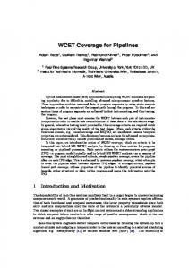
which describes the control structure of each task. A CFG is considered as a pair (N, E) where the nodes, N, represent basic blocks1 denoted by Bi and the edges from E, represent the control transfer between two basic blocks. The cache memory accesses are performed by blocks of constant size called memory blocks, or lines. A l-block is the highest number of contiguous instructions contained in a basic block and mapped to the same line in the instruction cache. A cache line may contain several l-blocks. The execution time of an instruction depends on the behavior of the instruction cache. Whether the instruction has been recently executed or is contained in the same block than its predecessor, it may be still stored in the cache, resulting in a fast access called a cache hit, or it may have been wiped out from the cache resulting in a long memory access called a cache miss. Our approach models A-way set associative caches with a LRU (Least Recently Used) replacement strategy, where a block can reside in a set of A different cache lines. A. The LRU Replacement Strategy In a LRU replacement strategy, a new block is copied into the cache in the first empty line of its set. When all the set lines are filled, the LRU strategy replaces the least recently used block. The absence or presence of a block in the cache can be determined by its relative age, where the set of ages for an A-way set associative cache is {0, 1, 2,.., A-1}. The most recently used block has age 0 and the least recently used has age A-1. We include age A to this set to represent blocks that have been loaded and then wiped out. Hence, if a block is in the cache, its age must be less than A. In the frame of the model, we use l-blocks instead of cache blocks but their behavior remain the same. We use the following algorithm to update the l-blocks ages when an lblock lb is referenced. If all cache lines of the cache set are full and lb is not in the cache, put it into the cache with age 0 and increase the age of all l-blocks in the set by 1; consequently the least recently used l-block will simply be removed from the cache set. On the other hand, if lb is already in the cache set with an age a, its age is reset to 0 and all younger l-blocks (age ≤ a) ages are incremented by 1, but ages of older l-blocks (age >a) remain unchanged. B. Cache Behaviour for the Application Our approach characterizes each task with four l-blocks sets as shown in figure 1: 1) In, the cache state before the task execution, 2) OUT, the cache state after the task execution, 3) Entry, the set of cache blocks that are first loaded in the cache when executing the task and 4) Exit, the set of cache blocks that are in the cache after the task execution. Entry and Exit are computed ignoring the inter-task cache state and assuming an empty cache or an undefined cache state at the beginning of the task. They are identical for all tasks instances in the schedule. The Entry and the Exit sets derive from the intra-task cache analysis. However, IN and OUT proceed from an inter-task cache behavior analysis. Hence Entry and Exit sets remain unchanged when the tasks execution order changes, while IN and OUT are scheduledependent sets. In the following, we explain the details of these sets computation. 1. A basic block is a maximum sequence of consecutive instructions which control flow enters at the beginning and leaves at the end without any halt or possibility of branching except at the end.
Figure 1. Task Characteristics
C. Utility of the ENTRY set We compute an ENTRY set for each task of the application because only the elements contained in this set are affected by the task chaining. It enables us to detect the hits that were considered as misses by conservative approaches. Figure 2 exhibits several behaviors of instruction cache lblocks. It displays an application tasks schedule: the execution runs from left to right. We focus on the internal CFG of the task Ti drawn horizontally. According to the given In cache state, we can compute the Out state after Ti execution whatever the actual execution of the CFG. The l-blocks having the same color are mapped to the same cache line and as we consider, in this figure, a direct-mapped instruction cache, these l-blocks conflict with each other. In State
Out State 1
a
a
b
b
c
r i
2
d
4
e
e
1. 2. 3. 4. 5. 6.
Traverse Conflicts and is in the Out State Hit and is not in the Out State Conflicts and is not in the Out State Hit and is in the Out State Is in the Out State
hh 5
2
f
c
6
r
3
i
b
e
h
g Ti-1
Ti
Figure 2 - L-blocks traversal
Ti+1
The l-blocks that are affected by the task chaining are {f, c, g, r, e, h} because they are the first encountered l-blocks in their own cache line in the CFG. r and g provides very simple cases (edge 4): they are never in the In state and consequently are always misses. Because f and c are first accessed in the CFG (2, 3), b and i are never affected by the task chaining. When Ti is running, f evicts b from the cache generating a cache miss. As opposed to c and d, b is found in the Out state because it is reloaded after f eviction and no other l-block wipes it out (2). On the other hand, c and e are always in the In state: l-block c accesses are always a hit. (3, 5) are the accesses causing the forgotten hits, they are considered as misses with a conservative empty cache state. Finally, we can notice that the line containing a is not changed (1) by the task making the task execution transparent for this line. The case of h (6) is also trivial: it fills a non-used cache line. To sum up, our intertask analysis has to detect false conservative misses (3, 5) and to propagate untouched blocks (1) in the out state that may create, in turn, hits in the following task activations. IV. IV.THE INTER-TASK ANALYSIS WITH ENTRY This method can be summarized in three steps: 1) an intratask analysis that provides, for each task, EXIT and ENTRY sets, and DAMAGE: the number of replacements that occur in the cache sets when the task finishes its execution,2) an intertask analysis that builds the IN and OUT sets for each task instance in the given scheduling, and 3) the improvement of the initial WCET estimation by combining the results of the previous steps.
195
A. The intra-task analyses To model the cache behavior, we use abstract interpretation on the cache semantics as defined in [13]. An A-way associative cache, with n lines, contains n/A cache sets and is represented by E={e0, e1, ..., e(n/A)-1}, each one consisting in A cache lines F = {l0, l1, ..., lA-1}. The CFG basic blocks, of a task Ti is a collection BB i={ B0 , B1 , ..., B m } and a basic block Bk is also a sequence of l-blocks Gen[ B k ]={ B k ,0 , ... , B k , r } . The list of l-blocks of the task Ti is a set L =∪ Gen[ B k ] , B k ∈BB i . We Ti
use LB=∪ LT to reference the list of all l-blocks of the i application. To get the index of the cache set where a l-block is mapped, the function set is used set: LB → {0, ..., (n/A)-1}. A set state, which means the set of l-blocks that are in this set at a given execution point, is a function s: E → 2LB where: ∀ l a ,l b ∈ei : ∀ lb∈ LB : lb∈ sl a ∩ sl b la = l b , we use la to denotes l-block of age a, si to refer to the state of the set ei, and S denotes all possible states of the cache sets for the given tasks list. A cache state is a function c: E ↦ S , C is the set of all possible abstract cache states. Ferdinand proposes in [3] an EXIT analysis that predicts the cache behavior using MUST and MAY analyses. We also use MUST and MAY analyses to compute the Exit set. However, we are only interested in the EXIT set at the end of the task execution. The age of a l-block Bj,k in a cache set can only be changed by references to l-blocks Br,z where set(Bj,k) = set(Br,z). The MUST analysis provides the set of l-blocks that must be in the cache after the execution of a task Ti while the MAY analysis gives the set of l-blocks that may be in the cache after the task execution. Both analyses assume an empty cache state before the task execution. We use 2 cache-set update functions that computes the new set state for a given set state and a referenced l-block, U ∩S : S ∩× L S ∩ is used for the Must analysis and T i
U ∪S : S ∪× L S ∪
for the MAY analysis. S ∩ and S ∪ contains respectively all possible Must and May states of the cache sets. These update functions operate with respect to the LRU replacement strategy in the instructions cache, that is, (1) if the block is not in the line, all line block are aged; (2) else only the block more recent than the block are aged. In any case, the accessed block get an age 0. Ti
U ∩S s ∩ ,lb = if ∃l h : lb∈ s l h [l 0 {lb } ∩ l x s l x −1 / x = 1,2 , ... ,h l h1 s∩ l h1 ∪ s∩ l h − lb l i s∩ l i / i = h2,... , A−1] ; otherwise [l 0 {lb } l x s∩ l x−1 / i = h1,... , A−1] ; ∪
U S update function is applied to the May states S ∪ and performs the same computation as U ∩S . The operator ∩ is replaced with the notation ∪ in the following equation. To compute the new cache state for a given cache state and a referenced l-block, a MUST update function U ∩C :C ∩× L C∩ , and a MAY update function T i
U ∪C :C ∪× L C∪ are used where: T i
∩
∩
∩
∩
∩
U C c ,lb = c [e set lb U S s set lb , lb] and ∪ ∪ ∪ ∪ ∪ U C c ,lb = c [e set lb U S s set lb , lb] A join function J ∩ : C ∩m C∩ combines m MUST caches states at a control flow join. The concept of this join function is like sets intersection. Hence the resulting cache state contains the l-blocks that are members of all cache states and the resulting age of a l-block is the maximum of its age in the operand states. J ∪ : C ∪m C∪ is used to combine m MAY cache states at a joint point. Its concept is like sets union. The resulting state contains the l-blocks that are members of at least one state, and the age of each l-block is equal to the minimum of its ages. The results of the EXIT analysis are not sufficient for the inter-task analysis to build the inter-task cache states. We also need to compute the number of replacements that occurred in the cache sets when the task finishes its execution, to increase the age of the l-blocks found in the set. We propose a DAMAGE analysis that provides the bounds of replacements in a particular cache set. We provide a MUST analysis that gives an upper bound for the replacements, and a MAY analysis that computes a lower bound. We define the domain of the cache-damage analysis by D ,≤ ,∪ ,∩ , where D = { 0, ... , A}⊂ℕ . The ordering relation is the order ≤ of natural numbers, and ∪{ a1, ... , a x }= max a1, ... , a x , ∩{ a 1, ... , a x }=min a1, ... , a x . We define the join operation ⊕ on elements of D, by n⊕m = A , if n m≥ A n m , otherwise We use the tuple , = , ,∪ ,∩ to represent the domain of the number of replacements, where ={ a | a : E D } , a ei is the number of replacements in a set e i , a=a ' ∀ ei ∈ E : a ei = a' e i , and aa ' ∃ei ∈E : aei ≠a' ei . The ∪ and ∩ are defined by: ∪a1, ... , a r ={∪{ a 1 ei ,... , a r e i } ,∀ e i ∈ E } ∩a1, ... , a r ={∩{ a 1 ei ,... , a r e i } ,∀ e i ∈ E } The replacement update for a given cache state and a new l-block reference is a function U D : C ×× L T , where i U D c , a , B x , y = a' is defined by: ∀ e i ∈ E :a ' e i = ae i ⊕1 ,if ∃l j ∈ F : B x , y ∈ c s il j a e i , otherwise
U ∩D : C ∩×× L is used for the MUST analysis, T i
U ∪D : C ∪×× L for the MAY analysis. T i
The EXIT and DAMAGE analyses traverse the task CFG in a descending order. Consequently, to compute them, we use the predecessors set for each basic block in the data flow analysis. As said before, the ENTRY set of each task is also computed by an intra-task analysis. As opposed to the EXIT and DAMAGE analyses, ENTRY traverses the task CFG in an ascending order starting from the CFG exit block, thus the
196
successors set is used to compute the input state of each basic block. We propose a MUST and a MAY analysis to compute the task Entry set. The Must analysis gives the set of l-blocks that must be first loaded in the cache when executing the task and the May analysis produces the set of l-blocks that may be first loaded in the cache. The same MUST and MAY update functions ( U C , U S ) ∪ ∩ and join functions( J , J ) defined for the EXIT analysis are used here but as the traversing order of the CFG is reversed, the result is the list of l-blocks that are first referenced in the cache when the task executes. Since there are only a finite number of cache sets, and a finite number of L-blocks for each task, the possible domain cache states C and cache sets states S are finite. Additionally, the update functions and the join functions are monotonic which guarantees the termination of our analyses. B. The Inter-task Analysis The purpose of this step is to analyze a static tasks scheduling to compute the cache states before and after each task execution. These sets are used to identify the hits that were considered as misses by the conservative approaches in order to tighten the estimation of the tasks WCET. The previous section has explained the details of the intra-task analyses. In this section, we are only interested in the results of the EXIT and DAMAGE analyses. To build the inter-task cache states, we apply an iterative DFA algorithm to the graph formed by the application scheduling whose nodes are the tasks instances. One may observe that this graph, formed by an unterminated loop containing a sequence of nodes, is simpler than a usual CFG. In the MUST analysis, the computed cache state holds the l-blocks that will be in the cache whatever the execution control flow of Ti. The Ti execution paths give different exit sets. These sets includes at least the MUSTEXIT set as it is the minimal exit set. Hence, to build the MUST cache state after Ti, we need to consider the upper bound of the number of replacements to age the l-blocks of the In set. In the other hand, to compute the MAY cache state, holding the l-blocks that will eventually be in the cache after Ti execution, we must use the lower bound of the number of replacements, because the May state is the union of the out cache states of all paths. The cache state update function G: C ×C× C builds a new cache state for a given cache state and a couple ∩ ∩ ∩ ∪ ∩ (cache state, Damage). We use G : C ×C × C for ∪ ∪ ∪ ∩ ∪ the MUST analysis and G : C ×C × C for the MAY analysis. These functions are defined by: OUT MUST =G∩ IN MUST , MUST EXIT , DAMAGE MUST and, ∪ OUT MAY =G IN MAY , MAY EXIT , DAMAGE MAY where : ∀ e k ∈F :OUT ∩ e k = [l i MUST EXIT e k l i ,i∈[0, j−1] and l i IN e k l i - MUST EXIT e k ,i∈[ j , A−1] j=DAMAGE MUST e k ; ] ∪
∀ e k ∈F :OUT e k = [ l i MAY EXIT e k l i ,i ∈[0, j−1] l i IN e k l i - MAY EXIT e k ∪ MAY EXIT e k l i , i∈[ j , A−1] j=DAMAGE MAY e k ;]
∩
G ages the l-blocs of the INMUST set by the highest number of replacements that occur in the cache when the current task executes, then copies in the resultant cache state the MUSTEXIT elements with their appropriate ages in ∪ MUSTEXIT. Similarly, G ages the elements of INMAY by the minimal DAMAGEMAY and then copies, in the resultant state MAYEXIT, l-blocks with their appropriate ages in MAYEXIT. C. WCET Improvement We can compute an interval of the hit count [minHit, maxHit] for each task instance in the application scheduling. While minHit is provided by combining the results of the inter-task MUST analysis and MUST ENTRY analysis, maxHit combines the results of the inter-task MAY analysis and MAY ENTRY analysis as shown in figure 3 . minHit =cardinal IN MUST ∩MUST ENTRY maxHit =cardinal IN MAY ∩ MAY ENTRY Figure 3 - Hit count bounds
minHit is the asserted result that we obtain whatever the execution path is while maxHit is an upper bound. If the execution path is known, the hit number will be at least greater or equal to minHit and less than or equal to maxHit. Having the hit number (nbHit), the hit cost and miss penalty, the new estimation of the task WCET is given by: WCET New = WCET Old −nbHit ×miss penality nbHit× Hit Cost (1) We only use the MUST analysis results in our experimentations, so nbHit is replaced by minHit. While the results of the MUST analysis are pessimistic, they are conservative. We show in our experimentations that in spite of being conservative, the results are significant. V. ENTRY EXPERIMENTAL RESULTS We have experimented our approach on PapaBench [10] and the results are exposed here. A. Benchmarks We used PapaBench2 [17], a benchmark issued from a real application (UAV control) to get objective results. PapaBench2 is quite similar to PapaBench except that tasks T9, T10 et T13 are split into a set of smaller tasks to improve the scheduling flexibility. We used the automatic mode as it exhibits the most critical part. The scheduling of the tasks running on processor MCU1 can be analyzed independently of those running on MCU0. As we suppose that interrupts are periodic, they are considered as tasks. Finally, the program running on MCU1 counts 8 tasks and on MCU0 31 tasks. B. Tools Our cache static analysis has been performed in the OTAWA [8, 9] framework. In this tool, the WCET computation is viewed as performing a chain of analyses that use and produce annotations hooked to the code until getting the WCET evaluation. We choose the Implicit Path Evaluation Technique [1] in our experiments to compute the WCET and the adaptation of the Ferdinand's categorization approach [3], CAT2, to IPET to estimate the effects of the instruction cache on execution time. The static schedules of each processor tasks used in our experiments have been generated by CHEDDAR [11], a
197
100% 90% 80% 70% 60% 50%
I1 I2 I4 I5 I6 T3 T4 T5 T7 T8 T9 T10 T 11 T12 T13 T14 T15 T 16 T17 T18 T19 T20 T 21 T22 T23 T 24 T 25 T26 T27 I1 I2 I4 I5 I6 T3 T4 T5 T7 T8 T9 T10 T11 T12 T13 T14 T 15 T16 T17 T 18 T19 T20 T21 T22 T 23 T24 T25 T26 T27 I1 I2 I4 I5 I6 T3 T4 T5 T7 T8 T9 T10 T11 T12 T 13 T14 T15 T 16 T17 T 18 T19 T20 T21 T 22 T23 T24 T25 T26 T 27
40%
A1
A2
A ve ra g e W C E T
A4
G a in R a tio
Figure 4 - WCET Improvement
8 B y te s 1 6 B y te s 3 2 B y te s
12 10 8 6 4 2
20000
0 0 0 0 0 0 0
8KB
15000 10000 5000 A1
A2 M CU1
A4
0 A1
A2
A4
M C U0
100
16KB
95
32KB
90
64KB
85
128KB
25000
105
20000 15000 10000
80
5000
75 A1
A2 M CU1
Figure 5 - Hit Count (fixed cache size 64KB)
resource requirements analyzer which provides analytical and simulation performance analysis methods / tools. It focuses on tasks, processors, shared resources, buffers and task dependencies. To perform the experimentations, we have tested different instruction cache configurations with the same processor pipeline. As our IPET approach uses processor simulation to compute the times of program parts, we have chosen a generic four stages in-order pipeline with execution in-order. All stages process two instructions by cycle with two ALU and two float computation functional units. The used binary programs were compiled for a PowerPC ISA. The program running on MCU1 processor has a code size of 320 KB while the program on MCU0 is a bit bigger with 370 KB. C. Results We analyze different configurations of A-way associative instruction caches to evaluate their impact on the WCET estimation with our method. The cache size, the block size and the associativity degree A are taken into consideration. We have considered Rate Monotonic scheduling for MCU0 and MCU1 tasks in our computations but any other static nonscheduling policy may be used. First, we have fixed the cache size to 64 KB and tested different block sizes: 8, 16 and 32 bytes. The impact of the block size variation is tested for three degrees of associativity: 1, 2 and 4. The results are shown for the two programs in figure 5. Vertically, we measure the total number of forgotten cache hits for a cycle of the RM scheduling, that is, the number of l-block causing hits whatever the tasks execution paths, which is the result of the MUST analysis. The count of hits per block size, is significant for all associativity degrees and enforces the interest in our approach. Little cache block sizes exhibit best inter-task analysis results. Small cache basic blocks benefit from the random distribution of code in memory and create less cache block aliasing effects on cache wiping between tasks. Finally, the hit count of MCU1 is much smaller than MCU0 for the considered cache configuration because the tasks of MCU1 are very much smaller than the tasks of MCU0.
A4
A1
A2
A4
M CU0
Figure 6 - Hit Count (fixed block size 8 bytes)
In the second set of measures, we have fixed the cache block size to 8 bytes and we have performed our analysis for different cache sizes: 8KB, 16KB, 32KB, 64KB and 128KB, having different associativity degrees: 1, 2 and 4. Figure 6 uses the same notation as figure 5. Notice that, in all cases, the cache is much smaller than the code size of MCU0 and MCU1 inducing a realistic load on the cache use. While the cache size should improve the WCET of the tasks, it seems to have very few effects on the inter-task analysis of MCU1. However for MCU0, the hit count increases with the cache size for A1, A2 and A4. Theses results enables us to choose the appropriate cache size. While the biggest cache size, 128KB, generates the best results we can choose a smaller size for mcu1, 32KB, or even 16KB. We can also deduce from figures 5 and 6, that increasing the associativity degree is not always needed to boost the hits count. For MCU1, we can settle for a 2-way associative cache as it gives the same results as a 4-way associative cache. Lastly, we have computed the tasks WCET for all instruction cache configurations used in the previous experimentations with the processor described in the previous section, a miss penalty of 10 cycles, and a hit cost of 1 cycle. Then we have improved the WCET with the results of the hit count of our inter-task analysis by simply subtracting 9 cycles by each forgotten hit, counted as a miss by the conservative WCET analysis. Indeed, the CAT method just counts the number of misses and add the resulting penalty in cycles to the WCET. Figure 4 shows the results of our computation. Horizontally, we have the list of tasks of MCU0 and MCU1 while the vertical bars represent 100% of the WCET of each task. The gray part of each bar represents the number of penalty cycles subtracted to the conservative WCET and, consequently, the black part represents the WCET after fix. This figure shows that our approach can tighten the WCET estimate at least by 9,2% over approaches that does not consider the inter-task cache analysis. It also shows that the enhancement can reach 51% for some tasks. In fact, these
198
100% 90% 80% 70% 60% 50% 40%
In je c t io n
T27
T26
T25
T24
T23
T22
T21
T20
T19
T18
T17
T16
T15
T14
T13
T12
T11
T9
T10
T8
T7
T5
T4
I6
T3
I5
I4
I2
I1
T27
T26
T25
T24
T23
T22
T21
T20
T19
T18
T17
T16
T15
T14
T13
T12
T11
T9
T10
T8
T7
T5
T4
I6
T3
I5
I4
I2
I1
30%
E N TR Y A ve ra g e W C E T
G a in ra t io
Figure 7 - Injection vice ENTRY, cache (16KB, 8 Bytes, 2) 3 0 0
2 1 0 0 0
2 5 0
2 0 0 0 0
2 0 0
1 9 0 0 0
1 5 0
In j e c t i o n
1 8 0 0 0
1 0 0
E N TR Y
1 7 0 0 0
5 0
1 6 0 0 0
0 A 1
A 2 In je c t io n
A 4
A 8
1 5 0 0 0 A 1
A 2
A 4
A 8
E N T R Y
Figure 8 - MCU1, Injection vice Entry
tasks are often repeated having a big frequency (T7) and/or have a very small size compared to the remaining tasks (I1). In this experiment, we have only used the results of the MUST analysis as it is the improvement that we provide and it does not depend on the task flow execution. On the opposite, the MAY analysis provides an upper bound of the inter-task hits but it depends on the flow execution. Yet, this kind of information should be useful to provide a non-empty conservative state to intra-task instruction cache WCET analyses. VI. INTER-TASK CACHE STATES INJECTION PRINCIPLE In the previous section, we show that the MUSTENTRY analysis can tighten the WCET estimation by 9% over approaches that do not consider the inter-task cache analysis. It also shows that the enhancement can reach 51% for some tasks. However, the MUSTENTRY approach gives results that are common to all possible execution paths and not only the worst execution path. Now if we consider the worst execution path alone, we can compute an ENTRY set that is at least equal to the MUST ENTRY set. This leads to some pessimism in the new computation of the WCET with equation (1) because the exact number of hits of the worst case execution path is at least equal to the number of hits provided by the MUSTENTRY set.
Figure 9: Example of a task's CFG
As an example, figure 9 shows a task CFG consisting of four basic blocks having one l-block each. We consider a direct mapped instruction cache of four lines. The l-blocks having the same color are mapped to the same cache line. The IN cache state build by the inter-task analysis is shown on the left. The CFG has two possible execution paths. The MUST analysis gives a MUSTEntry set holding the two l-blocks {1, 2}
Figure 10 - MCU0, Injection vice Entry
as they are common to the two possible paths. The IN state contains 1 and 2. So, if we consider a miss penalty equal to 10 and a hit cost equal to 1 clock cycle(s), equation (1) reduces the old WCET estimation by 18 cycles. This new estimation is denoted by w1. However this analysis does not consider the worst execution path alone. Suppose that the worst execution path is (1, 2, 4, 5), if we replace the conservative assumption “an empty IN state” by the real IN state, the WCET computation will identify three hits instead of two because l-blocks 1, 2 and 4 are already in the cache. So, the new WCET estimation w2 becomes smaller than w1. This is the major advantage of the “Injection”, because the WCET computation with a non empty cache state gives an estimation that is at most equal to the estimation provided by the Entry analysis. For example, if the IN state does not contain the l-block 4, w2 will be equal to w1. We have discussed the advantage of the Injection and the ENTRY analyses in the previous sections. Now we compare the results of both methods on a RM scheduling of MCU0 and MCU1 tasks, with an instruction cache of 16KB and 8 bytes for the block size. We show the impact of these methods for different associativity degrees of the same cache configuration. Figures 8 and 10 show the results for MCU1 and MCU0 respectively. Vertically, we measure the total number of forgotten cache hits for a cycle of the RM scheduling using the MUST analysis. For each associativity degree, the left column show the results of the Injection and the right one displays the ENTRY results. We can notice that with this cache configuration and the RM scheduling the difference between Injection and ENTRY is very large for both processors scheduling. Using a non empty cache state to replace the conservative assumptions in the WCET computation is very useful to reduce the WCET estimation but this process is much computation time expensive than the ENTRY analysis. So when the difference is not large enough the ENTRY analysis is sufficient. However, Injection is recommended when the difference is very large as in the case of MCU1 and MCU0, because it gives a tighten estimation of the tasks WCET. Finally, we compare in figure 7 the results of Injection and ENTRY, for an RM scheduling of MCU0 and MCU1, with a 2-way instruction cache of 16KB and8 bytes for the block size. Horizontally, we have the list of tasks of MCU0 and
199
MCU1 while the vertical bars represent 100% of the WCET of each task. The gray part of each bar represents the number of penalty cycles subtracted to the conservative WCET and, consequently, the black part represents the WCET after fix. The results shows that Injection can tighten the WCET by 9,7% and reaches a maximum of 64% while ENTRY tighten the estimation of 7% and reaches 55%. VI. VI.CONCLUSION We have presented an analysis of an A-way associative instruction cache behavior combining inter- and intra-task instruction cache analysis to estimate the number of cache hits due to task chaining. A MAY and a MUST analysis are provided to compute the cache states between tasks. As the MUST analysis gives the lower and safe bound of the hit count due to task chaining, we have presented its results considering that the MAY analysis is mostly useful to tighten the WCET intra-task estimation. Although we consider the MUST bound, the WCET estimate is tightened by an average of 9,2% over approaches that do not consider the inter-task cache analysis. Our approach can be viewed as a lens filtering the cache hits due to task chaining to reduce the WCET estimation deduced from any WCET computation methods bound to intra-task cache analysis . On another hand, we have provided a second use for the inter-task cache states to tighten the WCET estimation: the injection process. It consists in using the inter-task cache states with the single-task approach, that provided the initial WCET estimations, to compute the tasks new WCETs. We have only exploited the MUST analysis, this would allow to benefit from the MAY analysis results too. Then, in our experimentation, we have considered a static task schedule that is not changed by the reduction of the WCET of the tasks. We want to examine the impact of the WCET reduction on the schedule and the back effect of the new schedule on the intertask analysis results. We hope to find a strategy to converge towards a static schedule with a minimal overall WCET of the application. Moreover, it will be also interesting to experiment our analyses on dynamic scheduling policies. As a last word , we believe that it should be interesting to adapt our approach to hardware devices with long-term effects whose behavior depends on the task schedule such as branch prediction and data caches.
REFERENCES 1]
2]
3]
4] 5]
6]
7]
8]
9]
10] 11]
12]
13]
14]
15]
16]
17]
Y.-T. S. Li, S. Malik. “Efficient Microarchitecture Modeling and Path Analysis for Real-Time Software”. 16th IEEE Real-Time Systems Symposium, pp. 298-307, 1995. Y.-T. S. Li, S. Malik. “Cache Modeling for Real-Time Software:Beyond Direct Mapped Instruction Caches”. 17th IEEE Real-Time Systems Symposium, 1996. C. Ferdinand et al. “Applying Compiler Techniques to Cache Behavior Prediction”. ACM SIGPLAN Workshop on Languages, Compilers, and Tools Support for Real-Time Systems, pp. 37– 46, June 1997. F. Mueller. “Timing analysis for instruction caches”. Real-Time Systems, 18(2/3):209–239, May 2000. Y. Tan, V. Mooney. “ Integrated Intra- and Inter-Task Cache Analysis for Preemptive Multi-Tasking Real-Time Systems”. 8th International Workshop, SCOPES, in Lecture Notes on Computer Science, LNCS3199, pp. 182–199, 2004. Y. Tan, V. Mooney. “ Timing Analysis for Preemptive Multi-Tasking RealTime Systems with caches”. Design, Automation and Test in Europe Conference and Exhibition, Vol 2, pp. 1034 – 1039, 2004. I.Wenzel, B.Rieder, R. Kirner, P. Puschner. “Automatic Timing Model Generation by CFG Partitioning and Model Checking”. Design, Automation and Test in Europe, Vol. 1, pp. 606-611, 2005. H. Cassé, C. Rochange, P. Sainrat. “An open Framework for WCET Analysis”. IEEE Real-Time Systems Symposium-WIP session, pp. 13-16, 2004. H. Cassé, C. Rochange, P. Sainrat. “OTAWA, a framework for experimenting WCET computations”. 3rd European Congress on Embedded Real-Time, 2005. F. Nemer, H. Cassé, P. Sainrat, J.P. Bahsoun, M. De Michiel. PapaBench: a free real-time benchmark. 6th WCET Workshop, 2006. F. Singhoff, J. Legrand, L. Nana. AADL resource requirement analysis with CHEDDAR. SAE AADL Working Group meeting, Paris, October 19-21, 2005. P. Feiler, D. P. Glush, J. J. Hudak, B. A. Lewis. “Embedded System Architecture Analysis Using SAE AADL”, Technical note CMU/SEI2004-TN-005, Carnegie Mellon University, 2004. A. Rakib, O. Parshin, S. Thesing, R. Wilhelm. Component-Wise Instruction-Cache Behavior Prediction. pp. 211-229, vol. 3299, Lecture Notes in Computer Science, 2004. I. Puaut and D. Decotigny. Low-complexity algorithms for static cache locking in multitasking hard real-time systems. 23rd IEEE Real-Time Systems Symposium (RTSS02), 2002. J. Staschulat, R. Ernst. Cache Effects in Multi Process Real-Time Systems with Preemptive Scheduling. Technical report, IDA, TU Braunschweig, Germany, November 2003. F. Nemer, H. Cassé, P. Sainrat, A. Awada. “Improving the WCET accuracy by inter-task instruction cache analysis”. IEEE International Symposium on Industrial Embedded Systems SIES, Lisbon, July 2007, pp. 25-32. PapaBench2, http://www.irit.fr/TRACES.
200