Aug 2, 2010 - Ilkwon Park1, Manbae Kim2, Seungwon Lee1, Young Han Lee3, ... Hong Kook Kim3, Jin-Woo Bae4, Ji-Sang Yoo4, and Hyeran Byun1.
INTERACTIVE MULTI-VIEW VIDEO AND VIEW-DEPENDENT AUDIO UNDER MPEG-21 DIA (DIGITAL ITEM ADAPTATION) Ilkwon Park1, Manbae Kim2, Seungwon Lee1, Young Han Lee3, Jun-Sup Kwon2, Won-Young Hwang2, Hong Kook Kim3, Jin-Woo Bae4, Ji-Sang Yoo4, and Hyeran Byun1 1
2
Dept. of Computer Science, Yonsei University Department of Computer, Information, and Telecommunication, Kangwon National University 3 Dept. of Information and Communications, Gwangju Institute of Science and Technology 4 Department of Electronic Engineering, Kwangwoon University Republic of Korea ABSTRACT
In this paper, we propose an efficient multi-view system that transmits two view sequences for stereoscopic display and audio according to user’s request. The process for users’ preferences is integrated into MPEG-21 DIA. MultiViewAdaptation descriptors defined in DIA is used to deliver users’ preferences and device capabilities. Furthermore, we newly introduce multi-view descriptions that are represented in XML (eXtensible Markup Language) schema. Our proposed system also provides view-dependent audio according to user preferences. When a user changes a view from the center of the multi-view video to either the left or the right, audio signals are rendered to have directional information of viewer’s movement prior to being played out. Integrating audio with multi-view delivers more realistic perceptions. Index Terms—Interactive multi-view video system, View-dependent 3D audio, MPEG-21 DIA
In this paper, we propose a multi-view system that is designed to provide multi-view video as well as 3D audio together. The support of 3D audio can enhance the functionality of multi-view system. This clearly differentiates our system from other existing ones that only put efforts on how to present a variety of multi-view video types. As well, we will present how to smooth the excessive 3D variation as well as to make intermediate images. 2. ARCHITECTURE BASED ON MPEG-21 DIA 2.1. Multi-view DIA description A Digital Item (DI) is the basic unit of transaction in the MPEG-21 framework. MPEG-21 DIA specifies the syntax and semantics of tools that may be used to assist the adaptation of Digital Items [5, 6]. Table 1. The semantics of MultiViewAdaptation DS Name DisplayDevice
1. INTRODUCTION Recently, multi-view media services are becoming more and more feasible in practices and are expected to be one of the next generation’s multimedia services because it is able to offer more realistic scenes by “continuous look-around” from different viewpoints. Despite previous works on multiview video [1-4], an integration work combining audio and video is relatively few. The multi-view data which are made up of multiple camera sequences and multi-channel audio stream requires enormous amount of storage. Instead of sending entire multi-view data, we select and transmit a part of views and audio sequences according to users’ preferences that are operated in MPEG-21 DIA [5]. Therefore, our system is compatible with the international standard MPEG-21 multimedia framework. Unlike rendering 2D video, stereoscopic video processing needs to be carefully designed to avoid any 3D visual discomfort. For instance, while changing the viewpoints, the excessive variation of 3D perception occurs.
ViewNumber
3DDepthRange MonitorDisparity ViewSweeping FreezeFrame
Definition Describes if the display is a monoscopic, stereoscopic, or multi-view display Describes the camera number which is chosen by the user among multiple cameras. Describes the range of 3D perceived by user. The range is the distance between monitor screen and objects in 3D. Its value is varied at [0.0. 1.0], where 0.0 and 1.0 indicates the lowest and highest of the depth, respectively. Describes the stereoscopic disparity of 3D monitor Describes if user wants view sweeping or not Describes if user wants to see freezed frames or not
For the effective communications between the server and client, we present a description scheme (DS) for multiview video, which is primarily related to Display Presentation Preferences and Terminal Capabilities that are currently defined by DIA description tool. We propose multi-view related issues as well as the previous standard descriptions. The semantics of the proposed MultiViewAdaptation DS is explained in Table. 1. 2.2. System Implementation
Authorized licensed use limited to: Yonsei University. Downloaded on August 02,2010 at 08:54:08 UTC from IEEE Xplore. Restrictions apply.
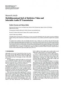
Fig. 1 shows the proposed architecture of the multi-view video and view-dependent audio system. The DIA server is composed of a resource adaptation engine and a description adaptation engine. The description adaptation engine receives and parses the user preference description XML file. The resource adaptation engine adapts resources according to user preferences contained in the description.
Fig. 1. The architecture of multi-view video and view-dependent audio
The server is composed of five main modules: Description Adaptation Engine, View Selection, Computation of L, Intermediate View Reconstruction (IVR), 3D Depth Adaptation, Video Generation, and ViewDependent Audio Reconstruction (VAR). L is the number of intermediate frames between two neighboring camera views. The description adaptation engine parses the userpreference XML file. View selection generates two camera views. In the Computation of L, the number of intermediate views is computed based upon 3D monitor property and camera setup information. Then, IVR produces the intermediate views according to L. The stereoscopic depth range is controlled by 3D Depth Adaptation. Finally, the VAR makes the user at the client hear different audio according to a view preference. At the client side, there are two main modules; the Digital Item Player (DIP) and User Preference Generator. The DIP plays and renders DIs. The user preference generator generates user preference descriptions contained in XML files, and transmits them to the server. 3. INTERACTIVE MULTI-VIEW VIDEO 3.1. View Selection One of key features of a multi-view transmission system is the selection of viewpoints according to user preference. A descriptor used for a viewpoint selection is ViewNumber that is delivered from the client to DIA description adaptation engine in the server. The adaptation engine then parses this description to analyze the user’s request. The DIA server halts sending a current view video and starts sending the view which was selected by the information from the parsed description.
In rendering views, two important aspects need to be taken into account. The first one is the necessity of intermediate frames. Since the baseline between two neighboring cameras is generally larger than 20 ㎝ in multi-view camera configuration, the stereoscopic image causes a visual discomfort due to large disparity between the left and right images. Therefore, the number of intermediate frames should be correctly estimated before intermediate view reconstruction. The other problem happens while changing views. Even if intermediate views are made and rendered on a 3D monitor, view switching still causes a large disparity between the current and next views. Therefore, for smooth transition, a stereoscopic view sweeping scheme is employed. 3.3. Computing the number of intermediate images In general, a 3D monitor is composed of two-view or multiview. Regardless of the number of views, each monitor has its own disparity between left and right images for stable stereoscopic viewing. For multi-view monitors, disparity is the distance between leftmost and rightmost images on the screen. Views with accurate disparity should be rendered to 3D display in order to produce smooth 3D perception of viewers. Therefore, at the server side, sending two images satisfying such requirement to the client is an important task. Such requirement is related to the decision of the number of intermediate views, L. Given multi-view cameras and a 3D M-view monitor, L is defined by M •B (1) L≥ −1 D
where B is the baseline between two neighboring cameras and D is the disparity of an M-view monitor. 3.4. Intermediate View Reconstruction Intermediate views are generated by the method proposed in [2]. To generate a depth image, a reference depth image is generated by a correlation between images acquired from left and right cameras in the middle of given multi-view cameras [7]. The description of MonitorDisparity is sent to a DIA sever by a client and the server generates intermediate images according to the descriptor. 3.6. 3D Depth Adaptation The display of stereoscopic video requires a pair of left and right images. In this procedure, it is possible to control 3D depth according to the selection of the pair. Given two camera images, Fi and Fi+1 and their intermediate frames, B1, B2, ..., BL, we can select any pair of frames by setting a frame interval, η that is described by 3DDepthRange. In Fig. 2, (a) and (b) shows two cases with η = 1, 3, respectively. In (a), F1 and B1 are chosen, and F1 and B3 are used in (b). It is apparent that (b) produces larger 3D depth perception than (a).
3.2. Aspects of Rendering Views
Authorized licensed use limited to: Yonsei University. Downloaded on August 02,2010 at 08:54:08 UTC from IEEE Xplore. Restrictions apply.
Fig. 2. The selection of two frames as varying value of 3DDepthRange.
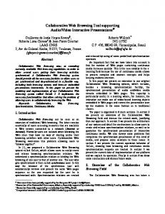
4. VIEW DEPENDENT AUDIO RECONSTRUCTION Fig. 3 shows an overview of the proposed view-dependent audio reconstruction (VAR) employed in the multi-view system. Here, audio data applied to VAR are assumed to be recorded by the multi-channel microphones, typically 5.1 channel microphones, and are going to be played out to the multi-channel loudspeakers speaker located at the center of the multi-view system. When the user preference is changed, i.e., the user moves from the center of the multi-view system to either the left or the right, audio signals should be rendered to have directional information of user’s movement according to the user preference prior to being played out.
In order to describe the procedure of VAR, we first define m and n as the channel number of the input audio and the rendered output audio, respectively. Initially, each input audio channel is directly mapped to its corresponding output audio channel. In other words, the n-th output audio channel is identical to the n-th input audio channel such as Outputn = Inputn for n = 1(L), 2(C), 3(R), 4(RS), and 5(LS), where the low frequency enhancement (LFE) channel is not rendered because the LFE speaker can be located at any place. The procedure of reconstructing view-dependent audio signals is as follows: 1. For a given user preference, we first calculate φ that is the angle deviated from the center speaker of the original configuration to that of the desired configuration. 2. As a first step of channel panning, we obtain a pair of speakers which cover the panned angle defined by Panned n = Input n + φ for the n-th input audio channel. By using the panned angle of the n-th input audio channel, the m-th and (m+1)-th speakers are selected if (2) θ m ≤ Panned n ≤ θ m+1 where m+1 is set to 1 if m = 5. 3. In order to generate the output audio signals when the panned angle, Panned n , is not identical to any speaker angle, we obtain a weighting factor, α m, n = 1 −
Fig. 3. Overview of the proposed view-dependent audio reconstruction according to the user preference based on channel panning.
A configuration of the multi-channel loudspeakers used in the multi-view system is shown in Fig. 4, which is defined by the ITU-R Recommendation BS.1116 [8]. The angles from the user to the center speaker, the left speaker, the right speaker, the left surround speaker, and the right surround speaker are set to 0°, +30°, -30°, +110°, and -110°, respectively, and the radius is approximately 2 to 3 meters.
α m,n , defined as
Pannedn − θ m
(3)
θ m,m+1
where Pannedn and θ m are the panned angle and the selected speaker angle from Eq. (2). θ m , m +1 is the angle between the m-th and (m+1)-th speaker, which is shown in Fig. 5. α m,n ( 0 ≤ α m ,n ≤ 1 ) can be interpreted as the contribution of the n-th input audio to the m-th output audio. In addition, the weighting factor of the n-th input audio to the (m+1)-th output audio is computed as (4) α m+1,n = 1 − α m,n . 4. The output audio signals are finally reconstructed by the weighted sum of all the input audio channels as . (5) Output m =
5
∑ (α n =1
m ,n
⋅ Input n )
5. EXPERIMENTAL RESULTS
Fig. 4. Configuration of multi-channel loudspeakers used in the multi-view system
In this section, we present the performance of our proposed methods that are IVR, translational view sweeping, and VAR are discussed. Fig. 5 shows the results of stereoscopic view sweeping by using IVR. Furthermore, F1 and F2 are the neighboring real camera views. B1 and B2 are sequential intermediate views. Fig. 6 shows a camera view, an intermediate view and their stereoscopic images. Stereoscopic image is generated by interlacing a camera image and an intermediate image that is generated from view 1 and view 2.
Authorized licensed use limited to: Yonsei University. Downloaded on August 02,2010 at 08:54:08 UTC from IEEE Xplore. Restrictions apply.
another based on the weighting factor computed from Eqs. (3) and (4). Next, we performed an experiment by using an actual audio sound and it was found out that the channel panning was successfully achieved. View 4
View 5
B1
B1
B2
B2
Fig. 5 Stereoscopic view sweeping.
Fig. 6. Camera image, intermediate image, and stereoscopic image.
6. CONCLUSION In this paper, we presented a system being composed of multi-view video and view-dependent 3D audio under MPEG-21 DIA environments. Following MultiViewAdaptation DS proposed in this paper, we validated the feasibility of the descriptions through experiments. DIA descriptions depict stereoscopic view selection from multiview and accordingly the view-dependent audio. For smooth stereoscopic display during view changes, a translational view sweeping was presented. As well, the calculation method of the number of intermediate images was presented based on 3D monitor and camera information. ACKNOWLEDGEMNT This research was supported by the MIC, Korea, under the ITRC support program (GIST-RBRC) supervised by the IITA . (IITA-2006-C1090-0603-0017) 7. REFERENCES
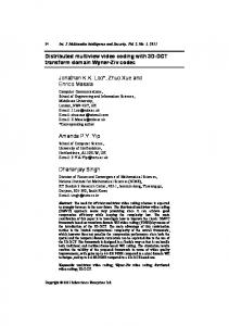
Fig. 7. Performance of the proposed view-dependent audio reconstruction. The normalized magnitude of each output channel is displayed according to the user’s view selection.
In order to evaluate the performance of the proposed viewdependent audio reconstruction described in Section 4, we measured the magnitude of each output channel when a tone signal was used as a test audio signal. When the user was located at the front of the center speaker, the user heard the tone signal only from the center speaker. However, the user could start to hear the tone signal from other speakers as the user moved. Fig. 7 shows the normalized magnitude of the tone signal measured at each output channel according to the user preference, where x-axis presents the angle according to the user’s view selection and y-axis presents the normalized magnitude. As can be seen from the figure, the audio signals were played out from the center speaker and the right speaker when the user moved from 0° to 30°. By moving from 30° to 60°, the center speaker played nothing while the right surround speaker started to play out because the panned angle was located between the right and the right surround speakers. Of course, the strength of the tone signal was linearly changed from one speaker to
[1] A. Vetro, W. Matusik, H. Pfister, and J. Xin, “Coding approaches for end-to-end 3D TV systems,” Proceedings of Picture Coding Symposium, Dec. 2005. [2] C. L. Zitnick, S. B. Kang, M. Uyttendaele, S. A. J. Winder, and R. Szeliski, “High-quality video view interpolation using a layered representation,” ACM SIGGRAPH and ACM Trans. on Graphics, vol. 23, no. 3, pp. 600-608, Aug. 2004. [3] Z. Yang. B. Yu, K. Nahrstdet, and R. Bajscy, “A multi-stream adaptation framework for bandwidth management in 3D teleimmersion,” Proceedings of Network and Operating System Support for Digital Audio and Video (NOSSDAV), pp. 80-85, May 2006. [4] J. G. Lou, H. Cai, and K. Li, “A real-time interactive multiview video system,” Proceedings of the 13th Annual ACM International Conference on Multimedia (Multimedia ‘05), pp. 161-170, Nov. 2005. [5] “MPEG-21 Overview V.4,” ISO/IEC/JTC1/SC29/WG11 N4801, May 2002. [6] M. Kim, J. Nam, W. Baek, J. Son, and J. Hong, “The adaptation of 3D stereoscopic video in MPEG-21 DIA,” Signal Processing: Image Communication, vol. 18, no. 8, pp. 685-697, Sept. 2003. [7] D. Scharstein and R. Szeliski, “A taxonomy and evaluation of dense two-frame stereo correspondence algorithms,” International Journal of Computer Vision, vol. 47, no. 1, pp. 7-42, April-June 2002. [8] ITU-R Recommendation BS.1116, Methods for the subjective assessment of small impairments in audio systems including multichannel sound systems, Oct. 1997.
Authorized licensed use limited to: Yonsei University. Downloaded on August 02,2010 at 08:54:08 UTC from IEEE Xplore. Restrictions apply.