The current issue and full text archive of this journal is available at www.emeraldinsight.com/0969-9988.htm
ECAM 13,3
Internet-based database management system for project control
242
Ji Li US Noah Technology Corp., Monterey Park, California, USA, and
Osama Moselhi and Sabah Alkass Department of Building, Civil & Environmental Engineering, Concordia University, Montreal, Canada Abstract Purpose – The objective of this paper is to develop an efficient project management system to track and control construction activities for contractors and/or project managers. Design/methodology/approach – The work package model is utilized to break down project data into activities and work tasks. The data structure of a project is represented using the entities-relationship methodology. A relational database stores all of the project data. The earned value method calculates the cost and schedule variances. The internet-based platform with three-tier client-server architecture is chosen for system implementation. Findings – The developed project database stores all of the project data necessary to perform project control functions. The implementation of the project database management system is efficient. The developed system provides real-time data sharing and a collaborating environment in support of project control. Originality/value – Time and cost control are essential management functions for achieving successful delivery of engineering, procurement and construction (EPC) projects. The developed system can assist contractors and/or project managers in tracking and control of their construction projects in a real-time manner. Keywords Database management systems, Internet, Project management, Construction industry Paper type Research paper
Engineering, Construction and Architectural Management Vol. 13 No. 3, 2006 pp. 242-253 q Emerald Group Publishing Limited 0969-9988 DOI 10.1108/09699980610669679
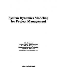
Introduction Database management systems (DBMSs) are essential in supporting project tracking and control functions. A database provides a platform to organize, store and retrieve the planned and actual performance data of projects in a logical and efficient manner. The DBMS queries the stored project data using SQL (structured query language) to generate different management reports for control purposes. It follows that the design of the database should follow a well-defined structure to support the tracking and control of individual tasks at different levels of reporting. The data structure should also facilitate the linkage of those individual tasks to their respective construction trades. A work package model is commonly used to describe the data structure of a project. The work package is a general expression that represents a well-defined scope of work that usually terminates in a deliverable product. It includes activities and tasks within those activities as depicted in the work breakdown structure (WBS) shown in Figure 1. The WBS is generally configured in accordance with the way the work will be
Internet system for project control 243
Figure 1. WBS and Control-object
performed and reflects the way in which project costs and data will be summarized and eventually reported (Kerzner, 1995). The application of DBMSs for project control has been explored by a number of researchers. Abudayyeh (1991; Abudayyeh and Rasdorf, 1993) developed a DBMS to support automated cost and schedule control functions. He used the work package model to represent the project data. His system, however, only supports the application of earned value for progress reporting. The earned-value method (Canadian General Standards Board, 1999, Department of Defense, 1967) integrates time and cost to overcome the limitations of traditional control methods, which use the cost as the only indicator for the performance of a task. The method is widely accepted as an integrated project control tool (Fleming and Koppelmam, 2000). However, this method only tracks cost and schedule variances, and neither supports reasoning to explain unacceptable performance nor advises on possible corrective action(s). To overcome those limitations, DBMSs have been used in conjunction with knowledge-based expert systems for project control. Diekmann and Al-Tabtabai (1992) presented a knowledge-based approach for project control. In their system, a single form is used to store data pertinent to individual work packages. Their control functions focus on individual work packages. Fayek et al. (1998) proposed a prototype rule-based expert system to improve project control. Two forms of data – one related to activities, the other related to the project – are defined to map the data structure of a project. The developed system can be implemented at project and activity levels. Moselhi et al. (2001, 2002, 2004) proposed a web-based system for project control of control objects. An object-based model is proposed to integrate the project data in support of project control functions. The developed system can be implemented at project, control-object, and resource levels. However, none of these systems are web-based, except those proposed by Moselhi et al. (2001, 2002, 2004). They neither support performance control of a project on remote sites nor provide the ability to share information. This paper presents an internet-based database management system designed to support contractors and/or project managers in tracking a project’s progress. The paper focuses primarily on the system database, which provides a high degree of flexibility
ECAM 13,3
244
through its data structure to support three-level project control. The paper also presents a numerical example to demonstrate the use of the developed system and to illustrate its essential features.
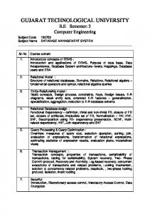
Overview of the developed system The developed system consists of seven main components: (1) user interfaces; (2) input/edit; (3) evaluation; (4) reasoning; (5) forecasting; (6) reporting; and (7) databases. The system is shown in Figure 2. The user interface provides a viewing/input window that allows users to interact with the system through the worldwide web using an internet browser; the input/edit is a data input, update and delete component that is developed to facilitate data entry and edit; the evaluation component assesses the cost and schedule variances using the earned-value method (Canadian General Standards Board, 1999; Department of Defense, 1967); the reasoning component diagnoses possible reasons behind the variances through a set of built-in indicators; the forecasting component predicts the project’s time and cost at completion; the reporting component generates the performance reports on a daily, weekly, monthly, and/or yearly basis. The reports have a tabular format as well as a graphic format that can be generated in a user-friendly manner. Two relational databases (project and historical) are developed. The project database stores planned and actual cost and schedule data for the project being considered. Upon completion of the project, all information collected in the project database is transferred to the historical database. The historical database has the same structure as the project database.
Figure 2. System layout
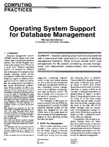
Developed database Data structure is essential to the development of an efficient database. This is particularly important in supporting project control functions. Project control is carried out using a set of control objects as proposed by Moselhi et al. (2001, 2002). The control object, which is shown in Figure 1, could represent a phase of a project, a work package, and/or a cost account defined using cost breakdown structure (CBS). It has the resources necessary to complete the tasks included within that control object. Based on this, all of the project data can be treated as an aggregation of a pre-defined set of control objects. Each control object has its resources of labor, material, equipment, and sub-contractors. In the proposed system, sub-contractors are treated as a type of resource. Each resource has a budgeted value and an actual consumed value. Each control object has relation(s) to other control objects as well as its own method of resource allocation. It also has attributes that describe its characteristics, such as sensitivity to weather and site congestion, as well as a set of threshold values that defines unacceptable performance. Each type of resource in a control object may have single or multiple sub-resources. It should be noted that each control object is an abstract representation of a physical component of a project, as stated earlier. The budgeted resources of a control object serve as a control reference as they are actually consumed over the project duration. Representation of project data The entities-relationship (ER) methodology (Chen, 1976) is employed in mapping the project data and in formulating it into a project database. The ER diagram consists of entities, relationships, and attributes. Entities are basic objects with an independent physical or conceptual existence. A binary relationship (i.e. only two entities are related at a time) is used in designing the database. Relationship types involve one-to-one (1:1), one-to-many (1:M), and many-to-many (M:N) relationships. Different types of attributes are used in the development of this database, including composite, single-valued, multi-valued, null-valued, and key attributes. Composite attributes form a hierarchy that decomposes a unit into smaller components, each with its own independent meaning, as in a project that is decomposed into control objects, and control objects are decomposed into their resources. Single-valued attributes are used to identify the names and codes of projects, control objects, and resources. Multi-valued attributes are used to define the different resources such as cost, working hours, and material quantities. Key attributes are used to distinguish entities. Each entity has a unique identifier called a primary key, where a key can be a single attribute or a combination of several attributes (a composite key). The ER diagram serves as a reference for the developer to ensure that all the required data are modeled without conflict between entities and relationships. Figure 3 represents the ER diagram of the project database. In this figure, the database is modeled conceptually using 15 entities (12 physical and three conceptual) and 20 relations. The physical entities represent the Company, Employee, User, Project, ControlObject, and resources of Craft, Labor, Material, Equipment, SubContractor, as well as resource Allocation and control-object Progress. These entities record the internal information of the project being modeled such as names of companies, employees, projects, and corresponding budgeted and actual values of labor, material, equipment, and sub-contractors. The Craft entity describes the types
Internet system for project control 245
ECAM 13,3
246
Figure 3. ER diagram of the project database
of labor. The Labor entity records the personnel labor information. The Allocation entity defines the method used in the allocation of budgeted data. The Progress entity records installed daily quantities. The conceptual entities are Pstatus, Cstatus, and Predecessor. These entities record the external information of their respective control objects. Pstatus records daily site condition, including congestion and weather. The Cstatus entity records the actual start and finish dates of a control object (assuming that all the resources for a control object have the same start and finish dates). The Predecessor entity defines the relations to other control objects. A one-to-one relationship exists between ControlObject-Cstatus entities and Employee-User entities. It means that a control-object can only have one start date and one finish date and one employee can only become one user of the system. A one-to-many relationship exists between the entities Company-Employee, Company-Project, User-Project, User-ControlObject, Project-ControlObject, Project-Pstatus, ControlObject-Allocation, ControlObject-Predecessor, ControlObject-Cstatus, and ControlObject-Progress. This acknowledges that a company can have many employees and projects. A user can control many projects and control objects. A project may contain many control objects. A control object can have many predecessors. Each has its daily status and progress data. A many-to-many relationship exists between the ControlObject entity and the resources of Craft, Material, Equipment, and SubContractor entities. This means that each control object has its planned and actual resources and these types of resources can be used by other control objects. The relationship between Labor and Craft is designed to record the actual labor cost for that craft. The ER diagram can also express the existing dependency of one entity type on another (Chen, 1976). For example, the arrow in the relationship of Project-Pstatus indicates that the existence of the Pstatus entity depends on the Project entity, but the Project entity does not rely on the Pstatus entity. Therefore, the participation of the Project entity is considered partial participation and the participation of the dependent entities is total or full. Pstatus, Predecessor, Cstatus, and Progress are weak entities
because they use the primary key of the Project entity as a part of their individual primary key. It should be noted that the proposed object-based model is compatible with the Industrial Foundation Classes (IFCs) proposed by the International Alliance for Interoperability (1996). This facilitates integration with other software applications. The proposed model provides further efficiency in its implementation through the use of the specially designed entities described above.
Internet system for project control 247
Implementation A three-tier client-server computer architecture is used to implement the developed system, as shown in Figure 2. It involves the presentation tier, the application logic/middle tier, and the data tier. The user interfaces are the components of the presentation tier, which handles the system’s communication with the user. The databases are components of the data tier. The input/edit, evaluation, reasoning, forecasting, and reporting components belong to the application logic/middle tier. Adjacent tiers are connected through the internet. The database as described in the ER diagram shown in Figure 3 is located in the data tier. It is implemented using the Microsoft Access 2000 environment (see the tables and relationships shown in Figure 4). In essence, these tables map the entities and their respective relationships. The data type of the primary key in the entity tables is “auto-number”, which avoids the redefinition of the key. The attributes of the entities and relationships record the budgeted and actual data described below. Data entry JavaScript functions, Visual Basic-Script functions, and HTML (hypertext markup language) were used to design a set of web-forms to facilitate data entry. A total of 48 specially designed input and edit forms have been developed to support the process of populating the database. Figure 5 depicts a sample of web-forms for entering the budget data of a control object. These web forms are designed to provide a simple user-friendly interface. They are components of the user interface. The web forms respond to users’ requests and trigger the input/edit component in the application logic/middle tier. ODBC (open database connectivity) connects the input/edit component with the database to facilitate data entry and retrieval. The budget input data includes the planned start date of the project, the planned finish date, the total quantity of control objects, the scheduled start date, the planned duration, the lag time, the cost of labor, the cost of materials, the cost of equipment, the cost of sub-contractor(s), the labor man-hours, the equipment working-hours, sub-contractor(s) working-hours, material quantities, the planned numbers of labor, as well as the threshold values for time and cost control, the method of resource allocation, and the relationships to other control objects. For control purposes, the characteristics of a control object such as sensitivity to weather and site congestion are also considered. The period-by-period input or daily input of site data includes control object actual start date, control object revised quantity, actual quantity installed, actual cost of labor, actual cost of materials, actual cost of equipment, actual cost of sub-contractor(s), actual labor man-hours, actual equipment working hours, actual sub-contractor(s) working hours, materials usage, number of labor, and actual finish date, as well as the weather and other related site conditions. It should be noted that only the direct cost of labor, material, and equipment are taken into consideration.
ECAM 13,3
248
Figure 4. Project database tables and their relationships
Internet system for project control 249
Figure 5. Control-object budgeted data entry form
ECAM 13,3
250
Verification and validation The issues related to data verification, validation, and the overall performance of the developed database started from the conceptual design of the database through to its final implementation, including the design of the web forms. Design verification ensures that the developed database is in accordance with the ER diagram and that it satisfies its functional requirements. Data entry verification was carried out independently. Specially designed JavaScript and/or Visual Basic Script functions embedded in the web forms are used to verify data type, length, and format. Whenever new data is entered, the system automatically checks the data format. In the case of an error in input data or missing data, the system prompts users with appropriate message. The implementation of the developed database was tested and evaluated using a numerical example. The system was used to evaluate project performance at a user-selected reporting date. Numerical example A numerical example from the literature (Abudayyeh, 1991; Abudayyeh and Rasdorf, 1993) was analyzed to demonstrate the capabilities of the developed system. The example involved a warehouse project used for storing grocery and non-perishable food items. The project took approximately a year to complete. It has an area of approximately 13,932 square meters. The project has three major components: (1) heavy-duty concrete-paved yard area; (2) a ramp slab used as a loading dock; and (3) a base slab constituting the warehouse’s storage area, covered with a special hardened topping. The structure is formed by double-T precast and prestressed concrete walls, structural steel framing with metal deck, and a built-up roof. The project was broken down into 23 control objects using the work breakdown structure. The budget data of these control objects and the data related to the actual performance of the in-progress control objects were entered using the developed web forms. The actual data were entered from the construction site on a daily basis. The system was then activated to evaluate the project performance. Figure 6 is a labor performance evaluation report generated using the developed system, from 3 January 1991 to 10 April 1991. In this report, the calculated earned-value parameters for the reported period are presented (values in brackets are negative). This includes BCWS (budgeted cost of work scheduled), BCWP (budgeted cost of work performed), ACWP (actual cost of work performed), CV (cost variance), PCa (actual percentage completion), SV (schedule variance), CPI (cost performance index), and SPI (schedule performance index). The positive and negative cost variances, reported in Figure 6, represent cost saving and overrun, respectively. Similarly, positive and negative schedule variances represent schedule advance and delay, respectively. Clearly, the performance of control-object 13121 as reported in Figure 6 indicates cost underrun and schedule advance at this reporting date. The performance of control-object 11130, on the other hand, indicates cost overrun and schedule delay at this reporting date. The scope of works covered by control-objects 13121, 11120, and 11110 was accomplished by this reporting date, but with cost overrun associated with each of the three control-objects. Since this is a labor evaluation report, the user can activate the links under each control
Internet system for project control 251
Figure 6. Labor performance evaluation report
ECAM 13,3
252
object to view the crewmember name. The related reasoning and forecasting reports can also be viewed by activating the links under reason and forecasting items. It should be noted that the earned-value reports generated by the developed system were found to be identical to those generated by Abudayyeh (1991; Abudayyeh and Rasdorf, 1993) when the threshold values of time and cost variances were set to zero. However, unlike the model of Abudayyeh (1991; Abudayyeh and Rasdorf, 1993), the developed system considers the job logic, i.e. the sequence of the tasks performed. Summary and conclusions An internet-based database management system has been presented for the tracking and control of construction activities. The paper has focused primarily on the design and implementation of the system’s relational database. The developed system can generate earned-value based project status reports at user-specified reporting dates. Fifteen entities and 20 relations exist in the developed database. By taking advantage of the worldwide web, the system provides a real-time data sharing environment and accordingly supports the generation of timely site progress reports. A numerical example is presented to demonstrate the capabilities of the developed system. The earned-value report generated by the developed system was identical to that of Abudayyeh (1991; Abudayyeh and Rasdorf, 1993) when threshold values of time and cost variances were set equal to zero. In addition, the developed system integrates the entire project data using the object model proposed by Moselhi et al. (2002, 2004). The developed database not only considers the sequence of the tasks performed, but also the relationships among the control objects. It supports project-tracking function of progress reporting, using earned-value method. It can also be applied to support forecasting time and cost at completion as well as reasoning about unacceptable performance. References Abudayyeh, O.Y. (1991), “An automated data acquisition and data storage model for improving cost and schedule control”, PhD dissertation, Department of Civil Engineering, North Carolina State University, Raleigh, NC. Abudayyeh, O.Y. and Rasdorf, W.J. (1993), “Prototype integrated cost and schedule control system”, Journal of Computing in Civil Engineering, Vol. 7 No. 2, pp. 181-97. Canadian General Standards Board (1999), Project Performance Management – Guidance on Interpretation and Implementation, Canadian General Standards Board, Gatineau. Chen, P.P. (1976), “The entity-relationship model – toward a unified view of data”, ACM Transactions on Database Systems, Vol. 1 No. 1, pp. 9-36. Department of Defense (1967), “Performance measurement for selected acquisitions”, Department of Defense Instruction 7000.2, Department of Defense, Washington, DC. Diekmann, J.E. and Al-Tabtabai, H. (1992), “Knowledge-based approach to construction project control”, International Journal of Project Management, Vol. 10 No. 1, pp. 23-30. Fayek, A.R., AbouRizk, S.M. and Hague, S. (1998), “A prototype rule-based expert system for diagnosing problems on the construction site”, Proceedings of the 1st International Conference on New Information Technologies for Decision Making in Civil Engineering, Montreal, October, pp. 1151-62. Fleming, Q.W. and Koppelmam, J.M. (2000), Earned Value Project Management, 2nd ed., Project Management Institute, Newtown Square, PA.
International Alliance for Interoperability (1996), End User Guide to Industrial Foundation Classes: Enabling Interoperability in the AEC/FM Industry, International Alliance for Interoperability, Washington, DC. Kerzner, H. (1995), Project Management: A Systems Approach to Planning, Scheduling, and Controlling, Van Nostrand Reinhold, New York, NY. Moselhi, O., Li, J. and Alkass, S. (2001), “Web-based integrated project time and cost control system”, Proceedings of the International Conference for Project Cost Control, Beijing, May, pp. 47-54. Moselhi, O., Li, J. and Alkass, S. (2002), “Web-based integrated project control”, Proceedings of the 30th Annual Conference of Canadian Society for Civil Engineering (CSCE), Montreal, June, p. GE-066. Moselhi, O., Li, J. and Alkass, S. (2004), “Web-based integrated project control system”, Construction Management and Economics, Vol. 22 No. 1, pp. 35-46. Corresponding author Sabah Alkass can be contacted at:
[email protected]
To purchase reprints of this article please e-mail:
[email protected] Or visit our web site for further details: www.emeraldinsight.com/reprints
Internet system for project control 253


![Database Management System [DBMS] Tutorial](https://m.moam.info/img/260x300/database-management-system-dbms-tutorial_59934a0a1723ddd1695437e6.jpg)