Nov 29, 2012 - parameters, will be managed by the metadata server. (MDS) that will ... Each CU will be dedicated to a particular device or a family of devices ...
PHYSICAL REVIEW SPECIAL TOPICS - ACCELERATORS AND BEAMS 15, 112804 (2012)
Introducing a new paradigm for accelerators and large experimental apparatus control systems L. Catani and F. Zani INFN-Roma Tor Vergata, Roma, Italy
C. Bisegni, G. Di Pirro, L. Foggetta, G. Mazzitelli, and A. Stecchi INFN-LNF, Frascati, Italy (Received 19 December 2011; published 29 November 2012) The integration of web technologies and web services has been, in the recent years, one of the major trends in upgrading and developing distributed control systems for accelerators and large experimental apparatuses. Usually, web technologies have been introduced to complement the control systems with smart add-ons and user friendly services or, for instance, to safely allow access to the control system to users from remote sites. Despite this still narrow spectrum of employment, some software technologies developed for highperformance web services, although originally intended and optimized for these particular applications, deserve some features suggesting a deeper integration in a control system and, eventually, their use to develop some of the control system’s core components. In this paper, we present the conceptual design of a new control system for a particle accelerator and associated machine data acquisition system, based on a synergic combination of a nonrelational key/value database and network distributed object caching. The use of these technologies, to implement respectively continuous data archiving and data distribution between components, brought about the definition of a new control system concept offering a number of interesting features such as a high level of abstraction of services and components and their integration in a framework that can be seen as a comprehensive service provider that both graphical user interface applications and front-end controllers join for accessing and, to some extent, expanding its functionalities. DOI: 10.1103/PhysRevSTAB.15.112804
PACS numbers: 07.05.Dz, 07.05.Bx, 07.05.Hd, 29.20.�c
I. INTRODUCTION Two main motivations support the decision to start investigating a new approach in the design and development of distributed control systems (DCS) for particle accelerators. New developments in this field, similar to what has happened in recent years, will be basically directed towards the enhancement of the control systems’ functionalities by introducing new services, or improving existing ones by complementing the basic features that are essentially aimed at the remote control of the accelerator’s components. These new functionalities, rather than being accessorial, will be in many cases fundamental for the optimal operation of new accelerators that will require careful tuning to achieve the desired performance. An example may be the data acquisition system that is intended to provide not only machine physicists, but also the experimental groups, with all the information needed to recreate the operational state of the accelerator (set point of components, information from the beam diagnostic, etc.) at any significant instant operation of the machine. The analysis of recent developments on highperformance software technologies suggests that the design
Published by the American Physical Society under the terms of the Creative Commons Attribution 3.0 License. Further distribution of this work must maintain attribution to the author(s) and the published article’s title, journal citation, and DOI.
1098-4402=12=15(11)=112804(10)
of new accelerator DCS may profit from solutions borrowed from cutting-edge Internet services. To fully profit from these new technologies the DCS model has to be reconsidered, thus leading to the definition of a new paradigm. The second strong motivation for this development follows the recent approval, by the Italian Ministry for Education, University and Research, of the construction of a new international research center for fundamental and applied physics to be built in the campus of the University of Rome Tor Vergata. It will consist of an innovative very high luminosity electron-positron collider named SuperB [1] and experimental apparatuses, built by an international collaboration of major scientific institutions under the supervision of Istituto Nazionale di Fisica Nucleare. Clearly, it will offer great opportunities, not only for new discoveries in elementary particle physics and interdisciplinary research, but also for breakthrough innovations in particle accelerator technologies. II. THE !CHAOS FRAMEWORK A typical example of software technology emerging from developments of Internet services is the class of nonrelational databases known as key/value databases. They offer an alternative to relational databases that is having growing success and interest among developers of web services due to their high throughput, scalability, and flexibility.
112804-1
Published by the American Physical Society
L. CATANI et al.
Phys. Rev. ST Accel. Beams 15, 112804 (2012)
Another example is the distributed memory object caching systems. They provide an in-memory key/value store for small chunks of frequently requested sets of information in order to both respond faster to requests and to distribute the load of the main server to a scalable cluster of cache servers. These two software technologies, clearly cited on purpose, represent the core components in the design of this new control system we named !CHAOS [2] (i.e. ‘‘not’’ CHAOS, where CHAOS acronym stands for control system based on highly abstract open structure) [3,4]. In particular, the key/value database (KVDB) is used by the data acquisition system (DAQ) for storing what we call history data, while the distributed object caching (DOC) implements the service for distributing live data from the front-end controllers to clients replacing the client/server communication. Compared to the typical structure of a DCS, usually represented by the so-called standard model [5] of control systems, in !CHAOS data produced from front-end controllers is cached in an intermediate layer of DOC for making it accessible to clients. As a consequence, top and bottom layers are not directly connected and, especially, data is not sent by controllers when triggered by client request. Instead, alternatively to the typical client/ server communication of network distributed systems, in !CHAOS live data is pushed from front-end controllers to the DOC layer, according to the independently adjustable refresh rate. From the DOC server data sets can be
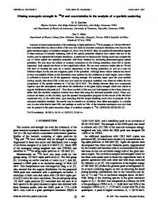
asynchronously read from any number of client applications simultaneously. This solution offers a number of advantages. First, we can use the same strategy, and topology, for both distributing live data and storing history data as shown in Fig. 1. Data sets that need to be updated are identically pushed, by front-end controllers, to both DOC and KVDB servers by issuing set commands. It means that the data collection mechanism for DAQ is inherently included in the !CHAOS communication framework because both live and history data are pushed by the data source (the front-end controllers) to similarly distributed caching and storage systems. Moreover, since both DOC and KVDB use key/value data storage, formatting and serialization of data sets can be done once for both. Second, both the client applications and the front-end controllers are simple clients of the distributed object caching and DAQ. In particular, provided the DOC has an object container for each data set of the DCS, defined by its unique key, a graphical user interface (GUI) client simply sends to the !CHAOS DOC service a get request for the object identified by that particular key, i.e., the data set describing the associated device. On the other side the controller responsible for that device updates the correspondent data set, according to the push rate defined for it, by issuing set commands to the DOC. Data refresh rates, as well as other metadata and global parameters, will be managed by the metadata server (MDS) that will be described later.
FIG. 1. Data flow in the !CHAOS framework.
112804-2
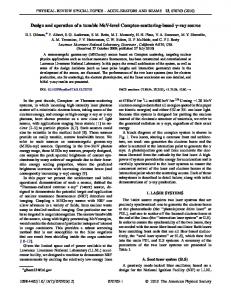
INTRODUCING A NEW PARADIGM FOR ACCELERATORS . . . It is worth mentioning that in !CHAOS the DOC layer is not operated as an object caching in a strict sense since the distributed memory is not populated after clients’ requests. Instead, each data set (i.e. the value paired to the DOC key) is by default stored in the DOC and continuously updated by the front-end controllers. Nevertheless, the data sets transfer from front-end to clients can still profit from the high performance of the distributed caching systems that, in addition, prevents front-end controllers from overload originated by multiple clients’ requests. Another benefit of the !CHAOS design is that the frontend controllers do not need to run servers to provide data to clients since they themselves are clients of the data distribution and storage services. That improves their robustness and portability. A fundamental property of both DOCs and KVDBs is their intrinsic scalability that allows distributing a single service over several computers. Moreover, dynamical keys redistribution allows automatic failover by redirecting to other servers the load of a failed one. By taking advantage of this feature !CHAOS can be easily scaled according to both the different size of the accelerator infrastructure and the performance required, thus avoiding any potential bottleneck that may be expected as the weakest link of the starlike communication topology. The data-pushing strategy allows one to further extend the abstraction boundary at the front end. The controller’s functionalities can be simplified and standardized by introducing the control unit (see next paragraph), a manager and a supervisor of the software modules implementing the device’s specific control procedures. In addition, abstraction of services will be implemented throughout (Fig. 2). Access to live or history data, for instance, will be provided by !CHAOS application programming interfaces (APIs) wrapping the service specific APIs in such a way that the client’s access to services, and even internal communications, will not be affected by the modification or replacement of any core component. Serializations of data sets and of information passed between components (e.g. command’s parameters, result of queries, etc.) will further improve the abstraction of services by using a binary string as the common format for the methods’ payload. The commands dispatching and the events notification services complement the communication and interconnection between !CHAOS components. A cross-language RPC-like software (i.e. MSGPACK [6]), included in the !CHAOS libraries, will be used by client applications for sending commands to front-end controllers. A convenient and efficient solution for events notification is IP multicast. Multicast is managed by routers creating optimal distribution paths for datagrams that can be sent to a group of destination computers simultaneously in a single transmission from the source. This is the technique chosen in !CHAOS for notification of events like alarms, reconfiguration of services, etc. In a multicast transmission
Phys. Rev. ST Accel. Beams 15, 112804 (2012)
FIG. 2. Abstraction boundary and abstraction of services in the !CHAOS framework.
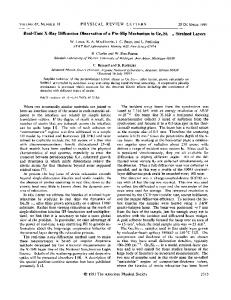
the source of the event does not require prior knowledge of who or how many receivers there are. It will be the components’ responsibility to subscribe to that and other classes of events for which they wish to be notified (e.g. concerning a service, a particular component, etc.). In conclusion, !CHAOS is a scalable control system framework providing, at a high level of abstraction, all the services needed for communication, data archiving, timing, etc.; GUI applications and front-end controllers access the framework services and expand its functionalities. A. Control units: The !CHAOS front end Figure 3 shows the logical structure of the software running in a front-end controller. The control unit (CU), the CU Toolkit, and the included Common Toolkit are components of the !CHAOS framework while the device management modules (DMM) are software modules that complement the !CHAOS framework functionalities by providing the interface to the device. The development of these components is expected either as a contribution, or as a responsibility, of the device experts. One or more instances of CU can run simultaneously, although completely independent, in a front-end controller. Each CU will be dedicated to a particular device or a family of devices and specialized for that particular component by means of appropriated device management modules. The latter is a set of routines implementing the device’s specific functionalities grouped into five general modules: initialization, deinitialization, control loop, data set update, and commands execution.
112804-3
L. CATANI et al.
FIG. 3.
Phys. Rev. ST Accel. Beams 15, 112804 (2012)
!CHAOS components for the front-end controllers.
The CU Toolkit, by means of its managers, will provide both the environment for the execution of the control units and the APIs needed to access the centralized services (DOC, KVDB, MDS). Since the CU will control the execution of DMMs, the former will be responsible for invoking the data set update module, according to the refresh rate defined for that device, in turn reading the device status. The data returned will be used by the CU, via the CU Toolkit, to feed the KVDB and to refresh the value of the correspondent key/ value pair in the distributed object caching service. It is worth mentioning that the CU can also be configured to either skip pushing a new data set to DOC and KVDB if its value has not significantly changed since the last update or to update it according to a push rate controlled by an external trigger signal. On the other hand, when a command issued by a client application is received by the CU, the command execution module will be invoked for executing it. The command is delivered to the CU Toolkit running the command server for all the CUs managed by that particular controller. When a command is received the CU Toolkit, by analyzing its domain, identifies the CU to which it is targeted and appends it to the correspondent command’s queue. In this case the MSGPACK call ends without error and the client application can follow the execution of the command and display the final result by pulling the device’s data set from DOC. If the application issuing the command requires a direct readback from the CU, this can be provided by returning the command’s results to the client’s call. Alternatively, since also the UI Toolkit will host a MSGPACK server, the client application could be notified, yet asynchronously, on
the results of the command’s execution by a message delivered from the CU. The latter, actually, is the preferred solution. Upon receipt of the command, the CU verifies that the method alias indicated in the command’s header is available and it can be executed (i.e. there is no other blocking method pending) and then launches the commands execution module. The rest of the serialized information containing the instructions for the action to be taken is passed as it is to the command’s execution module. The implementation of separated threads assures that requested periodicity of data set refreshing is preserved even during any commands’ execution. In addition, the serialization of the command’s descriptor (i.e. the command’s header, method name, parameters, etc.) passed to the execution module allows a common interface for all the methods to be implemented. A CU lock mechanism will be implemented for preventing execution of commands while previous ones, not yet completed, are still in operation on the same or related device attributes. During the command execution, if needed, the refresh rate of the device can be set, at least temporary, to a higher value providing the operator and the history data archiving system with a more detailed description of the attribute evolution. Modification of parameters like the data refresh rate are superintended by the metadata server. Control units or client applications can request their modification by issuing a command to the MDS. All components concerned with this change will receive notification by means of the events notification system. B. Live data caching Caching of live data, by means of a distributed object caching service, and continuous archiving of accelerator data, by using a distributed key/value database, are the main innovations introduced by the !CHAOS paradigm. DOC service is distributed over many nodes working together to provide clients with a virtual single pool of solid-state memory by sharing a portion of the RAM of each node. Objects are stored in memory as key/value pairs and a given object is always stored and always retrieved from the same node in the cluster, unless the number of the node changes for any reason. In !CHAOS a DOC’s key identifies a unique data set of the control system that is the set of information used to fully describe either a real or virtual accelerator device, e.g., a group thereof. Each data set is periodically refreshed by the control unit in charge of the corresponding device. In the DOC service, data set refreshing means overwriting the old data, i.e., the value paired with the device’s key, with newer data describing the actual state of the device. Refresh rates are set and
112804-4
INTRODUCING A NEW PARADIGM FOR ACCELERATORS . . . adjusted independently for each device and typical values span from milliseconds to a few seconds. Abstraction of live data, similarly to other !CHAOS services, allows not only the replacement of those libraries and software packages implementing the core service with others, but also the coexistence of two or more different technologies for implementing the same service. As an example consider an application requiring a more performant, quasideterministic distribution of live data. It could be, for instance, a measurement application or a feedback loop that needs to collect data sets from different CUs to perform calculations at rates higher than a few kHz. In this case a system based on reflective memory boards, having latency in the order of � sec , could be used to pass data, by mirroring memory locations, from the units controlling the diagnostic devices to those performing calculations. Remarkably, the use of this solution instead of the DOC will be completely hidden to developers of device management modules. Since the CUs implement and abstract the live data service they will be notified, by means of configuration parameters included in the device’s data set, to use APIs for the reflective memory boards instead of the distributed object caching for pushing live data. Simultaneously, the APIs will push the same data also to the distributed object caching service for making it available to other the components of the control system. C. DAQ Similarly to DOC, for the DAQ key/value pairs are pushed to a node of the distributed KVDB to be stored on its disks. In this case the encoded key contains both the unique data set indicator and the time stamp. By querying the DAQ for all the data sets corresponding to a given time stamp, the status of the accelerator at that particular time can be recovered. The time stamp is provided by the internal clock of the controller’s CPU via the operating system. For the !CHAOS DAQ, i.e., the continuous archiving system, we assumed a granularity of 20 msec corresponding to a maximum data set’s archiving rate of 50 Hz. This figure represents the time resolution of the !CHAOS DAQ, the level of details provided in reproducing the time evolution of each control system’s data set. In other words, a given data set can be archived in the DAQ with a frequency up to 50 Hz, which means a new key/ value pair for that data set is written in the KVDB every 20 msec. Coherency of data set’s time stamps must be guaranteed by achieving an accuracy of CPU’s synchronization better than the time resolution. If so, data sets stored in the DAQ with a given time stamp could be either joined to coherently reproduce the status of the accelerator at that particular time, or compared to find correlations in their time evolution.
Phys. Rev. ST Accel. Beams 15, 112804 (2012) D. Synchronization and timing
Either network time protocol or precision time protocol (PTP) could be implemented, the latter offering a much better resolution, to achieve the synchronization required for the distributed !CHAOS components. A more likely time stamp will be obtained from the timing/triggering system providing precise timing reference and events distribution for hardware components, I/O modules, and procedures. Preliminary tests with PTP have been performed by using a number of PCs and servers in the university network. Results confirmed that a synchronization better than 1 ms could be achieved between internal clocks of !CHAOS servers and control units. This figure goes beyond the minimum value expected for data refresh intervals in !CHAOS suggesting that granularity can be improved to hundreds of Hz or more. Nevertheless, additional time stamps, or event’s tags, can be included as secondary keys for the KVDB in the data set serialization to improve the DAQ time resolution. This will be the case, for instance, of signals acquired from ultrafast diagnostics providing measurement of a single bunch of the beam. Encoded in the primary key, the ‘‘main’’ time stamp, provided by the computer’s internal clock, will define the coarse time window used for fast querying, while the secondary key, providing either the bunch number or the event tag, will give detailed timing information. Selection of the timing/triggering solution, and its integration in !CHAOS, is currently under study. The open hardware project named ‘‘White Rabbit,’’ from CERN [7], is currently being considered as a possible candidate or a valuable reference for selecting the best solution. E. Data serialization A key feature of !CHAOS is the solution used to format data for either storage into either DOC or KVDB or communication between its different components. Binary serialization is a convenient solution for flattening even a complex data structure into a one-dimensional stream of bits suited for transmission through the network. It is well suited especially for large binary arrays that are frequently included in data sets of accelerator’s components [8]. What is more, both DOC and KVDB allow binary serialized data. In !CHAOS, BSON [9] serialization is used for encoding data set to be stored both in the live data DOC and in the DAQ. BSON serialization is also used by the UI toolkit (see next section) for formatting commands sent to front-end control units and for passing parameters between CU and device management modules. The software opted for implementing the DOC and the KVDB are MEMCACHED [10] and MONGODB [11], respectively. They demonstrated to offer the required features and performances and are supported by a large and growing
112804-5
L. CATANI et al.
Phys. Rev. ST Accel. Beams 15, 112804 (2012)
community of users. Nevertheless, the abstraction of services provided by the !CHAOS components would allow their replacement, with other implementation of DOC and KVDB, without any modification of both its functionalities and API calls. F. Metadata server Another fundamental component in the !CHAOS framework is the metadata server (Fig. 4). It is designed to store and provide the !CHAOS services with information such as CU configuration, commands list, commands and data syntax and semantic, naming service, etc. Object relational mapping packages will be employed to abstract the relational database, used for storing metadata, by mapping its tables into Java object. The metadata server will be also the central authority for !CHAOS components. It will keep track, for instance, of the control units instantiations. As supervisor of their initialization, it will manage, at start-up, the registration of CUs’ services and data sets providing them with a systemwide unique reference to be properly addressed by client applications. Information managed by the MDS will be stored in a conventional, compared to the KVDB used for the DAQ, relational database distributed over a cluster of servers for scalability and availability. A cluster of Tomcat servers will implement the front-end layer of the MDS. G. Scalability and failover It has been already mentioned that the !CHAOS framework is designed to easily adapt its size and performance to requirements of the accelerators’ infrastructure by taking advantage of scalability of its core components.
FIG. 4. The !CHAOS metadata server.
In the case of live data service, the scalability is inherent in the data object caching technology. In a cluster of DOC servers each single instance is running independently such that they are not aware of being members of a cluster. Instead, the distribution of keys among the different servers is managed by clients that, by following a common rule, write (read) key/value pairs to (from) the server they recognize as liable for that particular key. A simple strategy, commonly used for load distribution and failover, consists in ordering and equally dividing the keys among the servers by using an algorithm, provided as part of the client software, that at system startup, creates a hash table mapping the keys to the servers in the cluster. As an example, assuming that keys of our key/value pairs are represented by series of digits and that the cluster of the DOC service is composed of five nodes, the algorithm would assign to server #1 keys beginning with ‘‘0’’ and ‘‘1’’, to server #2 keys beginning with ‘‘2’’ and ‘‘3’’, and so on. Provided the key values are more or less randomly distributed, they will also be equally distributed among servers. If one of the servers fails then its block of keys will be automatically assigned to the preceding one, the last server being precedent to the first. This rule becomes more clear if we imagine the key space as a continuum where keys are distributed along a circumference that is virtually divided in equal sectors identifying key ranges assigned to each server in the cluster. For instance, if server #2 fails then writes (reads) to (from) keys beginning with ‘‘2’’ and ‘‘3’’ will be addressed to server #1; if #1 fails then the back-up node will be server #5, and so on. Clearly, the back-up server should be able to support, at least temporarily, this extra load. While this simple scalability and failover strategy works well for object caching applied to internet services, it is not the optimum for !CHAOS requirements. Among the possible alternatives we are currently working on a solution that can be summarized as the following. Data set assignment (i.e. distribution of keys) to MEMCACHED servers is managed by the MDS that provides control units and user interface toolkits with the list of primary and secondary servers for each data set. In the case of failure of a primary server both writing (typically CUs) and reading clients automatically switch to the first secondary server in the list and then to the following one in case the latter also fails. To achieve balancing between the servers, data sets are distributed by taking into account the product ðdata set sizeÞ � ðnominal refresh rateÞ such that bytes per seconds written to each server will be uniformly distributed. Also, secondary keys will be chosen to preserve a reasonable balancing in case of failure of one or more servers in the cluster. In the case of failure, switching from one server to another might result in data loss if the data set refresh rate is set to values higher than 100 Hz. We expect the
112804-6
INTRODUCING A NEW PARADIGM FOR ACCELERATORS . . . time needed to migrate to a secondary MEMCACHED server to be in the order of 10 milliseconds or less. This figure corresponds to the value that will be set as the timeout of network connections. It will depend on the average load of both the servers and the network during operations. In the cases where a loss of even a single data set update cannot be tolerated, as for synchronized measurements, we introduced in the control unit a circular buffer for each of these data sets to store locally the N most recent updates, N being approximately inversely proportional to the refresh rate. The whole circular buffer, containing the last N key/ value couples for the data set, is then written at each refresh to the DOC instead of just the last one. In case of failure of a primary server, even if the time needed for switching to the back-up server takes longer than the refresh period, the client will find in the new location, not just the last update but also the previous N-1 ones, including the update(s) that might have been lost during the switching operation. Scalability and availability of the metadata server will be implemented by following a similar strategy. A number of Tomcat servers are used as distributed and scalable MDS access points. A service running on a minimal http server assigns them as primary or secondaries to each control unit at the startup. It can be a simple PHP script that replies to the CU request with a list of ordered IP addresses of correspondent MDS access points (the first IP is the primary MDS for that CU, and so on). The list can be created at each request by using a simple round-robin assignment that equally distributes Tomcat nodes as primary MDS servers of the CUs. The Tomcat front end implements also the abstraction layer for the relational database underneath. They receive queries formulated in the !CHAOS query language and translate them into commands for the relational database management system (RDBM). Moreover, scalability and availability are built-in features of many RDBM distributions (e.g. [12]). H. User interface toolkit Client access to !CHAOS services will be uniquely allowed by means of the APIs provided by the user interface (UI) toolkit, the set of API aiming to abstract and simplify the access of client applications to the !CHAOS service. Figure 5 shows the logical structure of the UI toolkit layers with the blocks of API to client application and the substrate of API for the abstraction of the !CHAOS services. Also introduced in the figure is the concept of UI data cache we are currently developing to achieve further improvement of the UI toolkit performance. It practically consists of an internal caching system for data and metadata where UI toolkit APIs store and share both frequently used metadata, produced by queries to MDS, and live data read from the distributed object cache. Similarly to distributed live data caching, we are considering a solution based on a key/value object caching to
Phys. Rev. ST Accel. Beams 15, 112804 (2012)
FIG. 5.
The user interface toolkit components.
store this information locally. Caching of live data will take into account the refresh rate of the particular device data set for setting its expiration time. I. Programming languages and interfaces to other applications While most of the !CHAOS code is written in C, C++, and Java, development of both client applications and device management modules should include a larger selection of programming languages. Since at INFN-LNF and INFN-Roma Tor Vergata there is a long tradition in developing control and data acquisition systems with National Instruments LabVIEW, we already started remodeling existing front-end software to adapt it to !CHAOS DMM requirements. On the client side, UI toolkit will provide APIs for most common measurement and analysis software like Matlab and the before mentioned LabVIEW. III. TESTING !CHAOS COMPONENTS Scalability of distributed object caching systems should, in principle, safely prevent limitation in the speed and rate of data transfer between components in !CHAOS provided the number of servers in the DOC cluster is sized to fit requirements. Nevertheless, an evaluation of performance is needed if, in the design phase especially, a user is willing to guess the best data transfer speed and throughput achievable for a certain configuration of the system and for a given set of working conditions. For MEMCACHED in particular, due to the large community of users and the number of internet services based on this software, quite a vast collection of reports on performance tests is available. The tests, carried out in different conditions and with a different selection of hardware,
112804-7
L. CATANI et al.
Phys. Rev. ST Accel. Beams 15, 112804 (2012)
provide results confirming excellent performance, showing a very high throughput in both reading and writing data, or objects, of different size. Actually, as required from its application in highperformance internet web services, those tests mainly focus on measuring the ability of MEMCACHED distributed servers of managing the increasing number of client connections while preserving the same speed in completing users’ requests or comparing its performance against benchmarks for equipollent internet technologies. Since our use of MEMCACHED is a bit unconventional these tests, although important for confirming some of its relevant functioning, are not sufficient to fully exploit the performance we consider to be critical for its application in !CHAOS. The most relevant is the speed in data writing and reading such that any data set generated at a CU level can be written on MEMCACHED and, afterwords, asynchronously read and delivered to a client application in a few milliseconds. This figure should be reproducible and remain constant in all the operation conditions to guarantee a nominal refresh rate of 50 Hz for all standard data sets, which means excluding very large ones like, for instance, full size digital images. Different conditions include simultaneous reading of the same data set from a different number of multiple clients or, more generally, different server load and/or network traffic. A number of tests have been performed to obtain measurements of data transfer speed in simulated working conditions. We used a 2.66 GHz quad-core server with 16 GB RAM running MEMCACHED v1.4.5 and simulated a number of CU with concurrent processes writing data sets of different size with different refresh rates. We changed data set size from 0.1 to 100 KB, concurrent writing and reading processes from 20 to 80 independently and refresh rate from 10 to 100 Hz. In all the conditions we verified that data received by the client application
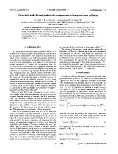
FIG. 6.
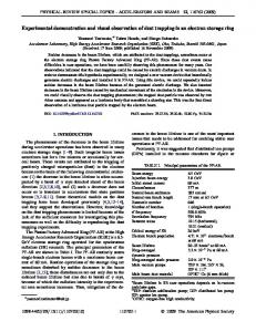
were not older than the expected value for the set refresh rate. The most significant result is shown in Fig. 6. Dots in the graph on the left side show a representative sample of a measurement of the time difference between the data set time stamp, written by the process simulating the CU, and the time at which the data set was received by the client application, both processes running asynchronously at 50 Hz. With the data set size set to 100 KB, 20 writing processes practically saturated the 1 Gb Ethernet interface of the MEMCACHED server (100 MB=s of payload plus Ethernet headers ffi 1 Gb=s). Despite this heavy load, the four cores of the CPU were running almost free, showing occupancy not exceeding an average value of 9%. In these operating conditions, as shown by the histogram on the right side, the measured data transfer times produced an almost uniform distribution in the range 0–20 ms, thus demonstrating the possibility to achieve the expected refresh rate even in these extreme conditions. Looking at the histogram more carefully, one can notice that values actually span from about 2 ms to around 25 ms. It can be easily concluded that the lower value represents the minimum time needed for transferring data from CU to client application including, besides the network time transfer, the time elapsed for serializing the data set at the source and the deserialization at destination. Similarly, the measurements exceeding 20 ms give a hint on the maximum transfer time estimated, for the specified measurement conditions, equal to approximately 5 ms. It is worth emphasizing that, in our case, performance surely benefits from the constant size of data sets. In fact, once a given key/value pair has been allocated in the server memory it will remain constant in size and location because, different from web objects, it does not change its data types and consequently the size but changes only its
Measured transfer time of data sets between a front-end CU and a client application via DOC.
112804-8
INTRODUCING A NEW PARADIGM FOR ACCELERATORS . . .
Phys. Rev. ST Accel. Beams 15, 112804 (2012)
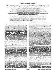
FIG. 7. Measured transfer time between front-end CU and a client application via DOC for a different number of concurrent clients reading the same key/value being continuously updated by the CU.
values thus preventing MEMCACHED from wasting time with memory chunks resizing and reshuffling. Figure 7 shows the results of another set of measurements we performed to study the CU-client transfer time in the case where a number of clients were reading the same data set while the CU was continuously updating it. In this test we stressed the MEMCACHED ability in handling concurrent read/write operations from/to the same key/value pair. In particular, we wanted to verify if during a write operation of a key/value pair, i.e., a refresh of a data set, the resulting lock of the correspondent memory block would effect the performance of one or more clients reading the same key. Using the same hardware setup of the previous measurements, we ran a CU simulator configured to refresh a given key/value, having a size of 100 Bytes, at a frequency of 1 kHz. On the other side a number of independent clients were simultaneously and asynchronously reading the same key/value at a frequency of 100 Hz. The four plots, similar to Fig. 6, show the distribution of the trip time between front-end CU and the client applications for a different number of simultaneous clients from 5 (top) to 40 (bottom).
By comparing the four histograms, we can conclude that performance does not significantly depend on the number of simultaneous clients. In turn that means the memory lock operated by MEMCACHED during the write procedure does not affect the read performance appreciably. Nevertheless, some little differences can be evidence at the tails of the distribution (shaded areas). At the lower end, the 0-1 bin decreases its population when the number of clients rises meaning that the number of short trip time, i.e. � 1 ms or less, diminishes. At the other end, the tail of the distribution gradually populate bins � 12 ms, which means relatively long trip time, i.e. � 3 ms or higher, are more frequent as the number of clients increases. We conclude mentioning that, after the convincing results obtained with these tests, the control groups of Dafne [13] and SPARC [14] accelerators at INFN-LNF decided to introduce the MEMCACHED-based communication in their control systems, initially limited to selected subsets of components. These installations offered a great opportunity for testing in the field this crucial service of the !CHAOS framework and provided very important information confirming its performance and reliability.
112804-9
L. CATANI et al.
Phys. Rev. ST Accel. Beams 15, 112804 (2012)
Moreover, in the case of SPARC, this solution is now planned as a systemwide replacement of the former clientserver communication protocol and progressively extended to the remaining components of the control system.
the development of this conceptual design, validating its functionalities and performance, and candidate !CHAOS as the control system for future INFN particle accelerators.
IV. CONCLUSION !CHAOS is a scalable control system framework providing all the services needed for communication, data archiving, timing, etc., in a control system for a particle accelerator and/or any other large apparatus. Front-end controllers, GUI, measurement applications, etc., can be seen either as clients that access its services or as components that expand its functionalities. The innovative communication framework is based on a distributed object caching service while continuous archiving of data is implemented by means of a nonrelational distributed key/value database. The use of the before mentioned software technologies introduces a new paradigm of control system in which the two layers representing the front end and the clients level are complemented by a third intermediate layer that coordinates the whole system by collecting and distributing data, commands, events, etc. This intermediate layer is implemented by the !CHAOS framework. It provides a general class of clients with all functionalities needed for implementing a control system. For this reason we define it as the ‘‘control server.’’ Serialization of the information and a high level of abstraction of services and components allow extending the boundaries of the !CHAOS framework in such a way to reduce the complexity and the amount of software development required to users. The !CHAOS collaboration groups at INFN-LNF and INFN-Roma Tor Vergata are committed to finalizing
[1] M. Giorgi et al., Report No. SuperB-CDR2 INFN-LNF11/9(P), 2011. [2] http://chaos.infn.it. [3] G. Mazzitelli et al., in Proceedings of IPAC2011, San Sebastian, Spain (EPS-AG, Spain, 2011), pp. 2322–2324 [http://www.JACoW.org]. [4] L. Catani et al., in Proceedings of ICALEPCS 2011, Grenoble, France, pp. 856–859, ISSN 2226-0358 [http:// www.JACoW.org]. [5] M. E. Thuot and L. R. Dalesio, in Proceedings of the Particle Accelerator Conference, Washington, DC, 1993 (IEEE, New York, 1993), p. 1806. [6] http://msgpack.org. [7] http://www.ohwr.org/projects/white-rabbit. [8] Luciano Catani, Extending LabVIEW Aptitude for Distributed Controls and Data Acquisition, LabVIEW— Practical Applications and Solutions, edited by Folea Silviu, ISBN: 978-953-307-650-8 [http://www.intechopen .com/articles/show/title/extending-labview-aptitude-fordistributed-controls-and-data-acquisition]. [9] http://bsonspec.org. [10] http://memcached.org. [11] http://www.mongodb.org. [12] http://www.mysql.com/products/cluster/. [13] G. Di Pirro, C. Milardi, A. Stecchi, and L. Trasatti, Nucl. Instrum. Methods Phys. Res., Sect. A 352, 455 (1994). [14] F. Anelli et al., in Proceedings of ICALEPCS 2009, Kobe, Japan (2009), pp. 747–749, ISBN 978-4-9905391-0-8 [http:// www.JACoW.org].
112804-10