INTRODUCTION Welcome to the Proceedings of the 8th Workshop on Targetry and Target Chemistry, which was held in St. Louis during the summer of 1999. The workshop was held concurrently with the 11th International Symposium on Radiopharmacology (ISR) and immediately prior to the 13th International Symposium on Radiopharmaceutical Chemistry (ISRC). Together they represented “Meetings in St. Louis,” which was devoted to all aspects of radiopharmaceutical development. In all, the meetings were attended by a total of 600 scientists and engineers from many countries throughout the world. These proceedings represent joint efforts by many people, most importantly of which are the many scientists and engineers who participated in the workshop itself. Without this input and level of enthusiasm the workshop would fail in its mission. Organizing the workshop was a major challenge and I would like to thank the Local Organizing Committee and the International Advisory Committee for their guidance and encouragement. I must also acknowledge the hard work of the Global Steering Committee for Meetings in St. Louis, who met every Thursday for two years prior to the meetings and ensured that the entire infrastructure was in place for successful scientific interaction. I am deeply grateful to all of the session chairs, whom I begged, bullied and coerced into organizing sessions, moderating and proofreading the transcripts of the sessions. Their efforts are well reflected in these proceedings. We are in the process of archiving all of the WTTC proceedings to the Internet; they will be available through TRIUMF (www.triumf.ca/wttc). Finally, I would like to wish Olof Solin and the local organizing committee every success with the Ninth Workshop, which will be held in Turku, Finland, in May 2002.
Timothy J. McCarthy Editor
Contents Organizing Committees . . . . . . . . . . . . . . . . . . . . . . . . . . . . . . . . . . . . . . . . . . . . . . . . . . . . . . . . . . . . . . . .VI Meeting Schedule . . . . . . . . . . . . . . . . . . . . . . . . . . . . . . . . . . . . . . . . . . . . . . . . . . . . . . . . . . . . . . . . . . . . .VII List of Sponsors . . . . . . . . . . . . . . . . . . . . . . . . . . . . . . . . . . . . . . . . . . . . . . . . . . . . . . . . . . . . . . . . . . . . .VIII Accelerators Organizers: Jeanne M. Link and Ruth Shefer. . . . . . . . . . . . . . . . . . . . . . . . . . . . . . . . . . . . . . . . . . . . . . . . .1 Introduction to the Session. J. Link. University of Washington, Seattle, WA, USA . . . . . . . . . . . . . . . . . . . . .2 INVITED TALK: Liquid Gallium Cooling of a High-Power Beryllium Target for Use in Accelerator Boron Neutron Capture Therapy (ABCNT). J.C. Yanch. Nuclear Engineering Department Department and Whitaker College of Health Sciences and Technology MIT, Cambridge, MA, USA . . . . . . . . . . . . .3 New developments in cyclotrons at CTI. B. Alvord. CTI, Inc, Knoxville, TN, USA . . . . . . . . . . . . . . . . . . . .6 Liquid gallium cooling of a high-power beryllium target for use in accelerator boron neutron capture therapy (ABCNT). B.W. Blackburn and J.C. Yanch. Nuclear Engineering Department, MIT, Cambridge, MA, USA . . . . . . . . . . . . . . . . . . . . . . . . . . . . . . . . . . . . . . . . . . . . . . . . . . . . . . .7 Feasibility study of 149Tb production at the Tesla accelerator installation. M. Dakovic and J.J. Comor Vin_a Institute of Nuclear Sciences, Belgrade, Yugoslavia. . . . . . . . . . . . . . . . . . . . . . . . . . . . . . . . . . . . . . . .10 Developments at EBCO. K. Erdman, EBCO Technologies, Inc. Richmond, BC, Canada. . . . . . . . . . . . . . . .13 A summary of TCA developments since placed in service at Washington University. G.G. Gaehle and M.J. Welch. Washington University, St. Louis, MO, USA. . . . . . . . . . . . . . . . . . . . . . . . . . . . . . . . . . . . .14 Progress report on the development of a fluorine-18 production target for the AccSys Pulsar(tm) system. R. Hamm and G. Robinson, Jr. AccSys Technologies, Inc., Pleasanton, CA, USA . . . . . . . . . . . . . . .16 Summary report on evaluation of the 10.5 MeV 3He RFQ accelerator. K.A. Krohn, J.M. Link, P.E. Young, R. DeHaas, D.J. Larson and R.J. Pasquinelli. University of Washington, Seattle, WA, USA . . . . .17 Isotope production at International Isotopes, Inc. I.L. Morgan, H. Hupf, G. King and J. Armbruster. International Isotopes, Denton, TX, USA . . . . . . . . . . . . . . . . . . . . . . . . . . . . . . . . . . . . . . . .21 A second target station for the bombardment of semi-permanent targets at the national accelerator centre. F.M. Nortier, P.J. Binns, J. Hanekom, M.A. Penny, R.E. Quantrill, H.A. Smit, T.J. van Rooyen and V.M.P. Xulubana. National Accelerator Centre, Faure, South Africa . . . . . . . . . . . .22 MINItraceTM tracer production system - a work in progress. M. Orbe, GE Medical Systems, Uppsala, Sweden . . .23 The new ISAC facility at TRIUMF. T.J. Ruth. TRIUMF, Vancouver, BC, Canada . . . . . . . . . . . . . . . . . . . .25 Overview of Accelerator Development at NSI. Robert E. Klinkowstein, Ruth E. Shefer, and Barbara J. Hughey. Newton Scientific, Inc., Cambridge, MA, USA . . . . . . . . . . . . . . . . . . . . . . . . . . . . . . . . . . . . . . . . .26 Compact LINAC Systems for Medical Applications. W.J. Starling. Linac Systems, Waxahachie, TX, USA. . . . .28 IBA developments in the field of accelerators. R. Verbruggen, F. Schmitz, M. Ghyoot, F. Vamecq and Y. Jongen. Ion Beam Applications, Louvain la Neuve, Belgium . . . . . . . . . . . . . . . . . . . . . . . . . . . . . . . .29
I
High Yield [18F]fluoride Production Organizers: John C. Clark and Stefan K. Zeisler. . . . . . . . . . . . . . . . . . . . . . . . . . . . . . . . . . . . . . . . . . . . . . .31 Introduction. J.C. Clark, University of Cambridge, UK. . . . . . . . . . . . . . . . . . . . . . . . . . . . . . . . . . . . . . . . .32 High yield [O-18]water target for [F-18]fluoride production on MC-17 cyclotrons. M.S. Berridge, K.W. Voekler and B.J. Bennington. Case Western Reserve University and, University Hospitals of Cleveland. Cleveland, OH, USA . . . . . . . . . . . . . . . . . . . . . . . . . . . . . . . . . . . . . . . . . . . . . . . . . . . . . . . . . .34 Some optimisation studies on the production of [18F]F2 via the 18O(p,n)18F process. E. Hess, G. Blessing, H.H. Coenen and S.M. Qaim. Institüt für Nuklearchemie, Jülich, Germany . . . . . . . . . . . . . . . . . .38 Targetry for the production of ultra high quantities of 18F-fluoride: a work inprogress. T.J. Ruth, K.R. Buckley, E.T. Hurtado, J. Huser, S. Jivan, K.S. Chun and S.Zeisler. TRIUMF, Vancouver, Canada; Korean Cancer Center Hospital, Seoul, S. Korea; and DKFZ, Heidelberg, Germany. . . . . . . . . . . . .41 Multicurie fluoride-18 in IBA titanium target. P. van der Jagt, P. van Leuffen, F. van Langevelde, P. Kruijer, M. Ghyoot, F. Schmitz, R. Verbruggen F. Vamecq, C. Destexhe and Y. Jongen. BV Cyclotron VU and IBA, Louvain la Neuve, Belgium . . . . . . . . . . . . . . . . . . . . . . . . . . . . . . . . . . . . . . . . . . . . . . . . . . .44 Production of [18F]fluoride in a water-cooled spherical niobium target. S.K. Zeisler, D.W. Becker and R.A. Pavan. German Cancer Research Center, DKFZ, Heidelberg, Germany and TRIUMF, Vancouver, Canada . . . . .48 Further discussion of other commercial [18F]fluoride targets . . . . . . . . . . . . . . . . . . . . . . . . . . . . . . . . . . .52
Automation Organizers: Richard Ehrenkaufer and James P. O’Neil. . . . . . . . . . . . . . . . . . . . . . . . . . . . . . . . . . . . . . . . . .57 Introduction to the Session. Richard Ehrenkaufer. Wake Forest University Baptist Medical Center, Winston-Salem, NC, USA . . . . . . . . . . . . . . . . . . . . . . . . . . . . . . . . . . . . . . . . . . . . . . . . . . . . . . . . . . . . . . .58 Radiopharmaceutical automation: sensors and technology vs. the human experience. R.D. Hichwa, University of Iowa, Iowa City, IA, USA . . . . . . . . . . . . . . . . . . . . . . . . . . . . . . . . . . . . . . . . . . . . . . . . . . . . .59 Chemistry system control with LOOKOUTTM control software. K.R. Buckley, TRIUMF, Vancouver, BC, Canada. . . . . . . . . . . . . . . . . . . . . . . . . . . . . . . . . . . . . . . . . . . . . . . . . . . . . . . . . . . . . . . . . . . . . . . . . . .61 Overview and application of compact, solid-state radiation detectors, L.R. Carroll. Carroll/Ramsey Assoc. Berkeley, CA, USA . . . . . . . . . . . . . . . . . . . . . . . . . . . . . . . . . . . . . . . . . . . . . . . . . . . . . . . . . . . . . . . .63 Heated nitrogen to rapidly evaporate solutions. J.B. Downer, W.H. Margenau and M.J. Welch. Washington University, St. Louis, MO, USA . . . . . . . . . . . . . . . . . . . . . . . . . . . . . . . . . . . . . . . . . . . . . . . . .64 Modeling radiation levels within the GEMS methyl iodide box as a way to predict I2 tube lifetime. R.A. Ferrieri, D.J. Schlyer and J.S. Fowler. Brookhaven National Laboratory, Upton, NY, USA . . . . . . . . . . .67 The development of an FDG module designed for the distribution setting. S. Zigler. CTI, Inc., Knoxville, TN, USA . . . . . . . . . . . . . . . . . . . . . . . . . . . . . . . . . . . . . . . . . . . . . . . . . . . . . . . . . . . . . . . . . . . ..69 A new synthesizer for the routine production of FDG using standard disposable components. C. Mosdzianowski and J-L. Morelle. Coincidence Technologies, Liége, Belgium. . . . . . . . . . . . . . . . . . . . . . .70 Developments in FDG synthesis and production. M. Jackson, Nuclear Interface, LLC, Jackson, TN, USA . . . .73 In-Line conductivity sensor measurement of irradiated target water during F-18 production, C.J. McKinney. Duke University Medical Center, Durham, NC, USA . . . . . . . . . . . . . . . . . . . . . . . . . . . . . . . . .75 II
On-Line measurement of the evolution of radiolysis gas from an F-18 Target. C.J. McKinney, M.F. Dailey and B.W. Wieland. Duke University Medical Center, Durham, NC, USA. . . . . . . . . . . . . . . . . . . . . .77 An alternative approach to filling and emptying syringes, external pressure rather than a syringe pump or piston. J.M. Link, K.A. Krohn. University of Washington, Seattle, WA, USA. . . . . . . . . . . . . . . . . .79 Integrating a high yield high-pressure water target from GE onto the CS-15 cyclotron at Washington University. G.G. Gaehle, W.H. Margenau and M.J. Welch. Washington University, St. Louis, MO, USA . . . .81 A peltier thermal cycling unit for rapid radiopharmaceutical synthesis. C.J. McKinney and M.W. Nader Department of Radiology, Duke University Medical Center, Durham, NC, USA . . . . . . . . . . . . . . . .83 A robust, miniature in-line monitoring systems for radioactive gas production. M.L. Renton, P.B. Burke, D.B. Mackay and A.S.O. Ranicar. MRC Cyclotron Unit, Hammersmith, London, UK . . . . . . . . . . . . . ..85 Medi-SMARTS On-line radiation monitoring system for PET laboratories. A. Osavitsky. Rotem Industries. Israel. . . . . . . . . . . . . . . . . . . . . . . . . . . . . . . . . . . . . . . . . . . . . . . . . . . . . . . . . . . . . . . . . . . . . .89 An advanced [15O]water infuser. H.T. Sipilia and K. Eklund. Turku PET Center, Turku, Finland. . . . . . . . .90 Noise and circuit analysis for the unbiased photodiode radiation detector. N.D. Solomonson, J.M. Link and K.A. Krohn. University of Washington, Seattle, WA, USA . . . . . . . . . . . . . . . . . . . . . . . . . . . . . . ..92 Semi-intelligent control of automated synthesis using a toshiba EX40+ PLC. C.J. Steel, M.L. Renton and V.W. Pike. Hammersmith Hospital, London, UK . . . . . . . . . . . . . . . . . . . . . . . . . . . . . . . . . . . ..95 A versatlie synthesis apparatus for easy automation. G. Westera, J.T. Patt, C.-O. Sjöberg, N. Schmidt and P.A. Schubiger. Center for Radiopharmaceutical Science, Paul Scherrer Institute, Zürich, Switzerland. . . . .98 Economical radioactivity measurement and dose dispensing. K.W. Voeckler and M.S. Berridge. University Hospitals of Cleveland and Case Western Reserve University, Cleveland, OH, USA. . . . . . . . . . .99 Basic hydrolysis of 2-[18F]fluoro-2-deoxy-1,3,4,6-tetra-O-acetyl-D-glucose on a silica support in the production of FDG. C.J. Steel and V.W. Pike. MRC Cyclotron Unit, Hammersmith Hospital, London, UK . . . . . . . . . . . . . . . . . . . . . . . . . . . . . . . . . . . . . . . . . . . . . . . . . . . . . . . . . . . . . . . . . . . . . . . . .101
Non-Standard Isotope Production Organizers: Timothy J. McCarthy and Syed Qaim. . . . . . . . . . . . . . . . . . . . . . . . . . . . . . . . . . . . . . . . . . . .103 Introduction to the Session. S. Qaim, Institut für Nuklearchemie, Jülich, Germany. . . . . . . . . . . . . . . . . .104 Measurement of excitation functions using a pellet method: cross-sections for 140Ce(p,xn). D.W. Becker and S.K. Zeisler. German Cancer Research Center (DKFZ), Heidelberg, Germany . . . . . . . . . . . . ..105 Carbon-10 gases wait for no man. M. Jensen, R.J. Nickles, S. Holm and M.J. Schueller. University of Wisconsin-Madison &, Madison, WI, USA . . . . . . . . . . . . . . . . . . . . . . . . . . . . . . . . . . . . . . . . . . . . . . . . ..108 An alternative route for the production of 103Pd. M. Fassbender, F.M. Nortier, I.W. Schroeder and T.N. van der Walt. National Accelerator Centre, Faure, South Africa . . . . . . . . . . . . . . . . . . . . . . . . . . . . . .111 Production of high quality palladium-103 on cyclotron. A.A. Razbash, N.N. Krasnov, Y.G. Sevastianov, N.A. Konyakhin, A.A. Ponomarev, V.N. Mironov and P.P. Dmitriev. Cyclotron Company, Obninsk, Russia. . . . .113 Europium-155 - Alternative to gadolinium-153?. A.A. Razbash and Y.G. Sevastianonv. Cyclotron Company, Obninsk, Russia . . . . . . . . . . . . . . . . . . . . . . . . . . . . . . . . . . . . . . . . . . . . . . . . . . . . . . . . . . . . . .114
III
Study of physico-chemical processes in sandstones by PET. P. Goethals PET-center UZ/RUG, Gent, Belgium, . . . . . . . . . . . . . . . . . . . . . . . . . . . . . . . . . . . . . . . . . . . . . . . . . . . . . . . . . . . . . . . . . . . . . .115 Preliminary results on the production of 66Ga, non-conventional positron emitter. J. Koziorowski, R.D. Finn, K.S. Pentlow, A. Lövqvist, Y. Sheh, M. McDevitt and S.M. Larson. Memorial SloanKettering Cancer Center, New York, NY, USA . . . . . . . . . . . . . . . . . . . . . . . . . . . . . . . . . . . . . . . . . . . . . . .117 Comparison of gallium-66 production methods for the development of automated processing systems. M.R. Lewis, R. Laforest, D.E. Reichert, W.H. Margenau, R.E. Shefer, R.E. Klinkowstein, B.J. Hughey and M.J. Welch. Washington University, St Louis, MO, and Newton Scientific, Inc, Cambridge, MA, USA. . . .120 Routine production of [75Br]bromide in a gas target. S.K. Zeisler and H. Gasper. German Cancer Research Center (DKFZ), Heidelberg, Germany. . . . . . . . . . . . . . . . . . . . . . . . . . . . . . . . . . . . . . . . . . . . . .124 Investigation of I-124, Br-76, and Br-77 production using a small biomedical cyclotron-can induction furnaces help in the preparation and separation of targets? T.J. McCarthy, R. Laforest, J.B. Downer, A.-R. Lo, R.E. Shefer, R.E. Klinkowstein, B.J. Hughey and M.J. Welch. Washington University, St Louis, MO, and Newton Scientific, Inc, Cambridge, MA, USA . . . . . . . . . . . . . . . . . . . . . . . . . . . . . . . . . . . . . . .127 Production of 124I at small and medium sized cyclotrons. S.M. Qaim, F.M. Nortier, G. Blessing, I.W. Schroeder, B. Scholten, T.N. vander Walt and H.H. Coenen. Institüt für Nucklearchemie, Jülich,Germany and National Accelerator Centre, Faure, South Africa . . . . . . . . . . . . . . . . . . . . . . . . . . . . . . . . . . . . . . . . .131 A facility for the safe recovery of high specific activities of iodine-124 produced by the 124Te(p,n)124 I reaction. D.J. Brown, D.B. Mackay, J. Coleman, S.K. Luthra, F. Brady, S.L. Waters and V.W. Pike. MRC Cyclotron Unit, Hammersmith Hospital, London, UK . . . . . . . . . . . . . . . . . . . . . . . . . . . . . . . . . . . .134 Solid targetry for cyclotron production of intermediate-lived radioisotopes. B.J. Hughey, R.E. Shefer and R.E. Klinkowstein. Newton Scientific, Inc. Cambridge, MA, USA . . . . . . . . . . . . . . . . . . . . . . ..137 Cobalt-55: targetry and production at energies less than 11 MeV. J.P. O’Neil and H.F. VanBrocklin. LBL Biomedical Isotope Facility, Berkely, CA, USA. . . . . . . . . . . . . . . . . . . . . . . . . . . . . . . . . . . . . . . . . . . .138 No carrier added separation of tellurium from antimony. V. Tolmachev and H. Lundqvist. Department of Chemistry, Uppsala University, Uppsala, Sweden. . . . . . . . . . . . . . . . . . . . . . . . . . . . . . . . . . . . . . . . . . .140 Direct comparison of ion-exchange and solvent extraction for separation of iron-52 from nickel target. V.Tolmachev and H. Lundqvist. Department of Chemistry, Uppsala University, Uppsala, Sweden . . . . . . .143
Reports from Laboratories Organizers: R. Jerry Nickles and Robert Dahl. . . . . . . . . . . . . . . . . . . . . . . . . . . . . . . . . . . . . . . . . . . . . . . .147 An overview of the PET facility in St. Petersburg. R. Krasikova, Russian Academy of Science, St. Petersburg, Russia. . . . . . . . . . . . . . . . . . . . . . . . . . . . . . . . . . . . . . . . . . . . . . . . . . . . . . . . . . . . . . . . . . . .148 International Nuclear target design society: report from the 19th world congress. J.P. O’Neil. Lawrence Berkeley National Laboratory, Berkeley, CA, USA. . . . . . . . . . . . . . . . . . . . . . . . . . . . . . . . . . . .150 The isotope production facility at Los Alamos National Laboratory. R.W. Atcher, R. Heaton, E.J. Peterson and the Isotope Production Team. Los Alamos National Laboratory, Los Alamos, NM, USA . . . .151 Radioactive ion beams at Lawrence Berkeley National Laboratory. J.P. O’Neil, H.F. VanBrocklin et al. Lawrence Berkeley National Laboratory, Berkeley, CA, USA. . . . . . . . . . . . . . . . . . . . . . . . . . . . . . . . . . . .152 Romanian radiopharmaceuticals market and the possibilities for supplying its demands. L. PopaSimil National Inst. For Nuclear Physics & Engineering, Bucharest-Magurele, Romania. . . . . . . . . . . . . . .154 Cyclone 18/9 & 10/5 user community - second workshop. St. Preusche, C. Dupont, R. Verbruggen, F. Vamecq, G. Bormans. Forschungzentrum Rossendorf, Dresden, Germany. . . . . . . . . . . . . . . . . . . . . . . . .155
IV
Targetry/In-Target Chemistry Organizers: Thomas J. Ruth and David Schlyer. . . . . . . . . . . . . . . . . . . . . . . . . . . . . . . . . . . . . . . . . . . . . .157 Introduction to the session. Tom Ruth, TRIUMF and David Schlyler, BNL . . . . . . . . . . . . . . . . . . . . . . .158 INVITED TALK, Relationship of Hot Atom Chemistry to PET Radionuclides Production. M.J. Welch, Washington University School of Medicine, St. Louis, MO, USA. . . . . . . . . . . . . . . . . . . . . . . . . . . .159 Neutron monitoring: a useful diagnostic tool for (p,n)- targets. G. Firnau, B. Alvord and D. Williams. McMaster University Medical Centre, Hamilton, ON, Canada and CTI, Inc, Knoxville, TN, USA . . . . . ..161 Tritium in [15O]water, its identification and method of removal. T. Sasaki, S. Ishii, K. Tomiyoshi, T. Ido, J. Miyauchi and M. Senda. Positron Medical Center, Tokyo, Japan . . . . . . . . . . . . . . . . . . . . . . . . . .165 Impurity “hot atoms” in a role a structure-sensitive physical-and-chemical probes with an estimation of a condition of the cyclotron targets after irradiation. I.E. Aleskeev, A.E. Antropov. State University, St. Petersburg, Russia. . . . . . . . . . . . . . . . . . . . . . . . . . . . . . . . . . . . . . . . . . . . . . . . . . . . . . . . . . . . . . . . . . .168 A pure 11CH4 production via 11B(p,n)11C reaction using sintered boron disc target. Al-Rayyes Hamid, Syrian Atomic Energy Commission of Syria, Damascus, Syria . . . . . . . . . . . . . . . . . . . . . . . . . . . .178 Methane Production in small volume, high pressure gas targets: further studies. K.R. Buckley, J. Huser, S. Jivan and T.J. Ruth. TRIUMF, Vancouver, BC, Canada. . . . . . . . . . . . . . . . . . . . . . . . . . . . . . .179 Irradiation of ammonia at liquid nitrogen temperatures: the mechanistic implications for direct production of [11C]HCN. M.L. Firouzbakht, D.J. Schlyer and J.S. Fowler. Brookhaven National Laboratory, Upton, NY, USA. . . . . . . . . . . . . . . . . . . . . . . . . . . . . . . . . . . . . . . . . . . . . . . . . . . . . . . . . . . . . . . . . . . . . . .182 A modified method to form [11C]methanol on a column for synthesis of [11C]methyl iodide. E. Priboczki-Sarkadi, Z. Kovacs, G. Horvath and P. Lehikoinen. Hungarian Academy of Sciences, Debrecen, Hungary and Abo Academi University, Turku, Finland. . . . . . . . . . . . . . . . . . . . . . . . . . . . . . . .184 Measurement of the specific activity of cyclotron-produced [11C]methane by capillary gas chromatography. C.J. Steel, S.K. Luthra, F. Brady and V.W. Pike. Hammersmith Hospital, London, UK . . . . . . . . . . . . . .186 Preparation of [11C]iodomethane with low levels of carbon-12 contamination using a GE MeI microlab. F.I. Aigbirhio, J.C. Clark, S.P.M.J. Downey. Wolfson Brain Imaging Center, Cambridge, UK . . . . .190
General Discussion Organizers: Ken Krohn and Jean-Luc Morelle . . . . . . . . . . . . . . . . . . . . . . . . . . . . . . . . . . . . . . . . . . . . . . . . . . . . . . . . .192
Appendix 1: Supplemental Information . . . . . . . . . . . . . . . . . . . . . . . . . . . . . . . . . . . . . . . . . . . . . . . . . .199 Purification of [18O] enriched water contaminated with acetonitrile by helium bubbling. Christoph Mosdzianowski. Coincidence Technologies s.a., Liège, Belgium . . . . . . . . . . . . . . . . . . . . . . . . . . . . . . . . . .200 Ozone photocombustion of [18O]water prior to distillation. R.J. Nickles, University of Wisconsin, Madison, WI, USA . . . . . . . . . . . . . . . . . . . . . . . . . . . . . . . . . . . . . . . . . . . . . . . . . . . . . . . . . . . . . . . . . . . .201 Tritium on [18O]water. S. Schwarz, Washington University, St. Louis, MO, USA . . . . . . . . . . . . . . . . . . . .202 Appendix 2: List of Attendees . . . . . . . . . . . . . . . . . . . . . . . . . . . . . . . . . . . . . . . . . . . . . . . . . . . . . . . . . .203
V
8th Workshop on Targetry & Target Chemistry Scientific Organizing Committee
International Advisory Committee
Carmen S. Dence Washington University, St. Louis, MO
John C. Clark University of Cambridge, UK
Gregory G. Gaehle Washington University, St. Louis, MO
Sven-Johan Heselius Abo Akademi, Turku, Finland
Deborah W. McCarthy Washington University, St. Louis, MO
Jeanne M. Link University of Washington, Seattle, WA
Timothy J. McCarthy Washington University, St. Louis, MO
Jean-Luc Morelle University of Liége, Belgium
R. Jerry Nickles University of Wisconsin, Madison, WI
Thomas J. Ruth TRIUMF, Vancouver, Canada
Sally W. Schwarz Washington University, St. Louis, MO
Stefan Zeisler DKFZ, Heidelberg, Germany
Michael J. Welch Washington University, St. Louis, MO
Global Steering Committee of Meetings in St. Louis, 1999 Carolyn J. Anderson Deanna L. Kelley Timothy J. McCarthy David Piwnica-Worms Michael J. Welch 8th Workshop on Targetry & Target Chemistry
VI
8th Workshop on Targetry & Target Chemistry Wednesday, June 23rd 6.30p-8.00p . . . . . . . . . . . . . . . . . . .Welcoming reception at the Regal Riverfront Hotel. Thursday, June 24th 7.45a-8.30a . . . . . . . . . . . . . . . . . . .Breakfast, Poster Set-up and Registration 8.30a-10.30a . . . . . . . . . . . . . . . . . .ACCELERATORS Session Organizers, Jeanne Link and Ruth Shefer. Invited Talk: J. Yanch (Massachusetts Institute of Technology) “Development of an Accelerator Based Treatment for Rheumatoid Arthritis.” 10.30a-10.50a . . . . . . . . . . . . . . . . .Coffee 10.50a-12.50p . . . . . . . . . . . . . . . . .HIGH YIELD F-18 PRODUCTION Session Organizers, John Clark and Stefan Zeisler. 12.50p-2.00p . . . . . . . . . . . . . . . . . .Lunch 2.00p-3.30p . . . . . . . . . . . . . . . . . . .REPORTS FROM LABS Session Organizers, Robert Dahl and Jerry Nickles 3.30p-3.50p . . . . . . . . . . . . . . . . . . .Coffee 3.50p-5.00p . . . . . . . . . . . . . . . . . . .REPORTS FROM LABS Evening Banquet at Top of Regal. Reception 6.00p; Dinner 7.00p. Friday, June 25th 8.30a-10.30a . . . . . . . . . . . . . . . . . .TARGETRY/IN-TARGET CHEMISTRY Session Organizers, David Schlyer and Tom Ruth. Invited talk: M.J. Welch (Washington University) “Relationship of Hot Atom Chemistry to PET Radionuclide Production.” 10.30a-12.30p . . . . . . . . . . . . . . . . .Coffee & POSTER SESSION 12.30p-2.00p . . . . . . . . . . . . . . . . . .Lunch at Regal & Group Photo 2.00p-4.00p . . . . . . . . . . . . . . . . . . .NON-STANDARD ISOTOPES Session Organizers, Tim McCarthy and Syed Qaim. 4.0p0-4.20p . . . . . . . . . . . . . . . . . . .Coffee 4.20p-5.00p . . . . . . . . . . . . . . . . . . .Invited Talk: H. Nekimenken (Los Alamos National Laboratory) “The Use of Robotics for the Handlingand Analysis of Radioactive Materials at Los Alamos National Laboratory.” Saturday, June 26th 8.30a-10.30a . . . . . . . . . . . . . . . . . . . . .AUTOMATION Session Organizers, Richard Ehrenkaufer and Jim O’Neil. 10.30a-11.00a . . . . . . . . . . . . . . . . .Coffee 11.00a-12.30p . . . . . . . . . . . . . . . . .OPEN 1.00p . . . . . . . . . . . . . . . . . . . . . . . .Close Evening Reception at Missouri Botanical Garden Buses begin departing from the Regal at 6.30p. Reception begins at 8.00p.
VII
List of Sponsors The Global Steering Committee of Meetings in St. Louis is grateful to the following organizations for their generous support of the three International Radiopharmaceutical Symposia.
ABX Advanced Biochemical Compounds Beckman Coulter Biodex Medical Systems Bioscan, Inc. Bracco Diagnostics, Inc. Carroll-Ramsey Associates Capintec, Inc. Coincidence, SA Comecer Concorde Microsystems CTI, Inc. Department of Energy DuPont Pharma Dyax Corporation EBCO Technologies, Inc. GE Medical Systems Icon Ikeda Foods Mallinckrodt Inc. MDS Nordion, Inc. NeoRx Corporation Newton Scientific, Inc. National Institute of Health Nihon Medi Physics Nuclear Interface, LLC Nycomed Amersham Packard Instruments Rotem Industries Sanofi~Synthelabo Society for Nuclear Imaging in Drug Development The Whitaker Foundation
VIII
WASHINGTON UNIVERSITY MEDICAL CENTER: Home of topranked Washington University School of Medicine and of BJC Health System, one of the United States’ largest intergrated health systems.
Accelerator Session Organizers Jeanne Link Ruth Shefer
1
INTRODUCTION TO THE SESSION Jeanne Link. Uinversity of Washington, Seattle, WA. The session on accelerators covered the range of machines currently used for production of radionuclides. The presentations ranged from the “well understood” technology of the Van de Graaff at the University of Wisconsin, to improvements in the small modern cyclotrons presented by CTI, GE, EBCO and IBA, to the practical aspects of the large machine production at the National Accelerator Laboratory of South Africa and the commercial setup of I3. There has been progress on the more experimental accelerators. Presenters from Saint Louis and Newton Scientific spoke about their progress with the TCA and with high current targetry for neutron production. The progress on the more speculative linear accelerators was interesting. The Fermi Lab / SAIC / University of Washington 3He RFQ has been tested and found to be impractical. The AccSys / Brookhaven Pulsar DTL - RFQ is progressing slowly. The RFQ at ISAAC / TRIUMF, British Columbia is working and is progressing according to plans but much targetry development is still needed. J. Starling presented the progress on the Linac Systems prototype RFD linac. It is clear that for now, cyclotrons will remain the accelerator of choice for smaller laboratories with linear accelerators and cyclotrons continuing to have a role in larger facilities. The promise of the small linear accelerators still remains unfulfilled, mostly because of the impressive work the manufacturers have done to simplify and improve cyclotrons. One problem that remains for many facilities is the issue of radioactive emissions from those facilities. It might be useful to note the progress on this issue at the next Targetry workshop.
2
INVITED TALK: LIQUID GALLIUM COOLING OF A HIGH-POWER BERYLLIUM TARGET FOR USE IN ACCELERATOR BORON NEUTRON CAPTURE THERAPY (ABCNT). J.C. Yanch. Nuclear Engineering Department and Whitaker College of Health Sciences and Technology Massachusetts Institute of Technology Cambridge, Ma. 02139
Boron Neutron Capture Synovectomy is a potential therapeutic approach for the treatment of various inflammatory joint disorders including rheumatoid arthritis. This approach involves the intra-articular injection of a boron-10 labeled compound, followed by the irradiation of the joint with a beam of low energy neutrons. Capture of the neutron by the boron leads to the 10B(n,α)7Li reaction and release of two high-LET, high-RBE particles which travel distances less than the diameter of a cell. Thus, intense radiation damage is delivered to those cells that have previously been loaded with 10B, or their nearest neighbors. Like Boron Neutron Capture Therapy (BNCT) for cancer treatment, BNCS is a two part therapy involving both 10B and neutron irradiation. Unlike BNCT, however, very large concentrations of 10B can be delivered to the target tissue. Boron concentrations of many thousands of parts per million (ppm) are obtained as a result of local injection into the joint. These concentrations are compared with uptake levels of only 40 - 50 ppm in applications of BNCT to brain tumors. Another significant difference between BNCS and BNCT is the depth of the target tissue, which, in an arthritic joint is only 0.5 - 1.5 cm below the skin surface. These differences result in neutron beam requirements for BNCS that differ substantially from those of BNCT. BNCS is being developed at the MIT Laboratory for Accelerator Beam Applications in collaboration with researchers from Brigham and Women’s Hospital in Boston and Newton Scientific Incorporated. Development effort to date has involved the in vitro and in vivo evaluation of boron-labeled compounds in human synovial tissue and in an animal model of arthritis. Significant effort has also been devoted to the design and construction of assemblies for the production of accelerator-based neutron beams of the appropriate energy range. Neutrons can be created via charged particle bombardment of a variety of materials. The most prolific neutron producing reactions are those involving light ion bombardment of low-Z elements. Neutronically, the optimum reaction is one involving protons on lithium however lithium metal is poorly suited as a target material due to its low melting point and poor heat conductivity. Beryllium-based reactions (either proton or deuteron bombardment) have the advantage of a target with superior mechanical and heating characteristics however the neutron emission is inferior in terms of intensity and energy. Our approach to target cooling is based on submerged jet impingement and data illustrating the success of this approach to removing even many kW of power from small target configurations will be presented. Our current target assembly comprising three concentric coolant tubes, a beryllium plug and chilled-water coolant is installed on a dedicated BNCS beamline in the experimental room at MIT LABA. This assembly was used in a series of experiments which demonstrated the efficacy of BNCS in an arthritic animal model. A summary of our progress in the development of BNCS to date will be presented with an emphasis on the specific issues relating to neutron-producing targetry and heat removal.
3
Discussion: Lewis Carroll: Does your cooling water ever boil? Do you ever let it get up into the steam regime? Jacquelyn Yanch: Yes, in fact, that is an effective way of cooling the target. I am sure that Brandon is going to talk about that a little bit later. The problem is you don’t want to boil it too much so that you leave the regime of nucleic boiling, but that is actually a good region to operate in. What Brandon will show you later is that a large configuration consisting of a 90 gallon tank, a 15 horsepower pump and huge tubes, with a patient nearby, may not be the situation you want to have. He is going to show you results of more recent studies using a completely different cooling fluid. He will talk about that later. Michael Welch: When you said how much dose you were giving you said you based it on the beta-dose. I’ve actually reviewed a lot of BNCT grants over the years and there always seems to be this argument that because of the decay mode in the higher LET of BNCT you in fact are going to need a lower dose, so don’t you subscribe to that argument? Jacquelyn Yanch: Well, I call the numbers I was putting up centiGray equivalent so I was including in that determination of dose, RBE factors, the relative biological effectiveness factors, for the different radiations. The problem is RBE factors are always derived from point sources and there are no RBE factors for radiation dose to joints and from joints using these radiations. What we are using as a starting point are the RBE factors that they are using in boron neutron capture therapy (BNCT); a factor of 4 for the fast neutrons, a factor of 4 for the B(n,α) products, and a factor of 1 for photons. However, eventually I would like to get rid of the RBE all together and just talk about physical dose from this procedure. Michael Welch: Is it true that your boron compound was selected not for any biological reason but because it happened to be on Alan Davison’s shelf? Jacquelyn Yanch: That’s right, he had something on the back of his shelf from his work in the 1970’s. It turns out to work very nicely and it is probably a diffusion based compound. We don’t know, and no one seems to know, the mechanism for its biological localization so it’s probably not an optimal compound. We are looking for something that is a little bit more targeted. The cells are phagocytic which means one of their jobs is to engulf foreign bodies / compounds in the synovial fluid and we are hoping to take advantage of that by developing a boronated compound with some bulk to it so that the phagocytic processes will bring the compound into the synovium. Tatsuo Ido: What is the neutron flux hitting the joint? The second question is, how much D2O is needed to thermalize the neutrons? Jacquelyn Yanch: I have been asked that so many times, I really should figure it out but we rarely look at that. We look at the neutrons generated at the source, the beryllium target or lithium target, and we look at the dose to the joint. The reactor people always talk about the flux but it never seems to be important to us. I don’t know the answer to your question. The second question was how much D2O is needed to reduce the neutron energy. We are never going to get all of the neutron energies down. When you moderate with D2O, you end up with a saddle shaped energy distribution with some neutrons still at the high energies and the majority of the neutrons with the lower energies. We never end up with a nice clean 1 eV to 500 eV beam so there is no specific answer to your question. We tend to use between 15 and 23 centimeters of D2O, but that is with a 9 centimeter diameter tank. If we went to a larger tank we could use less (thickness).
4
Syed Qaim: I have two questions related to the neutrons. I understand you use the reaction of protons on beryllium. Is there any special reason why you do not use the protons on lithium reaction, because the latter reaction seems to be effective in production of low energy neutrons. Is it simply a matter of target construction or is there some physical need? Jacquelyn Yanch: No, in fact, it is only a target construction problem. The protons on lithium reaction is probably the best one to use for both BNCT and BNCS. It has a good yield and results in low energy neutrons when they are produced. The problem is the thermal mechanical properties of lithium in making a target. What you will see, when Brendon talks later on this morning, is a potential way to make a lithium target that can withstand these heat loads. But no one has done it in a practical way for this application yet. We are also looking at the Be(p,n) reaction, which is an endothermic reaction, and the Be(d,n) reaction. Beryllium is a great target material; that is why we started with it. Syed Qaim : My second question related to that. Did you measure any neutron spectra or do you accept the values from the literature and rely on the Monte-Carlo calculations for calculating the spectra of these neutrons? Jacquelyn Yanch: The only neutron spectrum that we ourselves measured was a Be(p,n) spectrum for 4 energies between 3 and 4 eV, and we did that at the time-of-flight facility at Ohio University. For the other spectra, we have relied on data from the literature. A particular problem is with the Be(d,n) reaction at 1.5 MeV. Different investigators have reported different spectra, and the yield reported in the literature varies by a factor of 10. So we had to couple our simulations with experiments after moderation in a water phantom, which we also simulated to scale our therapy times. I didn’t discuss that, but the uncertainty in the yield and the spectra for some of these reactions is a real problem. Ken Krohn: My question relates to these last two discussion points. Do the available data and your experiments give you any ability to estimate the heterogeneity of the dose distribution in the joint? The inflamed synovium is a very poorly stirred compartment in terms of mixing of the boron and you have a large neutron energy distribution and uncertainty. How accurately do you think you can calculate the radiation dose to the joint, and what is the heterogeneity and neutron dose distribution from region to region? Jacquelyn Yanch: I think the neutron distribution leads to the lesser of the two uncertainties; the heterogeneity of uptake is going to lead to the biggest uncertainty. In the medical field the rheumatologists don’t know exactly which layer of the synovium you need to treat. There is the surface synovial lining which is phagocytic and, in a rheumatic patient, maybe 20 cells thick and then there is, what is called, a subsynovium underneath. The question is, do you need to kill only the lining or do you need to kill the whole synovium? One thing we could do, given the short pathlength of the boron neutron alpha reaction products, is that we could actually answer that question eventually by choosing a compound that we know goes all the way through the synovium, such as a diffusion based compound, and another compound that is only taken up by the phagocytic lining and then doing a comparison. In addition to that, there is the heterogeneity of uptake around the synovium. There is only one injection point and you are hoping that the boron is distributed all the way through the synovium. We have done some cadaver studies, certainly not ideal compared to a living human, but our cadaver study showed that when we injected beta particle emitters into the joint and flexed the cadaver knee one time, we got a very large distribution of uptake around the joint. Now that is for a cadaver, I’m sure it is going to be somewhat similar although not as greatly distributed, as for a live person. We might have to go to two injection sites or something along those lines.
5
NEW DEVELOPMENTS IN CYCLOTRONS AT CTI Bill Alvord, CTI Inc., 810 Innovation Drive, Knoxville, TN 37932
The RDS-1 11 continues to be the flagship accelerator at CTI, continuing our dedication to 11 MeV, proton-only accelerators as the platform of choice for economical PET radioisotope production. In support of that philosophy, we have continued to improve and add features to this system, which now has shipped more than 20 units. The recently enhanced graphical computer interface will be presented, which incorporates the accelerator, targets and chemistry into a complete and seamless recipe system for the production of radiopharmaceuticals. The first of an enhanced option of this system was recently shipped to a distribution center customer, and incorporates the automatic coordination of dual bombardments of either of two redundant targets on each beamline into any of 5 different synthesis paths. A new chemistry module for the production of [F-18]fluorodeoxyglucose (FDG) has been introduced, and will be presented as well. This module is capable of 4 runs back-to-back without user intervention, uses inexpensive and readily available glassware, and has a typical synthesis time of less than 30 minutes. A brief overview of CTI development opportunities in the next 12 months will also be covered. Discussion: Jeanne Link: How many millicuries are you obtaining from the fluoride targets right now, single target or dual target, for a two-hour run? Bill Alvord: I think for 40 microamps for one hour, 1Ci, and 1.6Ci for a two hour run. I’ve seen something closer to 4 Ci for a two hour run; that is with dual targets, 2Ci per target, so 4Ci from 11 MeV.
6
LIQUID GALLIUM COOLING OF A HIGH-POWER BERYLLIUM TARGET FOR USE IN ACCELERATOR BORON NEUTRON CAPTURE THERAPY (ABNCT). B.W. Blackburn1. J.C. Yanch2. 1Nuclear Engineering Department Massachusetts Institute of Technology Cambridge, Ma. 02139 2Nuclear Engineering Department and Whitaker College of Health Sciences and Technology Massachusetts Institute of Technology Cambridge, Ma. 02139
Ongoing research at MIT’s Laboratory for Accelerator Beam Applications (LABA) is dedicated to developing the components necessary to make Accelerator-based Boron Neutron Capture Therapy (ABNCT) (1,2,3) and Boron Neutron Capture Synovectomy (BNCS) (4,5) viable clinical modalities for the treatment of cancerous tumors and arthritic synovium respectively. Both BNCT and BNCS involve the administration of a boronated pharmaceutical followed by irradiation with a neutron beam which allows for killing of the targeted cells via the 10B(n,α)7Li reaction. Production of the needed neutron flux can be accomplished by bombarding low Z elements such as lithium and beryllium with energetic protons or deuterons. Depending on therapy type, beam powers required for treatment could range from 2.5-10 kW. Targets must be housed in a moderator/reflector assembly which is used to tailor the neutron energy to the specific treatment. The moderator/reflector is typically cylindrical in cross section and contains liquid D20 moderator in a lead or graphite reflector. In order to limit the diameter of the final neutron beam targets are limited in size. Depending on charged particle beam size, power densities of 2-20 MW/rn2 can be encountered in targets which currently have areas of 10-15 cm2. Liquid gallium metal has been tested as the working fluid in a heat removal system for a neutron producing beryllium target which will be capable of operating under conditions which would be beyond the critical1 heat flux of water under similar flow rates. Liquid gallium possesses thermo-physical properties which make it ideal for applications with heat fluences as high as 20 MW/rn2. Table 1 compares the pertinent properties of liquid gallium and water.
Table 1 Thermo-physical Properties of Liquid Gallium and Water
3
Density (kg/rn ) Melting point (0C) Boiling point (0C) Thermal conductivity (W/mK) Specific heat (Id/kg) Viscosity (kg mis) Kinematic viscosity (m2/s)
Gallium
Water
6100 29.8 2205 40 0.396 0.00196 3.2e-7
1000 0.0 100 0.6 4.2 0.000855 8.5 5e-7
Initial tests using water coolant illustrated that heat fluences of 15 MW/rn2 could be removed from a 0.254 cm thick beryllium target with high velocities in a submerged jet impingement configuration. These tests found that heat removal was due to forced convective boiling and required jet velocities of 24 m/s and flow rates of 87 GPM which were provided by a 15hp centrifugal pump. Because the target relied on boiling for the heat transfer, critical heat flux (CHF) was a major concern at high heat fluences. During tests with water, in fact, CHF failure of the target was witnessed (6). As an alternative to using water at large 7
flow rates and velocities, a working fluid was sought which could be used at similar heat fluences at a greatly reduced flowrate. Liquid gallium can be melted and pumped near room temperature and because of its low kinematic viscosity, Reynold’ s numbers (Re) are generated which are over a factor of 2 higher than those of water at similar flow velocities. Because it is a liquid metal, gallium possesses a thermal conduction coefficient which is over 50 times higher than water. Standard Nusselt number correlations which can be used to predict heat transfer coefficients for many fluids cannot be used for liquid metals, however, because of their high conductivity which competes with convection in heat transfer. Experiments to illustrate the effectiveness of gallium cooling were conducted using LABA’s 4.1 MeV tandem accelerator to heat a 0.254 cm thick beryllium target which was cooled with either water or liquid gallium. Temperatures were measured at various target locations and at power loadings of 0-500 Watts with coolant flowrates of 1 L/min and coolant temperatures of 50 0C. Because it was difficult to determine the size of the beam striking the target, three separate tests were run using first water and then gallium as the cooling fluid. Temperature measurements versus power loadings were made at similar optical settings to ensure that beam sizes and associated heat fluences were similar. Temperature measurements were then used with the numeric code Adina (7) to estimate the average heat transfer coefficient and beam size. Results of the temperature measurements indicate that for equal flow rates, gallium lowers the temperature interface between the fluid and the target by as much as 30%. At a flow rate of 1 L/min gallium was able remove 490 Watts with an interface temperature increase of 25 0C compared to a 40 0C increase with water. Even at low flowrates gallium generates a convective heat transfer coefficient of up to 6.0e4 W/m2K. Unlike water which would boil at 100 0C, heat transfer from gallium would be linear up to the melting point of the target at 1200 0C. CHF begins to be a problem with water cooling when the target surface temperature is higher than the saturation temperature by about 30 0C. This is not the case with gallium, however, since it has a low vapor pressure and does not boil below 2200 0C. Gallium provides the means to remove large heat fluences with low flow rates without the danger of exceeding the critical heat flux. Because it is a liquid near room temperature, it does not require excessive heating or insulation. Unlike other liquid metal coolants like sodium or lithium it is not reactive with moisture, and it presents no toxicity concerns like mercury or lead-bismuth eutectics.
References 1. Yanch, J.C., R.E. Shefer, R.E. Klinkowstein, W.B. Howard, H. Song, B. Blackburn, and E. Binello, “Research in Boron Neutron Capture Therapy at MIT LABA” in Proceedings of the Fourteenth International Conference, Denton, Texas, 1996, Applications of Accelerators in Research and Indusuy, Part Two, pp. 128 1-1284. 2.
Klinkowstein, R.E., R.E. Shefer, J.C. Yanch, W.B. Howard. H. Song, E. Binello, B.W. Blackburn, J.L. Daigle, S.M. Sears, C.H. Goldie and R.J. Ledoux. “Operation of a High Current Tandem Electrostatic Accelerator for Boron Neutron Capture Therapy,” to be published in the proceedings of the 7th International Symposium on Neutron Capture Therapy for Cancer, Elsevier Science, 1997.
8
3.
Shefer, R.E., R.E. Klinkowstein, J.C. Yanch, and W.B. Howard. “Tandem Electrostatic Accelerators for BNCT,” Proceedings of the First International Workshop for Accelerator-based Neutron Sources for Boron Neutron Capture Therapy, Jackson, Wyoming, September 1994, INEL CONF-940976, 89-97, 1994.
4.
Yanch, J.C., R.E. Shefer, and E. Binello, “Design of Low-energy Neutron Beams for Boron Neutron Capture Synovectomy,” in International Conference: Neutrons in Research and Industry, George Vourvopolous, Editor. Proc. SPIE 2867, pp/31-40 (1997).
5.
Yanch. J.C., S. Shortkroff, R.E. Shefer, E. Binello. D. Gierga, A.G. Jones, G. Young. C. Vivieros and B.W. Blackburn, “Progress in the Development of Boron Neutron Capture Synovectomy for the Treatment of Rheumatoid Arthritis,” to be published in the Proceedings of the Eighth International Symposium of Neutron Capture Therapy, September, 1998.
6.
B.W. Blackburn, J.C. Yanch, and R.E. Klinkowstein, “Development of a High-Power Water Cooled Beryllium Target for Use in Accelerator-based Boron Neutron Capture Therapy (ABNCT),” Medical Physics, 10:1967-1974,1998.
7.
Adina R&D Inc. ADINA User Interface Users Guide. 1998.
Discussion: Syed Qaim: You have presented several parameters in the trials of gallium. Tucker said one more parameter should be considered and that would be the activation formation of long-lived activation products in gallium as well as in other metals which one can use for cooling. Did you consider this? Brandon Blackburn: Yes, actually we did. We have done some MCNP calculations because not only do we have to worry about the thermal properties, but the neutronics. What kind of added neutronics does gallium introduce? Gallium actually has a very low neutron cross-section it activates a little bit. What we found is basically, what it adds to the problem is it increases the photon dose to the patient by about 10%; but because it’s Z is 31, you don’t lose any in moderation and it’s cross section is very low.
9
FEASIBILITY STUDY OF 149TB PRODUCTION AT THE TESLA ACCELERATOR INSTALLATION M. Dakovc, J.J. Comor. Vin_a Institute of Nuclear Sciences, Laboratory of Physics, P.O. Box 522, 11001 Belgrade, Yugoslavia
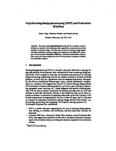
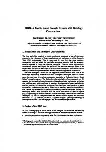
Figure 1. Points: reaction cross sections available in literature (5), lines: cross sections calculated by ALICE91 code. Due to the high linear energy transfer (LET) values of (-particles, (-emitters are attracting the attention as superior agents for endoradiotherapy (1). 149Tb (t1/2 = 4.1 h, 76.2 % EC, 16.7 % α, 7.1 % β+, Ea = 3.97 MeV) is reported to be a potential radionuclide for targeted cancer therapy with an efficacy of 100 times that of 131I for killing isolated cancer cells (2-4). This radionuclide can be produced by high energy proton induced spallation in a tantalum target followed by on-line isotope separation (4), or more conveniently by heavy ion nuclear reactions using cyclotrons. The most promising production route seems to be the reaction 141Pr(12C,4n)149Tb since praseodymium is a single isotopic element, therefore it is a cheap target material. However, the yield of this reaction is not yet measured in the full energy range of interest, therefore we performed a numerical calculation using the ALICE91 code. The calculated excitation functions of the reactions 141Pr(12C,xn) are presented in figure 1 compared to the few measured cross sections (5). The calculated values are in good agreement with the experimental results, thus one can safely use the calculated excitation functions to estimate the practical yields of these reactions in order to make a feasibility study for routine production via this production route.
10
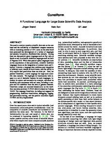
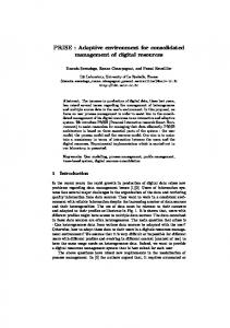
Figure 2. Saturated yields of the 141Pr(12C,xn) reaction for targets of different thickness (indicated by numbers in figure, in MeV).
Figure 2 presents the calculated thin target yields at saturation for different target thickness. It is obvious that the yields of the impurities 148Tb (t1/2 = 1.0 h, 48.62 % EC, 51.38 % β+) and 150Tb (t1/2 = 3.48 h, 70 % EC, 0.0007 % α, 30 % β+) are comparable to the yields of 149Tb, therefore a reasonable yield of 149Tb cannot be achieved without significant contamination by these radionuclides. Both of these impurities are decaying to long lived daughters, thus they will not influence the patient dose significantly. On the other hand, they are positron emitters with relatively high branching ratio, which could be utilized for in-vivo biodistribution studies of terbium labeled compounds by PET. Consequently, the simultaneous production of these three radionuclides must not be considered as a drawback. The VINCY Cyclotron of the TESLA Accelerator Installation will be capable for accelerating 12C3+ ions extracted from the ECR ion source in the energy region from 5.1 to 8.8 MeV/nucleon (61.2-105.6 MeV) which perfectly covers the range with the highest 149Tb yield. The ECR source can routinely deliver 300 (A of 12C3+ ions in a stable regime. It is expected that 60 % of this beam can be transported through the cyclotron’s spiral inflector and that 40 % of this bunched beam can be accepted by the RF system. Using the carbon stripping foil extraction system, one can extract a 12C6+ beam exceeding 95 % efficacy. Finally, around 80 % of the extracted beam can be expected on target in the solid target station of the Channel for production of radioisotopes (6). Consequently, one can calculate with a beam of 100 (A of 12C6+ ions on target. Assuming a realistic production schedule, one can optimize the irradiation conditions in order to obtain maximum yields and radionuclide purity at the application time. Such an optimization was made for the following parameters: 8 h irradiation time (which results in 75 % of saturated yield of 149Tb), 100 (A of 12 6+ C beam on target, 30 min. for transport of the target to the hot laboratory, 2 h for target processing and labeling, 30 % losses in chemical processing, 2 h for transport to the hospital.
11
Table 1. Calculated yields and radionuclide composition of labeled compounds available in the hospital at the time of application, for different target thickness.
target thickness, MeV optimal impact energy, MeV
2.5 74.3
5.0 76.0
7.5 77.6
10.0 78.9
15.0 81.7
20.0 84.9
30.0 92.1
0.00 0.09 5.10 0.31 0.01 5.50
0.00 0.23 9.90 0.61 0.02 10.76
0.00 0.42 14.49 0.93 0.03 15.87
0.00 0.62 19.00 1.34 0.04 21.00
0.03 1.13 26.84 2.22 0.06 30.28
0.21 1.90 32.88 3.21 0.07 38.27
1.95 3.60 40.03 5.47 0.11 51.16
Tb Tb
0.0 1.6
0.0 2.1
0.0 2.7
0.0 2.9
0.1 3.7
0.6 5.0
3.8 7.0
Tb Tb 151 Tb
92.6 5.6 0.2
92.0 5.7 0.2
91.3 5.9 0.2
90.5 6.4 0.2
88.6 7.3 0.2
85.9 8.4 0.2
78.2 10.7 0.2
147
Tb Tb 149 Tb 150 Tb 151 Tb 148
yield, mCi
total activity, mCi 147
radionuclide purity, %
148 149
150
The optimal impact energy resulting in maximum radionuclide purity of the product for different target thickness is listed in table 1. As one can see, the available activities at the application time produced in a single batch are suitable for clinical studies on several patients, which justifies the expectation that 149Tb can be efficiently produced at the TESLA Accelerator Installation for experimental purposes. References 1. Stöcklin G., Qaim S.M., Rösch F. Radiochim. Acta 70/71: 249 (1995)
12
2.
Goozee G., Allen B., Iman S., Sarkar S., Leigh J. Tandem accelerator production of Tb-149 for targeted cancer therapy. 18. AINSE radiation chemistry conference, 15. AINSE radiation biology conference, 3. national workshop on experimental radiation oncology. Lucas Heights, Australia, Nov. 10-12, 1996, Conference handbook, p. 60
3.
Allen B.J., Beyer G.J., Morel C.H., Aleksandrova Y, Jahn S. In vivo radiochemical properties of Tb-149: A new radiolanthanide for targeted cancer therapy., 18. AINSE radiation chemistry conference, 15. AINSE radiation biology conference, 3. national workshop on experimental radiation oncology. Lucas Heights, Australia, Nov. 10-12, 1996, Conference handbook, p. 62
4.
Beyer G.J., Offord R., Allen B.J., Groozee G., Imam S., Sarkar S., Leigh J. Targeted cancer therapy: The potential role of terbium-149. 6th International Conference on Radiopharmaceutical Dosimetry, Gatlington, Tenn. (USA), May 7-10, 1996, CERN-PPE/96-127
5.
Kossakowski R., Jastrzebski J., Rymuza P., Skulski W. Phys. Rev. C 32: 1612 (1985)
6.
Dobrosavljevic` A., Draganic` I., Vinc`a Institute of Nuclear Sciences, Laboratory of Physics, private communication
DEVELOPMENTS AT EBCO Karl Erdman, EBCO Technologies, Inc., 7851 Alderbridge Way, Richmond, BC V6X 2A4 Canada During the commissioning of the Sherbrooke TR19 cyclotron a variable energy extraction system for beams between 13 and 19 MeV was commissioned and simultaneous extraction of beams of 50 microamps into two target changers was achieved. Several new Fluorine targets were tested, the most novel utilizing an unpressurized, tilted, Titanium target body with a volume of 0.5 ml capable of supporting a beam current of 45 microamps. Along with a description of the operation of the cyclotron will be a description of the latest features of the chemistry systems under development. Discussion: Lewis Carroll: That last picture, are those going to get copper plated? Karl Erdman: What you saw, those are stainless steel sheets. The coils are laminated between two stainless steel sheets so they are sealed off. There is a copper layer, 1 millimeter thick, on top of those stainless steel sheets. John Clark: Could you just briefly comment on the principal of your methyltriflate system? Karl Erdman: The EBCO methyltriflate system starts off with 11CO2, which is then converted to methane by the usual process of high temperature catalyzation with hydrogen. The radio-methane is then passed through an oven and is converted to methylbromide by a recirculation process, which takes about three minutes at very high temperatures with very high efficiency, and then the methylbromide is converted over into the triflate. Jeanne Link: Karl, can you tell what the square area on your water target is? I know you have taken advantage of the angle to reduce a real heat load. Karl Erdman: The surface area of the target is about 2.5 cm2, that is the surface of the window, but the width is only 10 millimeters and it’s at a 30o angle of the beam.
13
A SUMMARY OF TCA DEVELOPMENTS SINCE PLACED IN SERVICE AT WASHINGTON UNIVERSITY G.G. Gaehle and M.J. Welch., Washington University Medical Center, St. Louis, MO
The Tandem Cascade Accelerator (TCA) installed at Washington University Medical Center in July of 1993 is a 3.7 MeV electrostatic linear accelerator capable of beam currents up to 1000 mA. Since December of 1993 the Tandem Cascade Accelerator has supplied O-15 radiopharmaceuticals to the Mallinckrodt East Building Imaging Center’s PET suite. Imaging is performed using a Siemens ECAT 953B scanner located directly above the TCA. During the past five years we have experimented with a variety of target designs and investigated improved O-15 radiopharmaceutical production systems. Modifications to the TCA and the accompanying production systems have been necessitated by the desire to increase the TCA workload to support another PET suite located in Barnes Neuro-Intensive Care Unit (NICU). The NICU PET suite is approximately 2500 feet away from the TCA. The control of the TCA from remote personal computers is accomplished using a software package from Symantec, PCAnywhere. Recent modifications to the TCA were implemented to increase the reliability of the terminal voltage operating at energies above 3.2 MeV, thus enabling the TCA to produce sufficient quantities O-15 radiopharmaceuticals to send to the NICU. The control system of the TCA is currently being operated in Windows 98/NT environment to allow easier and more reliable networking, in conjunction with the implementation of current documentation and management software. The delivery and production systems of the TCA are in the process of being upgraded to allow the delivery of O-15 radiopharmaceuticals to the NICU. The control of the new O-15 production system will be accomplished using a AT-MIO-16DE-10 board and Labview control software from National Instruments. The upgrade to the O-15 production system should be completed by the fall of 1999. Discussion: Lewis Carroll: I am not sure you know but there are resistors that are rated for high sparks or high joule discharge that are made by carborundum. I don’t know what you’re using but maybe you might want to contact those folks. Greg Gaehle: Yes, I will look into that. We are using carbon composite resistors that are encapsulated with epoxy. Lewis Carroll: Yes, but the carbon composites will fail after a number of sparks. John Clark: How many hours does this machine run for providing oxygen-15 per year? Greg Gaehle: At the moment, the actual run time is only two minutes on target so probably at the most about 30 minutes a week. John Clark: 30 minutes a week? Bruce what is your balance on your Cyclone machine? Bruce Mackay: We are running about 1,000 hours per year and window changes are about every 400 hours as a maintenance schedule. For activity, we are running beam currents up to 50 microamps at just under 4 MeV, very similar to your machine. The window is about 7.5 micron of titanium. John Clark: That is the Cyclone-3 which was coming on stream at the same time as work on all these other accelerators began, but there are three Cyclones out there in the field that are slugging away. Michael J. Welch: It is worth pointing out that our oxygen use has actually plummeted since all the brain activation people have gone to magnetic resonance imaging. But one of the advantages of this machine is that we have PET in the neuro ICU where we get people called in and it is much easier for the PET technicians to operate than the cyclotron. 14
Robert Dahl: You said you had some problems with the copper grid support but you didn’t say exactly what they were. Would you amplify on that? Greg Gaehle: We use the same target to make all of the oxygen-15 radiopharmaceuticals and there was an oxide layer being developed on the copper target that was causing it to fail. At least the yields were plummeting after two weeks of operation. Robert Dahl: All right, but you weren’t having any structural problems with the grid? Greg Gaehle: No structural problems at all.
15
PROGRESS REPORT ON THE DEVELOPMENT OF A FLUORINE-18 PRODUCTION TARGET FOR THE ACCSYS PULSAR(tm) SYSTEM. R. Hamm and G. Robinson, Jr.. AccSys Technology, Inc., Pleasanton. CA Presented by David Schlyer (Brookhaven National Laboratory). Work at AccSys Technology, Inc. in 1997 used the proton beam from the first AccSys Model PL-7i linac to demonstrate fluorine-18 production using an early R&D prototype target. The pulsed linac beam was used at low beam current (3-4 µA) with low enrichment (1%) oxygen- 18 water in the target. The beam current was limited by the duty factor of this particular low beam repetition rate system. The most recent series of target tests in 1998 used a higher beam current (5-15 µA) and higher enrichment oxygen-l8 water (2-8%) in an effort to define the conditions under which the final engineering prototype target will function reliably. The effects of various modes of irradiation (e.g., beam current, length of irradiation, target pressure, beam pulse structure, etc.) on fluorine-18 production were measured used the Model PL-7i system being built for Hitachi Ltd. of Japan for the Tsukuba Medical Center proton therapy project. A temporary beam line was installed on this system for these tests, and resulted in less than ideal beam optics.
Discussion: Ken Krohn: So do the AccSys people feel like they can get this homogeneity of the beam worked out? I think that is a serious concern for the RFQ’s. We had expected that the beam would be very homogeneous and stable but it just wasn’t. I’m curious as to whether that is going to be a problem with this machine. When you focus the beam down it looks stable but when you blow it up and really examine it, it’s just not very homogeneous. David Schlyer: Right, I think what we have done on the little one, the 4-MeV at Brookhaven, will answer your question. We have put a multiwire scanner on there and when you do that you can see a better distribution of the beam but it takes a fair amount of focusing and as you mentioned, the characteristics of the accelerator change as you change the fields. There is no question that it alters the shape of the beam, so the RFQ has to be in a final stable configuration before you can do the irradiation and expect to have a uniform beam. I think with the right focusing and quadrapole and steering magnets you can get a uniform beam, but it is not easy, and it has to be monitored during the irradiation. I think that is the take home message of what we have seen so far. You really need to look at the beam from time to time during the irradiation to make sure that you are not fooling yourself and getting into a tight spot. John Clark: Dave, just a quick query. The grid dimensions, did you quote the dimensions? I’m always worried about how much beam current do you dump on these grids, what fraction of transparency do you aim for? David Schlyer: These were all at 55% transmission, so we are knocking 45% of the beam off on the grid. That is just the way these were designed.
16
SUMMARY REPORT ON EVALUATION OF THE 10.5 MEV 3HE RFQ ACCELERATOR Kenneth A. Krohn1, Jeanne M. Link1, Phillip E. Young2, Richard DeHaas2, Delbert J. Larson2, and Ralph J. Pasquinelli3. 1University of Washington, Seattle, WA 98195-6004. 2Science Applications International Corp., San Diego, CA 92121 3Fermi National Accelerator Lab, Batavia, IL 60510 A 3He linear accelerator for radionuclide production has been discussed at recent WTTC meetings (1,2). The accelerating structure uses radiofrequency quadrupoles (RFQ) and was initially proposed as a collaboration between SAIC and UW in 1990 (3), but was extended in 1995 to include Fermilab and BRF. The rationale for developing a new 3He accelerator was to reduce the dependency on enriched target isotopes (especially 18
O) and to take advantage of lower neutron yields from neutron-deficient 3He. RFQs were expected to be simple to operate, have better power efficiency than cyclotrons, and require less shielding than a cyclotron. Engineering The RFQ accelerator has been described (4) and included a 3He+ ion source, a 212 MHz RFQ to accelerate 3 He+ to 1 MeV, a medium energy beam transport (MEBT) which included a charge doubler to 3He++, and three 425 MHz RFQs to raise the energy to 10.5 MeV. The research goals included constructing and evaluating targets capable of withstanding the power from the pulsed beam and using this beam to study target chemistry. As nucleogenic atoms lose energy in a target, they gain electrons and eventually undergo chemical reactions to produce stable molecular forms. These in-target reactions are radiation dose dependent under the high dE/dx of 3He. The precedence for producing the desired chemical form of positron radionuclides with continuous cyclotron beams might not hold for pulsed beams from the RFQ, where the instantaneous current density in the target is about 40-fold higher. Recoverable yields for the principal PET radionuclides (18F, 11C, 13N, and 15O) have been measured (5), as well as yields of some longer lived radionuclides. The 3He RFQ was equipped with extensive beam diagnostics, including wire profile monitors, Faraday apertures and cups, and current integrators biased for e- suppression. Ion chambers and Bonner spheres were used to measure radiation from the accelerator and targets. This information was datalogged. The RFQ only achieved about 30% of its designed beam current, but that was enough to provide an opportunity to test several important aspects of the pulsed 3He beam. The engineering aspects of the RFQ and the high energy beam transport system were recently reported (4). The HEBT was designed with magnets to spread the beam current profile and reduce current density to values close to cyclotron beams. The beam was designed to be Gaussian in the horizontal axis (2.3 cm wide) but at constant intensity in the vertical axis (10.5 cm long). We used thin target windows, 7.6 µm Arnavar alloy, with curved (2 cm radius) or flat foils retained by two O-rings. For most experiments, the window was unsupported across its 24 cm2 area. In some experiments, the window was supported by a long axis grid consisting of two 1 mm wide x 6 mm deep stainless steel pieces to divide it into three rectangles of 7 x 105 mm each. Calculations predicted that the strength of the window would increase 3x with use of the simple grid, and that improvement was verified experimentally; transmission measured by irradiating a graphite foil with the grid was 90% of the ungridded value. 3He RFQ targetry was different from a cyclotron, mostly due to beam quality. While targets could be cooled by spreading the beam area, the variation in beam intensity due to sparking created intense local hot spots which were difficult to cool and reduced window lifetime and target yields. Excessive sparking may have been a problem unique to this RFQ because of the closeness of the vanes.
17
Radionuclide Production Our recovered yields for the CNOF radionuclides used in PET have been reported (5) and are only tabulated here in summary form. The yields are for the 10.5 MeV 3He beam from the RFQ and are for thick targets covered with 7.6 µm Arnavar windows. We typically irradiated long enough to achieve equilibrium yields for the CNO radionuclides and for two hours for F. The yields in Table 1 are reported as equilibrium values and are normalized to a beam current of 100 µAe. Table 1. Production of CNOF Radionuclides Using 10.5 MeV 3He. Nuclear Reaction Target 12C(3He,4He)11C graphite 10B(3He,pn)11C B2O3 10B(3He,pn)11C B 9Be(3He,n) 11C beryllium 12C (3He,pn)13N graphite 14N(3He,4He)13N N2 16O(3He,4He)15O water 16O(3He,4He)15O O2 14N(3He,pn)15O N2 16O (3He,p) 18F water * Equilibrium yields at 100 µAe
GBq* 50 10 37 16 6.3 1.9 0.43 (O15O) 17 11 15 (2 hr irrad.)
In order to extend the use of the RFQ beyond CNOF radionuclides, we irradiated other materials, including metals with atomic numbers above the classical Coulomb barrier for 10.5 MeV 3He++, Z =22. Targets included Zn (99.9%. 0.127 mm), Fe (99.9%, 0.1 mm), Co (99.95%, 0.05 mm), Ni (99.9%, 0.1 mm), and Cu (99.98%, 0.1 mm) from Aldrich Chemical Co. There are several nuclei in this region that are useful for nuclear medicine. The targets were the pure elements at their natural abundance. Irradiated foils were analyzed by decay curve analysis and gamma spectrometry using HPGe detectors at FNAL. The results are shown in Table 2. Table 2. Production of Metal Radionuclides Using 10.5 MeV 3He. Target *
Products**
Iron- 56, 54, 57, 58 Cobalt- 59 Nickel- 58, 60, 62, 61, 64 Copper- 63, 65 Zinc- 64, 66, 68, 67, 70 * in order of natural abundance
53
Fe, 55Co, 52Fe, 56Ni 60 Cu, 61Cu 59 Cu, 60Cu, 62Cu, 60Zn, 61Cu, 62Zn, 57Ni, 56Ni 62 Cu, 61Cu, 64Cu 63 Zn, 65Ga, 66Ga, 67Ga ** in order of yield (MBq/µA at saturation)
For the most part these reactions would give low specific activity products and are not useful for routine production, but the Ni target as a route to some useful Cu radionuclides may be worth further evaluation. For each of the metal targets, the (3He,pn) product yields (in units of atoms, not activity) dominated, followed closely by the (3He,p) products. Both (3He,❏) and (3He,n) yields were lower by as much as an order of magnitude. These results emphasize the modest binding energy of the 3He nucleus (2.6 MeV/nucleon) compared to the alpha particle (7.1), and the role of stripping reactions for 3He at higher Z. 18
Radiation Measurements The RFQ vanes and vacuum housings were constructed from aluminum and yielded x-rays at >0.1 Gy/hr, but this was eliminated by using 0.75” thick stainless steel vacuum tanks. Neutron and gamma ray production from the RFQ was also significant. The largest radiation fields exceeded 1 mSv/hr at 100 µAe and were principally due to particle losses at the small apertures between the RFQ tanks. The initial proposal for the RFQ had anticipated that the modest neutron yields associated with 3He nuclear reactions would be an important advantage in siting an RFQ in a hospital. A factor of at least tenfold fewer neutrons than from proton or deuteron reactions was anticipated. The yields of neutrons have been measured and are reported in Table 3. These yields were measured using a Bonner sphere axial with the RFQ beam and at 50o. The neutron flux off axis was the same as the axial yield, except for C and Be, where forward scattering was favored by about 1.5-fold. The neutron yields ranged from 0.9 to 1.1x10⁸ neutrons/µcoul, lower than for 2H reactions but only a modest advantage over 1H. The neutron yields were sufficiently high from Be to convince us to abandon this route for 11C. The neutron yields from irradiation of Al were also high, making this material not useful for building targets or parts of the HEBT that might be struck by stray beam. The neutron yields on stainless steel reflect the rate of breakup of the 3He nucleus.
Table 3. Neutron production from 3He irradiation. Target carbon
neutrons/s/µA 1.01 (±0.14) x 108
nitrogen oxygen water beryllium boron aluminum
1.13 (±0.06) x 108 0.91 (±0.06) x 108 0.85 (±0.12) x 108 9.75 (±0.8) x 108 1.27 (±0.5) x 108 3.26 (±0.39) x 108
stainless steel
0.57 (±0.38) x 108
Conclusions Target yields of the PET radionuclides were near those predicted, but machine radiation was somewhat higher than anticipated. Production yields at 100 µAe were only marginal for PET, but if the accelerator had achieved the design goal of 200 µAe, yields would have been sufficient for clinical work. The high radiation of the pulse gave chemical forms of the radionuclides only slightly different from a continuous beam, although radiolysis products were detected in the water target and also in the O2 and N2 gas targets. Overall, the RFQ did not give the benefits that were anticipated. The accelerator was difficult to operate and did not achieve the anticipated beam distribution profile or output current. However, the radiochemical yields were as expected given the final energy and current. Our experiments were done at a current density of about 500 µA/cm2 on the target window during each pulse, and so these results may be useful to others investigating pulsed linear accelerators for PET. The 3He++ RFQ at Fermilab has ceased operation and the accelerator has been decommissioned. This research was supported by USDOE. 19
References 1. Krohn, K.A., Link, J.M., Weitkamp, W.G., et. al. “3He RFQ for PET Isotope Production. A UW/SAIC progress report,” proceedings of the Fifth International Workshop on Targetry and Target Chemistry (J.R. Dahl, ed.), Brookhaven, September 1993, pp. 20-29. 2.
Krohn, K.A., Link, J.M., Young, P., et. al. “3He RFQ for PET Isotope Production. A brief progress report, August 1995,” proceedings of the Sixth Workshop on Targetry and Target Chemistry (J.M. Link and T.J. Ruth, eds.), TRIUMF, Vancouver, BC, August 1995, pp. 38-39.
3.
Dabiri, A.E., Hagan, W.K., Swenson, D.A., and Krohn, K.A. “A 3He++ Radiofrequency Quadrupole Accelerator for Positron Emission Tomography,” Nuclear Technol. 92: 127-133, 1990.
4.
Pasquinelli, R., “A 3He++ RFQ Accelerator for Production of PET Isotopes,” presented at the Particle Accelerator Conference, Vancouver, BC, May 1997.
5.
Link, J.M., Krohn, K.A., Bida, J.T., et. al. “Production of PET Radionuclides Using a 10.5 MeV 3He RFQ Accelerator,” proceedings of the Sixteenth International Conference on Application of Accelerators in Research and Industry, Denton, TX, 1998, Am. Inst. Phys. Conf. Proceedings CP475 (1999), pp. 1010-1012.
Discussion: Lewis Carroll: Where did all of the neutrons come from? Ken Krohn: Well if you actually look at the physics of the 3He, the binding energy per nucleon in 3He is totally different from the alpha particle. It is pretty lousy, in fact. So 3He is sort of a bag of 3 particles that are kind of traveling in a loosely associated way and in the nuclear reaction you get serious break up of the 3
He. However, the radiation that we saw was mostly because the apertures between these tanks were small enough that we lost a significant fraction of beam at each aperture between tanks. The small aperture wasn’t chosen for physics reasons, it was because they were afraid the chemists were going to break targets and fill their machines with water, which we never really do. Karl Erdman: Would you still regard 3He as a good way to go for the production of isotopes if you could lick the problems? Ken Krohn: I would regard any accelerator that was turn key off the shelf that I didn’t have to fight with each morning, as a good way to go to make isotopes.
20
ISOTOPE PRODUCTION AT INTERNATIONAL ISOTOPES, INC. I.L. Morgan, Homer Hupf, Gaylord King, John Armbruster; International Isotopes, Inc.; Denton, TX In this day of increasing demand for Radiopharmaceuticals and Radioisotopes, there is a need for a source of bulk material for contract manufacture. International Isotopes, Inc plans to fill this need with its 70 MeV 1000 µA LINAC, its CP-42 Cyclotron and the Reactor Services at Idaho. The LINAC can deliver beams on target at 70 MeV, 50 MeV, and 30 MeV energies for optimal isotope production to any of its six target stations. Upon completion of the irradiation, the targets are pneumatically transferred to the Chemical Processing area were the Radioisotopes are separated and purified into their final form in specifically engineered hot cell. The now pure bulk Radioisotope can then be shipped to the customer or transferred to our state of the art Radiopharmaceutical Manufacturing Facility and turned into a finished Pharmaceutical product. The variable energy aspect of the CP-42 cyclotron is ideally suited for research into the production of new clinical isotopes.
Discussion: Jeanne Link: I saw your facilities during the Denton Meeting and at the time they were incomplete. I realize that you work more with the cyclotron than the linac, but at the time they were talking about not shielding those targets, which consist of six stations right next to each other. You said that they are doing target shielding; have they decided they needed to shield them? John Armbruster: Yes, all the targets are going to be self-shielding or to have removable shielding around the targets from the radiation safety standpoint. Jeanne Link: One other question. How much current are you expecting now that you have been testing the linac? What amount of current are you obtaining of the linac coming through the drift tubes? John Armbruster: I’m not really sure. The gentleman that is in charge of that didn’t really say. I don’t know what the exact current number is but they have run 33MeV beams through the 150 ft. drift tubes. John Clark: Interestingly decommissioning cyclotrons is becoming quite expensive to actually be able to pass it on to somebody else is a way of avoiding that. Congratulations on reusing the CP-42. There are three or four sites exchanging machines around at the world at the moment, I think Lewis Caroll has a list of them.
21
A SECOND TARGET STATION FOR THE BOMBARDMENT OFSEMI-PERMANENT TARGETS AT THE NAC. F.M. Nortier1, P.J. Binns1, J. Hanekom1, M.A. Penny1, R.E. Quantrill1, HA. Smit1, T.J. van Rooyen1 and V.M.P. Xulubana2. 1National Accelerator Centre, P.0- Box 72, Faure 7131, South Africa. 2University of Western Cape, Private Bag XI 7, BellviIle 7535, South Africa Radioisotopes for medical and industrial use are produced at the NAC with a 66 MeV proton beam, which is shared with the NAC’s neutron therapy programme. Production targets are bombarded regularly during the week nights from Monday to Thursday. In addition to these allocated shifts of 8 hours each idle beam during the neutron therapy sessions resulting from the various patient set up procedures is also utilised for radioisotope production. Only one shielded bombardment station1, suitable for batch-type productions, was available for this purpose during the past 10 years of operation. Recently a second shielded target station for the bombardment of semi-permanent targets was designed and installed. This addition allows the bombardment of targets requiring services such as gas and liquid connections at high beam currents without the danger of excessive neutron activation and radiation damage to sensitive components in the vault. The new target station enables much larger quantities of 18F to be produced with our Ne-gas target system2. This presentation outlines the main design features of the rotary target magazine and its neutron shield and describes how the assembly interfaces with the beam line. In order to determine the effectiveness of the neutron shield a Bonner Multisphere Spectrometer was used to measure the neutron fluence spectra in the vault during the proton beam bombardment of a copper target. References 1. S.J. Mills, F.M. Nortier, W.L. Rautenbach, H.A. Smit and G.F. Steyn, A multi-purpose target station for radioisotope production, Proc. 12th Int Conf on Cyclotrons and their Applications, Berlin, 1989, eds B. 2.
Martin and K. Ziegler (World Scientific, Singapore, 1991) p.527. F.M. Nortier, F.J Haasbroek, LH Langenhoven and F. Vorster, Neon gas target and synthesis system for the the production of 2-[18F]fluoro-2-deoxy-D-glucose with a 66 MeV proton beam. Proc. 6th International Workshop on Targetry and Target Chemistry, Vancouver, Canada, 1995, eds. J.M. Link and TI Ruth. (TRIUMF Publications Office 1996) p.68.
Discussion: Syed Qaim: Just a question as to the neutron measurements. If I can see from the picture, they begin about 1 MeV and you have gone up to about 10 MeV. Have still higher energy neutrons not been looked for, or they so low in intensity that one doesn’t see them? Francois Nortier: No, unfortunately we depend on a Bonner sphere spectrometer that makes use of the different polyethylene spheres to moderate the high-energy neutrons. We had spheres only up to a quarter of a meter. That means we can measure only up to about 10 MeV. So basically the measurement system was blind for higher energy.
22
MINITRACE(tm) TRACER PRODUCTION SYSTEM S91 20JL (WORK IN PROGRESS) Martin Orbe GE Medical Systems - Americas: Milwaukee. Wisconsin, USA Fax: 414-5484486 GEMSEUROPE-Paris. France Fax: 334-30704639 GEMS-A SIA - Singapore Fax: 65-221 7008 YMS, Tokyo, Japan - Fax: 81-425855490
Dual lrradiation Capability To further enhance the utility, the MINItrace can be equipped with an optional dual beam extraction system that allows simultaneous production of two radionuclides. This feature can be especially attractive for a user who wants to produce larger quantities of 8F/FDG for distribution.
Application The GE MINItrace(tm) Radio Tracer Production System is a very compact, fully radiation shielded and highly automated cyclotron-based system- It is specially designed for inexpensive, easy and efficient production of the most common PET tracers.
Features The MINItrace system is based on the successful, well-proven design of the PETtrace concept but it is even simpler and more user friendly This has resulted in an extremely reliable and affordable system overall.
The MINItrace System
Novel Cyclotron
Compact Installation
The MINItrace is based on a compact negative ion cyclotron of novel design. The cyclotron features a vertical midplane and accelerates protons to 10 MeV. The MINItrace can in a very flexible way be configured with targets for production of all common PET radionuclides. The negative ion technology provides enhanced extraction efficiency
Most peripheral systems are integrated with the radiation shield. This makes the MINItrace the most compact PET tracer production system available, for production of the common PETtracers.
with minimized buildup of internal radioactivity.
Easy to use The MINItrace is fully automated from start-up to delivery of the final tracer. No advanced training is required for normal operation of the system.
Integrated Radiation Shield The MINItrace contains an integrated radiation shield. The shield reduces the total radiation level allowing operation in a standard room- The shield also houses a storage line for waste gas decay (patent pending).
23
System Components (P5220JE) MINItrace cyclotron with the following sub-systems: magnet, Ion source. Rf-system, extraction. vacuum. diagnostic. closed loop cooling, control system and radiation shield. (P5230JN) Fluorine-18 Target System for production of 18F as fluoride. (P5230JP) Nitrogen-l3 Target System for in-target production of 13N-ammonia
Accessories for the MINItrace System (P9l20JF-JJ) FDG MicroLab, a compact, computer controlled automated system which efficiently converts fluoride into 18F-labeled FDG. This chemical processing unit is reliable and efficient and incorporates a unique disposable cassette technology for easy preparation of high quality FDG.
System Performance Radiochemical
Yield
18
>1000 mCi > 75 mCi
F-HF13 N-NH3
Additional data Dimensions: 3.5x2.05x2.lO (w*d*h) m Weight: ~ 45,000 kg Power consumption: 30kW (operation) 35kW (standby) Electrical requirement: 35 kVA. 3-phase, 50-60 Hz Minimum recommended room size: 5.5 x 4.5 m The system is Y2K compatible Warranty The General Electric Company provides specific warranties with respect to the products described. The applicable written warranties for these products are available upon request. Rights are reserved to make changes. Note: The information contained in this publication is subject to change without notice. Discussion: Raisa Krasikova: Which material do you use for construction of the nitrogen target and which method do you use for [13N]NH3 production? Martin Orbe: We use in target production by [16O]water with methane gas over pressure.
System Operation The MINItrace system is operated through a workstation The user interacts with the menu driven control system in a windows environment by using the keyboard and mouse. A database provides logging and long-term storage of all production and system parameters and each production is summarized in a printed and stored production report, supporting GMP requirements.
24
THE NEW ISAC FACILITY AT TRIUMF. Thomas J. Ruth, TRIUMF, Vancouver, Canada TRIUMF, Canada’s National Lab for nuclear and particle physics has just finished a new radioactive ion beam facility designed to produce a variety of nuclei far from stability by bombarding a thick target with 500 MeV protons at 100 µA followed by mass separation of the desired species. There are 2 experimental areas, one that uses the 60 keV ions isolated by the mass separator and the other will make use of the 0.15 to 1.5 MeV/u post accelerated beam. For post acceleration, singly charged ions of up to mass 30 having an energy of 2 keV/u will be accelerated in a two stage linac consisting of an RFQ and a post-stripper drift tube linac up to 1.5 MeV/u. In order to preserve beam intensity CW operation is required. The main features of this accelerator are: 35 MHz RFQ, stripping at 150 keV/u beam energy continuously variable from 0.15 to 1.5 MeV/u and CW operation. Commissioning and preliminary results will be presented.
Discussion John Clark: Tom, I realize this could be the subject to another complete morning session, but could you just outline the general principles of releasing the primary isotope from your target, you just showed alkali metals which are obviously the easy ones. Tom Ruth: What you try to do is operate at very high temperature, you do spallation and there is some recoil, but most of it is simply thermomigration through the materials. You can either use surface ionization or ECR for the ion source and then, once you have the ion, you accelerate it, with the extraction system, into the separating magnets. But it is primarily a physical mechanism of having hot targets that will release these materials. Obviously TRIUMF is starting with fairly simple materials. Some of the principles that Ken talked about could be used as well, where you use stacked systems and can have fairly easy recoil release then use sweep gases to take the reaction products out of the target. Most of these will be physical phenomena for getting out the elemental particles. Tim Tewson: What sort of efficiency do they get from production in the target to getting the particles through the separator and down to the end of the beamline? Tom Ruth: The real issue is getting the particles out of the ion source. The extraction efficiency of an ECR source is typically, depending upon the element, on the order of 10%, sometimes less, but 10% is what you aim for. Surface ion sources have a bit higher efficiencies, they can be as high as 30%-40%. Ken Krohn: It is nice to see a successful RFQ, Tom, thank you. 1.5 MeV per nucleon is just right for an RFQ, which is where you are. My real question is, what is a continuous pulse beam from an RFQ? Tom Ruth: It is not a continuous pulse beam. The RFQ operates at continuous wave and they have a buncher which bunches the beam at the time schedule that you want. Ken Krohn: So what sort of time range of the pulsing is available to you? Tom Ruth: I’m not sure, but they can make it smaller than the eighty six nanosecond pulsing that they now use. That was designed to match the oxygen-15 experiment that they intend to study. I may not have shown it clearly enough. After the RFQ goes through the DTL the DTL can operate at any one of the combination of the tanks to give you continuous available 0.15 to 1.5 MeV per nucleon to the station. The ISAC II is proposed in the next funding period and that is to take the energy up to, I think, 10 MeV per nucleon, which opens up the range of possible nuclear physics experiments.
25
OVERVIEW OF ACCELERATOR DEVELOPMENT AT NSI Robert E. Klinkowstein, Ruth E. Shefer, and Barbara J. Hughey. Newton Scientific, Inc., 245 Bent Street, Cambridge, MA 02141 Newton Scientific, Inc. has developed a line of compact, continuous-current ion accelerators for medical and industrial applications. These machines are based on a highly efficient, high voltage switching power supply technology that can provide milliampere currents at voltages of up to several MeV. An overview of installed accelerator systems and new systems under construction will be presented. These include a 2 MV terminal tandem for neutron capture therapy, a 1.5 MeV biomedical proton microprobe, a 1 MV tandem for accelerator mass spectrometry of 14C- and 3H-labeled biological samples, and a 1.5 MeV deuteron accelerator for 13N production for materials analysis with positron beams. High power targets and radiochemical separation systems for cyclotron production of large quantities of intermediate-lived radionuclides are also under development.
Discussion: Tom Ruth: A couple of questions. Bob, I think I missed your mass range for the AMS. Robert Klinkowstein: There are really only two ions of interest for that particular machine; one is carbon-14 and the other is tritium. These are the only two and although it may be able to do some other masses in that range it does not go to very high mass numbers. Tom Ruth: And for the positron source, the nitrogen-13 stays in the target. Did you look at the carbon-13 proton reaction, because it has a much higher cross section? Ruth Shefer: It requires higher energies and the idea here was to build a really low energy laboratory scale machine. Ken Krohn: Do you have information on the spatial homogeneity and stability of the beam for this machine? Have you let it blow up to a big enough area that you can really map it with an activation experiment and tell us how stable and how uniform the beam is? Robert Klinkowstein: We have not done that, however, it has been a topic of discussion at MIT because of their desire to do detailed thermal analysis of their targets. The question is, what is their input power? How is it distributed? And they can’t do any simulations until they know it, so there certainly is a desire to do that. We have talked about doing autoradiography and that is on the list of things to do. The one thing we do every time we run is measure temperature on our targets, and Brandon can answer more questions about this than I can. Our targets are surrounded by thermocouples azimuthally so we measure the temperature as a function of angle just outside the beam strike as close as we can get to the beam strike but not in the beam strike. That turns out to be a very sensitive measure of whether the beam is centered. Is it moving around during an hour or two of irradiation? The information from the thermocouples says that the beam is very stable. We don’t see changes in time. We have the ability to focus the beam down to a millimeter. Another thing we have done is to aim a video camera on the target so we actually see the targets. We bring them all the way to melting and you can see ablating (metal coming off) and we can defocus the beam and completely control that situation, but we haven’t done an accurate measurement of the beam profile. Ken Krohn: That is a very good technique if you are very careful at electrically isolating the thermocouples. Syed Qaim: In the analysis with positrons, very commonly a sodium-22 source is also used. Could you give some comparison of the energy of positrons from sodium-22 as compared to the positron accelerator described here, some of the advantages and disadvantages? 26
Robert Klinkowstein: Actually Ruth knows more about this than I do but before she answers the question, in both of those cases, the positrons are moderated down to basically thermal energy so we don’t extract the positrons right off the carbon target. They are actually moderated by a variety of techniques, a tungsten moderator for instance. The positron energies are brought down to nearly thermal and then they are accelerated to the target. But the positrons that are produced by sodium-22 verses the nitrogen-13 technique have different energies. I don’t remember how they compare do you Ruth? Ruth Shefer: The energy of the sodium-22 positrons is about half that of the nitrogen-13 positrons and what that translates into is, for nitrogen-13 we have a somewhat lower efficiency of moderation in the moderator that we place after the targets. We compensate for that by making more activity so it really doesn’t effect the measurement.
THE FABULOUS FOX THEATRE: A major performing arts center and supreme example of grand movie places of the past.
27
COMPACT LINAC SYSTEMS FOR MEDICAL APPLICATIONS W. Joel Starling, Linac Systems, 2167 N. Highway 77, Waxahachie, TX 75165 Three compact linac systems for medical applications are under development at Linac Systems, based on the revolutionary Rf Focused Drift-tube (RFD) linac structure This new linac structure resembles a drift tube linac (DTL) with rf quadrupole (RFQ) focusing incorporated into each “drift tube”. It promises to yield, smaller, more efficient, and less expensive linac systems for a variety of scientific, medical, and industrial applications. A prototype of the RFD linac structure has been built and is currently under test. The targeted medical applications include Isotope Production for PET, Epithermal Neutron Production for BNCT, and an Energy Booster for Proton Therapy. The isotope production unit is based on a 12-MeV proton linac with an average beam current of 120 µA, which can be directed onto any of three targets simultaneously. The epithermal neutron source is based on a 2.5-MeV proton linac with an average beam current of 10 mA, which can be directed onto a solid lithium target. The proton therapy unit is designed to boost a small portion of proton beams, in the energy range of 10-20 MeV, to the required energies of 70 and 250 MeV. The status of these designs and their readiness for production will be presented. *Supported by the National Institute of Mental Health (NIMH) and the National Cancer Institute (NCI). Discussion: Tim Tewson: You claimed lower utility costs on your overhead for the PET accelerator. Now a problem that Ken (Krohn) didn’t mention with their RFQ was that when you turned it off it usually took ages to condition it as soon as you turned it back on again, days and days if I remember rightly. The result was that they had to leave the system running continuously and its power consumption was not modest. This led to essentially a very high utility cost. Do other RFQ’s have that same problem, or can they be turned on and off at will? Joel Starling: Well our RFQ can be turned off at will and it takes basically, the time it takes to pump down the system, several hours, then maybe several hours of conditioning for us to run the RFQ again. Now I honestly can’t answer your question for other accelerators, I’m not familiar with the experience that others have had. If anyone wants to comment that’s fine, but for our particular RFQ, we have not had difficulty with conditioning. We are able to run it on as a needed basis. Tim Tewson: But if several hours of conditioning are required, that means if you want to use it on a daily basis you have to leave it on all the time. Joel Starling: Okay, I may be incorrect on the several hours, I’m just remembering the experience we had running our RFQ to date and I would actually like to defer it to Don Swenson if you want to contact him for specific information about conditioning of the RFQ. David Schlyer: If I could just a comment on that Tim. On our RFQ, the one at Brookhaven, when you open it up to air then close it back up again, typically it has taken about two hours to bring it back into operation. However, if you leave it under vacuum pumping, it doesn’t take long, a few minutes to bring it back up to operational readiness. Joel Starling: Yes, I guess I was referring to opening it up to air and going through the vacuum pumping and the conditioning after you open it up to air, but that is a good point. Leaving it under vacuum helps with that situation.
28
IBA DEVELOPMENTS IN THE FIELD OF ACCELERATORS R.Verbruggen, F.Schmitz, M.Ghyoot, F.Vamecq, Y.Jongen. Ion Beam Applications, Chemin du Cyclotron 3, 1348 Louvain la Neuve, Belgium The aim of IBA is to develop products in the field of particle accelerators for the medical and industrial sectors. Since its creation in 1986, IBA has designed ten types of high performance accelerator.
IBA’s products are used in research, medicine and industry and has diversified in three main sectors: • medical imaging: radioisotopes used in nuclear medicine and positron emission tomography, •treatment of certain types of cancer by radiotherapy (protontherapy and brachytherapy), • industrial applications involving the projection of electrons, such as sterilisation of medical instruments, polymerisation of materials, pasteurisation of food. This paper presents the design and the successive improvements of these cyclotrons, since several units of each model are in operation on a regular basis for industrial, clinical and research purposes. Table 1 : Applications and basic characteristics of IBA cyclotrons. Designation energy (MeV)
Beam intensity (µA)
Typical beam
Unit sold production
Typical
Cyclone-3 Cyclone-10/5
3 d10 p-, 5 d-
80 100
4 4
15
Cyclone-18/9 Cyclone-18+ Cyclone-14+ Cyclone-30 Cyclone-235
18 p-, 9 d18 p+ 14 p+ 30 p235 p+
150 2000 2000 1000 1
17 14 2 17 4
O
15
O, 11C, 13N, 18F O, 11C, 13N, 18F, 124I 103 Pd 103 Pd 123 I, 201Tl, 67Ga, Protontherapy 15
Discussion: Ken Buckley: Can you say something about your stripper foils? You mentioned you have new ones. F. Schmitz: Yes, we have increased the thickness of the stripper foils in order to reduce the need to ventilate the machine to air. Ken Buckley: Do you remember what thickness they are? F. Schmitz: No, but I can send you the details of them. Ken Buckley: Are you making the stripper yourself? F. Schmitz: Yes we are making them ourselves. Nigel Stevenson: Can you tell us a little more about the self-extraction? You said it’s under development. F. Schmitz: No, I can’t. I’m working on the targetry and in all honesty I cannot explain to you what the calculation is that is run by our calculation department. The basic principle is to introduce the modification in the magnetic field on the extraction of radius at 18 MeV and bend the beam by this way out of the machine. But I cannot go into details, sorry! 29
THE MUNY: St. Louis’ answer for exciting outdoor musical theatre.
30
High Yield F-18 Production Organizers John C. Clark and Stefan K. Zeisler
31
INTRODUCTION TO THE HIGH YIELD F-18 PRODUCTION SESSION John Clark, Wolfson Brain Imaging Centre, University of Cambridge, UK As the world demand for 18F labelled PET radiopharmaceuticals, in particular (18F) FDG continues to grow; the development of cyclotron target systems capable of making effective use of the current cyclotrons proton beam capabilities is an essential endeavour. Most cyclotrons installed for dedicated PET applications are capable of delivering 50 - 100 µA of proton beam at 10 to 18 MeV depending on the type. Dual beam extraction is also possible on most machines so a target design goal would achieve good saturation yields at 50 µA. The key issues to be addressed in achieving success are as follows; 1.
Target body issues • Material • Chemically stable/passive. • Thermal conductivity. • No incompatible metal mixes! • Workable (machining/forming/electroplating).
32
2.
Window • Chemically stable/passive. • Strong at high pressures and temperatures. • Easily changed, maybe remotely (radiation dose to operator high).
3.
Seals for window and pipes • Chemically stable • Compatible with other materials in assembly
4.
Geometry • Cooling fins inside the target volume or outside in the cooling water flow. • Reflux region for evaporative cooling. • Self draining for H218O recovery.
5.
Water transfer pipes • Chemically stable. • Radiation resistant. • Non 19F containing. • Useable with easily available fittings and seals.
6.
Valves • Chemically stable. • High pressure rating. • Uses easily available fittings & seals. • Remote operation and position sensing. • Radiation resistant as the valves usually need to be mounted close to target to minimise dead volumes.
7.
Power dissipation • Power in equals Power out (cooling). • The poor thermal conductivity of water (heat transfer to the target body). • Boiling point of water versus Pressure. See Fig. 1 • Use of evaporative cooling (latent heat of evaporation).
8. Beam Quality issues • No “hot spots” • Optimal size versus window stresses • Theoretical yield versus Ep • Power dissipation versus ▲ ▲E (Bragg Peak) o If dump the Bragg Peak energy into target body will it affect its chemical properties? 9.
Figure 1
Water quality issues • New versus recycled? • Quality control criteria?
There are now several commercially available targets, which are in limited use and we have reports on two of them in this session. An ability to extend the performance to 100µA presents some interesting challenges. The use of an 18O2 gas target modelled on the commercially operated 123I productions at beam current in excess of 100µA is an interesting possibility as does the inclined high pressure reflux target that Karl Erdman describes. Some of the older cyclotron installations are seeking target upgrades. This has been achieved by either home redesign or by adapting a commercially produced target to fit the beam line characteristics. There are two such examples mention in the session disscussions. The production of [18F] F2 from 18O2 is now being used in the routine production of [18F] FDOPA in at least 6 centres and some further optimisation work as reported in this session. The availability of highly enriched 18O for these target systems has always been hostage to a fluctuating world demand. With the rapid growth in the demand for clinical [18F]FDG PET there is some risk of a shortfall in production capacity of 18O. The application of an effective recovery, purification and possibly re-enrichments process is timely. Some discussion of this issue provided some windows of opportunity for further exploration.
33
HIGH YIELD 0-18 WATER TARGET FOR F-18 PRODUCTION ON MC-17 CYCLOTRONS M.S. Berridge, K. W. Voelker, B.J. Bennington. Case Western Reserve University and University Hospitals of Cleveland, 11100 Euclid Ave. Cleveland, OH 44106 The MC-17 cyclotron (Scanditronix AB) was installed in university and hospital PET centers worldwide until the sale of the company in about 1993. The majority of those machines were supplied with a water target for F- 18 production that was made of silver in a double-foil keyhole design. (1 ;2) The targets were designed to meet the needs of PET facilities of the late 1980’s which engaged primarily in research with only a small, if any, clinical component. Conservation of 0-18 water while permitting the production of a few GBq, or a few hundred mCi, of F-18 fluoride was the primary goal. The target was therefore designed to be small. It accepted enough beam current to produce the necessary amount of fluoride, but used only half the beam that was produced by the cyclotron. That target met the design goals and has produced daily batches on the order of 20 GBq for routine synthetic use over the past ten years. However, the earlier slow and steady increase in clinical use of PET worldwide resulted in reasonable reimbursement for clinical studies which in turn has made hospitals much more willing to provide clinical PET. Combined with the appearance of positron-capable gamma and SPECT cameras, this has dramatically increased the demand for fluorine-IS from many of the MC-17 installations. Although the original silver target was sufficient for the demand of the time, it does not make full use of the ability of the cyclotron, and its production leaves something to be desired in a high-demand environment. It also requires maintenance at intervals of three to eight weeks mainly because of build-up in the target of silver oxidation products. In order to increase production capability and reduce the need for maintenance, a new target was designed and tested. This target has a different set of design criteria. Enriched water is no longer the severely limiting factor that it was through the late 1980’s. Effective recovery and recycling techniques combined with strong increases in supply capacity have removed it as a limiting factor in the operation of a PET facility. Water conservation is therefore no longer a stringent design goal. Production requirements have strongly increased. The demand for F-18 from a single PET seamier has increased five fold since the design of the earlier MC-17 targets. In addition, there is a strong possibility that each cyclotron will be supplying multiple PET and coincidence gamma cameras, multiple institutions, and transporting product some distance from the radiochemistry laboratory. Therefore this design was intended to maximize the production capacity of the target, and make the beam capacity of the cyclotron the limiting factor in production. The beam of the MC-17, most of which were installed without external beam lines or focusing optics, is about 3mm in height and 3 cm wide. It is not uniform intensity across the entire width, but tends to have ‘hot spots’ at the outside edge. The foil entrance must therefore be at least this large. The resulting foil area and beam density variations create a tendency for target foils to fail under high operating pressure. In the past (2), we have shown that a sufficient gas space above the target water allows the water to cavitate and reflux within the target under low pressure without ejecting water from the target and without loss of target yield. The previous silver design gave the produced fluoride good chemical reactivity, but required maintenance at intervals of a few weeks. Titanium foils had been very successful with that design, and others have reported successful titanium target designs, so this target was designed to be built from titanium. The double foil design of the previous target mainly acted to reduce the effects of wear on the target interior and make maintenance easier. We anticipated that titanium would not wear or oxidize like silver and so would not need the same consideration. The new design was therefore a single foil type with a solid target back. Cooling fins were added to the water cooling chamber because of the low heat conductivity of titanium. A large gas space was incorporated over the target water to provide a reflux space, and cooling jets 34
were included in the helium cooling chamber to direct fresh helium evenly across the short axis of the target foil. The water chamber was 2.8 cm high, with a slightly sloping base to aid water removal. A prototype was constructed of aluminum and tested by irradiation of natural-abundance water to produce N- 13. It was assumed that a total target N- 13 production consistent with theory (saturation yield per microamp, S. calculations) for a particular irradiation would indicate that F-18 production would also be consistent with theory and that a target failure to produce N-13 would also extend to F-18. The prototype was originally constructed with a target chamber 1cm thick and 4cm wide. A series of irradiations was performed to evaluate the performance under maximum F-18 production conditions. The chamber size was then reduced in stages by inserting aluminum spacers in the sides to reduce width and by machining the face to reduce the thickness. It was determined that a width of 3.2 cm would accept over 90% of the cyclotron beam, and that a thickness of 6mm would allow beam up to 50 microamperes for a two hour irradiation without significant loss of target yield of N- 13. Smaller dimensions led to a decrease in saturation yield per microamp at lower beam current or irradiation time. The prototype design was then used to construct a target of titanium for F-18 production. The prototype had used flat gaskets for sealing the chambers, but these proved prone to extrusion into the target chamber. For the production target, we returned to an 0-ring design using helicoflex 0-rings. The change forced a reduction in the height of the target chamber to 24 mm and a rounding of the edges (Drawings). The production target has been used for four months for daily routine production. It has not required cleaning or other maintenance during this time, a fact that represents a strong improvement over the silver target. The yield of products made with fluoride produced by the target have been consistently high (example: FDG 50% radiochemical yield at 50 mm LOB, 65% chemical yield). The target yield capability has not equaled that of the prototype target, however. While a production over 190 GBq (5 Ci) would be expected from the prototype performance, to date the target has suffered from reduced S yield with beam currents exceeding 30 microamperes and one hour. Therefore, further design modifications are still being considered. However, the target has consistently been able to produce yields of fluoride exceeding 90 GBq (2.4 Ci) from which greater than 45 GBq (1.2 Ci) FDG has been produced, usually after removal of some fluoride for other purposes. This performance greatly exceeds that of the standard MC-17 target. References 1. Berridge M.S. and Kjellstrom R. Fluorine-18 production: New designs for O-18 water targets. J. Labelled. Comp. Radiopharm. 26, 188, 1988. 2. Berridge, M.S., Kjellström R. Designs and use of silver [18O]water targets for [18F]fluoride production. Appl. Radiat. Isotopes, 50, 699-705 (1999).
35
Discussion John Clark: What was the problem getting the water through the fins? Marc Berridge: I think what is going on with these fins is they are too thick and too close together and they act more as insulators than conductors. This is because I’m not really capable of doing the calculations so I borrowed some dimensions from two targetry workshops ago but that was from a different application and not for the heat conductivity of titanium. But the other idea of it is they are thick enough to reach the back of the cooling water chamber and get some mechanical support. The idea to thin the back down to a couple tenths of a millimeter and just have enough fins to support the pressure. John Clark: Has anyone experience with fins on the inside of the target? Lou Carroll: Not directly, but for those who are inclined to try their hand at some of these heat transfer codes, there is a particularly nice one available as shareware from a company called Tera Analysis, the code is called “Quick Field” and it has the virtue of being “user friendly”, if you pardon the expression. But it is true, a novice can actually sit down and within a few hours be running rather sophisticated heat transfer calculations. You know you plug in the conductivity’s and the film coefficients and so on and out come answers in color coded graphs and so on. It is very nice.
John Clark: Could you scribble all of that down as a website and put it on one of the poster boards so we can all copy that. Thank you very much. Editor note: http://www.teraanalysis.com/qfield.html
36
Unidentified Attendee: Is that a 2D or 3D? Marc Berridge: A 2D heat transfer. Karl Erdman: Back in the days when people were doing initial tests on reactors where you needed water cooling, fins worked best when they were across the water flow rather than the direction of the water flow and most people don’t realize that. The reason is because you set up turbulent channels that circulate inside the fin and you get a lot more cooling if the water is flowing across the fins rather than parallel to the fins. John Clark: That wouldn’t work inside because there is no water flow. Well, possibly no flow. Lou Carroll: There is a concept called the “Hyper Vaportron” and it’s the heat transfer method of choice in the fusion world. They have to cool these beam dumps and they use the “Hyper Vaportron” which is precisely the transfer fin concept and it’s very effective. It exploits the boiling regime and you get rid of a lot of heat with a relatively small water flow. Marc Berridge: There is another problem that we ought to consider and that’s the cooling on the front foil. The evidence that we are seeing so far is that the targets are starting to see a decrease in the saturation yield before you reach the heat flow through the back that should be limiting. It looks as if there is cavitation boiling at the front foil before the heat transfer is limited through the back so it sounds like it is really the conductivity of heat through the water that is limiting the cooling on the backside and that the front foil cooling is actually very important. Jean-Luc Morelle: About fins. For easy machining reasons one often makes square fins but actually the optimal fins do not have that shape they are suppose to be like little waves. You can find the description of the way the optimal shape of the fins is derived in the textbooks on reactor design. Usually its something like an elliptical shape where the ratio of the depths to the width will depend upon the heat conductivity of the cooling medium and of the metal being cooled. Bill Alvord: A word of support, I didn’t want to rain on the fin parade too early but a word of support to what Marc said. Two things have led me to believe that the foils are far more important. One detailed 3D analysis of our water targets showing that the highest heat stresses and the best place to try and remove heat is in fact right at the front top of the foil where it domes out. You have flow patterns inside your target where you are bringing your boiling or nearly boiling water up against the top of the dome and cooling there is through that thin membrane is by far the best place to do it. The other comment is that because of the geometry of our RDS-111 target changer, these targets have to be modular and so the cooling on the outside of the targets is like you would do for a gas target as well. That means I don’t have any jets near the back, or anywhere near the back of the target and we can still reach 40 microamps at 11 MeV and seem to remove the heat just fine and I think it is through the helium window cooling that is doing most of the work in that case. John Clark: So you have evaporative cooling right at the top layer of the water that is dumping heat into the foil and the front part of the target? Bill Alvord: Yes, when done right.
37
SOME OPTIMISATION STUDIES ON THE PRODUCTION OF [18F]F2 VIA THE 18O(PN) 18F PROCESS E. Hess, G. Blessing, H.H. Coenen, S.M. Qaim. Institut für Nuklearchemie, Forschungszentrum Julich GmbH, D-52425 Jülich, Germany The production of electrophilic [18F]F2 in high yields and with high specific activity still involves a challenge to targetry. Two major gas phase reactions are utilized in this regard. One very common method uses the 20Ne(d,α)18F reaction, but in recent years the 18O(p,n)18F reaction has been gaining more attention. The latter promises higher yields at moderate energies (10-20 MeV) and requires only a proton-only accelerator. The two step protocol, suggested by Nickles et al. (1), is used to produce 18F and to recover the enriched oxygen target gas. Roberts et al. (2) suggested an aluminium target body, which allows to generate [18F]F2 in higher yields compared to nickel target bodies. Several investigations on this target system have been carried out; for example, analyses of gaseous fluorine compounds (3), study of surface (4, 5) etc. We performed optimisation studies with regard to the yield of [18F]F2 and its specific activity. A conical target body made of aluminium and having a spherical entrance window is used. The target volume including all tubing is 30 mL. The target body consists of two parts which are welded together. Also the connecting tubes for gas filling and evacuating are welded together with the target body. So, the construction of all parts of the target, which are in contact with the gas during the irradiation, is done without any 0-rings. To minimise any gas residues of earlier target fillings, evacuation of the target vessel is done by a diffusion pump down to a pressure of 10-4 - 10-5 mbar. All irradiations are performed at the compact cyclotron CV28 with a focussed 16 MeV proton beam. The beam current is monitored by the increase in pressure during the irradiation. In one experiment a 50 µm copper foil fixed in front of the window was irradiated. Measurement of its activity profile showed that > 95 % of the beam struck the entrance window. The [18F]F2 is produced using the two step irradiation method. After the activation step the enriched oxygen is cryogenically trapped into a stainless-steel reservoir on molecular sieve. For the recovery step the target is filled with a F2/Kr mixture. After the second bombardment the [18F]F2 is transferred to the laboratory. A useful method to determine the total yield as well as the specific activity of the generated [18F]F2 is the demetallion on trimethylphenyltin, suggested by Blessing et a!. (6). Furthermore, radio gas chromatographic analyses of the irradiated Kr/F2 mixture were performed to identify and quantify inert gaseous fluorine products. The amount of fluorine carrier filled into the target has direct effect on the total yield of [18F]F2 and on its specific activity. Several irradiations were performed with varying fluorine carrier amounts, which ranged from 10 to 120 µmol. Irradiation conditions were 120 mm, 20 µA, 12.6 bar enriched oxygen (97 %) for the activation step. The maximum pressure observed during the irradiations at 20 µA is about 25 bar. For the recovery step the irradiation parameters used so far were 10 mm, 10 µA, 10.5 bar F2/Kr. The maximum activity of [18F]F2, which can be produced under these conditions, is about 37 GBq at EOB. The corresponding specific activity is 370 GBq/mmol. With decreasing fluorine carrier, the specific activity increases, but the total recovered activity decreases. In cases where a higher specific activity is desired, a fluorine carrier amount of 50 _mol should be chosen, because the [18F]F2 can be obtained in relatively high activities as well (26 GBq, 630 GBq/mmol). Radio gas chromatographic analyses showed, that in all cases only negligible activities of [18F]CF4 and [18F]NF3 were present as inert fluorine compounds (several hundred kBq in the case of [18F]CF4 and 30-60 MBq in the case of [18F]NF3). No clear relation between fluorine carrier and formation of these compounds was found. An important advantage of the welded target construction is the tightness of the target chamber. Leakage was a problem with older targets, which were sealed with rubber O-rings. Fast deterioration of the 38
plastic O-rings is obviously caused by the formation of ozone during the oxygen irradiation. In order to determine ozone in irradiated (natural) oxygen, the gas was bubbled into a 1 M KI-solution and the elemental iodine formed was titrated by a 0.01 M Na2S203 solution. Ozone is formed in amounts of about 20 µmol during the first irradiation step. Incidentally, such a fast destruction of O-rings has not been observed in the 20Ne(d,α)18F target system. In conclusion, our target system is very useful for routine production of [18F]F2 in yields of 26–37 GBq with corresponding specific activities of 3 70-630 GBq/mmol. It has been in use for more than 50 irradiation hours without any problem. The impurities detected are only [18F]NF3 and [18F]CF4 with ≤ 1 % of total activity.
References 1. Nickles R.J., Daube M.E. and Ruth T.J. Appl. Radiat. Isot. 35: 117 (1984) 2.
Roberts A.D., Oakes T.R. and Nickles R.J. Appl. Radiat. Isot. 46: 87 (1995)
3.
Bishop A., Satyamurthy N., Biga G., Phelps M. and Barrio J.R. Nucl. Med. Biol. 23: 391 (1996)
4.
Alvord C.W., Glover A.L., Satyamurthy N. and Bida G. Proc. 6th Int. Workshop on Targetry and Target Chemistry, Vancouver, Canada, p. 167 (1995)
5.
Alvord C.W., Christy S., Meyer H., Satyamurthy N. and Bida G.T. Proc. 7th Int. Workshop on Targetry and Target Chemistry, Heidelberg, Germany, p. 92 (1997)
6.
Blessing G., Coenen H.H., Franken K. and Qaim S.M. Appl. Radiat. Isot. 37: 1135 (1986)
Acknowledgement: This research work was partly supported by the Deutsche Forschungsgemeinschaft (DFG), Bonn (Grant QA1/1-1).
Discussion: John Clark: Dr. Hess, what is the proton energy that comes on the front window and what is the energy on the gas ? Elke Hess: We use a 16 MeV proton beam and the on gas energy is 12.5 MeV. Rainer Wagner: It would be interesting to hear if anybody has some experience with raised temperatures during the recovery step because I think I am one of the few people who use these fluorine production targets at higher temperature and I have consistent good recovery, even with a neon reaction and perhaps this would be a means of shortening the time for the recovery. If you run the target at a higher temperature, you have a very effective water cooling and using a different type of cooling perhaps air cooling during the recovery step could shorten the exchange time. I don’t know whether anybody else has some experience with that. Jerry Nickles: Yes, we do. First of all the surface physics going on it is a lot different for Ne(d,α)❑ than it is for 18O2(p,n). You always get much better yields off the wall from the neon reaction. Typicaly 30% for 18O2 , and 50% for neon with similar irradiation conditions. But something that we used to do, and if not repeated and I’m sure no one believes it, when we run the two shoot method at about -80°C, we always got better yields off the walls it’s as if we are slowing down diffusion of the 18F into the deep traps on the walls. 39
Jerry Nickles: A question I have, I think we are all talking about different things. What I was referring to before, was trying to get the fluoride off of the walls as H18F by using the second shoot with hydrogen so that is not obvious what we are talking about here. You make an effort with the two shoot F2 method you are referring to, do you make a big effort to avoid hitting the walls on that second shot? There is a lot of mystique about keeping the beam off the walls, but we are not really convinced that this is good or bad. Maybe we should be hitting the walls. What do you think? Syed Qaim: We have never tried it after having good experience with the beam off walls approach. Jacek Koziorowski: One important issue raised in your presentation was that the more fluorine you add, the more recovery you have. This has a lot to do with impurities in the gasses, the process is very sensitive to the gas quality and I have experience of carrying out this reaction in the US and in Sweden with virtually the same performance but different gas sources, Matheson and the Swedish gas company (AGA). If you don’t know the quality of the gas it is very difficult to predict the outcome and recovery for this experiment and it is difficult to assess purity for F2 when you buy it. So it’s a crucial issue in trying to get the best quality gasses as used in the semiconductor industry. Syed Qaim: I would like to make one or two comments. The beam adjustment has been done very well, there is no beam going on the walls. So it is contained within the target volume. This is presented in the poster but not here because it is a standard thing. Regarding the quality, we have purchased the purest form of F2 available. We believe that no one has done such quantitative analysis of the impurities and secondly avoidance of the target walls. In the presentation it wasn’t mentioned that after the first shoot we are evacuating the target to high vacuum before the F2 is introduced and the second shoot is done. So this is an extra precaution which gives us reactive F2 and less amount of the other impurities. Tom Ruth: Have you compared other inert gases, for example argon vs. krypton? Elke Hess: No, we only used krypton gas. John Clark: Please can I have a quick show of hands who uses this as a routine production for making [ F]fluorodopa? So there are about a-half-a-dozen (6) of you. This is a key issue demonstrating that the two shoot production of 18F2 via 18O2 is being used routinely. It’s nice to see a consolidated study which is 18
reinforcing the fact it works. Can we move on now to the next presentation.
40
TARGETRY FOR THE PRODUCTION OF ULTRA HIGH QUANTITIES OF 18F-FLUORIDE: A WORK IN PROGRESS T.J. Ruth, K.R. Buckley, E.T. Hurtado, J. Huser, S. Jivan, TRIUMF, Vancouver, BC K.S. Chun, Korean Cancer Centre Hospital, Seoul, Korea S. Zeisler, DKFZ, Heidelberg, Germany Theoretically it is possible to produce more than 10 Ci of 18F fluoride in a gas target by bombarding at 100 µA for 3 hours at 18 MeV. The extrapolated thick target yields for such conditions are 250 mCi/µA at saturation, 68% saturation or 17 Ci of 18F. 1If we assume that the combination of density reduction and recovery is 60% we can produce about 10Ci. What are the target parameters that have to be addressed in order to fabricate such a target? 1. 2. 3. 4. 5.
Window strength and cooling for operating at 100 µA, or higher. Target gas pressure/chamber-size ratio for cooling, density reduction, scatter and window strength. 18 O-O2 gas recovery to recycle enriched target material. Target body material - compatible with washing to achieve high recovery factor. Solution for recovering 18F-fluoride to maintain chemical reactivity and target re-use compatibility.
Each of these points has been addressed with varying degrees of success in other target configurations as reported in this series of Workshops. We have thus begun combining these attributes into a single target system for the production of ultra high quantities of 18F-fluoride. Progress to date will be presented. Reference List 1. Ruth, T.J. and Wolf, A.P., Absolute cross section for the production of F-18 via the O-18(p,n)F-18 reaction, Radiochim Acta, 26 (1979) 21 Discussion: Tom Ruth: We have a target system set up we were ready to run last week but we routinely use 18O2 gas for fluorodopa but we didn’t want to use that system so we made a separate system that we had some gas leak problems so we haven’t tested it but everything is in place to do a bench test not a real test. John Clark: Isn’t there some experience out there with xenon targetry in terms of production with high beam currents? Tom Ruth: That may be proprietary information I’m not sure. John Clark: Well, we need to know. We need to know what sort of beam currents you run on a xenon target and what pressure. Brian Webster: 135 microamps. John Clark: So there is hope yet for 18O gas targets? Tom Ruth: That is part of the driving force. All the pieces exist, it’s the question if we can put it together. Syed Qaim: I think we start with the nuclear data also. So far it is the old measurement is the only measurement and all the values are coming from there. The IEE has recently established an evaluation group and one is trying to look at this reaction also. We are doing some measurements at Jülich. In most of the regions our values are in accordance with the literature (Ruth and Wolf) but in some regions 41
between 8 MeV and 10 MeV there are some differences. We are extending the measurements beyond 15 MeV up to 30 MeV. We are carrying out in collaboration with an Hungarian group making measurements below 4 MeV. These will be very difficult measurements but we have started on a Van der Graaff machine so we hope that in a few months time, maybe by the end of the year we will have full excitation functions then we can really compare the theoretical yields practical yields. I think there will not be much difference. Tom Ruth: From the experience of water targets, the practical yield is very close to the theoretical yield. Syed Qaim: Yes, I think maybe 10% or more may be the difference. But I think it would be good to have the exact confirmation. Tatsuo Ido: Tom, what do you think about radiation dose effect on the ion exchange absorption column for this amount of radioactivity, say 10 Ci or more? What level is it that we consider some radiation damage? Tom Ruth: I don’t think anyone has done that but I think the GE people have gone to 5 Ci and I think the CTI people have been in that range and if that really turned out to be a problem with these large activities you could easily distribute to several chemistry columns at the same time. So, I don’t think that is necessarily a limitation for one column. Martin Orbe: We have only made one experiment. We produced 12 Ci of [18F] fluoride and used it for an FDG using a Coincidence synthesis unit and we recovered 7.5 Ci of FDG so in that particular experiment we didn’t see a very big effect. Tom Ruth: But the question would be, can you reuse that column or would you have to have a new column? These are experiments that could be done. Martin Orbe: The column which was used was a disposable one, something like $5.00 each. Tom Ruth: I think more importantly we would probably hear later in the meeting that 7 Ci of FDG doesn’t stay in a bottle very long, it self-radiolizes. Jean-Luc, were you going to comment on that? Tim Tewson: Tom, do you see any volatile activity coming out with the 18O2 gas when you bring it out of the target. Tom Ruth: Well, right now for F2, we irradiate 18O2 gas, recover it and then re-irradiate with argon/fluorine. When we recover the 18O2, we do see radioactive gas, we haven’t an amount of activity but it is very small. I’m assuming at this point that it’s mostly nitrogen-13 because it’s not 100% 18O2 gas, it’s 95%, so you have the (p,α) reaction going on so you will bring back some amount of nitrogen but its certainly a very, very small percentage. Tim Tewson: So you are not getting any significant quantities of volatile [18F] material coming over? Tom Ruth: It’s certainly not obvious. Tim Tewson: Because OF2 in principle I believe is impossible. It’s not very stable. Jean-Luc Morelle: In your idea of switching from liquid to gas targets for the production of 18F, when you are in a gas target you make it deep that means also that the average area of the target increases so that the total amount of, for instance, enriched water you would be using, would be much higher than . . . Tom Ruth: No, you’ve missed the point, it’s not water, it’s 18O2 gas. Jean-Luc Morelle: Oh, it’s 18O2 gas, but even in that case it means the amount of enriched material that you would be using would be much larger than you would have in a water target. Tom Ruth: Sure, but we were using the same charge of 18O2 gas for more than a year. Tim Tewson: And that same problem has been solved with xenon-124 targetry.
42
Jerry Nickles: Tom, a bunch of years ago when you visited us we were doing an awful lot of work to try to get the 18F out in the gas phase by using a “two shoot” method where the second shoot would be on hydrogen and every other thing we could try to think of to get the 18F out and we never had any luck. Has anybody else here managed to get [18F]HF out of a gas target? Dave Schlyer: Richard Ehrenkaufer, when he was at Brookhaven, used a neon target to try and do a similar thing . . . . . Tom Ruth: Can I suggest, in the spirit of moving on and keeping the discussion going, the Jülich presentation, I think will cover that. Syed Qaim: I would like to comment on the second part on the washing of the target and 18F recovery. As you know we have also done with the neon target about 12 years ago, Mr. Blessing has done some extensive work with a neon target then washing with the rotating target with water. We were getting very high yields about 85% - 90% but recently a new target has been developed at Jülich where we irradiate the krypton gas in order to produce rubidium. So, it’s the same as 123I, the rubidium produced is sitting on the walls and afterwards we introduce steam in six small aliquots. By collecting the condensate in six small volumes Mr. Blessing is recovering something like 90% of the rubidium activities which were on the walls. So the analogy is there I think. Tom Ruth: Again, I think all the steps are there, it is just the question of putting them together.
43
MULTI CURIE FLUORINE-18 IN IBA TITANIUM TARGET P.van der Jagt1, P.van Leuffen1, F.van Langevelde1, P.Kruijer1, M.Ghyoot2, F.Schmitz2, R.Verbruggen2, F.Vamecq2, C.Destexhe2, Y.Jongen2. 1B.V.Cyclotron VU, de Boelelaan 1081, 1081 HV Amsterdam, Holland. 2Ion Beam Applications, Chemin du Cyclotron 3, 1348 Louvain la Neuve, Belgium Most of the targets used to produce fluoride-18 are made of silver or titanium. Some of them have been described in the literature. A new titanium target used for the production of high radioactivity amounts of fluoride-18 has been designed. This target is very similar to the silver target presented by IBA in Heidelberg in 1997 (1) and used for the same purpose. This target has been set up and tested on a Cyclone-18/9 (18 MeV protons and 9 MeV deuterons) designed by IBA. Most of our attention was focused on the upgrade of the heat exchange surface. To improve the heat transfer we have strongly reduced the thickness of the material between the irradiated cavity and the cooling system. The thermal conductivity of titanium is about 20 times lower than the conductivity of silver (see table 1). On the other hand, the risk to establish strong bonds between fluoride-18 and the metal is raised when we use titanium (see table 1). In this case the production remains efficient but the extraction of the radioactivity is inadequate. A major problem also concerns the activation of the titanium target through p,n nuclear reaction on 48Ti that leads to the production of 48V (γ : 1312 KeV, T1/2 : 15.97 days). Our goal when we have decided to change the material was to reduce the amount of metallic species that is leached by the silver target and that is suspected-without clear evidence-to poison the 18FDG chemistry. On the other hand, this metallic dust is sometimes at the origin of the blocking of the transfer line tube. The main challenge linked to the design of this new target consists in keeping the very high amount of radioactivity which was usually produced at 18 MeV when we used a silver target : 4 Ci fluoride-18 at least. The results obtained are described in table 2. The limitation of the beam intensity we can put on this target is imposed by the internal pressure that has been measured (see table 3) on line. Four tests have been conducted to synthesise 18FDG with a radioactivity amount of fluoride-18 higher than 4 Ci; about 2 Ci of 18 FDG have been produced (see table 4). This target has demonstrated its ability to produce large amounts of good quality fluoride-18. For the future we are studying a local shielding of the target and we continue to accumulate target and 18FDG production data.
44
Table 1 : comparison of thermal conductivity between silver and titanium and bond strength between fluor and respectively titanium and silver Material Silver Titanium
Bond strength(kJ/mol) Ag-F : 354 Ti-F : 569
Thermal conductivity (W/cm.k) 4.29 0.22
Table 2 : summary of the performances of the titanium target Energy (MeV) Beam intensity (µA) 18 37
Irradiation time(minutes) (minutes) 120
Thick target yield (mCi/µA.sat) 234±10 (n=30)
Radioactivity EOB (Ci) 4.6±0.2 (n=30)
Table 3 : evolution of the pressure with the beam current at 18 MeV I (µA) P (bar)
10 1.4
15 2.1
20 4
25 8.2
30 15.7
35 31.8
36 34.7
37 38.1
Table 4 : 18FDG yield EOB at high fluoride-18 radioactivity Starting radioactivity (Ci) 3.9±0.2
Radiochemical yield EOB (%) 60±6
Radiochemical yield EOS (%) 48±5
18
FDG radioactivity EOS (Ci) 1.6-2.2 (n=4)
References 1. Bormans G., Mishani E., Ghyoot M., Schmitz F., Verbruggen R., Boeyen P.E., Seventh International Workshop on Targetry and Target Chemistry, Heidelberg, 8-11 June 1997. 2. Ghyoot M., Verbruggen R., Schmitz F., Ohkoshi M., Vamecq F., Jongen Y., 38th Meeting of the Japanese Society of Nuclear Medicine, 5-9 October 1998. Discussion John Clark: Is Amsterdam the only place where titanium targets are in use? Frederic Schmitz: Peter Kruijer or Peter van Leuffen can make a comment. John Clark: You are showing joint data I guess. Frederic Schmitz: They are the only one and we will see for the future. Well, some chemists absolutely want to stay with silver targets and some chemists absolutely want to have a titanium target but we can offer both.
45
John Clark: Does the silver target have a similar service plateau? Frederic Schmitz: Yes, indeed it is exactly the same for the silver target, so it is quite easy to switch from one to the other and the problem we met with a silver target is silver dust because silver is a very soft material. John Clark: Is it coming back out of the water and getting into the FDG system? Frederic Schmitz: Yes. John Clark: This is a problem, I think, for many people not only blocking pipes but also wrecking the FDG synthesis system. Any comments on silver targets that are repeatable in public? Some people like them and some people hate them. Marc Berridge is going to hate them. Marc Berridge: I went with the silver target and liked it for a long time but I did notice that I had to clean it once a month. I know that is not the experience of everyone but it just depends on the size of your target and the beam energy and the phase of the moon! John Clark: and probably the quality of the water. Marc Berridge: I think we can do something about that. You just distill it and you can get good quality water but I don’t have a lot of proof of this. I’ve noticed that in N-13 targets you make nitrate, nitrite, and if you pressurize them with hydrogen you get N2 which says there is a fair amount of nitrogen knocking around in there so that means that in a regular target when you are making 18F, you still have that nitrogen there and you still are making nitrate and nitrite out of it because it’s the carrier and what does that do in a target? It becomes nitric acid. I’ve done this, you take a silver foil and you drop it into very dilute nitric acid and leave it over night, you get a small film of white deposit on the silver which looks just like the white deposit you get on a target that has been irradiated for quite a while. I suspect this has something to do with what is going on in there and we are getting some silver salts, maybe silver nitrate, out and that eventually when it builds up enough you start to have chemical problems and have to clean it off. Jeanne Link seems to have some comments on this. Jeanne Link: I’m not going to talk about whether you want a silver target or a titanium target because if you are an engineer you want titanium, if you are a chemist you think about silver. Silver is the softest acid so silver does get into the solution but the chemistry of silver is pretty well known. You do get radiolytic nitrate so you get silver nitrate. The other thing is, when you distill water you know when you do a trace metals analysis you find sodium in your water. Almost no stills are sodium free and when you get sodium you get some chloride, you have to have a counter ion. What you end up with is a lot of ions in these targets. Another issue relates to the ion exchange resins we use as they open their pores you get chloride, so then you get a little bit of silver chloride and now that is when you get a white or a pink solid in your lines. So it’s just a clean up problem but it depends how much you want to work at keeping the system clean. Dave Smith: We have an RDS-112. Some of the experience that we have seen on that have got dual extraction and have run beam line number 1 and beam line number 4. We do an [16O] water flush at the end of a bombardment. My target 1 has actually been running for over 3,000 microamp hours without a rebuild and still giving a good 107mCi per microamp saturation yields on it. I see very little slurry come off that target. Same respect, beam line number 4, I have to rebuild my target occasionally and I think it is more a function of beam density hot spots, beam line 1 is far enough out of the magnet in that particular system and we probably have more diffuse beam pattern on the target. We get back to that heat removal and possibly that area of gasses between the water and the back of the target or the thing like that. Unidentified RDS-112 user: I totally eliminated this problem because we reduced the collimator down to 7 mm and the diameter of the target just after the collimator is 10 mm. I do not see any possibility to have a wrong beam shape or a beam which can hurt the wall of the cavity. It is not possible in this case. 46
Another Unidentified RDS-112 user: I also obtained 8 mm collimators from CTI and installed it on the target and matters got worse for me. I think that it was more of an effect of the front end of the target that was heating up from the beam energy absorbed by the collimator and caused my front window cooling to have a problem which in turn causes that same problem. We live and we learn. Collin McKinney: We have a pair of silver body targets that we use at 12 MeV entrance energy. They are basically CTI targets that we use a degrader in front of and we have solved a lot of our contamination problems and cleaning problems. We went from a silver entrance window to a tantalum entrance window. We use to get stalactites on the back of the target if you let them go for very long. Now I’ve got one target that we haven’t cleaned for a year-and-a-half. We do rinse that target but we don’t see that build-up any longer. So this suggestion is a way to clear up some of that mess. John Clark: That tells you that the window’s getting too hot and the chemistry goes faster the hotter the system gets. Collin McKinney: We are using the Havar foils on the front of the target with the silver and I don’t really see a stalactite production either.
47
PRODUCTION OF [18F]FLUORIDE IN A WATERCOOLED SPHERICAL NIOBIUM TARGET S. K. Zeisler, D. W. Becker, R. A. Pavan*, R. Moschel. German Cancer Research Center (DKFZ), Department of RadiochemistryIm Neuenheimer Feld 280, D-69120. Heidelberg, Germany. *TRIUMF, The University of British Columbia. 4004 Wesbrook Mall, Vancouver B. C., Canada V6T 2A3 Summary A new automated target system for the routine production of [18F]fluoride from 18O-enriched water has been constructed. It consists of a small spherical niobium target chamber mounted into a special holder which provides rapid cooling water flow around the sphere. The target is operated without external overpressure and has been tested for beam currents up to 50 µA. 95 % of the theoretical yield of [18F]fluoride has been extracted and used for the synthesis of [18F]fluorodeoxyglucose. Introduction The irradiation of 18O-enriched water is now the most effective way to produce large amounts of carrierfree [18F]fluoride. Many different high and low pressure target systems for the production of Curie quantities of [18F]fluoride have been described in the literature. Important considerations for a successful target design include the required thickness of the water layer for optimum beam degradation, the selection of the most suitable material, foils and seals and efficient cooling of the target chamber. Special attention has to be given to the chemical properties of the target body material, since the produced nanogram quantities of [18F]fluoride can react with the internal surfaces of the target chamber to form insoluble complexes, thus reducing the extracted yield of reactive fluoride. From all materials tested, silver and titanium have been found most favorable. Silver shows the highest thermal conductivity of all metals, but under beam conditions it often forms colloids, which contaminate the solution and can trap fluoride. Titanium is virtually inert, however, effective cooling at high beam currents can be problematic. Based on our previous experiences in the construction of high pressure target systems for [18F]fluoride production, we wanted to study the performance of a small volume niobium target. Niobium is a chemically resistant metal which has found wide application in the chemical industry where it is often used in corrosive environments at temperatures above 1,000 °C. It is more ductile and has a higher tensile strength and better thermal conductivity than titanium. A spherical design was chosen to obtain a maximum pressure stability for a given wall thickness and to facilitate homogeneous cooling of the target chamber [1]. Table 1 shows a comparison of some physical properties of silver, titanium and niobium.
Table 1: Selected physical properties of silver, titanium and niobium [2]
Atomic number Density [g cm-3] Melting point [oC] Thermal conductivity [W m-1 K-1] Tensile strength [MPa]
48
Ag 47 10.5 962 429 172-330
Ti 22 4.5 1660 21.9 230-460
Nb 41 8.6 2468 53.7 330-585
Target Construction:
A special two piece stamping die for the manufacturing of niobium hemispheres was developed. The hemispheres were deep drawn from circular niobium foils (0.25 mm thickness, 22 mm diameter) cut from commercially available sheets (Nb 99.9 %, Goodfellow Ltd., Cambridge, UK) using a hydraulic press. A hole was drilled into the center of each hemisphere and a custom made small bore niobium tube was inserted (1.6 mm o.d., 0.8 mm i.d., 21 mm length). The tube was electron beam welded into the hemisphere, then the two hemispheres were beam welded together. The finished sphere was soldered into a copper ring which is a part of the cooling jacket. The outer diameter of the target chamber is approximately 13 mm, its volume 1.2 mL. Figure 1 shows a picture of the target chamber with Swagelok fittings attached. A simplified assembly drawing is given in Figure 2.
Figure 2: Simplified technical drawing
Figure 3: Target system with collimator
The housing for the spherical chamber is designed such that the sphere is covered with a 1.1 mm water layer on its front side. The proton beam enters through a preformed 0.3 mm aluminum plate which closes the assembly towards the cyclotron vacuum and then penetrates the layer of cooling water and the wall of the niobium sphere (Figure 3). The incident energy of 21 MeV is degraded to 13.1 MeV in the target, resulting in a theoretical production rate of 52 mCi/µAh (1.9 GBq/µAh) [3].
49
Operation: The target was filled with 1.6 mL of 18O-water by means of an automated syringe and sealed with an HPLC valve. Test irradiations were performed on the Scanditronix MC-32 NI cyclotron of the German Cancer Research Center with 21 MeV protons and 10 - 52 µA of beam current to a total charge of 15 - 30 µAh while the target was cooled at a water flow rate of 2.2 L/min. For typical production runs, the target was irradiated with a current of 30 µA for 1 hour. After bombardment, the HPLC valve was opened and the target water was transferred through a 25 m standard PEEK tube (1.6 mm o.d., 0.8 mm i.d.) to the hot cell by helium pressure (0.7 bar). Results and Discussion: The target water was recovered quantitatively and contained 95 % of the theoretical radioactivity [4]. Yields were consistent and linear for beam currents up to 50 µA. Batches of 1.5 Ci could be produced in routine production runs within one hour (30 µA). Figure 4 shows the pressure behavior of the target during irradiation.
Figure. 4: Pressure curve Gamma spectroscopy of a water sample irradiated several times in series showed that the only contaminant present was 93mMo (T1/2 = 6.9 h). The quantities of 93mMo detected were extremely low - 62 nCi/mL (2.3 kBq/mL; corrected to the end of the last irradiation) - compared to reported concentrations of 48V from 18F production in titanium targets (typically 1 - 100 µCi/mL). The reactivity of the produced [18F]fluoride was repeatedly demonstrated in the successful synthesis of [18F]FDG. The results show that niobium is an excellent material for the construction of target chambers for 18 [ F]flouride production. In addition to its favorable characteristics this target is easy to maintain due to low activation by the comparatively short-lived 93mMo.
50
REFERENCES 1.
Becker D.W. and Erbe D. Proc. 7th Int’l Workshop on Targetry and Target Chemistry Heidelberg 1997; p. 268
2.
Goodfellow Cambridge Ltd., Product Catalogue 1998/99
3.
Guillaume M. et al. Int. J. Appl. Radiat. Isot. 42: 749 (1991)
4.
Ruth T.J. and Wolf A.P. Radiochim. Acta 26: 21 (1979)
Discussion Jerry Nickles: Niobium is used in the high energy physics world for super conducting cavities and it may well be that vendors that make such can provide these pieces already machined or drawn or electroformed or whatever. Syed Qaim: We have been using niobium foils with the (d,α) reaction on neon as the vacuum foil and target foil, both of them allowing us to use currents of up to about 30 microamps and it is working very well. I will mention that we do some neutron work and there we use a foil without any cooling and niobium is one of the best which can withstand almost 7 or 8 microamps of the deuteron beams without any cooling, so it is very good. John Clark: In air? Syed Qaim: No, in vacuum. Thomas: It seems that you have 20 MeV available for your production. I would recommend that you look into using more of that energy instead of degrading the beam down to 11 MeV. Just to give you an idea, I’m using a new target at 19 MeV on the water and I’m getting about 260 millicuries per microamp at saturation. You probably can compensate a lot with the going up in energy and 40 microamps on target. Stefan Zeisler: In Heidelberg we have a 32 MeV machine, so we could go a lot higher if we need to. We did this development especially to provide a target for other people who don’t have the 32 MeV. We wanted to build one that works with 20 MeV or with less than that.
51
GE HIGH PRESSURE TARGET. Martin Orbe GE Medical Systems - Americas: Milwaukee. Wisconsin, USA Fax: 414-5484486 GEMS-EUROPE-Paris. France Fax: 334-30704639 GEMS-A SIA - Singapore Fax: 65-221 7008 YMS, Tokyo, Japan - Fax: 81-425855490 Discussion Kenneth Stilmo: I’m really going to stick my head out and say that we got the silver target and also one coated with palladium. From the fluoride yields and the FDG production yields, I can’t see any difference, well it varies but not due to the targets and I clean them about every five or six months but mostly because I think, let’s do it, it’s time. Something I would also like to say that could make a difference is that I dry the targets for something like 22 minutes after the delivery. John Clark: So you deliver the water to the FDG box and then start drying the target ... Kenneth Stilmo: No, I let it go 22 minutes first or something like that. John Clark: And the drying is by blowing through with dry helium. Kenneth Stilmo: Yes, I think that it also makes a difference for the delivery lines as I only need to change them every three or four months. Martin Orbe: I should mention that we also have a filter for collecting the particles which should be changed once a month and that is sitting close to the target and that prevents particles from clogging up the tubes and getting into the box. John Clark: I was hoping that there was somebody here from Eastern Isotopes because I think they are running a similar system but I was told that Eastern Isotopes had put an embargo on presenting commercially sensitive information. Maxim Kieselev: It’s not that I’m not allowed to stand up or anything but our systems are not materially different than those presented by other parties and there is no real value in repeating the same information. We have had experience with both silver and palladium plated silver targets, they are GE targets and we can confirm with what Martin just said that they have worked. There may be an argument in respect whether there is a big difference or not a big difference. I assure you that there is a difference that exists that is not that obvious. It takes at least hundreds of hours on the target to see a difference. So, that is all I have to say about the targets at this point in time. John Clark: Are you running your fluoride into Nuclear Interface FDG boxes? Maxin Kieselev: Yes, we usually use Nuclear Interface boxes. John Clark: Do you run dual beam? Maxin Kieselev: Yes for the most part, 90% of the time. John Clark: How many Curies of FDG do you make? Maxin Kieselev: It varies, depending on the demand. All I can say is we are making enough to supply all of our customers and have some left. John Clark: That is what I expected you to say. John Clark: There are other users of commercially manufactured targets that are bolted onto various machines. Here in St. Louis they have got the GE target on their CS-15 and I think Karlsruhe have got an IBA target on one of their machines. Volkert, would you like to make a few comments on interfacing and operating commercially manufactured targets. 52
Volker Bechtold: We have been using IBA silver targets for almost six years. They have different volumes. Our main problem in our routine production is the cleaning procedure which result in pretty high doses to the personnel doing this cleaning procedure. I would really like to see a target system which has much longer lifetime in terms of operating without cleaning. I am listening to what is going on with the titanium target that we heard about from IBA. I hope we can hear in the next years more about the experience with this target. I should say that the transfer lines which were already mentioned have to be changed every three months and the point where we decide to change is when we see the transfer time for the delivery of the O-18 water to the recovery module changes dramatically. Normally we have two minutes and it doubles or triples even. John Clark: What transfer line material do you use? Volker Bechtold: Polyethylene, 0.8 mm inner diameter. John Clark: We have two additional people, Jean-Luc Morelle and Karl Erdman, who have got brief things to add to this story.
F-18 TARGET FROM COINCIDENCE TECHNOLOGIES, SA Jean-Luc Morelle Coincidence Technologies, SA, Liège, Belgium. Discussion John Clark: Thank you Jean-Luc. That certainly addressed one of the future problems in terms of minimizing exposure on window changing. We all realize that the new regulations for radiation protection are going to be published very soon and changing windows is certainly high exposure operation. John Clark: Karl, can you give us a brief add-on to what you flashed up earlier about fluoride targets made in titanium.
FEATURES OF THE DESIGN OF THE TITANIUM TARGET. Karl Erdman, EBCO Technologies, Inc., 7851 Alderbridge Way, Richmond, BC V6X 2A4 Canada Karl Erdman: I just wanted to quickly go over the features of the design of this target. Its a titanium target which is only 2 millimeters thick and so the distance from the front of the target to the back is only is only 2 millimeters. There is a back foil which is 50 microns thick of titanium on the back of the target to give good water cooling on the back. There is a support back in here with fins on it to give good water cooling from the backside of the target. The front in this case is cooled with six jets of helium to keep the temperature of that front foil down low because we recognized that that was one of the problems was getting a hot front foil on the target. It is filled here and then it’s taken out there and there are two solenoid valves close to limit the volume of the target so the inside here is only 0.6 ml and altogether it holds about 0.8 ml. We have run this up to 45 microamps of beam current when the pressure rose to 450 psi in the sealed system when we ran for about an hour. With the beam off the pressure dropped almost instantly down to 50 psi, so there wasn’t very much radiolytic gas to cause any difficulties. There is a second window in here to the vaccum of the cyclotron which is cooled separately through another channel in the system. 53
Discussion Rich Hichwa: Why the 30° angle? Karl Erdman: It is very complicated. The problem of getting heat out of this water is strictly convection driven inside. You don’t get any heat loss by conduction in these targets because water is such a poor conductor, so this was designed to give us the maximum amount of convection cooling inside the target to get heat transferred from inside the water. The 30° angle spreads the beam, I have doubled the beam area inside the target and my number for targets which is a safe number, is that you shouldn’t put more than about 500 watts /cm2 on these things to make them operate in this condition reasonably well so you are limited in the power transfer that you can put on if you want to get heat out properly as long as you don’t go to high pressures. If you high pressurize these things you can in fact get out more because the water boiling temperature goes up but this is running in the self pressurized mode.
John Clark: And what pressure does it run at? Karl Erdman: It got up to 450 psi at 45 microamps, self pressurized. Tim Tewson: I have a question combining actually two talks. Does anybody know whether the gallium amalgamates with titanium? John Clark: This question relates to gallium cooled target presentation. I think the only metal I came across which is absolutely inert to gallium was tantalum. I see that people in this presentation are using a stainless steel circuit, so it has not fallen apart yet. Any comments from MIT on corrosion with gallium. They must be taking a siesta. Marc Berridge: John, I remember the same thing that you do with the gallium that tantalum was about the only thing that was corrosion resistant. Also this number of microamps one can put on a foil is going to be dependent on beam shape. We ought to be aware of that. Tom Ruth: This is a workshop so I thought I would comment on our gas target for making F2. We have the double foil helium cooling that is on the gas target side as Havar is about 1.5 mill (30 micrometers). We typically load the target between 250 and 300 psi with O-18 gas and with 25 microamps that goes up to 350 psi. We recover the gas and we reload at 350 psi with argon/fluorine and it comes to about 100 micromoles of F2 at the recovery. We operate at 15 microamps for 20 minutes typically. We try to change the foil on a six to nine month cycle. We have never yet lost foil on an oxygen run, it’s only with the argon fluorine run. John Clark: There are some things we haven’t touched on yet but they closely relate to high output fluorine targets. Most of you know that the availability to O-18 is somewhat stretched at the moment but I gather from some of the manufacturers that you all have bottles of water that is of questionable quality and has been through at least one usage cycle. You really should get that back into the circuit, at least in the short term because even though the manufacturers that I know about are turning out about 25 kilograms a year. You guys are using it once and then put it on your shelves. To expect them to make more in the short term, is not on because as you all probably know, getting these enrichment machines up and stabilized takes over a year. Certainly the people in Israel have got a system that will take in 80% enrichment used water and will take it back up to 97% on a recycle basis. Don’t forget they are willing to do that, no matter what the quality of water is, providing it is at least 80% enrichment. They will clean it up and put it back through and give you some credit for the material. I am not trying to do a plug, I’m just trying to find out how all this water that is sitting around on the shelves can be put back into the good use because sooner or later the price will just go through the roof and we won’t be able to afford to buy any. Who is able to come up with a good practical water recovery system that makes water reusable in the lab so we can at least keep ourselves going for the next six to twelve months. Kenneth, do you purify water? 54
Kenneth Stilmo: No, but I’ve heard that Nuclear Interface got some sort of distillation recovery apparatus going. Right now we send it back to the suppliers for credit. John Clark: Who will take it back? Kenneth Stilmo: The Israeli company. John Clark: Could I just make a simple plea? Those of you who are recovering/purifying, could you just scribble down your protocol and put it on one of the blank posterboards and we’ll perhaps get our head around it because availability is going to be a problem. Gerrit Westera: We are using redistilled water all of the time. I redistill it from permanganate and sodium hydroxide. I redistill two or three times. I use about 3 milliliters of water per week because I just use for my routine production redistilled water. It works perfectly well, there is no problem. Jeanne Link: I’ve talked about my ion exchange recovery method and we have to add more water occasionally because we lose some due to radiolysis .Right now we don’t even see a change of enrichment over about three or four months probably because of the top-up . What I wanted to say is and this may be a joke, I don’t know if I’m going to a laugh or not but Isotec, who I was talking to recently say that they have another big column coming on line, I think soon, and they have another one in preparation. So we are going to get more water but if I look at what was being presented today, I think we are going to keep having this shortage because the need for 18F is just increasing phenomenally. Tim McCarthy: I just wanted to make a comment that we have been approached by a gentleman by the name of Jacque DeLant and he runs a company called Isonics. They are interested in reclaiming water and claim they can take the 80% back as well, so there are a few companies that are interested in doing this and we have some details if you are interested. Dave Schlyer: We have been recycling our water for quite a long time now, I think over the last year, we only used about something on the order of 50 - 60 milliliters. That is running five days a week, more or less, one run a day. We just keep using the water over and over again, when we need to add a little fresh water to it. We may use it 15 or 20 times. John Clark: If anybody can put down their analysis criteria, what would they put back into the system and as some groups HPLC their water to check it for solvents; those kind of details. If you can scribble them down put them on the board, we’ll get someone to type them up. (Editors note no contributions received) Marc Berridge: I have a procedure, it’s a distillation, one that was published in detail towards the end of last year in IJARI. John Clark: Please put the reference on the board, Marc. * Berridge, M. S.; Kjellström, R. Designs and use of silver [18O]water targets for [18F]fluoride production. Applied Radiation and Isotopes 1999, 50, 699-705. Marc Berridge: Sure, if I can find it. We do have some statistics. I have been recycling water now for about five years and it works really well. We’ve noticed that we can use water without recycling it without doing anything to it, just putting it back into the target about three times before we have to go through the distillation procedure. John Clark: Then this has already gone through a recovery column? Marc Berridge: Yes we are using about 5 to 10 milligrams of resin to trap the fluoride and then collect the water and then flush the fluoride off the resin. The resin is changed about once a week and we are doing maybe 700 to 1500 millicuries per day on average. But the enrichment over the five year period has 55
dropped down to about 70%. That is why our S value on the poster is so low and we are looking for new water. The catch 22 is you can’t give them back the water to recycle it because you have no water to run on. We’ve also talked to Isonics and that sounded really good until they insisted that we send them back anything we have bought within two or three months and given that we can reuse it for about five years, that really wasn’t a good option. It doesn’t solve the supply problem but anybody who doesn’t want to recycle water please let me know, I will be happy to take it off your hands. Mark Jackson: I have a question since this is a workshop. I go into a lot of FDG labs around the world and some people use 5% and 10% enriched water and seem to make FDG just fine with it when they only need a few patient runs that day and other people seem to insist they have to have 90+ % every run. No matter if they have two patients or five patients that day. I have never seen any consistency and no one has ever given me any reasonable answers that I have seen so far. Why this is that other people don’t go on that have a 10% and 20% enriched water on the shelf to use when they have low patient runs that day instead of trying to push it to the maximum enrichment each time. I was just wondering if anyone can tell me that I can understand. John Clark: As far as I can tell 20% is not commercially available at the moment, but I agree with you, it is a way of operating. Some people say that their documented procedures require them to use 97% water, which they are stuck with in their paperwork I guess. It’s a possible reason Jerry Nickles: First of all, the clean up of the old water to get the organics out. A method was published about five years ago, an ozonolysis trick that works wonders, it’s I think better than the alkaline permanganate distillation. As for monitoring the destruction of the organics we use GC with an FID as well as conductivity for demonstrating the clean up of distillation. We use our water until it gets right down to the grass. I agree with Marc, in fact, we talked about this quite a lot, we are very proud that we can finally make a double patient dose for two patients on 10% water. Anybody can buy 10% water, that is what the nutritionists are using and there is a lot of it around. It is perfectly, perfectly pure water in terms of GMP but it’s available and you just have to learn how to use it. Richard McKinney with Isoflex USA: We are in the business of selling principally stable isotopes produced in Russia. We also have been requested to get into the business of collecting and recycling water and if anyone is interested, please see me and we will see what we can do. John Clark: It strikes me that we are having targets that are doing well with good service plateaus and we have heard about some of those today. But there are still some innovators out there wanting to change things a little bit. I look forward to seeing what the gas target does maybe in a year’s time and also the spherical target. Obviously there are people out there manufacturing FDG and meeting demands and the demand is growing but the number of centers are willing to be put into of production loops is probably going to have to increase.
56
AUTOMATION Organizers Richard Ehrenkaufer James P. O’Neil
57
INTRODUCTION TO THE SESSION Richard Ehrenkaufer. Wake Forest University Baptist Medical Center, Winston-Salem, NC.
We have found the enemy, and the enemy is our own success!! The success of PET has had a collateral casualty, i.e., the time to do the neat and nifty. As we have seen from this symposium, there still are neat and nifty things still being done, just that the neat and nifty now take a back seat to the demands of throughput of the clinical production schedule. Now, many of the “cool tools” are the practical driven by increasing clinical demands. Ah yes, success is such sweet sorrow. That being said, Jim O’Neil and I (Richard Ehrenkaufer) would like to thank the voluntary (submitted abstracts) and involuntary (abstracts we coerced from the highways and by-ways) contributors to this session on automation. In addition, we wish continued success for all those who continue to do the “cool stuff ”, against the backdrop of the pressures from the continued success of PET.
58
RADIOPHARMACEUTICAL AUTOMATION: SENSORS AND TECHNOLOGY VS THE HUMAN EXPERIENCE Richard D. Hichwa. Univeristy of Iowa. Synthesis of radiopharmaceuticals challenges the introduction of automation. Sensors and transducers continue to be developed to measure straight forward variables such as radioactivity, pressure, conductivity and pH, as well as those more difficult and perhaps less well defined parameters such as color, dryness, turbidity, and non-contact temperature. These devices must function in-line with potentially corrosive materials, in real-time, with relatively small sample sizes, and in high radiation environments. Traditionally time sequenced steps are employed to control processes, but feed-back from sensors is being used not only to monitor and record information but to affect the process outcome. The ideal intelligent radiopharmaceutical synthesis unit includes a system that can run by itself, clean itself after a run, record and document the entire process, alert operators of potential problems, prepare for subsequent runs, provide trend analysis and possible maintenance procedures, and if really sophisticated can utilize alternative pathways in the process if primary pathways fail. Automation can be considered as a set of compromises and trade-offs. These include simple vs. complex design and manual over-ride/remote operation vs. fully automatic. These trade-offs govern the costs of the equipment and whether it is better to have multi-run devices vs. duplicate yet separate systems to minimize radiation exposure to staff if multiple runs are required. Overall, automated radiopharmaceutical systems can be divided into categories in which the process proceeds on fixed time intervals or variable intervals based on feedback information. In the first case there is no sensor information. The process is blind to changes in the radiochemistry procedure. In the second case, information is recorded from sensors, but it does not control the process. In other words the sensors are the eyes and ears of the radiochemist. The third panel depicts transducer feedback governing process control and altering the sequence duration based on the sensor information. In the last panel, feedback governs process duration, but additional intelligence or learned information provides process control based on trends and qualitative parameters rather than absolute level or threshold crossing. The last panel is the ultimate in automated radiopharmaceutical synthesis. Progress is rapidly being made towards these sophisticated systems.
59
The automation Playground Rules
60
operation
Characterzation
Absolute Fixed Time
Blind
Absolute Fixed Time Feedback
Eyes and Ears but Brain Dead
Absolute Variable Time Feedback
Chemist Operation and Arcade Crane
Variable Fuzzy Logic Variable Time Feedback
Almost AliveCloned Chemist in a Box
tm
CHEMISTRY SYSTEM CONTROL WITH LOOKOUT CONTROL SOFTWARE K.R. Buckley. UBC/TRIUMF PET Program, Vancouver, B.C., Canada
Lookout software is an object oriented control software program offering an animated graphical user interface in the MS Windows environment. http://www.natinst.com/lookout While the software offers password protected security levels and alarm features the elements of the software that make it appealing for use with PET chemistry systems are: tm
1.
Built in drivers for a wide variety of control hardware,
2.
Simple placement of predefined graphical objects on the display screen,
3.
Built in data logging and event logging.
4.
Built in trend graphing,
5.
Simple support for DDE and NETDDE,
6.
Tight integration with Windows environment,
7.
Sequencing ability,
8.
Ease of program modification.
The UBC/TRIUMF PET chemistry systems require two modes of control, manual and automatic sequencing. In the automatic sequencing mode process steps are carried out to endpoints defined by elapsed time or by the value of process variables read back to the control system. These process variables represent such things as pressures, temperatures, and radiation fields. An adequate control system can both represent the status of a process in automatic mode and sequence through a series of defined states determining the endpoint of each state from the result of simple or complex expressions. Lookout’ objects, such as, but not limited to, switches, gauges, or pumps can be selected from a menu and placed on a “control panel” screen. These objects have an associated database of information defining their state and connections to other objects and, they also have one or more associated parameters. Parameters may define how an object appears on screen or it may be input to the object it then acts on. In the case of a gauge object, parameters would be the source of the input data to display on the gauge. In the case of a switch object, a database member would be the current state of the switch (on/off). For an OptoMux (interface hardware) object, database members would be the analog and digital input and output values. Once an object is placed on the screen, connections can be made to other objects analogous to hardwiring a control system. Since the selection of objects and their properties are predefined and the programming environment is tightly controlled, no low level programming experience is required. We have found Lookout’ to be useful in the lab due to the ease of modification allowing the chemists to adapt the control program to their needs on the fly. I will describe the environment and show how to set up a simple control program. 61
Discussion: Syed Qaim - I don’t think it’s essential. The problem with LabView is that you can do too much. You can control a whole number of things without any problems. As soon as you simply fire down to what you need the way we did it, I don’t think you have these problems. I’m not a software person so maybe - Karl, do you want to say a few words about it? Karl Erdman - We use both of these programs. We use both LOOKOUT and LabVIEW, and with LabVIEW we produce a radiation monitoring system which we control, which also closes valves, ventilation, shuts doors, etc. We use LabVIEW for that and we use this particular program to control our FDG synthesis, modules, etc. This is more versatile in terms of plotting sequences, than LabVIEW is although with LabVIEW on radiation monitoring, we do generate graphs of activity levels in various areas, etc. From my experience if you’re doing graphical programming to write charts and graphs, it works better with LabVIEW. Jeanne Link - I’m still confused. If I’m taking the radiation and doing a derivative of it and doing some filtering to make a decision to change a valve, is your program able to do that or is it just showing you the data? Ken Buckley - You can do that. You would create an expression object and one of the parameters in that expression object would be the value from your radiation detectors. You have full mathematical functionality. You can take a derivative of it. And then you would have a connection to your valve that would be when that expression evaluates. So you’d have a logical in between that. When that expression evaluates, in a certain way that logical would be true. Your valve stage would turn on. Dave Smith - Are there user licenses with this, or a diskette? Ken Buckley - It is sold in IO Points. You buy 50 IO points and it is a one time flat fee, or you can buy 200 or unlimited. Dave Smith - Can you install it on multiple computers or is it restricted to one computer? In other words do you need a hardware key to actually make the software work? Ken Buckley - You need a software key, which is not keyed to any one individual computer. Also on the web site they have an evaluation copy you can download and it runs for 30 days. Dave Smith - Is it full functional? Ken Buckley -It may actually be limited in the number of drivers that are provided, but we found we spent quite a while evaluating the software before we actually bought it. This was about $1,700 - $2,000 Canadian. We ended up buying a manual from them for $50 and they were very cooperative about giving us drivers so that we could do the things that we wanted to do. Dave Smith - Did you have to buy an interface module, or is it RS 232? Ken Buckley? - Yes, the OptoMux runs off in our RS 422 lines.
62
OVERVIEW AND APPLICATION OF COMPACT, SOLID-STATE RADIATION DETECTORS L. R. Carroll. Carroll / Ramsey Associates, Berkeley, CA Carroll / Ramsey Associates’ Radiation Detector Systems are used as radiation exposure monitors inside hot cells and fume hoods, for flow-cell monitoring in HPLC and column-separation chemistry, and for monitoring radio-chemical synthesis and labeling apparatus, FDG production, etc., in positron emission tomography (PET) and nuclear medicine laboratories. Other, more diverse applications are also served. For example: An overseas Research Center is incorporating Carroll / Ramsey Associates’ Radiation Detectors into their area monitoring and radiation-safety system; Another researcher intends to use our probe system to survey abandoned drain pipes at field sites for traces of Actinides and related products; A major University Medical center in the USA uses CRA detectors to monitor long-duration uptake and retention of radio-chemotherapeutic drugs in the treatment of cancer; An original-equipment manufacturer incorporates CRA-built x-ray detectors in their geosciences analytical instrument systems. For applications where the detector probe is closely coupled to concentrated sources containing relatively high levels (e.g. several tens to hundreds of millicuries) of high-energy, gamma-emitting isotope, temperature drift is a relatively minor problem. In such applications a direct, “DC linear-current” mode of operation is preferred. On the other hand, where smaller amounts of activity are being monitored, ac-coupled pulse-mode operation provides superior signal-to-noise ratio and — most importantly — acts to block leakage current, substantially eliminating drift and instability due to changes in temperature. This is particularly important when measuring very low activity levels. The detectors’ active element is a silicon PIN diode closely coupled to a compact, charge-integrating preamplifier (USA patent pending), encapsulated together in a small probe. In medium-sensitivity applications, gamma rays and x-rays are detected through direct interaction in the PIN photo-diode itself. For analytic HPLC, gas chromatography, or any application requiring highest sensitivity, a detector system built around a scintillating crystal / Si PIN diode / low-noise preamplifier module, in conjunction with a shaping post-amplifier, single-channel analyzer, integrating filter, and rate-meter is available. The size and composition of the scintillating crystal is tailored to the application: Larger CsI(Tl) crystals are used for highest sensitivity; smaller crystals, along with matching diodes and pre-amplifiers are used for lower-energy isotopes (e.g. 99mTc) or higher-spectral-resolution applications. Other Scintillator materials such as Cerium-doped Lutetium Silicates have also been tested for possible application as detectors for PET.
63
HEATED NITROGEN TO RAPIDLY EVAPORATE SOLUTIONS J.B. Downer. W.H. Margenau, M.J. Welch. Mallinckrodt Institute of Radiology, Washington University School of Medicine, St. Louis, MO 63110 Several radiopharmaceutical applications require rapid and careful concentration of aqueous solutions, including fluorine-18 and copper radioisotopes. In many cases problems with 18F incorporation result from overdrying during resolubilization. To ease automation of radiopharmaceutical production and to speed processing of short-lived isotopes, we have developed a novel technique for rapid, reproducible evaporation of solutions. We have modified a commercially available plastic-welding torch to use heated nitrogen gas to resolubilize 18F. has also been tested with copper-64 (t1/2 = 12.7 hr.) and incorporated into the regular processing of copper-60, (t1/2 = 23.7 min), both produced on our biomedical cyclotron.( 1) The welding torch of a production welding kit was modified by the addition of an external C-shaped set of metal tubing. (Figure 1) The drop tube was made out of nickel or ceramic. A valve allowed gas flow rates through the drop tube to be controlled. The C-tube served as a vent to divert excess hot nitrogen to heat the container from the outside. The welding torch was connected to its welding kit and a tank of compressed nitrogen. A Variac was used to control the temperature of the gas. Tube holders were made to support containers of various sizes, from Vacutainers to 16 mm o.d. tubes. The holder was designed to allow visualization of the liquid in the tube. F-18 was produced on a Cyclotron Corp. CS-15 or a Japan Steel Works cyclotron(2) and obtained in either [18O]water or in 0.02 N K2C03.(3) Tetrabutylammonium hydroxide (1M, 2 µl) or Kryptofix (1.1 mg per 100 µl solution) was used to complex the fluoride ion. Resolubilizations were achieved by three or four successive additions of 0.5 ml anhydrous acetonitrile and evaporating to near dryness using heated nitrogen. 18F was also resolubilized by the traditional method for comparison; 0.5 ml aliquots of acetonitrile were added and the solution was evaporated to near dryness three times using a 110ºC oil bath under a gentle stream of room temperature nitrogen. A fluoro-for-nitro exchange was carried out to evaluate reactivity of the 18F from the two drying methods. (4) Briefly, the dried 18F activity was redissolved in 300 µl DMSO and transferred to a reactivial containing 2 mg p-nitroacetophenone. The container was capped tightly and microwaved on high power (800W) for 5 minutes. The solution was then diluted with water and passed through an activated C-18 sep pak with 10 ml of 1:4 ethanol:hexane. The p18 [ Flfluoroacetophenone eluted in the first 3 ml fraction. Reactivity yields were found by dividing the radioactivity in fraction 1 by the total radioactivity.
64
Using the-heated nitrogen apparatus, four additions and evaporations of acetonitrile took only 7 minutes, beginning with 200 µl of aqueous solution. By the-standard method, three additions of acetonitrile and evaporations took 10-12 minutes. Results for resolubilization of 18F using the heated nitrogen apparatus are shown Table 1. Approximately 200 psi of nitrogen gas were needed for one complete 18F resolubilization (7mm). Table 1. Decay Corrected Resolubilizalion Yields and Reactivity in Fluoro-for-Nitro Exchange when F-18 was Processed with Heated Nitrogen or the Standard Method (Room Temperature Nitrogen with a 110ºC Oil Bath). Method Heated Nitrogen RT Nitrogen
Resolubilization 85-95% 92-95 %
Reactivity 31 ± 9% 28 ± 8%
Initial evaluation of the heated nitrogen apparatus in copper radioisotope processing was performed with 64Cu, produced via the (p,n) reaction on enriched 64Ni. Copper radioactivity was eluted from an ion chromatography column in 6 to 9 ml of 0.5 N HCl. A 15 mm o.d. tube contained 3 ml of the copper solution as evaporation began. Every 4 minutes an additional 2 ml of 64Cu solution was transferred to the tube. At 19 minutes, the Variac, initially set at 68, was turned off and the tube was dry by the time the gas had completely cooled. The dried activity was then transferred to a small vial using 3 x 50 µl of 0.1 N HCl. The heated nitrogen evaporation apparatus was evaluated with the metal drop tube and the ceramic drop tube, and an equal amount of solution was also dried by the standard method, room temperature nitrogen gas and a heat gun. Aliquots of 64Cu dried by each of the three methods - heated nitrogen with the metal tube, heated nitrogen with the ceramic tube, and room temperature nitrogen - were evaluated for reactivity with TETAoctreotide.(5,6) Approximately 2 mCi of 64Cu in 75 µl of a 100 mM ammonium acetate buffer was added to 1 mg o(TETA-octreotide in 75 p.1 of the ammonium acetate buffer. Each drying method was studied in triplicate and the reaction monitored by TLC. Drying using heated nitrogen took only 22 minutes to completely evaporate 9 ml of 0.5 N HCl. If an external heat gun is used in conjunction with the heated nitrogen apparatus, drying time for 9 ml drops to just 15 minutes. By comparison, the standard method with room temperature nitrogen and a heat gun consumes 45 minutes. While drying yields (measured either before or after reconstitution and transfer) were identical for the three methods, reactivity was not. Using the metal drop tube appeared to decrease the reactivity of the 64 Cu. (Table 2) However, 64Cu dried using heated nitrogen with the ceramic drop tube had similar reactivity compared to that dried by room temperature nitrogen and a heat gun. However, evaluation of aliquots of reconstituted 64Cu activity by ion chromatography demonstrated no conclusive effect of drying method on metal contaminants (data not shown). Metal ion content varied considerably day-to-day for the same drying method. It is likely, due to the lower reactivity of the 64Cu dried using it, that the metal drop tube contributes competing metal species to the “Cu.. Approximately 800 psi of nitrogen is needed for a 22 minute drying of 0.5 N HCl.
65
Table 2. Comparison of Drying Method on Evaporation Yield and Reactivity with TETA-octreotide. Drying method hot N2;metal hot N2; ceramic R.T. N2
Drying Yield 92-95% 92-95% 92-95%
% 64Cu unreacted @ 1 hr 67 ± 7 32 ± 3 22 ± 3
In conclusion, the heated nitrogen apparatus enables excellent visualization of the fluid as it dries and times required for drying are very reproducible. The heated nitrogen apparatus has been utilized to accelerate radioisotope processing for short lived isotopes, and may be useful for automated or remote syntheses. We have found that the apparatus produces reliable drying yields and reactive radioisotopes.
REFERENCES 1. McCarthy D.W., et al. Nucl. Med. Biol. 24:35(1997) 2.
Kilboum M.R., et al. Appl. Radiat. lsot. 35:599(1984)
3.
Schlyer DJ., et al. Appl. Radiat. Isot. 41:531 (1990)
4.
Dence C.S., et al. Appl. Radiat. Isot. 44: 981 (1993)
5.
Anderson C.J., et al. J. Nucl. Med. 36: 2315(1995)
6.
Anderson C.J., et al. J. Nucl. Med. 37: 128P (1996)
Acknowledgements The authors thank the following sources of funding: Department of Energy grant DE-FGO2-84ER60218 (MJW) and National Institutes of Health grant PO1 HL13851 (MJW). Special thanks to Robert Klinkowstein and Todd Perkins.
66
MODELING RADIATION LEVELS WITHIN THE GEMS METHYL IODIDE BOX AS A WAY TO PREDICT I2 TUBE LIFETIME. R.A. Ferrieri, D.J.Schlyer and J.S. Fowler, Brookhaven National Laboratory, Department of Chemistry, Upton, NY 11973-5000. This work describes an effort at BNL to obtain feedback on the performance of the GEMS Mel synthesis box. We found that placement of a single pin-diode detector or similar suitable radiation monitor between the Ascarite columns on the front-face of the box can provide detailed information about the box’s performance on a per run basis. Our intention is to have the GEMS MeI system operate as a true “black box” distributing 11CH3I to various sites within the Hot Lab complex on demand. This of course means that the chemist is not available during the synthesis of 11CH3I to observe certain changes in the box’s performance during that particular run. For example, circulation flow rate needs to be monitored in order to ascertain whether the I2 tube will perform optimally in the next run. This flow rate will slow significantly as the I2 within the tube is spent. In situations where multiple carbon-11 tracers are prepared throughout the normal workday, it is prudent radiation safety practice not to have to change the I2 tube once the production schedule has begun. To avoid this, chemists need continual feedback on a tube’s performance in order to make a decision whether a new tube needs to be installed at the beginning of the workday, or whether a used tube will perform adequately for the day’s PET demands. The traces below illustrate the changes in the radiation level within the GEMS MeI box during the course of synthesis and release of the precursor. The top and bottom traces illustrate how tube “performance” will change from the first run of the day to the eighth run in the same day. Four regions were identified as being important. Region A shows the passage of 11CH4 and any unreduced 11CO2 as radioactivity is released from the nickel furnace. This information is useful for establishing long-term maintenance schedules on the catalyst bed. Broadening of these peaks, or increases in the unreduced 11CO2, component reflect deterioration of the molecular sieve and/or nickel catalyst. Region B shows the oscillation of radioactivity during the circulation portion of the synthesis. We modeled this information using a damped harmonic oscillator function, and found it useful in predicting tube lifetime. Region C reflects the loss of radioactivity during the venting of unreacted 11CH4 from the box, where the larger magnitude indicates significant tube deterioration. Finally, region D reflects the elution profile of radioactivity as 11CH3I is released from the Porapak N trap. We observed that in routine use, two components will elute from this trap; the early component being unreacted 11CH4, the later 11CH3I. Again, differences in the magnitude of the 11CH4 component reflect I2 tube performance. This research was carried out at Brookhaven National Laboratory under contract DE-ACO2-98CH10886 with the U.S. Department of Energy and supported by its Office of Biological and Environmental Research, and also supported by the National Institutes of Health, Grant NS-15380.
67
68
THE DEVELOPMENT OF AN FDG MODULE DESIGNED FOR THE DISTRIBUTION SETTING. S. Zigler. CTI, Inc., Knoxville, TN, USA. QuadRx: Multi-Run FDG Chemistry Module Designed for FDG distribution sites, the QuadRx can produce four runs with a single set-up. An innovative rotating carousel design featuring disposable vials as reagent reservoirs makes these multiple runs possible. This reagent delivery system is combined with a reaction vessel heater in a closed system that uses two separate zones for heating and cooling. The module yields are greater than 70%, and the synthesis takes less than 30 minutes. The QuadRx is part of a line of automated chemistry modules offered by CTI for the preparation of labeled PET compounds. All CTI modules are controlled by a PC-compatible computer running a graphical user interface (GUI). Other features include: • Self-diagnostics • Radiation detectors for process feedback • [18O]water recovery • Automated filter integrity test • Closed reaction vessel
Discussion Tom Ruth: They are rather impressive yields even if they are not optimized. Can you identify anything that has enabled you to go that extra step? Steve Ziegler - We’re using an anion exchange column and we’ve been working hard to make anion exchange resins that we have to use very small amounts of water. We’re using two different flows of nitrogen gas going into the reaction vessel. I think that’s helping us out a lot. We have kind of a fast flow and a slow flow. The tube going to the bottom constantly has a slow flow of nitrogen coming out of it. I don’t really think it as much of a chemistry thing. It’s a matter of keeping all of the activity located in one place. It’s really engineering more than anything else. Lewis Carroll - I just want to make one comment. Everybody here has no doubt heard of Murphy’s Law. I’d like to offer Carroll’s corollary- which is “The prototype always works.”
69
A NEW SYNTHESIZER FOR THE ROUTINE PRODUCTION OF FDG USING STANDARD DISPOSABLE COMPONENTS C. Mosdzianowski, J-L. Morelle COINCIDENCE TECHNOLOGIES s.a., Belgium In response to increasing requirements of the radiopharmaceutical industry regarding pharmaceutical standards, reliability and production efficiency, a new system has been developed based on a disposable kit system. Synthesis method After recovery of the enriched target water, the precursor is labeled following the Jülich method1. The resulting fluorinated precursor is trapped on a low polarity cartridge. The cartridge is then rinsed with water to eliminate solvents and unreacted 18F. The fluorinated precursor is hydrolyzed within the cartridge in presence of sodium hydroxide2,3. The resulting [18F]FDG is collected in water, neutralized with a mixture of citrate buffer and hydrochloric acid and purified on a tC18 cartridge, an Alumina N cartridge and a 0.22 µm filter. This whole process is carried out in about 25 min. Equipment design An original feature of the system is the use of a disposable synthesis kit made of standard medical components, which allows clean and reproducible condition and avoids any cumulative damage on valves. The preparation time is also reduced. The kit closely matches the front panel of the synthesizer which has an array of actuators adapted to the stopcock manifolds and syringes of the kit. A graphical user interface and a PC is used for operation and for record keeping Routine production results The routine data provided by the University of Liege, Belgium, is represented graphically below. The starting activities ranged from 208 to 1800 mCi and the corresponding activities of the [18F]FDG solution ranged from 138 to 1161 mCi. The average uncorrected yield is 61% (decay corrected: 72%) and purity >98%. The residual activity on the kit after synthesis is on average 4.2 ± 0.9 % of the starting activity allowing back-to-back production runs
70
Routine production yields (SOS yield: corrected for decay, EOS yield: uncorrected) Multi-curie FDG productions Several runs were carried out with starting activities ranging from 3.6 to 11.9 Ci., without any yield drop. Results of these runs are represented below.
Run number 1 2 3 4 5 6 7
Activity Starting F-18 [Ci] 3,63 5,19 5,89 5,87 9,57 11,87 5,47
Yield FDG at EOS [Ci] 2,44 2,89 3,33 3,25 6,23 7,34 3,45
EOS yield [%] 65 54 56 53 65 61 62
SOS Yield [%] 77 64 66 63 76 72 73
Performances of the module with high starting activity (Runs 1-4: University of Liege, Belgium; runs 5-7: GEMS Factory, Uppsala, Sweden) 1. 2. 3.
Hamacher K., Coenen H. H. and Stöcklin G. - J. Nucl. Med. 27 : 235 (1986) Füchtner F., Steinback J., et Al. - Appl. Radiat. Isot. 47 : 61 (1996) Lemaire C., et Al. J. Labelled Compd Radiopharm. 40 : 256 (1997)
71
Discussion: Richard Ehrenkaufe) - Dealing with those high activity levels, by dilution and ethanol. But it would be interesting to know what that curve really looks like as concentration of FDG curve, as far as the radiolysis. Jean-Luc Morelle - If you want to have a rough idea - I didn’t take the TLC scans along, but 2 hours later you were already at 92% Len Watkins - I studied in a reasonable amount of detail. Not at these levels, but at 500 millicuries in 8 mL you can run it and get 100% yield, no fluoride, if you immediately do an analysis after that yield you already can see at least 1% fluoride and as the day goes on it increases and then plateaus out, once you get below a couple hundred millicuries, but I’ve done hundreds of these at each patient injection, I’ve taken a sample at the same time and it does increase during the day, and these high levels that you are making here is going to be a serious problem. Richard Ehrenkaufer - We are actually lucky. FDG is somewhat of the bottom of the potential well. It’s just one of the more stable things around There are a lot of the other neuroreceptor ligands that are much more radiation sensitive as we know. But we’re a little spoiled with FDG - it’s pretty stable. Len Watkins - We were working with Tom Mangner the other day, and with MIBG they had a problem with this and they put some benzyl alcohol in there. We could consider putting a bit of ethanol in, which may overcome this problem. Unidentified Attendee - I have another question. Your SepPaks are silica based and you’re using base hydrolysis I’d be a bit concerned about. They’re not stable at that sort of pH. Are you worried about it? Jean-Luc Morelle - We have been doing it in order to see if there was severe damage on the SepPaks. We reuse them a couple of time in a row in which we notice is that the performance of a SepPak remains unaffected. We also make runs - the hydrolysis is 90 seconds. We also let the hydrolysis perform for 15 minutes instead of 90 seconds and we could not see a difference. Even re-using the SepPak it’s stable. This led us to believe the impact on the SepPak if rather low. We don’t really have data that tells that we have this or that compounds coming out of the SepPak.... Unidentified Attendee - Have you tried using a polystyrene base? Jean-Luc Morelle - We were thinking about this and we’re still thinking about it. To go back to the FDG hydrolysis problem, I think it’s going to be very important as we’re all going to be looking at this and probably what’s going to happen about the next meeting is that we’ll have 5 - 10 different people coming up and talking about the same concentration and saying, “I got this result and I got that result” It’s going to very dependent on what we have. In my case we have kind of a hypertonic saline and there is a little bit of residual ethanol from having washed the lines. When we start doing these experiments it’s going to be very important to measure at how much the residual ethanol is in there. We see stability up to about the one Curie stage, and you are seeing obviously some decomposition. Unidentified Attendee - One Curie. In what volume? Jean-Luc Morelle - About 8 mL. That’s really inconsistent with what Len Watkins just said, and I really don’t see any inconsistency there at all but we’re going to have to specify what the solutions are.
72
DEVELOPMENTS IN FDG SYNTHESIS AND PRODUCTION. Mark Jackson, Nuclear Interface, LLC, Jackson, TN, USA.
NUCLEAR INTERFACE LLC The current trend in FDG production is directed to large-scale production for distribution to other facilities. Single production runs of 2.5Ci of FDG are the new targets for PET distribution centers. These levels of activity have changed the historical handling of all aspects of the FDG synthesis and patient dosing. The adaptations of labs for handling this new level of final product will be discussed. Reliability of production has also become much more demanding and current trends for increasing daily FDG production output will be covered. New cleanup techniques for both the 18F- and final FDG solution are now available. These new products and developments will be summarized. Finally the GMP trends of what labs are doing in anticipation of new USP and FDA rules will be discussed. This will include the newest products for dispensing the final product and the aspect of “autoclaving” the final FDG product. e-mail:
[email protected] Nuclear Interface, LLC 45 White Plains Drive Jackson, TN 38305-9740 Phone: 901-664-8575 fax: 901-664-5686
Nuclear Interface GmbH Dorotheenstraße 26a 48145 Münster • Germany +49-251-60 86 00 +49-251-60 86 020
Discussion: Steve -I think this is a related question, Mark, do you see any decay the FDG during the sterilization process? Mark Jackson - So far, they have run several tests on that, and I hope to be able to publish that shortly on how bad the decay is, but we get very little decay. I think Bruno’s been doing this, in Hamburg, and they’ve run multiple tests to show that this short cycle process does not decay the FDG as well as the sterility. This is just as good as a 30 minute at 123 degrees. Unidentified Attendee - Have there been biological tests to prove that the cycle actually works? Mark Jackson - Yes, to show that this cycle works. Don’t forget, under the rules it’s not just okay, we’ll just sterilize anything. It’s always based on what level are you starting at. So at this point we are starting at the sterilization in this unit we’ve gone through the sterile filters coming into the final product vial and we’ve gone through the sterile filter in the dispenser and now we’ve gone into a sterile vial, so we’re starting with supposedly a sterile solution in the first place. 73
Unidentified Attendee - One thing I’d like you to comment on, my understanding of the terminal sterilization processing in the standard pharmaceutical industry is that the individual components, the vial the septum and the cap are in the solution in the vial and are all brought together separately. The septum is put on, it’s then capped and then it’s thermally sterilized and there has never been a breach on the septum. Are you concerned that the fact that you are piercing the septum before you do the sterilization, that you may be getting some transfer between inside of the vial and outside of the vial, either steam going in. Mark Jackson - Particularly if you use pre-sterilized vials in this case. I hope that will be a factor that won’t be entered in the scenario. You know how the FDA inspectors are; we won’t know until it happens. We think this is an ideal way of doing it since the laminar flow is in the center of the unit. The robot arm never enters, never breaks it. It will be very difficult for them to say that it’s not under total control conditions during the piercing of the septa and the disappearance and the removal of it. The idea behind a terminal sterilization is really to reduce the manufacturing requirements in the first place. It’s always a problem that we are facing right now in setting up a FDG production lab. Right now, it is really hard for the FDA to come in and say, “You don’t have to keep everything sterile all the way through the process because they what they tell every pharmaceutical companies. And now all of a sudden, no we don’t have to do any of that stuff because we go through the sterile filter at the end. And that is sort of the big conflict. This terminal sterilization will help end that conflict by saying, “we can reduce our requirements on a manufacturing process because we thermally sterilize. Only time will tell.
74
IN-LINE CONDUCTIVITY SENSOR MEASUREMENT OF IRRADIATED TARGET WATER DURING 18 F PRODUCTION Collin J. McKinney, Duke University Medical Center, Durham, NC A small volume, in-line conductivity sensor is being used for routine measurement of the conductivity of irradiated target water during the delivery process of 18F used for the synthesis of [18F]FDG. Although a conductivity measurement does not have the ability to distinguish between various ionic species, it is probably the most sensitive measurement of the bulk concentration of ions in a solution available. In addition, conductivity can be measured with relatively inexpensive instrumentation, it can be measured on-line, and it doesn’t require exposure of personnel to radiation in order to perform the measurement. Therefore, it was selected as the analytical method of choice for attempting to make on-line measurements of changes in water quality due to irradiation. For our application using a GE MicroLab for the production of FDG, we can show that the yield of the final FDG product has an inverse correlation with the conductivity of the irradiated water delivered to the synthesis unit. It is presumed that the conductivity is related to the level of ionic contaminants in the target competing with the exchange of fluoride- on the resin column in the synthesis unit. The results of the conductivity measurements are used to determine the need for target cleaning and are used to guide the necessity and the extent of rinsing of the target for highest FDG production efficiency. In addition, plots of conductivity versus time give an indication of delivery problems such as broken boluses, increased delivery times, or retained water volume. These indicators can be used to assess the delivery line and target support system functionality. Further data analysis is in process to determine if conductivity is a function of integrated beam current, irradiation time, radiolysis rate, residence time of the water (unirradiated) in the target, or target temperature. If a correlation is found among these factors, it may be possible to define target system improvements to decrease the water contamination. Also, it may be possible to evaluate and compare the performance of enriched water manufactured by different vendors. Discussion: Collin McKinney - We talked about the conductivity sensor and I’ll bring you up to date a little bit on the targets that we are using for F-18 production at Duke. It’s basically a CTI style target silver body, low pressure, 350 µL volume. We degrade our 30 MeV proton beam down to about 12 or so of entrance energy and we use 1 mm. tantalum foil and that just comes into play as I discuss these other sensor devices that we are using. The conductivity sensor was developed in response to looking at variable FDG yields and wondering what’s going on here. Why do we have so much variability? It seems that there are contaminants that are in the water that alternately under different conditions can change the FDG yield and as we all know people have done various kinds of analysis on the water prior to irradiation, and after irradiation and some people have pointed their fingers at chromium and nickel and various kinds of things, and I don’t know if anything has really been identified. Conductivity doesn’t help us identify the species, but it certainly helps us identify whether there are contaminants in the water. This came about because it looks like conductivity is probably the most sensitive method of looking at the concentration of ions and solutions, and it turns out to be relatively simple thing to do. I actually started out building an in-line conductivity sensor, and found out the same time that Cole Parmer had something that was so cheap and wonderful that I couldn’t pass it up. They basically have a 7 µL in-line conductivity cell and a readout system with an analog output for several hundred dollars and so I gave up and said okay, we’ll go with that. In using that we’ve found a good correlation between FDG yield and conductivity, an inverse correlation. 75
Richard Ehrenkaufer - Collin, do you relate those change in conductivity to some event like putting 20 micro amps on an empty target? Collin McKinney - I have a lot of information along those lines. Definitely, if you irradiate an empty target (of course, you never do that) the conductivity is going to go nuts. In fact what we have done in trying to decide (was it bad enough to take the target off and clean it, or can we get by) basically we can use this conductivity information to tell us that. If we can continue to rinse it and look at the conductivity and see the conductivity go down to almost measurable levels, than we don’t take it off and clean it. So there have been some interesting things going on there. Some other information (although I don’t have the specific data) when we change from silver foil to tantalum foils that improves the conductivity situation. Richard Ehrenkaufer - It’s already that you’re #2 down on your Hichwa scale. You’re using this for something useful. Collin McKinney - That depends on our ability to interpret. Here are some things along those lines. For example, if you do a two hour run and we have a system connected to our target where we can rinse the target we have a metering pump where we use just clean HPLC water for rinsing the target we can either fill it with the O-18 water or the HPLC water and after a 2 hour run this is a typical result of a rinse. You can see that goes up to about 40 micro mhos. That’s pretty typical, and if we do a second rinse, it may look something on this nature. We’re looking at this peak here is the actual bolus coming across and this is where we don’t use all of our information. I don’t know what this is. We believe this is water in the form of droplets and things that kind of get pushed into the conductivity cell while we are blowing because there is nitrogen gas blowing through the line during that entire time. But the bolus is this peak and the peak is the actual conductivity of the bolus. So that’s what’s going on with conductivity I’d say it’s so cheap you can’t refuse to try it out yourself. Richard Ehrenkaufer - Any questions on the conductivity measurements. Yes, Lewis? Lewis Carroll - Regrettably, the latest SI units for conductivity - it’s been renamed. It’s now the micro Seimens. Collin McKinney - Yes, that’s unfortunate. No one has a sense of humor any longer. Unidentified Attendee - Are you doing all of your rinses just prior to your run? Collin McKinney - Yes Unidentified Attendee - Are you rinsing after irradiation? Collin McKinney - No, what we have done upon changing water, we have rinsed on our maintenance day, on a Monday where we don’t run at all and if we go through a full 2 or 3 rinse cycle, we leave the target relatively dry. We don’t blow it dry or anything like that, but just leave it dry and come in the next morning to prepare for a run and do rinses, we will see the conductivity go up. So we do have to do rinses again the next day right after irradiation. Alan Wilson - Are you sure that there is a correlation between the information from your conductivity detector and the FDG yields. Do you dump your target water straight into your reaction vessel and go from there. If you pass through a resin the correlation might be totally different. There might be no correlation. Collin McKinney - Yes, the resin I was talking about was just for an experiment. We use the GE MicroLab so basically it goes across the column. One of the things I did try to do was look at conductivity and try to track conductivity in and then conductivity out from that column, and I did not see any correlation. Syed Qaim - I wonder did you irradiate a titanium target also, and could you see if there was a difference there? Collin McKinney - No we have not, but that is a good question and I think that’s why it would behoove us to get a couple of these in some of the other labs and see what kind of results they would have. 76
ON-LINE MEASUREMENT OF THE EVOLUTION OF RADIOLYSIS GAS FROM AN 18F TARGET Collin J. McKinney, Michael F. Dailey, and Bruce W. Wieland. Duke University Medical Center, Durham, NC Measurement of radiolysis gas is an important part of the analysis of irradiation efficiency within a water target. Development of a method for measuring the time course and quantity of radiolysis gas evolution from an 18F target is currently underway at the Duke PET Center. In the past, radiolysis evolution was measured using an inverted, 300 ml graduated glass cylinder filled with water. A tube from the relief port of the target was connected to a 15 psi relief valve located underwater in the bottom of the cylinder. As gas evolved from the target, it displaced water in the cylinder allowing the total amount of radiolysis gas to be read by measuring the gas headspace in the cylinder using the graduation marks on the cylinder. The cylinder is refilled with water by evacuating the headspace. This inverted cylinder is located inside the cyclotron vault and must be read and refilled manually in the vault, making it inconvenient and increasing personnel radiation exposure. Currently, we are experimenting with an electronic mass flowmeter (hot wire type) for measurement of these gasses on-line. This method allows the measurement of the time course of the evolution as well as the total amount (by integration) of radiolysis gas.
Discussion: Collin McKinney - This is just a simplified radiolysis measurement. We, of course, use radiolysis gas evolution measurements to evaluate target and evaluate vendor’s water as well, so it is important and of course, the old method that we had used was the inverted burette sitting in the vault next to the target where you just displace the water in the burette. We did that for a while with our camera until our camera died, and it just wasn’t very easy to do. In looking at some simplified methods of doing this, I happened to pull out of a box of stuff in my attic (actually a mass flow controller and readout) and decided that this might be useful. The one I’m using is probably not optimized for it, but it was the one I could clean out of my attic. It happens to be a MKS controller. You can open the control function up and let it just flow and act as a meter. It’s a hot wire, I guess some people call them anemometer type flow meters. It’s the same sort of thing as you have on your GC, a thermal conductivity type detector as well. What this does is give us a little bit of information about both the time course of the evolution of the gas and also you can integrate under the curve and get the total evolution. I haven’t been doing this but for a couple of weeks and so I don’t have much to report to you other than the we have seen big differences between batches of water from the same vendor, we’ve seen big differences between the two targets that we have as well, and this is the type of data that you can obtain. Unidentified Attendee - Collin, one thing you might want to do to plot the conductivity versus gas evolution. Collin McKinney - What I’m trying to do is start looking at all of these correlations because if we know FDG yield is a multi variant problem from the scattered plots where you do see the correlation, there is still some other stuff going on there, and it would be nice to be able to start looking at these different correlations such as radiolysis and conductivity versus integrated beam time versus time on target versus all of the different variables that we do have. Richard Ehrenkaufer - Do other people out there measure the gas evolution at all? I know we certainly have. Robert Dahl - I’m looking at this and I’m very troubled by calling that radiolysis gas evolution. Gas evolution is fine, but you have a big spike and I think that we have to recognize that right away as being dissolved gas that is being driven out. Radiolysis is constant at a constant beam current. - That’s true. 77
Robert Dahl - That’s a piece of information for you. It’s a real point that I want to make. It tells you that you’ve got gas dissolved in your nicely low conductivity water. Collin McKinney - Right, and that’s another thing that’s come up in previous discussions. Do you want to degas your target water just like you treat your HPLC water? Dave Smith - I think that’s actually what I’ve seen in monitoring my gas there’s a pressure valve on that target that initially cracks. So there may be a gas evolution occurring, but until that valve cracks and you’ve got a large bolus that leads to target that may be what is happening. Collin McKinney - That is what’s going on, because what happens is that what I’ve indicated, that’s when the relief valve goes on and I don’t know of the contribution. I guess I should go back, Bob, and look at dissolved gases, the beam has been on for about 5 minutes before that valve cracked and if we have this rate of radiolysis gas evolution right here, would that account for the area under that peak - I don’t know. I haven’t done that because you’ve got to keep the target under pressure or the water ends up everywhere.
78
AN ALTERNATE APPROACH TO FILLING AND EMPTYING SYRINGES, EXTERNAL PRESSURE RATHER THAN A SYRINGE PUMP OR PISTON. J. M. Link, K. A. Krohn, Department of Radiology, University of WA. Seattle, WA. 98195 Our production of [11C]-phosgene involves the sequential chlorination of 11CH4 with Cl2, followed by oxidation over iron. The procedure requires the addition of Cl2 gas to a 50 cc gas tight syringe, followed by addition of 11CH4 in helium. These gases are connected to the syringe inlet through a series of solenoid valves and check valves connected with 1/16” OD Teflon tubing. The gases fill the syringe by the pressure of the reaction system. After both gases are in the syringe and allowed to mix for a few seconds, valves are switched and the syringe plunger is depressed to send the 11CH4/Cl2 reaction mixture through two tube furnaces to first make 11CCl4 and then 11COCl2. We chose to not use a syringe pump for this purpose because the variable control syringe pumps were either too large or expensive. Initially, we used a pneumatically driven dual action piston to control the emptying and filling of the syringe, but the rate of piston action was difficult to control when there was variable back-pressure from the reaction system and we wanted the syringe to empty slowly, about 1 cm3 per two seconds. A simple but effective system was developed using a sealed chamber, which works in a similar manner to the human lung. This chamber (Figure 1) has the gas tight syringe (Glenco) contained within it. The syringe is connected to the rest of the reaction system through a 1/16” OD Teflon line which passes through the top of the sealed chamber via a gas tight feed through made of 1/8” swagelok with Teflon reducing ferrules. There are two more openings in the chamber, one for gas inlet through a flow regulator and two-way valve, and one for gas out with a two-way valve. Any sealed chamber, which can hold gas, could work. We used a Plexiglas container with an O-ring seal from an old gas-drying tower (Alltech) When filling the syringe, the outlet valve for the outer chamber is left open and the gas inlet is off. When emptying the syringe the outlet 2-way valve is closed, and the inlet 2-way valve is opened and the pressure increase in the chamber forces the syringe piston to compress and to empty the syringe into the reaction system at a rate that is conveniently regulated by the rate at which the gas flows in. This is a simple idea that is a convenient way to handle corrosive gases and remote mixing of gases.
We gratefully acknowledge the support of NIH-NHLBI HL50239 for this work. Unknown Attendee - How low can you go? Jeanne Link - Usually I don’t have the patience to find that out. It depends on the flow meter that you put in the system and the gas pressure, and you could go very slowly, fractions of a millimeter per minute if you have a very fine rotometer or a very fine gas flow controller, but I don’t use that. I use a more primitive method. Usually I’m trying to go about a millimeter every one second. Richard Ehrenkaufer-So you use a visual approach. You watch it. Jeanne Link - I do watch it, but I don’t need to. We actually have a radiation detector and we monitor on a screen to look at the timing.
79
Figure 1: Schematic of the sealed chamber system for filling and emptying syringes.
80
INTEGRATING A HIGH YIELD HIGH-PRESSURE WATER TARGET FROM GE ONTO THE CS-15 CYCLOTRON AT WASHINGTON UNIVERSITY G.G. Gaehle, W.H. Margenau, and M.J. Welch. Washington University, St. Louis, MO We installed a GE 18F-Fluoride high yield target onto our vintage CS-15 cyclotron to enable us to meet our production demand for 18F-Fluoride. The GE 18F-Fluoride high yield target mounted to the CS-15 produces greater than 2 Ci amounts of F-18 in a two hour bombardment at 14.7MeV with a beam intensity of 35µA. To handle the large amounts of activity produced in this target we had to add a “splitter” to the high-pressure target’s delivery system. The integration of the GE 18F-Fluoride high yield target and the accompanying loader/delivery system into the target system of our CS-15 cyclotron was accomplished using a custom built adapter to mount the F-18 high-pressure target to our beam line using the target’s factory supplied mount. The splitter was constructed with a specialized collection vessel, two Rheodyne 5302 three-way valves fitted with Rheodyne 5300 Actuators, a Biochem two-way electric valve and a custom built syringe station using a 2.5ml Hamilton gas tight syringe driven by a API Portescap P532-258-04 stepping motor. The Rheodyne 5300 actuators are operated with the Rheodyne 7163 electric valve. The vent for the system is controlled with the two-way Biochem valve. The GE 18F-Fluoride high yield target requires the control of four valves and one-stepping motor for O18 water loading and delivery. To split the target load we use three additional valves and another stepping motor. Monitoring the target and splitter requires four analog inputs, three from positioning potentiometers on the syringe stations and one from a pressure transducer. We developed a personal computer control system to operate the GE 18F-Flouride high yield target and the accompanying loader/delivery system. The control system we developed uses an NEC 9022 Ready personal computer running a National Instrument data acquisition board AT-MIO-16DE-10 and a NuLogic OPL3 Board. The AT-MIO-16DE-10 board enables the control of up to 32 digital I/O functions through PB-H8 boards and reads 16 single ended or 8 differential analog inputs. The pcStep OPL3 Board enables the control of up to three stepping motors through a stepping motor driver of choice in our case we used a API Portescap EDB462 driver. The control system was programmed with Labview, an automation software package from National Instruments. In our setup the AT-MIO-16DE-10 connects to a CB50 (National Instruments) Termination block for analog inputs. The Termination block also connects to three PB-H8 mounting racks that allow 24 digital I/O functions. We used a PC case to house the PB-H8 boards, the CB-50 termination block and the Stepper motor drivers, to this we added a 24Vdc-power supply. The PC case comes with a 5Vdc and 12Vdc power supply. The 5Vdc and 12Vdc power supply with the added 24Vdc-power supply meets all of the power requirements of the target system. This system above can split 1.5 ml of water into 200µl fraction with +/- 10µl precision. We hope to improve these results using zero dead volume valves inplace of the Rheodyne 5302 three-way valves. We are presently attempting to measure the activity of the split target using a commercial monitoring system available through Bioscan.
81
Discussion: Richard Ehrenkaufer - As folks are making larger and larger amounts of fluoride. Has anyone dealt with the problem of removing a potion of the target water? Maybe if they want take off 100 millicuries for some chemistry rather than dumping the whole works to their synthesis units, how they’re splitting activity in it. Tom Ruth - Not related to you, Greg - In respect to that, when we use the O2 double shoot method for making F2 you do a 10-15 minute first run you get 60% of your F2. Without doing another production run you can, hours later, go back and do another release run with Argon /fluorine and bring back a significant amount to do other things. We do a number of fluorinations that way.
Jim O’Neil - We actually found an interesting trend where we would get as you said about 60% of the activity the second time we came back and did a release shoot we would get 30% of that 60% and then it just went steady, you would get 50% out to N = 8, and it becomes very handy for starting up reactions because it’s the very lowest specific activity compounds you can TLC and visualize them working with mass quantity David Schlyer - We also have a splitter that we use for F-18 fluoride that we transfer all of the radioactivity in the aqueous solution, or the carbonate solution, into a small test tube, then we have a motor driven aspirator that goes down and we can actually set the level and then aspirate one part to one hood and another part to another hood. So we can two simultaneous syntheses from the fluorine.
82
A PELTIER THERMAL CYCLING UNIT FOR RAPID RADIOPHARMACEUTICAL. SYNTHESIS C.J. McKinney. MW Nader. Department of Radiology, Duke University Medical Center, Durham, NC 2771U
The development and use of PET radiopharmaceutical imaging agents typically requires automated production methods in order to efficiently perform synthesis aid reduce the exposure of personnel to radiation In addition, the short half-lives of most PET radionuclides require that the synthesis steps he performed rapidly- Our work has focused on reducing the time required to heat and cool reaction vessels arid on simplifying the automation process through the use of Peltier devices. The Peltier effect, named after Jean Peltier (a French watchmaker and amateur scientist) who discovered the phenomenon in 1834, refers to the process of passing an electric current through the junction of two dissimilar metals or semiconductors to produce a cooling effect. When the current is reversed, the junction heats.1, 2 A wide variety of Peltier devices (also known as thermoelectric coolers) are currently available commercially and are used in applications as diverse as portable refrigeration units and infrared detector cooling. The main advantage of Peltier devices is their ability to both “actively’’ cool as well as heat with only a change in the polarity of the applied voltage. This can decrease the temperature cycle time as well as facilitate process automation by eliminating the need for physically moving the vial from one location (and temperature) to another. Since the devices can cool to temperatures well below freezing, this adds a new dimension to the synthesis process by eliminating ice baths. The Peltier devices are very small and reliable However, they are not particularly energy efficient, and they require significant heat sink areas. We have constructed a reaction vessel heater/cooler unit for 1.0 ml reaction vessels that consists of a 1.75 inch diameter aluminum block with a 1.75 inch square base that sits atop a 1.75 inch square Peltier device. The Peltier device is mounted to a fan-cooled heat sink. The reaction vessel fits tightly into a well in the aluminum block. A thermocouple for monitoring the aluminum block temperature is connected to a temperature controller and a 200 watt power supply. An aluminum enclosure with a hinged lid covers the top surface of the heat sink and the aluminum block. The enclosure is purged with dry nitrogen to eliminate the extra heat load due to freezing condensate on cold surfaces. Testing of this configuration indicates that it is possible to cool the reaction vessel to a minimum temperature of -60C and to heat the vessel to beyond 1100C. The transient response of this system is shown in Figure 1. Two of these thermal cycling units have beet built and will he incorporated into a system for synthesizing compounds based on [11C]-methyl iodide for use in psychiatric research. Because of its wide temperature swing and small size, it is also suitable for many other synthesis processes that require thermal cycling of a reaction vessel. In addition, the size, minimum temperature, maximum temperature and vessel size can he specifically optimized for use in other applications.
83
Figure 1 Transient response of the thermal cycling unit
References 1.
Goldsmid, H.J. Thermoelectric Refrigeration. Edited by Mendelssohn. K. and Timmerhaus, K.D. The International Cryogenics Monograph Series, Plenum Press. New York. 1964.
2.
Harman. T.C. and Honig, J.M. Thermoelectric and Thermomagnetic Effects and Applications. McGraw-Hill. New York. 1967.
Discussion Richard Ehrenkaufer - How robust are these devices? Can you bounce them around or cycle them thousands of times. Collin McKinney - Oh yes, a lot of the application for these for military uses. They have been used for cooling infrared detectors. They are used in missiles we’re firing at everybody these days for heat seeking purposes and thermal imaging. They are very robust. David Smith - Have you tried any other media for the heat sink other than the air-cooling, water recirculation or something? Collin McKinney - The company that we worked with on trying to determine if these were feasible or not, sells a water-cooled heat sink. It is much smaller. Dave Smith - Will it change cool down time? Collin McKinney - Yes it probably will. The other thing is, the use temperature limits is the differential temperature between the hot side and the cold side and it depends on the device and it depends on how fast you can get heat out of the backside. You can achieve a better temperature differential with better heat removal. Dave Smith - Have you ever had any flameouts? Collin McKinney - No. The smoke tests went okay. That’s what we used to kid about whenever you saw a semi conductor device fill up in smoke, we kidded about letting the smoke out of the device so it won’t work anymore.
84
A ROBUST, MINIATURE IN-LINE MONITORING SYSTEM FOR RADIOACTIVE GAS PRODUCTION M.L. Renton, P.B. Burke, D.B. Mackay and A.S.O. Ranicar. MRC Cyclotron Unit, Imperial College School of Medicine, Hammersmith Hospital, Ducane road, London, W12 0NN, UK. The aim of the study was to develop a system to monitor the output of (15O(oxygen gas from the IBA Cyclone 3D cyclotron (1), as near as possible to the source of radioactivity in the inhospitable environment of the cyclotron vault. Small plastic scintillators were inserted directly in the radioactive gas stream from the target (Figure 1) near the exit from the cyclotron vault and directly adjacent to the target. Each was coupled to fibre-optic cable and the output transmitted 13 m to a miniature photo-multiplier (PM) tube outside the vault thus avoiding exposure of electronic equipment to radiation. The method used to couple the light output from the fibre-optic tube to the PM tube is described in Figure 2. Some fibre-optic materials produce spurious counts when exposed to the vault radiation. The material used here is particularly insensitive to this effect.
Figure 1: Diagram of scintillator head and housing
85
Positrons from the decay of (15O (oxygen interact with the 1 mm x 1.5 mm Bicron 412 plastic scintillation detector, evolving pulses of light at ~ 420 nm. The high (-flux passes straight through the small cross section of this positron detector, contributing minimally to the overall light output from the positrons. The detector is coupled to a monofilament optical fibre. The photons emitted are transmitted with minimal light loss down ~13 m of 1 mm optical fibre (RS Components 368-047) The fibre is shielded with lead and borated polythene to minimise any induced activation of the polycarbonate fibre and cladding within the cyclotron vault.
Figure 2: Diagram of photo-multiplier tube assembly Remote from the intense gamma/neutron flux environment of the vault, a photosensor module (Hamamatsu H5784) is coupled to the other end of the optical fibre. Use of optical grease here facilitates a demountable coupling. Utilising standard NIM modules, the pre-amplified output from the PM tube is further amplified. A discriminator circuit detects pulses corresponding to positron energies above 100 keV, thereby creating a fast, sensitive, robust, monitoring system. Locating the PM tube in a non-radioactive environment minimises spurious ( noise problems. The excellent stability and low noise specifications offered by the photosensor module, enables a simple, efficient and reliable quantitative monitoring of the cyclotron target output. Figure 3 displays the data recorded for successive increments in beam current. 86
Figure 3: Response linearity
Figure 4: Display.
87
Gas flow and pressure are monitored also. The pressure sensor used is an Entran Model no. EPX-N017B-/L3M. It was located in the cyclotron vault adjacent to the scintillator assembly. Pressure fluctuations caused by the target gas compressor were reduced by adding a non-return valve. The flow meter (Tylan General FM-360 from Millipore UK) was installed in the gas feed to the target, before the gas line entered the vault. Normal flow rates are in the range 200 - 500 mL/min. Labview was used to display count rate graphically, together with cyclotron beam current, yield (counts per :A), target gas flow and pressure. (figure 4). Monitoring radioactive gas activity levels around targets and cyclotrons presents a challenge to detectors due to the high levels of neutron and (-ray background radiation. When the cyclotron is switched off, the detector response falls with the half-life of the gas around it to zero. This system has been effective in meeting the requirements of reliable performance and avoiding the vulnerability of electronic equipment in the cyclotron vault. Development of this system will allow continuous on-line monitoring of the radioactive gas from the target, through the gas-processing furnace, the water generator core and before the patient. The system is in principle applicable to the monitoring of the production of other radioactive gases (e.g. [11C]carbon dioxide and [11C]methane). References
88
1.
Conard E., Morelle J.-L., Clark J.C., and Mackay D.B.-Proc. 13th Int’l. Conf. on Cyclotrons and Their
2.
App., (1992) Mackay D.B., Steel C.J., Steel N., Poole K., McKnight S., Clark J.C., and Schmitz F.-Proc 7th Int’l Workshop on Targetry and Target Chemistry, Heidelberg, (1997)
MEDI-SMARTS ON-LINE RADIATION MONITORING SYSTEM FOR PET LABORATORIES A. Osavitsky, Rotem Industries, Israel and Sally W. Schwarz, Mallinckrodt Institute of Radiology, Washington University Medical School, St Louis, MO. A Medi-SMARTS radiation monitoring system has been used to measure the ambient radiation levels and the airborne emissions from normal operations in the cyclotron-PET radiochemistry facility at Washington University. Radiation levels are monitored in the cyclotron vault, in the radiochemistry labs, and in the ventilation (stack) system which carries away waste gases. Each detector is calibrated in a known radiation field before installation in the system and reports its readings every few seconds to the controlling computer. The stack monitoring system consists of a large volume NaI(Tl) detector and a Geiger detector to enable both low level and high level releases to be accurately monitored. The software system allows calibration with small releases of [11C]-CO2 so that the radiation levels recorded in these detectors can be accurately converted to report the total milliCuries released by the facility. All monitoring data is displayed in real-time and recorded in archive files. Alarm levels are set in the software, and all alarms are displayed on the monitor as well as sounding local alarms. Alarm conditions are also reported to a printer and recorded in an archive file. Reports for regulatory authorities can be printed from archive data showing the time history of radiation levels, alarm conditions which occurred, and integrated values of all stack releases.
For further information on the Medi-SMARTS system, please contact: Bioscan (800) 255-7226 or by e-mail at
[email protected].
89
AN ADVANCED [15O]WATER INFUSER H.T.Sipila, K. Eklund. Turku PET CentreTurku University Central Hospital F1IN-20500 Turku, Finland. A “bedside” [15O]water infuser originally developed at the MRC Cyclotron Unit, Hammersnjith Hospital, London (1) has been successfully used at our PET Centre since 1993. We have administered 3000 patient batches during the past years. In order to improve the patient safety and flexibility in routine use a new type of “bedside” [15O]water infuser was developed. The basic idea of the infuser is the same as described by Clark et. al (2). [15O]water is synthesised in the lead-shielded bedside device by mixing cyclotron-produced [15O]oxygen(99% nitrogen/l% oxygen) with 5% hydrogen in nitrogen over a palladium catalyst in an “oven” at room temperature. The catalyst tempera-ture will rise up to 100-110°C after two minutes because of exothermic reaction of hydrogen and oxygen. In this new version no external heating is needed. In the relatively low temperature there is no ammonia production. [15O]water production is 25-30% higher than with the old system. It seems that a smaller amount of catalyst (300 mg, 1.0% Pd on alumina extrudates, Engelhard) gives a better yield. The catalyst “oven” is connected to the diffusion chamber using luer fittings. The distance from the catalyst to the membrane is about 15 mm. Reaction temperature is high enough to maintain reaction product, water, in the gas phase when the gaseous output is led to a semi-permeable two membrane interface (Millipore GV and GS) sandwiched between Perspex blocks. The other side of the interface is flushed with sterile saline. The Millipore GV (0.2 µm) hydrophobic membrane is used against the gas side of the diffusion chamber. The Millipore GS (0.2 µm) triton free membrane is used against the water side. [15O] Water (steam) diffuses rapidly across the hydrophobic GV membrane and is taken up into the sterile saline, which diffuses across the GS membrane from the water side. In the two membrane chamber [15O]water is trapped between the two membranes. Using two membrane techniques access of the carrier gas into the saline can be prevented. Saline is then infused into the patient to be studied via a shielded positron sensitive Hamamatsu S5591 photodiode detector(3) and sterile Vented Millipore filter, using IVAC 560 infusion pump. The new design makes possible the use of quick change sterile components. The new [15O]water infuser contains two main parts. A decay coil unit has o.d. 130 mm and is 220 mm high. In the middle of the unit there is a hole for the water module (190 mm deep, diameter 76 mm) equipped with a quick connector for valve and detector power (D9), quick connectors for gas inlet, outlet and liquid waste. The decay coil unit is installed firmly in the specially designed, movable (hovercrafl) lead shield. The lead shield is connected with a small diameter tube (i.d. 25mm) to the ventilation system for hydrogen and radioactivity safety reasons. The water module itself is made up from a quick change, sterile diffusion chamber, a quick change, sterile silicone rubber tube set with standard luer fittings, a palladium catalyst “oven”, a positron sensitive photodiode detector(3) and quick connectors for the pinch valves (Bio-Chem Valve Corp.),for the detector power, for the gas inlet, outlet and for the liquid waste. The water module is easy to plug-in and remove from the decay coil unit. The sterile components can be changed within a few minutes and reused after cleaning and resterilization. The fluid handling valves are operated by microcontroller technics (Motorola, HCO5). On-line radioactivity detection is based on passing the radioactive saline through -the silicon rubber tube facing the Hamamatsu S5591 photodiode. The system contains two detectors, one is built in the water module to monitor the production rate into the waste coil and the other is near the injection side to monitor patient batches. The analog signal is taken into the chart recorder and calibrated against known activities infused into sterile vials. This calibration is routinely checked against a standard ionization chamber. The variation of the calibration coefficient of the patient detector is about 5% over a 6-month period. 90
References 1.
2. 3.
Clark J.C. and Tochon-Danguy H. (1992) “R2D2 “, a bedside [150]water infuser. PSI Proceedings 92-01, PP. 207-209. ISSN 1019-6447. (Proc.IVth Int. Workshop on Targetry& Target Chemistry, PSI, Villigen, Switzerland, 1991). Stöcklin G. and Pike V W Radiopharmaceuticals for Positron Emission Tomography, Methodological Aspects, Kluwer Academic Publisher 1993 pp. ISBN 0-7923-2340-8 Sipila H. T, Eklund K and Teras M. Hamamatsu S5591, A preamp integrated photodiode as a positron detector, 5th International Conference, Application of Semiconductor Detectors in Nuclear Physical Problems, BSI, May 18-22, Riga, Latvia, 1998, p. 92
Acknowledgements The authors gratefully acknowledge Mr. Tom Wickstrom for the CAD/CAM work at the workshop of the Department of Physics, Abo Akademi University.
91
NOISE AND CIRCUIT ANALYSIS FOR THE UNBIASED PHOTODIODE RADIATION DETECTOR N. D. Solomonson, J. M. Link, K. A. Krohn. University of Washington, Seattle, WA 98195 Presented here is a detailed noise analysis for an unbiased photodiode radiation detector. The analysis accounts for all of the intrinsic noise sources in the device and demonstrates how the signal to noise ratio (SNR) depends upon the bandwidth of the detection system and the feedback capacitance. The detector is identical to that presented by Zeisler (1) except for the choice of feedback capacitance and the fact that it is not biased. The photodiode is not biased because biasing does not improve the detector’s dc response to 511 KeV gamma radiation, it adds additional dark noise current and fast detector response (which improves with reverse biasing) is not required for our particular application. Luckau and Hartung (2) have demonstrated improved performance with unbiased operation and some modification to Zeisler’s circuit. This note should aid in the design or modification of similar detectors since it quantifies the relative importance of the various noise sources. Shown below in figure 1 is the equivalent detector circuit with its noise sources. These include resistor thermal noise, diode dark current noise, and op-amp voltage and current noise. if represents the current noise generator associated with Rf. iR represents the current noise generator associated with the photodiode’s shunt resistance R. iD represents shot noise due to the photodiode dark current. in represents the amplifier’s current noise and vn represents the amplifier’s voltage noise. IS represents the combined signal current and its associated radioactive decay noise.
Figure 1. Shown above is the photodiode detector circuit including its various noise sources. The transfer function relating the signal and the various noise sources to the output voltage vo can be derived and is given below. It is assumed in the derivation that the amplifier’s output resistance is less than Rf and R. The second stage voltage amplifier used in Zeisler’s circuit is not included since it does not affect the SNR if properly designed.
92
The expression for v0 shows that 1/(Rf Cf ) controls the corner frequency at which the current sources roll off, C/Cf determines the high frequency gain of the voltage noise source and Rf sets the dc current to voltage transfer function. It should be noted that throughout this paper the use of the term frequency refers to a bandwidth frequency, f, and not a counting rate frequency; also α=2πf. Listed below are typical values for the circuit parameters. A Hamamatsu S2386-8K silicon photodiode and a National Semiconductor LF-442 op-amp are used. In this case the dominant noise source is the thermal noise from Rf. Recall that the expression for a gaussian thermal noise current generator associated with a resistor R at absolute temperature T is iR =√4kbT/R kb=1.38x10⁻²³ [W-sec/K]. The SNR can be improved by increasing Rf until if equals in. However larger Rf values increase the effects of thermal drift. Setting Rf equal to 107 provides a convenient gain for the radioactive signals typically seen in our lab.
Rf Feedback resistance if Current noise associated with Rf Cf Feedback capacitance C Photodiode capacitance at 10mV bias voltage R Photodiode shunt resistance at 10mV bias voltage iR Current noise associated with R ID Dark current at 10mV bias voltage iD Shot noise due to dark current vn Amplifier voltage noise in Amplifier current noise
~ 107 [Ω] ~ 40.7 [fA/√Hz] ~ 10-9 [nF] ~ 4.3x10⁻⁹ [nF] ~ 1010 [Ω] ~ 1.3 [fA/√Hz] ~ 1 [pA] ~ 0.6 [fA/√Hz] ~ 35 [nV/√Hz] ~ 10 [fA/√Hz]
The graphs below show how Cf affects the noise and the integrated SNR. The top two graphs refer the input noise sources if, in and vn to the output of the detector. Noticeable above 10 Hz is the significant gain of vn when Cf equals 1 pF. The bottom two graphs plot as a function of bandwidth the square of the signal divided by the noise power spectral density integrated from 0 Hz to the bandwidth frequency. The signal is arbitrarily assumed to be a dc signal current of 100 fA. For detection systems with bandwidths greater than 10Hz, larger values of Cf improve the performance. Clearly minimizing the detection bandwidth improves performance. However there is a limit to bandwidth reduction. The limit is determined by the time in which the baseline voltage drift becomes comparable to the signal of interest.
93
References: 1. Zeisler S.K., Ruth T.J., Rector M.P., Appl. Radiat. Isot. 45: 377 (1994). 2. Luckau D. and Hartung T., Proceedings of the Sixth Workshop on Targetry and Target Chemistry, p. 234, 1995.
94
SEMI-INTELLIGENT CONTROL OF AUTOMATED SYNTHESES USING A TOSHIBA EX4O+PLC. C.J. Steel, M.L. Renton and V.W. Pike. Chemistry and Engineering group, MRC Cyclotron Unit, Imperial College School of Medicine, Hammersmith Hospital, Ducane Road, London, W12 ONN, UK. A large proportion of the automated apparatus built for the radiosynthesis of 11C- and 18F-labelled compounds at the MRCCU is based upon a common method for controlling the radiochemistry, involving a programmable logic controller (PLC; Toshiba EX4O+) (1). Generally, the PLC output terminals are connected to individual components of the apparatus. A suitable PLC control program is then written to operate the apparatus. When a PLC control program is written for a specific radiosynthesis, the chemical process is separated into individual stages. The program is then constructed based on which components of the apparatus (e.g. valves .etc) need to be operated in order to execute each individual process. Extensive use is made of the PLC shift register, which is used as a program step-counter. Individual elements of the shift register are assigned to each process: the corresponding control of individual components therefore is also assigned to the appropriate shift register element. Beyond this, the PLC is only used to control the length of each individual process before advancing the shift register. In this manner, the PLC will proceed through the control program as each timer function finishes. This approach to PLC control mainly uses the PLC output terminals. For some applications, all the available PLC output terminals are occupied. Little use is made of the PLC input terminals. In a typical apparatus, the input terminals are only used for receiving signals from syringe-drive limit-switches, rotary valve position switches and interfacing of the PLC to the control box, which provides a step counter display, forward and back step control, program reset, syringe drive and gas switching control. When an automated apparatus is configured for use, suitable program-step times are determined experimentally and then entered into the PLC control program. The PLC is then used to control die chemical processing, in many cases advancing automatically through the chemical stages with little or no intervention from the operator. The main disadvantage with this approach is that the PLC will continue to operate the apparatus, regardless of any faults that may have arisen during the processing. For example, a reagent transfer can fail due to a broken, blocked or faulty component, or a moisture-sensitive reagent can be added to an aqueous residue that was not successfully removed. An improved approach would be to use condition-advanced programs instead of timer-based ones. In this manner, die PLC will proceed through the program when separate sets of criteria are satisfied for each individual process. Should a set of criteria not be met, the PLC can be programmed to respond in an appropriate manner. For example, it may halt the processing and indicate that a fault has occurred. This approach would require signal information, acquired from the apparatus, to be fed back to the PLC via the input terminals. The use of feedback is already used extensively in industrial control applications, which is reflected by the greater number of input than output terminals on most PLC units. However, this concept has not yet been used to any great extent at MRCCU. It was decided to attempt to develop a condition-advanced control program utilising feedback from a modified automated radiosynthesis system used for the preparation of [18F]2-fluoro-2-deoxy-D-glucose (FDG) (2). This system was identified for modification because it contained a selection of commonly used components and processes. The components and modifications made are given in Table 1. 95
Table 1: Components and Modifications used to Provide Feedback Information. Component Valves Reagent vials Temperature sensor Radioactivity monitor Pressure switch Vacuum switch Flowmeter
Modification/application Valve position indicator fitted with microswitch Liquid level sensors fitted to vial Thermocouple fitted to heated components see below Connected to system under pressure Connected to system under vacuum Optical limit switch fitted to detect float
This exercise was conducted using an existing PLC unit (Toshiba EX4O+) which has a limited set of program functions. It was not possible to demonstrate all the intended goals using this unit (see below). For simplicity, it was decided that an existing control program, based around a shift register, would be modified for condition-advanced control. Consequently, the shift register was retained to control die components that would be used for each individual process, while feedback information from the apparatus was used to control the program advance function. The timer functions, originally used as step timers, were modified to trigger a fault condition sub-program. In this manner, each step of the program controlled the components necessary for each stage of the process, which was continued until all the relevant feedback signals had been sent to the PLC input terminals. When the correct conditions had been reached to satisfy the PLC control program, the next step of the program was activated; If the required feedback information was not received within a specified time, determined by the timer function, it was assumed that a fault had occurred and-the fault condition was triggered. For this exercise, an indicator was illuminated. A suitable program was written initially under timer-based control and tested. The control program was used repeatedly to ensure that a valid program had been written and that die basic core of the control program was correct. The feedback section of the program was then added and the program was adapted for condition-based control. The program was again used repeatedly to ensure that the condition-based program provided identical control to the timer-based program. The system was then deliberately altered to force a fault condition to arise. After extensive testing, die program was found to respond correctly to all the fault conditions forced upon the system. The reliability of the program has also been established based upon the number of successful preparations of FDG (n = 32). The developments have been extended within the limits of the Toshiba EX4O+ PLC program functions. However, it should be possible, with suitable equipment, to extended these ideas further. For example, die transfer of radioactive material during die processing was determined visually by using the radioactive detector display. The Toshiba EX4O+ PLC was only equipped with digital inputs. Therefore, it was not possible to interface the output from the detector to die PLC. However, by using a PLC or PC equipped with analogue input terminals, the radioactive signal could be used to provide additional feedback control. For example, the radioactive signal could be used to start the control program after radioactive material had been transferred to the apparatus. With more advanced programming functions, feedback could be used to time some processes; for example, reagent transfers. The acquired data could be logged and used to form part of a system performance summary. By comparing timed functions to pre-determined default values, the control program can be written to alert the operator of anomalies in apparatus 96
performance. This can be particularly useful if tube blockages are occurring, for example, through a valve failing. This information can also be used to provide effective system maintenance. It should also be possible to connect the control device (PLC or PC) to a computer network to display system information to a remote terminal or provide additional control; for example, from cyclotron or target status. Work is in progress to develop these ideas.
References 1.
Stöcklin G. and Pike V.W. (eds.) - Radiopharmaceuticals for Positron Emission Tomography, 50-53, Kluwer, Netherlands (1993).
2.
Emran A.M. (ed.) - Chemists View of Imaging Centers, 431-443, Plenum Press, New York and London (1993).
Acknowledgement:: The authors are grateful to Mr. R. Hammond for apparatus construction.
METRO LINK: St. Louis’ light-rail system provides the medical center with convenient transportation.
97
A VERSATILE SYNTHESIS APPARATUS FOR EASY AUTOMATION G. Westera, J.T. Patt, * CO. Sjöberg, **N. Schmidt, P.A. Schubiger. Center for Radiopharmaceutical Science, Swiss Federal Institute of Technology, Paul Scherrer Institute and University Hospital of Zurich, Nuclear Medicine, 8091 Zurich, **Danatec AG, Uetikon am See, Switzerland, *C.O. Sjoberg Engineering AB, Upplands Väsby, Sweden.. An apparatus for radiochemical syntheses was built as a modular system, controlled by LabVIEW software (National Instruments) via Modulink and RS232 interfaces. Basic reporting was also handled by the LabVIEW software, but a link to EXCEL was also used.
CHEMICAL HARDWARE Several units were built in such a way that they could easily be mounted on a framework made of aluminum profiles. The units were built of commercially available components, adapted mechanically to the aluminum profiles and to the controlling equipment. The use of profiles enables the quick rearrangement of the hardware to suit any synthetic procedures. The framework was in its turn mounted on sliders to be able to pull the apparatus out of the hot cell. The units were: • Three way valves • Reactors which could be heated by a high pressure halogen light and cooled by direct spraying with nebulous liquid nitrogen • Moving units to move tubing / needles up and down in the reactors • Syringe-pumps, which could accommodate various syringe sizes • Gas flow regulators • Gas pressure regulators • Radioactivity measuring devices
Discussion Question - If you are running a sequence and you see a problem start to arise, I assume you can stop it there. G. Westera - This also has a command, which can stop if there’s a failure Question - Can you go back to the beginning? G. Westera - This is the thing I was talking about. You can run the sequence and whenever it stops, you can say start from here. If you don’t get confused and have things happening which you have to rectify. 98
ECONOMICAL RADIOACTIVITY MEASUREMENT AND DOSE DISPENSING K. W. Voelker, M. S. Berridge. University Hospitals of Cleveland and Case Western Reserve University, Cleveland, OH 44106 Use of photodiodes as a means of detecting radiation is a well known technique. We have been using photodiodes to track radiosynthesis for many years using the Posimeter (Polytech Lab, Houston TX). The devices consist of a remote sealed photodiode, a shielded cable, and an amplifier and meter display unit run from a low voltage power source. We have enhanced the system with remote units with diode chips of different sizes and characteristics. Due to the high hand doses incurred while drawing an increasing number of clinical doses, there was a need for a way to draw measured doses accurately in a shielded environment with little or no hand contact. The range of sensitivity desired from such a device was from 50 MBq (~1 mCi) to 8 GBq (~200 mCi) in an indeterminate volume in a standard disposable 10 mL plastic syringe. The measurement had to be independent of the solution volume, though the size and position of the syringe could be fixed. Single photodiodes did not have enough sensitivity for the desired range and were affected by geometry since they are much smaller than a syringe. Sensitivity would vary with the volume of the solution unless they were placed at an unworkable distance from the syringe. But it seemed that several detectors in parallel might provide workable sensitivity to radiation and insensitivity to solution volume. Several detectors with a 5mm round sensitive area were tested for their sensitivity and functionality in a parallel configuration. An increase in sensitivity was noted from the detectors wired in the parallel configuration. Using the results of the sensitivity test and the known geometry of the system, calculated simulations were done to determine the optimal positioning of the detectors. Various numbers and positions of detectors were tested by calculating the integrated response from all sensitive points on all detectors in the configuration to all points in a solution contained by the syringe. The calculation simulated filling the syringe with a solution containing a uniform concentration of radioactivity. Based on simulations, eight detectors were placed 0.0, 9.3, 16.7, 24.8, 32.2, 40.3, 47.7 and 55.8 mm, respectively, from the delivery end of the syringe, in a single row 3 cm from the syringe. Multiple detector chips in parallel increased the noise level of the system, but the gain in response for this application resulted in an overall increase in sensitivity. The construction of the apparatus was simple. A lead block was cut in half and fitted with a handle. The halves were joined with hinges and a hole was drilled to fit a 10cc syringe. In one side a cavity was milled for the detectors which were mounted and sealed with opaque epoxy resin. A BNC connector mounted to the side of the block connected a cable leading to the amplifier and meter. As seen from the charts, the meter performs at an acceptable level for drawing the smallest doses used in PET procedures, and extends linearly through a range sufficient to measure O-15, multiple doses, or doses well before the time of use. Originally, each measurement was checked with a dose calibrator, but the meter is now used alone to draw doses in the radiochemistry lab. Patient doses are assayed in the PET suite with a dose calibrator at the time of use. The device has substantially reduced radiation doses to radiochemistry personnel.
99
Chart 1. Typical doses drawn using photodiode dose meter on two of the most common scales.
Chart 2. Linearity and reproducibility tests on two more sensitive scales.
Schematic Diagram of the device showing placement of the syringe and assembled detector strip in the hinged lead block.
100
BASIC HYDROLYSIS OF 2-[18F]FLUORO-2-DEOXY1,3,4,6-TETRA-O-ACETYL-D-GLUCOSE ON A SILICA C-18 SUPPORT IN THE PRODUCTION OF FDG C.J. Steel and V.W.Pike. Chemistry and Engineering Group, MRC Cyclotron Unit, Imperial College School of Medicine, Hammersmith Hospital, Ducane Road, London, W12 0NN. In the preparation of 2-[18F]fluoro-2-deoxy-D-glucose (FDG) from [18F]fluoride and 2-triflyl-1,3,4,6-Oacetyl-D-mannose, alkaline hydrolysis (1) (Figure 1, route a) of the intermediate, 2-[18F]fluoro-2-deoxy1,3,4,6-tetra-O-acetyl-D-glucose (FDTAG) offers a significant improvement over acid hydrolysis (2) (Figure 1, route b). Moreover, the technique is simple to introduce into existing automated FDG synthesis systems by substituting the 2M-hydrochloric acid required for the hydrolysis with 0.3M-sodium hydroxide and leaving the hydrolysis reaction vessel unheated. However, initial attempts to incorporate the alkaline hydrolysis into our automated synthesis apparatus were unsuccessful.
Figure 1. Acid (route a) and base (route b) hydrolysis of FDTAG in the synthesis of FDG. Our apparatus is based on a single reaction vessel. After the initial >fluorination= step, the radioactive product is transferred from the reaction vessel to a C-18 Sep-pak cartridge for an acid wash (2). Ethanol is then used to elute the FDTAG back into the reaction vessel from the Sep-pak. The ethanol is then evaporated and 2M-hydrochloric acid is added for the hydrolysis stage. The automated process was altered to add sodium hydroxide solution in the place of hydrochloric acid. However, after the evaporation of ethanol, the temperature of the reaction vessel had to be lowered to room temperature (ca 10CO2) and reduction (Zn mirror, 700ºC; 10CO2 -> 10CO) reactions. The radionuclidic purity of the activity reaching the ballast volume, from which the subject breathes, was determined by half-life analysis (10C : 10N2 ≈ 10:1). Radionuclidic purity at various stages along the flow path was also verified by Ge-spectroscopy of the 511 keV : 719 keV gamma ratio. These measurements
108
verified that the target enrichment and chemistry were essential to insure that the observed cerebral activity, downstream from the lungs, was 10CO2- bicarbonate or 10CO -carboxy hemoglobin, determined by the furnaces (CuO or Zn-mirror, respectively). With the CuO furnace producing 10CO2, the activity trapped in an ascarite absorber quickly reaches 12 mCi at 15 µA of 14 MeV protons on target, with decay losses dominated by the diffusion delay out of the molten target material. The problems mentioned above, their brain imaging implications, their origin and solutions are summarized in Table 1 below, listed in order of their importance and technical challenge. Table 1 Problem low 10CO2 yield
Contaminants: CO2
11
Result statistics ↓
Contrast ↓
Origin low❏σ
Solution B, thickness, i, Ep❑↑
10
target losses line losses
D=D0e-E/kT, T ↑ tuned pipeline, flow
11
11
B(p,n)11C
B↓
NOx 13 N2 10 CO
Chaos Lung dose ↑ rCBV
O(p,α) N 16 O(p,α)13N Target
O ↓ 18O ↑ NOx trap Low N2/blood solubility Oxidize with hot CuO
18
Chaos
18
Volatiles not observed
13
F-gases
16
13
O(p,n)18F
16
Conclusions. The rigors of releasing carbon-11 carbon dioxide from molten B2O3 were addressed several decades ago on cyclotrons at Oak Ridge and Washington University. The 20 minute -> 19 second contraction in time scale picks up the pace, with scant tolerance for variables being slightly “off-tune”. Nevertheless, success in providing tens of mCi of 10CO2 promises to breathe new life into steady state imaging of cerebral blood flow. References. 1.
Nickles RJ, Jensen M, Holm S. J Nucl Med 39, (1998), 131P
2.
Jensen M, Nickles RJ, Holm S. NeuroImage 7, (1998), S630
3.
Tewson TJ, Banks W, Franceschini MP, Hofftauir J. Int J Appl Rad Isotopes 40, (1989), 765-8.
109
Figure 1 DISCUSSION Michael Welch - I am confused. You are using two different tracers. We know water has problems because of high flow -it’s not 100% extracted. My memory of a 1973 paper by Dr. Raichle and Dr. Locks tells that the CO2 extraction is unbelievably dependent upon intracellular pH. So if you have an activation that happens to change intracellular pH you’re going to alter your extraction. Jerry Nickles - The back extraction is sensitive to pH. We’re saying Carbon 10 never has a chance to go home. It stays. - It all decays. Michael Welch - I’d have to relook at that paper. I thought it was the forward block. Jerry Nickles - The dominant mechanism here is still going in. Michael Welch - My memory when we did 11CO2 single passing in baboon brain was that it wasn’t 100% extracted. Jerry Nickles - The extraction of 11CO2 beats water. Richard Ehrenkaufer - What level of C-11 contamination can you tolerate? Jerry Nickles - That’s a question measuring time. If you wanted to do steady state, for 10 minutes or so then you’d better keep it down to a few parts per thousand. If you were now at the point of being able to pull this off in 2 minutes or so, we can live with the percent, I’d say about 10% muddying of the signal. Kenneth Krohn ? - This is the responsibility of N-13 in a way.
110
AN ALTERNATIVE ROUTE FOR THE PRODUCTION OF PALLADIUM-103 M. Fassbender, F. M. Nortier, I.W. Schroeder and T.N. van der Walt. National Accelerator Centre, P. O. Box 72, Faure 7131, South Africa Along with 125I, 103Pd has been gaining great interest in the treatment of rapidly proliferating tumors by interstitial irradiation [1,2]. This radioisotope is commercially produced via the nuclear reaction 103 Rh(p,n)103Pd using rhodium metal targets. Since the precious metal rhodium is fairly expensive and the chemical separation of Pd from the target material rather difficult, an alternative production route, employing a silver target and which leads to a 103Pd product with a high radiochemical purity, appears attractive. Effective reaction cross sections for the natAg(p,x)103Pd (see Figure below) nuclear process were determined up to 100 MeV by means of the stacked-foil method. Thin silver foils were irradiated with proton beams having primary energies of 40, 66 and 100 MeV. A cation exchange method was developed to separate carrier-added 103Pd from irradiated silver targets. The calculated thick target yield of 23.7 MBq/µAh (0.64 mCi/µAh) compares very well with the yield of 22.2 MBq/µAh (0.60 mCi/µAh) of carrier-added 103Pd obtained in experimental runs with a 66 MeV Proton beam.
Figure: Effective cross sections for the production of 103Pd via the natAg(p,x)103Pd process References 1.
Porrazzo, M.S., Hilaris, B. S., Moorthy, Ch. R., Tchelebi, A. E., Mastoras, C. A., Shih, L. L., Stabile, L., Salvaras, N., 1992, Int. J. Radiation Oncology Biol. Phys. 33, 1033.
2.
Finger, P. T., Moshfeghi, D. M., Ho, T. K., 1991, Arch. Ophthalmol 109, 1610.
111
DISCUSSION Unidentified attendee from Vancouver - I think John Vincent and the Russians have looked at that same reaction. You do see quite a bit of 100Pd but the question is, was that really a problem because it also shows decay and it has a somewhat comparable half life, so the question of whether that would be a real problem or not you had to get through those issues, but in reality it’s almost a similar nuclide. Meiring Nortier - This is the one reason we have not got into the calculation yet. We have measured the excitation function for both 100Pd and 101Pd, but I don’t have a feeling for how the impurity levels have actually influenced the planning system for 103Pd for treatment. Maybe somebody has some experience with that. Syed Qaim - I have one question with that. The common route seems to be the (p,n) reaction on
103
Rh.
Can you compare your yield with the yields known from other reactions that were measured. Meiring Nortier - It’s not available, unfortunately. I saw one figure of 0.25 millicuries. Syed Qaim - The cross sections are not known, but I thought maybe somebody has measured the yield. Jean-Luc Morelle - Actually, I measured that a couple of years ago. To get a crude idea, you consider the yield of the 18O(p,n )18F reaction. You just take that curve, divide by 2 and you have a crude idea of the (p,n) reaction on the rhodium.
112
PRODUCTION OF HIGH QUALITY PALLADIUM-103 ON CYCLOTRON A.A.Razbash, N.N.Krasnov, Yu.G.Sevastianov, N.A.Konyakhin, A.A.Ponomarev, V.N.Mironov, P.P. Dmitriev. Cyclotron Company, Obninsk, Kaluga Region 249020, Russia The attention to a palladium- 103 radionuclide, including in Russia, has arisen rather for a long time (13) due to its nuclear- physical characteristics. It has a half-life 17 days (4) and irradiates KX-rays with an energy 20.55 KeV (5). Palladium-103 is interesting not only as a source of low energy radiation, but also as a generator of a radionuclide rhodium-103m (6). In the last years the interest in this radionuclide has increased sharply perhaps owing to definite successes in applying of palladium-103 in brachytherapy and in the treatment of prostate cancer (7,8). In this connection we have developed the production technology of palladium-103 with high specific activity and high chemical and radiochemical purity. The target represents a copper base, the plate from metallic rhodium is diffusively welded on which one. The technology of the target processing, based on literary publications, consists of following main stages: • separation of the irradiated rhodium plate from the copper base; • dissolution of the irradiated rhodium plate using alternating-current; • separation of palladium-103 from rhodium by chloroform extraction of a complex of palladium with dimethylglyoxime; • transfer of palladium-103 in solution of 1N hydrochloric acid. The developed technique allows to receive the product with the following characteristics: • specific activity not less than 2 Ci/mg • radionuclide purity more than 99.99 %; • content of rhodium not more than 2 µg/mCi. In this year we will be ready to make routine production of palladium- 103 up to 200 Ci per year.
References 1. Gile I.D., Haymond H.R., Garrison W.M., Hamilton J.G.-J. Chem. Phys.19:660(1951) 2. Shimojima H.-J. Chem. Soc. Japan, Pure Chem. Sec. 82:1186 (1961) 3. Levin V.1., Kozlova M.D., Malinin A.B., Zalesskaya A.B.-Radiochimiya 13:662 (1971) 4. Gusev N.G., Dmitriev P.P. Radioactivnie cepotchky, Energoatomizdat,1988 5. 6. 7. 8.
Gusev N.G., Dmitriev P.P. Kvantovoe i.zlutchenie radioaktivnich nuclidov, Atomizdat, 1977 Maniadaliev N., Levin V.1., Matmin A.B.-Radiochimiya 20:772 (1978) Blasko John C., Grimm Peter D., Ragde Haakon-Seminars in Radiation Oncology 3:240 (1993) Grimm Peter D., Blasko John C., Ragde Haakon-Atlas of the Urologic Clinics of NorthAmerica 2:113 (1994)
113
EUROPIUM-155 - ALTERNATIVE TO GADOLINIUM-153? A.A. Razbash, Yu. G. Sevastianov. Cyclotron Company, Obninsk, Kaluga Region 249020, Russia One of the diagnostic methods of the bone illness is the dual photon absorbtiometry with Gd-153 source. We think Eu-155 can be used for this task. In the table below you can see characteristics both of radionuclides
Radionuclide Gd-153
Half-life 241.6 d
Eu-155
4.68 y
E_, MeV 0.10318(16.5%) 0.09743 (22.6%) KX-0.0424 (102%) 0. 10532 (24.2%) 0.08654 (35.7%) KX-0.04396 (30.3%)
Europium-155 has significant longer half-life. Furthermore the difference between 0.10532 MeV and 0.08654 MeV is enough to consider them as two different photons. So Eu-155 in our opinion can be used as three-photon source and thereby the diagnostic can be more precisely. It should be also noted that the irradiation dose is less than at Eu-155 application, so Gd-153 irradiates more other photons than Eu-155. The method for Eu-155 production is: 154
Sm(n,γ) 155Sm ➝ β- _ 155Eu
We have irradiated Sm2O3 in fast nuclear reactor BR-10 of Institute of Physics and Power Engineering and at the comparatively short irradiation we have received 3.27 x 10⁸ Bq/g.
114
STUDY OF PHYSICO-CHEMICAL PROCESSES IN SANDSTONE BY PET P. Goethals. PET-CENTRE UZ/RUG, Institute for Nuclear Sciences, Proeftuinstraat 86, B-9000 Gent, Flanders, Belgium Phenomena like discoloration of natural stone (sandstone and marble), in some delicate cases, there is no consensus between specialists about the causes (diffusion moisture and metal ions, air pollution,...) and the effects. Imaging techniques like X-ray computed tomography (XCT) can give no answer on those questions. Analytical techniques allow to detect trace elements in low concentrations in the bulk or on the surface but correlation with phenomena like surface discoloration are complicated mainly due to the inhomogeneous distribution of trace elements. Positron emission tomography (PET) is a tomographic imaging technique utilising the characteristic radiation of positron emitting radionuclides. PET, originally applied in nuclear medicine for in vivo noninvasive medical research 1,2, allows to monitor absolute positron emitter concentration (Bq/ml) at welldefined time and locations. The aim of this brief communication is to highlight the possibilities of PET to study non-destructively in-situ physico-chemical processes in compact materials (sandstone, marbles, concrete). A PET study was set up to look for the migration of 55Co in a porous homogeneous sandstone core (rectangular piece 5✕5✕6 cm). 55Co is a long living positron emitter ( t1/2 =17.5 h) produced by proton irradiation of an iron foil inducing a (p,2n) reaction3 . It is separated from the matrix by dissolving the iron foil in HCl, followed by solvent extraction with isopropyl ether as purification step. The acid fraction containing the 55Co is evaporated, neutralised and complexed with EDTA.
The PET experiment is completed in three stages: 1. Transmission scan of the experimental set up using an external 511 keV gamma source (68Ge/68Ga 2.
3.
homogeneous ring source) to correct for gamma attenuation. 55 Co-EDTA (7.5 MBq) is absorbed on the bottom of the core and after the first emission scan brought in contact with the surface of an EDTA/water solution. Scans of the dynamic emission experiments (10 min) were recorded at fixed intervals (0.50, 100, 150, min) during the migration of 55Co-EDTA in the sandstone core. The emission scans are reconstructed using the pre-recorded transmission scan for attenuation correction by the Maximum likelihood method into the emission images shown in Fig.1,a ➝d. The brightness of each picture point (pixel) is a measure of the activity concentration and can be quantitatively expressed as Bq/ml.
The scan images clearly demonstrate that the adsorption of 55Co on the bottom of the core shows a homogeneous pattern (Fig1,a), while during the diffusion process more and more differences in the 55Co distribution are noticed (Fig1, b➝d). We are convinced that PET, which is originally a medical nuclear imaging technique, in combination with suitable tracers can contribute substantially to the in situ study of slow dynamic processes and by these means it can generate information which can not be obtained by the classical techniques.
115
1.
Positron Emission Tomography and Autoradiography - Principles and Applications for the Brain and Heart (eds Phelps, M.E., Maziotta, J.C. & Schelbert, H.R.) (Raven ,New York,1986)
2.
Jones,T. Eur. J. Nucl. Med. 23, 207-211 (1996)
3.
Sarma H. et al. Appl. Radiat. Isot. 37, 105-109 (1986)
Fig.1. : PET images (ML-reconstructed) of the migration of 55Co-EDTA inside a tomographic cross section through a sandstone core. The images are overlaid with the approximate core dimensions obtained with the transmission scan. Scans are taken : (a) immediate after absorption of the activity, (b): after 50 min, (c) : after 100 min, (d): 150 min.
116
PRELIMINARY RESULTS ON THE PRODUCTION OF 66GA, A NON-CONVENTIONAL POSITRON EMITTER. J. Koziorowski, R. D. Finn, K. S. Pentlow, A. Lövqvist, Y. Sheh, M. McDevitt, and S. M. Larson. Memorial Sloan-Kettering Cancer Center, New York, NY 10021, USA The increasing amount of clinical relevant data obtained by positron emission tomography (PET), the technological improvements resulting in multi-headed single photon emission tomography (SPET) cameras capable of coincidence detection, and satellite PET imaging units has created a demand for prevalent and cost-efficient routes to positron-emitting radiopharmaceuticals. The most utilized PET radiopharmaceutical is fluorine-18 labeled 2-deoxy-2-fluoro-D-glucose (FDG). One of the reasons for FDG’s versatility is the half-life of fluorine-18, 110mm, which allow both multipatient doses and distribution to other sites from a single batch of FDG. Other PET nuclides, with halflives ranging from hours to days, have extended the time-window for longer pharmacokinetics and biodistribution studies, such as in vivo monoclonal antibody (mAb) imaging (1,2). However, most of the production routes for such PET nuclides involve either use of expensive isotopically-enriched target materials, such as 124Te for the production of 124I or the use of medium to high energy particles, such as 40MeV α-particles for the production of 110In. Moreover, for enriched stable isotopes availability is often a problem. Briefly summarized: the optimal setting would be to use inexpensive, natural abundance composition target materials and low-energy (9000 radiochemical yield, giving an isolated yield of >85%. DOTA conjugated Biotin was labeled in >90% radiochemical yield. In our hands, these results are virtually identical with the results obtained when labeling with commercially available 111InCl3. In conclusion, Ga produced by the 66Zn(p,n)66Ga, from natural abundance zinc has so far proven satisfactory from an imaging and radiolabeling perspective. However, the dosimetric burden from the high-energy γ-rays and 67Ga decay remains to be investigated.
118
1.
Larson S.M., Pentlow K.S., Volkow N.D., Wolf A.P., Finn R.D., Lambrecht., R.M., Graham MC., DiResta G., Bendriem B., Daghighian F., Yeh S.D., Wang G.-J. and Cheung N.-K.V. -J .Nucl. Med 33: 2020 (1992)
2.
Lovqvist A., Sundin A., Ahsltröm H., Carlsson J. and Lunqvist H. - J. Nucl. Med. 38: 395 (1997)
3.
Dahl J.R. and Tilbury R.S. - Int.J. AppL Radiat. Isot. 23: 431(1972)
4.
Finn R.D., Sheh Y., Bui. V., Larson S.M. and Schlyer D. - Nucl. Instr. Meth. B 99: 814 (1994)
5.
BrownL.C. -Int. J Appl. Radiat. Isot. 22: 710 (1971)
119
COMPARISON OF GALLIUM-66 PURIFICATION METHODS FOR THE DEVELOPMENT OF AUTOMATED PROCESSING SYSTEMS M.R. Lewis1, R. Laforest1, D.E. Reichert1, W.H. Margenau1, R.E. Shefer2, R.E. Klinkowstein2, B.J. Hughey2, and M.J. Welch1. 1Washington University School of Medicine, St. Louis, MO 63110, and 2Newton Scientific, Inc., Cambridge, MA 02141, USA The positron-emitting radionuclide 66Ga (T1/2 = 9.49 h; β+ (56.5%), EC (43.5%)) can be used as a substitute for the photon emitter 67Ga in a large number of labeled proteins, peptides, and small molecules. Labeling with 66Ga allows gallium radiopharmaceuticals with intermediate to long biological half-lives to be used for positron emission tomography (PET) imaging. For example, Goethals et al. (1) have labeled an antimyosin monoclonal antibody with 66Ga, circumventing the PET imaging limitations of 68Ga, which has a 68-min half-life. Although 66Ga emits high energy positrons (up to 4.15 MeV), it produces higher image quality than is available with single photon emission computed tomography (SPECT).(1, 2) Furthermore, 66Ga decays by β+ emission and electron capture, both of which may be efficacious for targeted radiotherapy of cancer. The potential use of 66Ga for targeted radiotherapy requires a method for routine processing of large quantities of this radionuclide on an automated or remote handling system. Recently we developed an automated system for the purification of cyclotron-produced 64Cu by anion-exchange chromatography on AG 1-X8.(3) This shielded, self-contained system can be operated using a stand-alone computer control interface and is capable of processing up to 1-2 Ci of 64Cu. We plan to adapt this system for the processing of other radionuclides, such as 66Ga. Therefore, we investigated a cation-exchange chromatography method for the separation of 66Ga from zinc target material, using AG 50W-X2 resin.(4) This separation procedure could be performed on the 64Cu automated system, with minor modifications. We compared the quality of 66 Ga obtained from the cation-exchange method with that processed by diisopropyl ether extraction.(5, 6) Gallium-66 was produced by irradiation of natural Zn (27.8% 66Zn, 48.9% 64Zn, 4.1% 67Zn, 18.6% 68Zn, 0.6% 70Zn) and enriched 66Zn (98.92% 66Zn, 0.66% 64Zn, 0.19% 67Zn, 0.23% 68Zn, 400 mCi batches of 66Ga. This yield is more than adequate for the application of 66Ga to PET imaging and will suffice should this isotope prove efficacious for radiotherapy.
120
Table 1. Radionuclides produced by irradiation of enriched 66Zn and natural Zn foils.
Target
Irradiation Conditions (_A-h)
E0➝Ef (MeV)
Radionuclide
T1/2 (h)
Activity Ratio at EOB†
66
0.0139
14.5➝9.8
66
Ga Ga
9.49 78.3
1.00 4 x 10⁻⁴
Ga
9.49
1.00
Ga 67 Ga 68 Ga 70 Ga
0.04 78.3 1.14 0.35
2.33 2.9 x 10⁻² 0.35 nd*
Zn
67
nat
Zn
0.0028
14.5➝9.8
66 64
†
Defined as the ratio of activity to 66Ga activity at end of bombardment (EOB). *nd = not detected.
Table 2. Measured rates of production of 66Ga.
Target
Thickness (mg/cm2)
E0›Ef (MeV)
Irradiation Conditions
Predicted Yield (mCi/µA-h)
Observed Yield (mCi/µA-h)
66
190 190
14.5➝9.8 14.5➝9.8
1 µA, 1 h 6 µA, 3 h
13.2 3.67
13.8 3.70*
Zn Zn
nat
*Extrapolated to 100% enrichment = 13.3 mCi/µA-h. Natural Zn foils, irradiated for 2 h at 4 µA, were used to investigate methods for high efficiency extraction and purification of 66Ga. For cation-exchange chromatography, the target was dissolved in 10 mL of 12 M HCl, and the resulting solution was applied to an AG 50W-X2 column (0.5 x 9 cm, conditioned with 12 M HCl). The column was washed with 30 mL of 10 M HCl, to elute the target material, and then eluted with 8 mL of 4 M HCl, in which the majority of radiogallium was collected. This fraction was concentrated to dryness with heating under a stream of nitrogen, after which it was reconstituted with 150 µL of 0.1 M HCl. Cumulative processing time for the cation-exchange method was 3 h, and decay-corrected recovery of 66Ga was 90%. For diisopropyl ether extraction, the natZn foil was dissolved in 1 mL of 12 M HCl, which was diluted to 7 M with the addition of 0.7 mL of H2O. The resulting solution was extracted with 3 x 3.5 mL of diisopropyl ether. The combined organic phase was back-extracted with 3.5 mL of 7 M HCl containing 1% TiCl3 and then with 3.5 mL of 7 M HCl. The organic layer was back-extracted with 3 x 3.5 mL of H2O. The aqueous phase was concentrated to dryness under nitrogen, with heating, and reconstituted with 90 _L of 0.05 M HCl. Cumulative processing time for the ether extraction method was 1.4 h, with a decay-corrected 66Ga recovery of 79%. 121
Gallium-66 processed by both methods was analyzed for stable contaminants by ion chromatography. The results in Table 3 showed that 66Ga processed by diisopropyl ether extraction contained 8- to 12-fold lower levels of Fe(II/III) and Zn(II) impurities. The high levels of these contaminants likely contributed to the poor radiochemical yields for labeling DOTA-Tyr3-octreotide and DOTA-biotin with cation-exchanged 66Ga (Table 4). In contrast, 66Ga purified by ether extraction afforded efficient labeling of both bioconjugates. Table 3. Stable impurities detected in 66Ga. Processing Method Cation-Exchange Ether Extraction
Fe(II/III) (ppm) 84.61 7.00
Zn(II) (ppm) 10.93 1.33
Table 4. Radiochemical yields for 66Ga labeling of DOTA-Tyr3-octreotide and DOTA-biotin. Bioconjugate
Labeling (µCi/µg)
Ratio Cation-Exchanged 66 Ga Labeling (%)
Ether-Extracted Ga Labeling(%)
DOTATyr3-Octreotide
100
17.9
85.0
DOTA-Biotin
100
13.7
95.8
66
In conclusion, 66Ga purified by ether extraction was superior to that processed by cation-exchange chromatography in terms of processing time, concentrations of stable contaminants, and radiopharmaceutical labeling yields. While the cation-exchange method afforded higher recovery of 66Ga, the lower purity and radiolabeling yields obtained do not warrant the development of an automated processing system based on this method. We are now designing an automated system for the diisopropyl ether extraction of 66Ga from irradiated Zn targets. References 1.
Goethals P., Coene M., Slegers G., Vogelaers D., Everaert J., Lemahieu I., Colardyn F., and Heyndrickx G.R. Eur. J. Nucl. Med. 16: 237 (1990) 2. Graham M.C., Pentlow K.S., Mawlawi O., Finn R.D., Daghighian F., and Larson S.M. Med. Phys. 24: 317 (1997) 3. McCarthy D.W., Shefer R.E., Klinkowstein R.E., Perkins T.A., Margenau W.H., III, and Welch M.J. J. Nucl. Med. 39: 234P (1998) 4. Tárkányi F., Szelecsényi F., Kovács Z., and Sudár S. Radiochim. Acta 50: 19 (1990) 5. Brown L.C. Appl. Radiat. Isot. 22: 710 (1971) 6. Brown L.C., Callahan A.P., Skidmore M.R., and Wilson T.B. Appl. Radiat. Isot. 24: 651 (1973) 7. Nagame Y., Unno M., Nakahara H., and Murakami Y. Appl. Radiat. Isot. 29: 615 (1978) 8. Levkovskij V.N. NNDC (telnet bnlnd2.dne.bnl.gov), Acc. No. A0510001 (1991) 9. Szelecsényi F., Boothe T.E., Tavano E., Plitnikas M.E., and Tárkányi F. Appl. Radiat. Isot. 45: 473 (1994) 10. Ziegler J.F. SRIM-96, IBM, Yorktown, NY 10598
122
Acknowledgments: This work was supported by DOE Grants DE-FG02-97ER82442 (to B.J.H.) and DE-FG0287ER60512 (to M.J.W.). DISCUSSION Jeanne Link - Just on the side, the potassium iodide that they use for the gallium separation at ANSTO and that is used routinely, gives a very good yield on the gallium separation and the labeling issues are never a problem at all. Mike Lewis - Thank you. That does bear another look because it would be easier to use potassium iodide than to develop a whole other automated system. Michael Welch - Sort of a general comment. There are a lot of talks in this session and posters on these hot medium half-life PET nuclides. A lot of them do have very high positron energies and we saw in the phantom, how it degrades the image and we’ve got similar data. My physicist friends tell me that it is in fact theoretic. It is possible to deconvolute the image to take into account the positron range, but they also tell me it is complicated and don’t want to do it. I’m just curious if any of the groups involved in PET imaging with these nuclides are looking at this because we are getting one of the first 2 or 3 of the micro PET’s, the Concorde Systems micro PET’s for small animal imaging If you are going to do that with any of these positron nuclides with long range you have to do something about the positron imaging or else you’re not going to take advantage. I was curious if people are worrying about that and doing anything. Syed Qaim - Everybody thinks positron energy is a limiting factor and we simply have tested 3 different isotopes, F-18, I-124, and I-120 and the end point energy involved in I-120, for example, is 4MeV. So phantom measurements have been done and there are definite effects on this, but so far I know, at least in Juelich, there is no work on the convolution of these different types of spectra or no efforts in this direction. One simply tries to find an isotope which has a lower end point energy and average energy and then attempts to see how it is measurable. Unidentified attendee - About 10 years we produced Gallium 66 by alpha irradiation of a copper target and with gallium 66 for the labeling of antimyacine, antibodies for our ecological studies and it worked in the animal model but it was forbidden to use it for humans because of the high positron energy. The range of the positrons is approximately 1.2 centimeters, so you can’t use it for PET studies in humans. Jerry Nickles - The production process you use gives also copper-61, -64 and 67 quite a lot. Does the automated setup allow you to prepare both things simultaneously? Mike Lewis - I didn’t detect very high yields of Cu-64, or 61 for example in the gallium production. I’m not sure that we can make both at the same time. We thought about it. John Clark (Cambridge) - There is a very good publication on the effect of positron range on the resolution of PET scanners from UCLA about 2 months ago. • Levin, C. S.; Hoffman, E. J. Calculation of positron range and its effect on the fundamental limit of positron emission tomography system spatial resolution. Physics in Medicine & Biology 1999, 44, 781-799.
123
ROUTINE PRODUCTION OF [75BR]BROMIDE IN A GAS TARGET S. K. Zeisler, H. Gasper. German Cancer Research Center (DKFZ), Department of Radiochemistry, Im Neuenheimer Feld 280, D-69120 Heidelberg, Germany SUMMARY An automated gas target system for the routine production of the positron-emitter 75Br from isotopically enriched krypton via 78Kr(p,α)75Br has been developed. The target has a water-cooled front window which permits irradiations with high proton beam currents. After cryo-trapping of the target gas the internal surface of the chamber is rinsed with water and the dissolved [75Br]bromide collected on a small anion exchanger. Batches of up to 50 mCi of radiochemically pure [75Br] have been produced and were used for the labeling of sugars. Introduction Bromine-75 (T1/2 = 1.6 h; Eβ+ = 1.74 MeV; Iβ+ = 76 %) is the most useful radioisotope of bromine for PET diagnostics. From the nuclear reactions that have been proposed for its production, two have proved to be most suitable because of their high yields: 75As(3He,3n)75Br and 76Se(p,2n)75Br. For both processes solid targets have been designed. The reaction with arsenic uses natural target material and optimum 3He energies of 36 ➞ 25 MeV. The production rate for this process is 7.5 mCi/(µAh). The radiobromine can be obtained in 90 % radiochemical yield. The 76Se(p,2n)75Br reaction requires isotopically enriched selenium-76 and a proton energy of 30 ➞22 MeV (optimum yield 100 mCi/(µAh)). The separation of 75Br is achieved by thermo-chromatography at 300 oC with a radiochemical yield of 40 % and about 1 % loss of target material per cycle [1]. One disadvantage of both processes is the co-produced contaminant 76Br which causes an additional relatively high radiation dose, another the necessity to manipulate the irradiated target and its transfer to a hot cell for processing. Several years ago the feasibility of the 78Kr(p,α)75Br reaction to produce useful quantities of pure 75Br has been reported [2 - 4]. Based on this study and our experience with a krypton gas target for 81Rb production [5], we recently developed a dedicated high pressure target with a water-cooled entrance window for the routine production of [75Br]bromide. This production system has been completely automated and can be operated at proton beam currents of up to 60 µA. Target Design and Performance The design is shown in Figure 1. The target consists of a conical titanium chamber (65 mm length) with a thick tantalum back plate. The walls and the beam stop are water-cooled. The 32 MeV proton beam from the MC32 NI cyclotron is degraded by an Al/H2O/Ti (1/1/1 mm) front window to 20 MeV which is the optimum energy for the 78Kr(p,α)75Br reaction. For routine production, the target is filled with 78Kr to a pressure of 25 bar and irradiated with beam currents of 25-30 µA for one hour. 10 MeV are absorbed in the target gas. After bombardment, the target gas is transferred back quantitatively into the 2 mL stainless steel cryo trap cooled with liquid nitrogen. The target is then rinsed twice with distilled water to wash the [75Br]bromide from the target walls. The solution is passed through an AG11-A8 anion exchanger in acetate form (approx. 15 mg of resin, 100-200 mesh) from which it can be eluted with 0.8 mL of an aqueous sodium 124
benzenesulfonate solution (20 % w/w) within ten minutes. From a one hour irradiation, about 30 mCi of 75Br can be obtained. If larger amounts of 75Br are required, the proton current can be increased up to 60 µA. No higher currents could be tested on this beam line due to beam focussing problems. No measurable loss of target gas has been observed after more than 20 production runs. The yields are consistent and in good agreement with our previously published results. Substantial quantities of 78Rb (T1/2 = 17.7 min) and 78mRb (T1/2 = 5.5 min) are coproduced, but they are not retained by the anion exchange resin and hence do not contaminate the product. After longer irradiations, very small amounts of 77Br that are produced via 78Kr(p,pn)77Kr➞ 77Br have been found. The produced [75Br]bromide has been used successfully for the labeling of 4-bromo-1,6-anhydrosugar derivatives.
Fig. 1: Production target for [75Br]bromide from enriched 78Kr
125
References 1. Qaim S.M., Clark J.C., Crouzel C. et al. in Radiopharmaceuticals for Positron Emission Tomography, Stöcklin G. and Pike V.W. (Editors); Kluwer Academic Publishers (1993), pp. 1 - 42 2.
Helus F., Zeisler S., Gschwandtner G., Marx H., Maier-Borst W. J. Radioanal. Nucl. Chem. 153: 41 (1991)
3.
Friedman A.M., DeJesus O.J., Harper P., Armstrong C. J. Label. Comp. Radiopharm. 19: 1427 (1982)
4.
Tárkányi F., Kovács Z., Qaim S.M. Appl. Rad. Isot. 44: 1105 (1993)
5.
Uhlir V., Gasper H., Helus F. J. Radioanal. Nucl. Chem. 204: 423 (1996)
Discussion Hans Lundquist - What is simple targeting is a question of what we are used to. We are used to the solid state, so we looked into another reaction and using selenium-74, and using selenium copper as a target that works also very nice, but the end reaction which can be used at low energy machines. Stefan Zeisler - This reaction has been studied in Jülich also. Cross sections have been measured, but the yield is much lower than the (3He, α).
126
INVESTIGATION OF I-124, BR-76, AND BR-77 PRODUCTION USING A SMALL BIOMEDICAL CYCLOTRON -CAN INDUCTION FURNACES HELP IN THE PREPARATION AND SEPARATION OF TARGETS? T.J. McCarthy1, R. Laforest1, J.B. Downer1,A.-R. Lo1 ,W.H Margenau1, B.Hughey2, R.E. Shefer2, R.E. Klinkowskein2, M.J. Welch1. 1Mallinckrodt Institute of Radiology, Washington University School of Medicine, St-Louis, MO, 63110; 2Newton Scientific Inc., Cambridge, MA The future of nuclear medicine includes using longer lived radioisotopes that can be distributed from the centralized production facilities to satellite imaging centers(1). Developing simple production and recovery methods for useful radioisotopes with half-lives suitable for shipping will further expand the application of nuclear medicine, both to new centers and for new purposes. Numerous molecules, including steroids, proteins, and neurological receptors, have been labeled with radiohalogens (2,3,4,5,6). This work developed target production methods and tested irradiation and recovery techniques for three radiohalogens useful in nuclear medicine. Iodine-124 has potential applications in both diagnostic imaging and targeted radiotherapy due to its decay by both positron emission (25%) and electron capture (75%). Previous reports demonstrated the ability of 124I in quantitative PET imaging (7,8). Bromine-76 (57% β+, 43% electron capture) is useful for imaging and radiotherapy, while Bromine-77 (99.26% electron capture) is useful for radiotherapy. The three radiohalogens have half-lives of 4.18 d (124I), 16.2 h (76Br), and 57.036 h (77Br), all suitable for shipping to regional imaging or treatment centers. The current work describes in situ formation of Cu2Te/Se targets on backing disks to produce these radiohalogens via the (p,n) reaction on a small biomedical cyclotron using 14.5MeV protons. Tungsten and silicon backing disks were used. The disks, 0.75” diameter by 0.064” thick with a 0.25” diameter by 0.04” thick depression, were designed to fit a target holder system previously developed for Cu-64 production(9). The target material (Cu2Te/Se) were initially formed by heating elemental Cu and natural elemental Te or Se in a 2:1 molar ratio in the depression of the disk in a tube furnace and heated at 1130ºC (for Cu2Te) or 1 120ºC (for Cu2Se) for one hour. Disks were irradiated for 5 minutes at 5_A for 124I production and for 5 minutes at 3µA for Br isotopes. Targets of various thicknesses were used. Each disk was analyzed on a germanium detector. 124 I was released from target disks by heating in a quartz furnace tube to 1080ºC with a 30 mL/min stream of He passing through the tube. Experiments with Cu2Se disks, which were not heated, demonstrated no decrease in production rate over multiple irradiations. Irradiations of Cu2Te disks showed that if the change in target thickness was accounted for, production rates were in line with expectations even after heating and reirradiating the disks. Measured production rates were compared to predictions calculated from published reaction cross-sections and TRIM-96 energy loss tables. 124 I production was greater than predicted for the extrapolation to 100% enrichment of 124I in the natural Cu2Te targets. This is due to production of 124I through the (p,2n) pathway on the 125I present in natural target (10,11,12), a contribution not included in the predictions. Rhenium radioisotopes produced from the tunsgten backing disk obscured 77Br gamma emissions, so silicon backing disks were subsequently used with Cu2Se. On Si, we saw comparable relative production of 77Br compared to 76Br. Production rates of the bromine isotopes were lower than expected. We investigated loss of Br activity during bombardment by irradiating selenium powder in an aluminum pocket to reduce Loss. These experiments demonstrated improved percent yields, but the measured production rates were still low. We are evaluating new target designs to prevent any loss of bromine radioisotopes during irradiation.
127
Using thick (>400mg/cm2) natural targets, low production rates (~300 µCi/µAhr for thick targets) were obtained for 124I production. We thus produced an enriched Cu2Te target using 99.8% enriched 124Te. The enriched target was made in the same manner as the natural targets and irradiated for approximately 4 hours at a current of 15 µA. Heating the irradiated disk in a quartz furnace tube at 10800C for 15 minutes with a 3OmL/min He gas flow released the’2”X. The end of the quartz tube was washed with 0. 1N NaOH to recover the 124I. Following from those initial experiments, we have begun to evaluate the use of induction furnace heating to both increase the speed of the distillation process and reduce the size of the equipment. Our first challenge was to determine the optimal material for the target disk based on; (i) ability to heat in an inductive environment and (ii) efficiency for cooling in a windowless beamline. We compared platinum and tungsten. Silicon is an attractive material due to its conductivity properties but it is not able to heat in the inductive furnace. Copper selenide was prepared according to the method of Tolmachev et al. (14). Approximately 60mg of this material was melted directly into the appropriate target disk under a stream of argon. In all cases, melting was achieved within two minutes to yield a uniform target thickness of copper selenide of 200mg/cm2. Irradiation experiments were conducted with beam currents up to lOµA. Using the tungsten targets, bromine-76 was produced at the expected rate, however the platinum target disk gave theoretical yields at low beam curent only. When irradiated at high beam current, the target material melted. We attribute this problem to thermal conductivities of the target disk and the target material. Copper selenide has a very small heat conductivity so a more efficient cooling is obtained for a thin layer of target material and using a target disk having a very good thermal conductivity. Considering these factors, for a similar target material thickness, higher beam currents can be used with tungsten disk. With these initial data in hand, we are preparing to test a dry distillation system based around an induction furnace which will be described.
References. 1.
Prezio J.A. et al Semin. Nucl. Med. 22: 189 (1992)
2.
Bourguignon M.H. et al., J. Nucl. Med. 24: 331 (1997)
3.
McElvany K.D. et al., J. Nucl. Med. 23: 425 (1982)
4.
Hanson R.N. et al., J. Lab, Comp. Radiopharm. 27: 615 (1989)
5.
Loc’h C. et al., Nucl. Med. Biol. 23: 235 (1996)
6.
Loc’h C. etal., Nucl. Med. Biol. 23: 813 (1996)
7.
Pentlow K.S. et al., J. Nucl. Med. 37: 1557 (1996)
8.
Rubin S.C. et al., Gynecologic Oncology 48: 61(1993)
9.
McCarthy D.W. et al., Nucl. Med. Biol. 24:35 (1997)
10. Vaidyanathan G. etal., J. Lab. Comp. Radiopharm. 37: 811 (1995) 11. Kondo K. et al., mt. J. Appl. Radiat. Isot. 28: 395 (1977) 128
12. Scholten B., et al., Appl. Radiat. Isot. 46: 255 (1995) 13. Labaree D.C. et al., J. Nucl. Med. 38: 402 (1997) 14. Tolmachev V. et al., Appl. Radiat. Isot. 49: 1537 (1998)
Acknowledgements. This work was performed under the U.S. Department of Energy grant DE-FGO1-84ER60218 (MJW), the U.S. National Institute of Health grant P01 HL13851 (MJW), and an SBIR (RES/REK) grant.
DISCUSSION Tim McCarthy - I would like to clarify one point. Our CS-15 is a windowless target, so one of the challenges we have is to irradiate copper selenide on a windowless target and that is why we believe we were losing a lot of our activity. So part of our work is to evaluate a lot of target materials to support the target. We have looked at platinum and tungsten and I know that in Uppsala they are using a platinum target because it is inert towrd selenium. But we believe when you are in a windowless environment, the conductivity, the removal of heat from the backside of the target was just too slow, and we had much better success with tungsten, but when you heat the tungsten, you’ve really got to make sure you are under an inert atmosphere, otherwise you end up with a lot of purple tungsten oxides. Michael Welch - Syed, did you or anyone else who uses this sort of target consider what chemical form the halogen is in when it comes out of the solid target and is transported to the trap, because one does not have enough halogen to get X2 formed. People know that thick species such as Brx+ go down in mass spec. Do you have any guess what the actual species that’s coming out is? Syed Qaim - Not really. In case of iodine it’s easier. We feel that higher oxides of iodine come out and as soon as they come in contact with the liquid they decompose and then iodide or iodate is formed. But in case of bromine, there is no idea. One knows simply after one has collected and analyzed it. The form depends on what carrier gas you use, whether it is helium, or whether it is some oxidizing medium, but there it is really not known. Michael Welch - I do have a question. People use argon. Do you get it more coming out if you use argon compared to helium, because that would suggest it was a rare gas halogen species. Stefan Zeisler - Well we have been using helium. Mike Zalutsky: I have some comments and questions. Regarding the induction furnace I have some limited experience in distillation of bromine, iodine and astatine and the normal thought is that it seems to do the trick. If it is a short half-life I can see an advantage. Induction furnace may be nice and useful too if used as variable diffusion approach. Then I can see the good use for induction furnace. Otherwise, I don’t really see big problems using conventional furnaces. Second regarding the species, it doesn’t really matter what gas you use, we have trapped iodide on solid state and made quality control and it came out as iodide. So I would be surprised if it is distilled as another oxide species that is suddenly reduced on a surface. I don’t know the species but I would be very surprised if it is oxidized during transportation.
129
Stefan Zeisler - One comment on the use of an induction furnace. The induction furnace allows you to have a much faster heating time for the extraction and may allow preparation of a more compact running with the shielding around it if you want to produce an automated system. Gerd Beyer (Geneva) - I would like to comment on the form of iodine species while being transported from the target into the trap. We discussed this question also 15 or 20 years ago with Stöcklin and we are convinced that we have to deal with iodine radicals. These species are dynamically quite stable and this would explain everything, so it doesn’t matter which gas you really use. Actually in our device at Rossendorf, we used ordinary laboratory air for transport. So you don’t need all these efforts to avoid oxygen. You have enough oxygen in the system due to the aluminum oxide target. To assure you that this assumption is right when you trap iodine radicals in water you get a reaction with the water forming iodide and that is what you want. If you start from higher oxidation states you never would get iodide in solution, so in case of iodine we are quite sure. In case of bromine we may have to deal with the same species. Hans Lundquist (Uppsala) - I have some experience in dry distillation of bromine and a quality control did show that it’s mainly bromine product, 96%+ purity. Concerning chemical form, something could give you the condensation position. It’s well below 100+ degrees so it’s definitely not bromine. It’s something more volatile but after rinsing with water you have bromine there.
130
PRODUCTION OF 124I AT SMALL AND MEDIUM SIZED CYCLOTRONS S. M. Qaim1, A. Hohn1, F. M. Nortier2, G. Blessing1, I. W. Schroeder2, B. Scholten1, T. N. van der Walt2, H. H. Coenen1. 1Institut für Nuklearchemie, Forschungszentrum Jülich GmbH.D-52425 Jülich, Germany. 2 Radioisotope Production, National Accelerator Centre, Faure 7131, South Africa The longer-lived β+ emitting radioisotope 124I (T,12 = 4.18 d; Eβ+ = 2.13 MeV; Iβ+= 25 %) is both a diagnostic and a therapeutic radionuclide and is very well suited for labelling biomolecules. Whereas previously it was considered only in the context of an undesired impurity in the 123I production, in recent years enhanced efforts have been devoted to its production (for a review of production routes cf. (1)). We report on some of our recent studies in this direction. 124 I. is produced at a small-sized cyclotron via the 124Te(p,n)124I reaction (cf. 2-5). At Jülich originally a 124 TeO2-target was irradiated in a 4 π water-cooled target system, similar to the one for 123I production (6). However, due to the much longer irradiations needed in 124I production than in 123I production, the loss of radioiodine (from target to cooling water) was appreciable and the 124I yields were often irreproducible. We recently developed and tested a 2 π water-cooled target system. Highly enriched 124TeO2 (99.51 %) on a Ptbacking is now cooled at the back with water and in front with a stream of He (1.8 bar, +4˚C). The target can easily withstand 20 µA beams of 16 MeV protons. During several hours of irradiation the losses of both 124TeO2.target and the radioiodine produced are negligible (1x10⁶ ions/sec. The current state of the project including radiation protection issues, a discussion of current as well as proposed nuclear chemistry experiments and future prospects of using these two LBNL cyclotrons for the production of Radioactive Ion Beams will be presented. This work has been funded by the Director, Office of Science, Office of Biological and Environmental Research, Medical Science Division, US Department of Energy and Director, Office of High Energy and Nuclear Physics, Division of Nuclear Physics, US Department of Energy under contracts DE-AC0376SF00098 and DE-AC02-98CH10886.
152
Discussion: Jerry Nickles - This is one more continuing example of the symbiosis that can go on between the PET people the astrophysics community. The brass ring in all of this is the reaction 14O(p,α)17F. This is the gateway state, the gateway reaction, and the breakout from the hot CNO cycle. That is what we are both trying to do. We are currently trying to connect the old RDS into an ion tandem across the street; and you folks are doing the same with the 88. It really is a very exciting work. The spin-off of this that it lets you have somebody else develop some needed things. In our case, there is a very intelligent cryobuncher for the [14O]-CO2 that will be sending our gang in order to be able to feed it into it the plasmatron. It’s really nice to work with hard scientists with physicists who can do things and appreciate this symbiosis. Jim O’Neil - I think I concur with that, that with my chemistry background coming around through cyclotron operations, this is kind of the next step. This is forcing me to learn all of the nuclear science and things that I really should have and we all should have a good chunk of that.
BUSCH STADIUM: Home to the National League St. Louis Baseball Cardinals.
153
ROMANIAN RADIO-PHARMACEUTICS MARKET AND THE POSSIBILITIES FOR SUPPLYING ITS DEMANDS. Liviu Popa-Simil, National Institute for Nuclear Physics and Engineering -Horia Hulubei, BucharestMagurele, Romania. In Romania there are already bought about 40 SPECT machines, almost all without 511 keV collimator. Updating the Romanian nuclear medicine program means three steps: 1. 2. 3.
first to supply short lives radioisotopes like 123I, 67Ga, for enhancing the performances of the imaging /dose taken by patient, then to update them to handle 511 KeV, in order to be able to use the positron annihilation gamma ray and associated radio-pharmaceuticals like FDG, and finally the transition to PET machines, with a new cyclotron and transferred PET installation.
There is also existing a 41 years old Cyclotron, where in the past it was proven that the Radio-pharmaceutical production is possible and where during our days some target idea and projects have been proved. New mono-isotopic target projects and the measurement of the thermal field distribution in the target’s surface due to the beam’s power deposition by IR imaging are here presented. The targets are those needed for the first step. A market evaluation essay from the basic demand, to the possibilities of supply the needs, correlated with influencing factors like level of civilization, patients and medical staff psychology, skills, to general welfare and infrastructure is presented. Discussion Bob Dahl: - I might make the comment that those of us in situations in nations of great wealth and sometimes have problems finding funding for our projects and occasionally become disheartened. You certainly cast that disheartenment in an entirely new perspective. It’s a lesson in how get something done without a lot of resources. Jerry Nickles - I think the U-120 has a good alpha beam, doesn’t it? You have a good alpha beam, don’t you? Dr. Muntelle - Response not noted. Bob Dahl - A lot of people who need some of the things you could make and the barter system might still work but I mean things like K-43 and K-38. You can’t barter with a 10-minute life time but treating long live things like I-124, Astatine, things that you can make with your alpha beam and people otherwise are killing themselves for. They are unable to get access to these things. Dr. Muntelle - Yes, we are trying to do that. Actually there are no cyclotrons now, the last six months didn’t work. We had problems with the spare parts, its old so nobody makes the parts so they have to make them in their workshops. On the other hand they don’t have the money for all of the materials that they need. Bob Dahl - There are about four or five U-120s around. There is one Finland, I believe, and a several in Russia. I mean, I think there must be a base of users for these.
154
CYCLONE 18/9 & 10/5 USER COMMUNITY SECOND WORKSHOP St. Preusche1, C. Dupont2, R. Verbruggen2, F. Vamecq2, G. Bormans3. 1Forschungszentrum Rossendorf, PF 51 0119, 0-01314 Dresden, Germany; 2IBA, Chemin du Cyclotron, 3, B-1348 Louvain-Ia-Neuve, Belgium; 3Lab. Radiopharrnaceutical Chemistry, K.U. Leuven, Herestraat 49, B-3000 Leuven, Belgium Introduction Since it’s foundation in 1996 111 the CYCLONE 18/9 & 10/5 USER COMMUNITY has been established as a forum of the CYCLONE 18/9 and CYCLONE 10/5 users to exchange experience of operation and maintenance of these types of- IBA cyclotrons and the corresponding chemistry modules. It is also very helpful in case of problems and failures to discuss methods and ways of trouble-shooting. Since the first workshop at the Rossendorf PET Center/Germany in October 1996 six new members have been added to our user community. Organizing facilities The second workshop was organized by the K. U. Leuven/Belgium together with IBA/Belgium and was held in Leuven on December 10/11 1998. Participants CYCLONE 18/9 facilities: • Vrije Universiteit Amsterdam . . . . . . . . . . . . . . . . . . . . . . . . . . . . . . . . . . . . . . . . . . . .The Netherlands • Herz- und Diabeteszentrum NRW Bad Oeynhausen . . . . . . . . . . . . . . . . . . . . . . . . . . . . . . .Germany • Lfniversitätsklinikum Essen . . . . . . . . . . . . . . . . . . . . . . . . . . . . . . . . . . . . . . . . . . . . . . . . . . .Germany • Geneva University Hospitals (project) . . . . . . . . . . . . . . . . . . . . . . . . . . . . . . . . . . . . . . . . .Switzerland • Hadassah Hospital, Hebrew University Jerusalem . . . . . . . . . . . . . . . . . . . . . . . . . . . . . . . . . . . . .Israel • Montreal Neurological Institute . . . . . . . . . . . . . . . . . . . . . . . . . . . . . . . . . . . . . . . . . . . . . . . . .Canada • University Hospital of Navarra, Pamplona . . . . . . . . . . . . . . . . . . . . . . . . . . . . . . . . . . . . . . . . . .Spain • Hospital ‘Na Homolce’ Prague (under installation) . . . . . . . . . . . . . . . . . . . . . . . . . . .Czech Republic • Forschungszentrum Rossendorf . . . . . . . . . . . . . . . . . . . . . . . . . . . . . . . . . . . . . . . . . . . . . . . .Germany • Medizinische Universitätsklinik Uim . . . . . . . . . . . . . . . . . . . . . . . . . . . . . . . . . . . . . . . . . . . .Germany CYCLONE 10/5 facilities • Centre for PET, Austin and Repatriation • Medical Centre Heidelberg . . . . . . . . . . . . . . . . . . . . . . . . . . . . . . . . . . . . . . . . . . . . . . . . . . . .Australia • University of Helsinki . . . . . . . . . . . . . . . . . . . . . . . . . . . . . . . . . . . . . . . . . . . . . . . . . . . . . . . . .Finland • K.U. Leuven . . . . . . . . . . . . . . . . . . . . . . . . . . . . . . . . . . . . . . . . . . . . . . . . . . . . . . . . . . . . . . . .Belgium • PET Centre Toulouse (under installation) . . . . . . . . . . . . . . . . . . . . . . . . . . . . . . . . . . . . . . . . . .France Manufacturer of CYCLONE 1/19 & 10/5: • Ion Beam Applications s.a. (IBA) . . . . . . . . . . . . . . . . . . . . . . . . . . . . . . . . . . . . . . . . . . . . . . .Belgium
155
Program • short talks of each facility: * results and experience of operation, maintenance * status of facilities under installation • most of the time discussion to: * cyclotron operation * targetry and chemistry module operation * improvement of lifetime of important cyclotron parts * how to solve problems * trouble-shooting
• visiting program: IBA production facility, K.U. Leuven PET Center
Results • resulting from discussions (initiated by MNI Montreal) at the first workshop: new IBA stripper version, first reports of experience with these strippers • discussions to improve the lifetime of several cyclotron parts • discussion on yield and its reproducibility of 18F targets • presentation of new targets and other soft- and hardware upgrades by IBA • presentation of the CYCLONE 18/9 & 10/5 USER COMMUNITY in the Internet (members and addresses, messages and information): http://www.fz-rossendorf.de/FWB/usercom/usercom1.e.html • common brochure with all the reports ‘IBA PET CYCLONE USERS - second workshop’, editors: IBA and K.U. Leuven, 1998 • the third workshop will be organized by The Vrije Universiteit Amsterdam/The Netherlands in about 2 years. Reference 1. St. Preusche et al., CYCLONE 18/9 USER COMMUNITY - a collaboration between PET cyclotron facilities, 7. WTTC, Heidelberg, Germany, June 08-11, 1997
156
In Target Chemistry Organizers Tom Ruth David Schlyer
157
INTRODUCTION TO THE TARGETRY AND IN-TARGET CHEMISTRY SESSION. Thomas Ruth, TRIUMF and David Schlyer, Brookhaven National Laboratory The overall theme of this session was to discuss chemistry that occurs in the target during irradiation and the consequences of that chemistry in the final product distribution after irradiation. As a prelude to this discussion, the invited lecture was given by Michael J. Welch on the Relationship of Hot Atom Chemistry to PET Radionuclides Production. The important roles that Hot Atom chemistry and Radiation Chemistry played in the development of the radiopharmaceutical field was presented in an historical context with examples from the literature as well as from his lab. The presentation provided a valuable introduction to the papers in this session. One important aspect of radioisotope production is the real-time monitoring of the production rate of the radioisotope. The first submitted paper in this session concerns the use of neutron monitoring to determine the production rate. This technique has been described before and the current paper is a refinement of those techniques and their application in routine radionuclide production. The next paper concerns the production of tritium in the water used in targets which should be of concern to all those who use water targets or who cool their high-intensity targets with water. The production of tritium can be a problem that is sometimes not recognized. This paper makes it clear that we must be aware of the possible reaction channels available to the target systems we use and not to solely focus on the one of interest. The next paper was concerned with the production of hot atoms in solid matricies and how they can affect the products formed. Mössbauer spectroscopy was used in this study. The next set of papers was concerned with the production of carbon-11 and how the chemical form could be affected by the physical and chemical surroundings and how the nucleogenic atom interacts with the surrounding matrix. This is an attempt to extend the observations of hot atom chemistry into the practical production of a desired chemical form of radioisotopes and carbon-11 in particular. The last set of papers were concerned with the production and measurement of high specific activity carbon-11. In general, the reports show the great improvement in the specific activity which can be attained with careful attention to detail and the use of contamination robust synthetic procedures such as preparing methyl iodide from methane rather than from carbon dioxide.
158
INVITED TALK, “RELATIONSHIP OF HOT ATOM CHEMISTRY TO PET RADIONUCLIDES PRODUCTION.” Michael J. Welch, Washington University School of Medicine, St. Louis, Missouri, USA. Discussion Tom Ruth I had a question about the fullerenes. Could you tell whether that carbon was trapped in the fullerene itself, or was it really incorporated as part of the structure? Michael Welch - I looked at that paper very carefully and that is one reason we would like to repeat the work to make the carbon by different nuclear reaction because I am not 100% certain if their columns could distinguish the two cases. Ken Krohn - Mike, I won’t try to convince you that hot atom chemistry is alive and vibrant discipline now, but we did find with the RFQ experiments that, in fact, we made substantial yields of NO when we irradiated nitrogen with the (He-3,pn) reaction and I haven’t quite figured that out yet. That was one of the disappointments when the machine was unplugged and we didn’t get that data. But, that data is shown on the poster in the back. I think that what we did learn with the RFQ is by doing a systematic series of experiments following up on your (gamma,n) reactions compared with some of our (He-3,pn) reactions and the (He-3, alpha) reactions is that with that series you can kind of tease out the differences between target hot atom chemistry and target radiation chemistry because you can vary those two parameters in a relative way with the nuclear reactions, and what comes out is that radiation chemistry always wins (dominates) over hot atom chemistry. Jeanne Link - One of the things that people who know the UW group know is that Ken and I do not always agree. I enjoyed your talk. One thing that is clear in the old literature of hot atom chemistry is you controlled your experiments exclusively and tried to have as pure reagent as you can. To really understand all of the chemicals in there if you could and try to limit the chemicals. Hot atom chemistry has gone to molecular ion beams because they can control the atom. But, I think that the importance of this targetry meeting is the fact that we do not have a controlled system. It is so difficult to understand these reactions because of the metal walls. And so I think it will be interesting when Tom Ruth presents his problem because once you get these targets, then we have a different chemistry going on. Michael Welch : I agree. I tried to make a point that one of the reasons that there are very few examples of making complex molecules is the whole area of radiation chemistry as well. Tim Tewson - I remember a comment from about 20 years ago where somebody bombarded pyridine and claimed that 5% of the 11C activity was within the form of benzene after they bombarded pyridine. I have never seen that published but I heard somebody reporting it. Michael Welch - I think that is probably about right. Tim Tewson - My other comment is that the thing about the 15O not reacting with the nitrogen. It is very interesting because it is clear in the carbon target when you bombard nitrogen in the presence of oxygen, you do get oxides of nitrogen. They are not labeled oxides of nitrogen. Michael Welch - That is the radiation chemistry. Tim Tewson - Radiation chemistry, yes. So that the reaction is possible under the right conditions. It just doesn’t happen with the hot atom. Michael Welch - Actually, you talk about the benzene. I still have in my file cabinet, a draft of a paper 159
where the authors are Welch, Elias (Foster Elias is an inorganic chemist at the Nuclear Center in Germany) and Al Wolf. What we did was we actually produced 11C in mixtures of benzene and deuterated benzene and separated the toluenes to look at the mechanism, whether it was an insertion of CH2 or a direct reaction. I can’t even remember what the result was. You do get the logical compound. So if you irradiate benzene, you make some benzene, you make some toluene, and you make a whole bunch of other things. But the yields are 3% - 5%. So, it doesn’t surprise me at all that you would make 5% benzene from pyridine. John Clark - Mike, just to prove it that it is not all Seattle getting at you, what about the area where astronauts get lots of protons going through them, so they’re getting (p, pn) and (p,X) products going all of the way through their cells and the analogy is, of course, is that in proton therapy where you get lots of 11 C in the tracks for the proton therapy goes on, there are lots of things still to be looked at. Michael Welch - I agree with you, but there are not many people looking at them now, or funding them. John Clark - All of your astronauts get 11C in them. Michael Welch - I agree totally. There were a couple of papers in the radiation therapy literature a few years ago where people were, in fact, looking at 15O induced following radiation therapy in tumors, and looking at it diffusing out. They assumed it was water, but it was probably a mixture of things. It has been suggested that you can in fact look at tumor blood flow by inducing 15O in therapy. Mark Berridge: You put up that anti proton slide and went quickly passed that, but the implication was maybe you could actually make something that way. I’m thinking this is going to be a tremendous amount of energy released somewhere in there. Where do you think that is going to go? Michael Welch : I think in the last 7 years I reviewed a grant three times to carry anti protons around and that’s been one of my criticisms (issues with excessive energy production).
160
NEUTRON MONITORING: A USEFUL DIAGNOSTIC TOOL FOR (P,N)-TARGETS Günter Firnau1, Bill Alvord2, David Williams2, Claude Nahmias1 and Geoffrey Coates1. 1Hamilton Health Sciences Corporation, McMaster University Medical Centre, Nuclear Medicine, Hamilton, ON, Canada and 2CTI, Inc., Knoxville, TN, USA The successful interaction between a proton and the target nucleus in (p,n)-targets results in the emission of a neutron. Neutron generation and isotope production are directly related; neutron rates reflect isotope production rates. Neutrons escape from the target and can be measured outside the target. The production rate of the typical PET isotopes, such as may be optimized by using neutron rates as the criterion. This principle has been applied to the silver body 18O(p,n)18F water targets (with 2.3 and 3.5 mm deep cavity) on RDS-112 cyclotrons at three sites. The neutron signal is primarily that of the target reaction; proton metal interactions produce a neutron rate 20 times less than that from the target nuclei. A neutron fission counter with broad energy sensitivity was used to monitor neutron rates during proton irradiation of the target. Neutron measurements have been made under experimental conditions and during production runs.
Results: 1.
Neutron rate increases with beam intensity. This demonstrates the obvious that increased interaction between protons and 18O-nuclei is reflected in increased neutron rates. Fig.1 shows this effect in the 3.5 mm deep target.
2.
Lack of 18O-water in the target leads to lower neutron rates. Neutron monitoring is used to establish optimal filling with 18O-water (Fig 2).
161
3.
Increased argon pressure in the target increases neutron rate. This effect is maximal at 40 µA (Fig.3).
4.
To narrow the beam width either by thinner carbon extraction foils or by smaller collimators increases neutron rate and concomitantly improves 18F yield (Table 1 and 2, both for 30 µA).
Table1: Neutron Rate vs. Beam Width Beam Geometry ‘wide’ ‘narrow’ Significance Improvement in Neutron Rate
Transmission 73. 97.
Neutron Rate[104 n/3sec] 2.94 3.24 p10 Ci/µmole). As reported at the 7th Workshop on Targetry and Target Chemistry (WTTC), we have found that the recovery of methane from the target is less than optimal at high beam current.[3] At that time we were pursuing a number of possibilities including removal of the carrier hydrogen due to in situ production of ammonia. Experimental results indicated that the ammonia production rapidly reaches equilibrium leaving more than enough hydrogen for the methane production. The possibility of a species of 11C being trapped on the target walls was given support from an experiment that indicated substantial amounts of radioactivity with a 20 minute half-life was retained by the target after emptying. A number of observations were shared amongst the Workshop attendees including similar phenomenon in a 11CO2 target system. Another similar methane target system essentially fails under high beam current (30 - 40 µA) conditions.[3] Subsequently, we have performed a number of studies to try and unravel the nature of the trapping process and find ways to improve the performance of the target. We built two targets, one that was physically larger than our original conical target (12 cm long, 10 mm opening tapering to 20 mm at the beam stop) and the other identical to the original target with the exception that it was plated with nickel. The large target was cylindrical in shape with a straight bore of 30 mm for the full length (12 cm). The beam entrance was collimated to 10 mm. All three targets produced 11CO2 at the approximately the same level in terms of saturation yields (7580% theoretical at 20 µA). This rate of production remains constant over run times of 5, 10, 20 and 30 minutes. One of the earlier observations for the conical target was that the saturation yield for methane did not remain constant with bombardment time. In fact it dropped with runs of 20 minutes or more at the same beam current. For methane production, the large target production rate was approximately 85% of that for the original conical Aluminum target. This rate of production remained constant regardless of irradiation time. For the nickel target yields were 60% of the Aluminum conical target for a 20 µA, 5-minute run and dropped to 25% for a 20 µA, 30-minute run. Recognizing that the target configurations may play a role in the yield we normalized the methane yields to the same target CO2 yields (CH4/CO2) which represents the effective differences in the in situ target chemistry: - Ni - 20%, Large Al - 75% and Conical Al - 80%. The evidence collected thus far points to the formation of a 11C species that adheres to target walls. The exact nature of this species is not known. We intend to follow up on the manufacturing of a stainless steel target as was suggested at the 7th Workshop to determine whether this surface is better at keeping the 11C as methane in the gas phase and thus improve the yield.[3]
179
Reference List 1.
Christman DR, Finn RD, Karlstrom KJ, Wolf AP: The production of ultra high activity 11C-labelled hydrogen cyanide, carbon dioxide, carbon monoxide and methane via the 14N(p, α)11C reaction (XV). Int J Appl Radiat Isot 1975; 26: 435-442.
2.
Link JM, Krohn KA, Clark JC: Production of [11C]CH3I by single pass reaction of [11C]CH4 with I2. Nucl.Med.Bio. 1997; 24: 93-97.
3.
Buckley, K. R., Huser, J., Jivan, S., McDonald, R., and Ruth, T. J. Methane production in small volume high pressure gas targets. Zeisler, S and Helus, F. 75-79. 1997. Hedielberg, Germany, German Cancer Research Center (DKFZ). Proceedings of the Seventh International Workshop on Targetry and Target Chemistry.
DISCUSSION Bruce Mock - A question and/or comment. A couple of years ago we showed similar type results/problems. Your data all indicated you are using 20 microamp beams and varying the irradiation time. Our data showed that if we irradiated our smallest volume CTI target, about a 12 ml. STP capacity that at 5 microamps, we got methane out, 10 microamps, it dropped right off and at 20 micro amps, nothing came out. So the dose rate or beam current seems to be the biggest variable and you were just showing constant beam currents. Ken Buckley - That’s right. 2 years ago, we had done that for mapping out of the various parameters the dose into the target, the beam current, length of irradiation and it is very dose dependent. You do need a minimum dose. You can put too little on the target and you don’t have the radiolysis to methane, but you can very quickly put on too much and yes, if you bring it up to the regime. We focused on 20 micro amps around 20 minute irradiations because that is what we need to produce an adequate quantity of C-11. Unfortunately, it is not coming up as methane. Jeanne Link - One thing I talked to you about this before and I don’t have an answer, but when I look at your data if you’re seeing a change of time there’s either something in the target that is changing (I know we talked about the target wall effect) Have you ever thought about recirculating target and trying to trap out chemicals and just keep going through and see if your yield goes down, try and separate the wall from some kind of accumulated molecules? Ken Buckley - We haven’t tried that. One of the earlier papers that we had looked at was using a flow through target and we thought about that, and yes there are ways we could have a flow through target. We could recirculate and continually trap the methane out . There are techniques where the only goal was to raise the yield. There are things we could do and probably we would go back to making CO-2 and convert it to methane. But is has become a question of, “How come we can’t understand what’s going on?” Jeanne Link - That’s why I am suggesting it, because you could trap out anything that would trap out on molecular sieves and let hydrogen and nitrogen go by and then just see if you could change your yield. If you could change your yield doing that that’s giving you an idea that’s it’s one of the molecules interacting. Ken Buckley - I should say one other thing that we did and we reported two years ago, was that we did look at the total activity just by doing a decay curve on the target and the C-11 is being produced. Jeanne Link - And It sticks to your wall. I know Ken Buckley - And the C-11 is being produced, because that was the first questions. And as we show with the CO2, it’s there, it’s being produced and it’s an in-target chemistry thing. John Clark - Just a quick query. Is it still my correct impression that it’s the guys with the low energy 180
protons that have problems with this, because I think Collin Steel at Hammersmith turns out curies with methane in target production with the MC 40 cyclotron there. What energy were you going in. Is that 19 MeV? I think we’re also making things quite adequately. Tom Ruth - John, I don’t think it’s an energy phenomenon. I think it’s the target size phenomenon, personally. John Clark - The other thing is coming back to old literature, do any of you here remember the Winchell and Jim Lamb paper making cyanide in the target. There’s a patent on that. They made lots and lots of C11 compounds with the stuff that came out of that target which they claim the cyanide had sorted chemically ended up with right sort of products. Ken Buckley - Was that the heated wall before the quartz target. John Clark - Yes.
181
IRRADIATION OF AMMONIA AT LIQUID NITROGEN TEMPERATURES THE MECHANISTIC IMPLICATIONS FOR DIRECT PRODUCTION OF I11C]HCN. Mahmoud L. Firouzbakht, David J. Schlyer, and Joanna S. Fowler. Chemistry Department, Brookhaven National Laboratory, Upton, NY, USA 11713. The purpose of this study was to determine the feasibility of direct C-11 cyanide production in a cryogenic target and to investigate the products of the irradiation of solid ammonia at high beam currents. When frozen ammonia is irradiated with a proton beam in our silver cryogenic target to produce [11C]HCN from the 14N(p,α)11C nuclear reaction (1), the major primary product is hydrogen [11C] cyanide. It is possible to prevent radiolytic decomposition of the [11C]HCN by maintaining a frozen matrix of ammonia. This result is different that has been reported for irradiation of gaseous ammonia at very low beam currents and for short times (2), but is similar to irradiation of liquid ammonia in a quartz cell at low dose rates (up to 3 µA) (3). The effect of the silver surface on the product distribution has also been evaluated. Preliminary results indicate a steady decline in recoverable activity with increasing total dose when ammonia is irradiated on a quartz surface while the recoverable activity does not decline when the ammonia is irradiated on a silver surface. The product distribution on these two surfaces is being compared. These results demonstrate that it is possible to trap the primary nucleogenic product at high energy input to the system and to avoid its radiolytic decomposition by using the frozen ammonia matrix. This work was carried out at Brookhaven National Laboratory under contract DE-ACO2-98CH10886 with the U.S. Department of Energy, supported by its Office of Biological and Environmental Research and National Institutes of Health Grant No NS 15380. Additional funding was supplied under CRADA BNL95-04.
182
1.
Schlyer, D.J., Firouzbakht, M.L., Fowler, J.S., Irradiation of Ammonia Carbon Dioxide and Water at Liquid Nitrogen Temperatures: The Mechanistic Implications. Fifteenth International Conference on the Applications of Accelerators in Research and Industry. Nov. 4-7, 1998, Denton Texas, p48.
2.
Cacace, F., and Wolf, A.P., Reactions of Energetic Carbon Atoms with Ammonia II, J. Am. Chem. Soc., 87 5301-5308, 1965.
3.
Iwata, R., Ido, T., and Tominaga, T., Chemical Behavior of Carbon-11 Produced in Liquid Ammonia, Radiochimica Acta, 33 195-200 1983.
DISCUSSION Richard Ehrenkaufer - Do you know what the specific activity of the cyanide from this target is? David Schlyer - No, we do not have any information on that yet. Mark Berridge: Dave, why did you change from a copper to a silver target? David Schlyer - We were looking for better heat transfer and also we were exploring (this is something we had built some time ago in conjunction with the water target) So we were just using the same target we used on the water target. We found, at least in our experience with the water target, that we got better reactivity of the fluoride when we washed off from silver than we did from copper. So it’s just historical is what I’m saying. Ken Krohn: - Did you separate out the dose effects from the dose rate effect. If you do your last panel where you varied the eV per molecule with time versus with current, did the points fall on the same line? David Schlyer - They do basically follow it. There is an effect of beam current. Like I showed, there is a decline as you go to higher and higher beam current Robert Dahl - You’re making cyanide here in targets made of metals which in aqueous solution at least conplexes very strongly with cyanide. Is this going to have any effect on the recovery of the cyanide? Do you know that? What is your speculation? David Schlyer - The only really experiments we did were to precipitate the cyanide to show that it was cyanide. We have everything set up to do a displacement reaction, a test reaction, to make sure that the cyanide is going to retain its reactivity. That is a very important question which we have not answered yet. Jeanne Link - You do heat calculations. Do you have any idea in these cryogenic targets what kind of heat you have in the track and how far out the heat goes. How it is being dissipated in a microenvironment? David Schlyer - I don’t have good information on that. I can say that clearly that we are transferring the heat from (the gas to) the cone. We’re essentially stopping the beam at the back of the cone. Jeanne Link: - I know in the bulk you are. The question is in the microenvironment. What is happening? How much heat do you have if you’re looking at these transfers. How cold really is it? Is the irradiation tracked. David Schlyer - I don’t have a good answer for that question. They’re clearly going to heat up along the track. There is no question about that, and as far as the heat dissipation (the transfer away from the track into the surrounding gas), I don’t have information on that. I can make some speculations from some calculation we have done on solids, (some things we did with Richard a few years ago on amino acids) that dissipation is rather rapid to the surrounding molecules as long as there is good chemical contact. If it’s in a diffused gas, then the transfer won’t be very rapid.
183
A MODIFIED METHOD TO FORM [11C]METHANOL ON A COLUMN FOR SYNTHESIS OF [11C]METHYL IODIDE É. Pribóczki-Sarkadi1, Z. Kovács1, G. Horváth2, P. Lehikoinen3. 1Institute of Nuclear Research of the Hungarian Academy of Sciences, ATOMKI Debrecen, POB 51, H-400 I Hungary, 2University School of Medicine, Debrecen, POB 56, H-4012 Hungary, 3Abo Academi University SF-0500 Turku, Finland A generally used method of [11C]methanol production is the reduction of [11C]CO2 with lithium aluminium hydride followed by hydrolysis of the complex formed[1,2,3]. In all instances the first step is the trapping of [11C]CO2 [1, 3-6], separately from the further chemical units. Following it, the [11C]CO2 is reduced to a radiomethylate complex which is hydrolyzed in the same vessel. The [11C]methanol is-mainly used either for [11C]methyl iodide synthesis or to prepare [11C]formaldehyde. In several systems the reaction vessel for [11C]methanol production is connected to an alumina column impregnated with cc HI or other iodinating compound to synthesize [11C]methyl iodide [3,7, 8]. Here we report a different method for production of [11C]methanol. Instead of a [11C]CO2 trapping unit and a reaction vessel we use only one alumina column. The alumina column impregnated with lithium aluminium hydride solution can trap and reduce the [11C]CO2 directly from the target gas at room temperature. After evaporation of the ether, the radio-methylate complex -is hydrolyzed on the column with dilute phosphoric acid. The use of an alumina column shortens the synthesis time and is well suited for automation as a result of the more simple system. In our experiments a glass column (4 mm i.d) containing 300 mg alumina (Merck, Al2O3 , 90, active, neutral, 70 - 200 mesh ) was used. After regeneration (heating to 2000C for one hour under He gas flow to desorb water and CO2) 50 µL 1M LiAIH4 diluted with 200 µL diethylether was injected onto the column and then washed with additional 400 µL diethylether to move the front of LiAIH4 solution into column. The irradiated target gas was transported with 1 l/mm flow rate through the wet alumina column at room temperature to get lithium aluminium [11C]methylate complex. After trapping, the column was heated up to 160 0C under He (gas flow of 50 ml/min) to eliminate the solvent. The complex was hydrolyzed by the injection of 200 µL 0.01 M phosphoric acid to form [11C]methanol at the same temperature. The radiomethanol was carried through an Ascarite (NaOH) trap for purification and the product was collected in acetonitrile solution, previously cooled to - 20 0C. The radiocompounds produced were immediately analyzed by HPLC in order to detect the main product, parallel with the possible low boiling radioderivatives. Summarizing the results of the experiments: the activity distribution of the radio-methylate complex on the column showed that the yield was the highest when the main part of the radiocomplex was inside the column instead of at its beginning. Only in this case remains LiAIH4 wet with diethylether during the total trapping of [11C]CO2 forming radiocomplex. If we injected less ether the [11C]CO2 didn’t react with the dried LiAlH4 and the [11C]CO2 adsorbed without any reaction. In the hydrolysis of the radiocomplex to [11C]methanol the yield was the best when the quantity of diluted phosphoric acid was sufficient to prevent [11C]methanol from dehydration on the alumina column, forming [11C]CH3OCH3.
184
References 1. Långström B., Lundqvist H., Appl. Radiat. Isot. 27, 357 (1976) 2. Marazano Cli., Maziere M., Berger G., Comar D., Appl. Radiat. Isot. 28, 49 (1977) 3. Holschbach M., Schuller M., Appl. Radiat. Isot. 44, 779 (1993) 4. Crouzel C., Långström B., Pike V.W., Coenen H.H., Appl. Radiat. Isot. 38, 601 (1987) 5. Smith R.D., Mach R.H., Morton T.E., Dembowski B. S., Ehrenkaufer R. L., Appl. Radiat. Isot. 43, 466 (1992) 6. Iwata R., Ido T., Kovács Z., Mahunka I., Appl. Radiat. Isot. 48, 483 (1997) 7. Sarkadi E., Kovács Z., Andó L.. Szelecsényi F., Radiochimica Acta 76, 197 (1997) 8. Sarkadi E., Kovács Z., Horváth G., Lehikonin P., Radiochimica Acta 83, 49 (1998) Acknowledgement This work was financially supported by the Hungarian Scientific Research Fund No. T019079. DISCUSSION Tom Ruth - Did you measure specific activity because you thought it would be a potential problem? Dr. Kovacs - Yes.
185
MEASUREMENT OF THE SPECIFIC ACTIVITY OF CYCLOTRON-PRODUCED [11C]METHANE BY CAPILLARY GAS CHROMATOGRAPHY. C.J. Steel, S.K. Luthra, F. Brady and V.W. Pike. Chemistry and Engineering Group, MRC Cyclotron Unit, Imperial College School of Medicine, Hammersmith Hospital, Ducane Road, London, W12 0NN, UK. Cyclotron-produced [11C]methane is a primary precursor for the production of PET radiopharmaceuticals. During the development of [11C]methane targetry, a method for determining the specific activity is essential to optimise this parameter with respect to production factors (e.g. gas purity, number of irradiations and beam profile). [11C]Methane may be converted into [11C]iodomethane or [11C]phosgene, which in turn may be converted into labelled compounds [e.g. (S)-[11C]CGP 12177 (1) or (R)-[11C]PK 11195 (2)] for which specific activity is easily determined by radio-HPLC. However, there is no confidence that the specific activity of the product, obtained after several chemical processes, represents that of the original [11C]methane. In addition, the chemical processing is an inconvenience that delays the progress of the target development. We describe a simple and reliable method for determining the specific activity of [11C]methane, with minimal processing, through sample concentration via a Porapak Q cryo-trap and the use of capillary gas chromatography (GC). [11C]Methane was prepared by proton bombardment of 5% hydrogen in nitrogen (1). The radioactive product was then transferred in a stream of high purity nitrogen (1.5 l/min) from the target to the apparatus (Figure 1) via stainless steel tubing (ca 50 m, 1/8 in o.d.). The target gas was then passed through a Porapak Q cryo-trap (stainless steel U tube; 1/4 in o.d. x 5 in, containing Porapak Q; mesh: 80-100) immersed in liquid argon (-184 0C). [11C]Methane was condensed in the trap for 3.5 min. The output of the trap was collected in a gas collection bladder. The trap was then allowed to thaw to room temperature for 1.5 min. During this process, the condensed gas expanded and was trapped in a separate gas collection bladder. The Porapak Q trap was purged with high purity helium to drive the [11C]methane into a glass gas-tight sampling syringe (20 ml). A 12 ml sample was collected at atmospheric pressure at a helium gas flow rate of 10 ml/min for 1.2 min. The syringe was sealed using a polycarbonate inert valve. A further 20 ml sample was collected in a second gas sampling syringe. The radioactivity of the collected gas was measured using a calibrated ion chamber. A 100 µl sample of the radioactive gas was then taken using a gas syringe (100 µl) equipped with a needle barrel valve. The sample was analysed using calibrated GC equipped with a capillary flame ionisation detector (FID) operating at its most sensitive setting. The needle barrel valve was closed during the transit of the radioactive sample to the GC to prevent loss of radioactive material. The GC was configured to allow the passage of the whole injected gas sample through the FID. The GC was calibrated for response to methane using a calibrated reference standard (100 ppm methane in nitrogen) and gave a sensitive and linear response for samples between 3-16 µg. Reference samples were also analysed before every experiment to test the validity of the calibration graph under the operating conditions. After each sample had been injected onto the GC, the output from the FID was monitored until a signal corresponding to non-radioactive methane was observed. The signal was then integrated. Every radioactive sample was analysed a minimum of four times to ensure that measurements fell within ❑ 0.5%. For each radioactive sample, the integrated signal area was used with the calibration graph to determine the mass of methane present in the 100 µl sample and multiplied by the appropriate factor (120) to determine the total mass of methane in the 12 ml volume.
186
Figure 1: Apparatus used to measure the specific activity of [11C]methane.
187
This value was used in conjunction with the radioactivity measurement to calculate the specific activity of the [11C]methane collected in the gas syringe. For example, a value of 14.7 Ci/µmol was measured from an experimental target producing 54 mCi of [11C]methane. The cryo-trapping of [11C]methane was quantitative. No radioactive material was detected in the gaseous output from the Porapak cryo-trap, nor in the expansion gases collected during thawing of the trap. After the radioactive sample had been transferred to the gas-tight syringes and removed for measurement, no residual radioactivity was detected in the apparatus. No radioactivity was detected in the second gas syringe implying that the total contents of the target had been concentrated into 12 ml of helium gas. By transferring the [11C]methane into the gas-tight syringe at a fixed helium flow rate for a known period of time, the final volume of gas containing the radioactive sample could be prepared reproducibly. Similarly, the radioactivity was measured using a calibrated ion chamber to ensure the accuracy of each measurement. FID detectors are known to have a high response to methane. When [11C]methane was trapped directly from the target in a gas collection bladder and analysed using a GC equipped with FID, no non-radioactive methane was detected. However, when the content of the target was concentrated via a Porapak cryo-trap, a signal corresponding to the retention time of authentic methane was observed. Initially, the analysis was performed using a packed column GC. When the analysis was performed using a capillary column GC fitted with a capillary FID, a far stronger signal was observed for methane when equivalent samples were analysed. By passing the total injected sample through the FID (i.e. with no sample splitting), the potential signal from the GC was maximised. A sample volume of 100 µl was found to be the largest that could be injected onto the capillary column before irregular results were observed through column saturation. When the GC was calibrated, the calibration curve was reproducible. When the experiment was conducted without irradiating the target gas, no non-radioactive methane was observed. Hence, carrier methane was produced during the target irradiation and not through atmospheric contamination. The described method enables the direct measurement of the specific activity of [11C]methane. The method was determined to be both reproducible and reliable and is currently being used in conjunction with new targetry development to improve the reliability of [11C]methane production at high specific activity. References 1. Brady F., Luthra S.K., Tochon-Danguy H-J., Steel C.J., Waters S.L., Kensett M.J., Landais P., Shah F., Jaeggi K.A., Drake A., Clark J.C., and Pike V.W. - Appl. Radiat. Isot. 42: 621 (1991) 2.
188
Steel C.J., Prenant C., Shah F., Brown G.D., Henderson D., Brady F., Luthra S.K., and Pike V.W. J. Nucl. Med. , 38: 273 (1998).
DiCUSSION John Clark - Collin, are you trapping your methane on Porapak Q? Collin Steel -Also, yes a Porapak Q trap. John Clark - Have you thought anything about radiolysis in the Porapak? Collin Steel - I term them blank ones, when I don’t actually irradiate the target gas, and I do the experimental process, I see no evidence of methane in the gases. It’s only when the target is irradiated, I begin to see this. We do see effects of radiolysis on the Porapak. It might be an idea to try a different type of tracker, some that could be found. Dave Schlyer - Just leaving the carbon to decay so that the trap has a much bigger dose. Collin Steel - There are a lot of variables we could look at, and that’s a good idea. Robert Dahl - Dave, you could help me with the question here because you too and Richard did some work. I think it was published in the workshop that we had on Long Island. Where you looked at target material versus specific activity and length of bombardment, target treatment, etc. I didn’t understand, maybe I missed it, when you said what your target chamber was made of. Ken has got stainless steel target chamber which you say is giving good results. One of the things that Richard observed was that stainless steel is steel and steel is iron and carbon and you’re using this in a target chamber, that your trying to get high specific activity in a materiel from. Didn’t Richard and you observe that indeed you got some contribution from the steel? Dave Schlyer - Right that’s correct, and we found that the aluminum gave a higher specific activity product. Robert Dahl - It just seems to me that when you building these targets to make high specific activity, C11, that staying away from a material that has carbon in it inherently is a little more advantageous. We did a target chamber that was low pressure reported at an ACS Meeting a long time ago, in which we had a long quartz tube which we used, and it gave us very good results for making a number of different things. I’m just wondering if you just couldn’t spray a target chamber on the inside. I think quartz or refectory oxides can be flame sprayed on metal. Collin Steel - In our defense I’ll say that we haven’t used the stainless steel target for any production runs, and we haven’t done any specific activity measurements on it, purely a methane yield question at this point. We still routinely use the aluminum target for production. Thank you for the suggestion about coating.
189
PREPARATION OF [11C]IODOMETHANE WITH LOW LEVELS OF CARBON-12 CONTAMINATION USING A GE MEI MICROLAB F.I. Aigbirhio, J.C. Clark. S.P.M.J .Downey. Wolfson Brain Imaging Centre, University of Cambridge, Box 65, Addenbrookes Hospital, Cambridge , CB2 2QQ. UK. The application of positron emission tomography to study the pharmacokinetics and receptor function in vivo in small animals has gained recognition as a highly attractive method to complement human PET studies (1). However to minimise the levels of occupancy of the low population of binding sites present in small animals radioligands are required to be prepared at high specific radioactivities. The recently developed method for the synthesis of [11C]iodomethane based on the gas phase iodination of [11C]methane (2,3) enables the production carbon-11 radioligands at high specific radioactivities since it does not require wet reagents with their associated earbon-12 contaminates. Outlined are developments at this centre using a GE MeI Microlab which uses this radiosynthetic method to produce [11C]iodomethane at very high specific radioactivities. Production of [11C]carbon dioxide: This was produced in target by the 14N(p,α)11C reaction using a GE PETtrace applying 16.5 MeV protons onto N2 with 0.1 % O2. Between the target gas supply and the target was inserted a molecular sieve trap (200 cc of 5Å absorbent, Supelco). Production of [11C]iodomethane: This was synthesised using GE Mel Microlab (GE Medical Systems) from cyclotron-produced [11C]carbon dioxide. The [11C]iodomethane was collected in dimethylformamide (2 ml) at room temperature with > 95 % of the product being trapped. The collected [11C]iodomethane was found to be stable in dimethylformamide. Analytical HPLC Method: Primesphere C18-HC, 5µ. 250 x 4.6 mm id; eluted with isopropanol-water (70:30 v/v) at 0.75 ml/min with the eluate monitored for radioactivity and absorbance at 254 nm; retention time of iodomethane 5.4 min (λmax 258 nm). A linear calibration plot of absorbance to mass of iodomethane was determined down to 0.25 nmol. The total mass of [12C]iodomethane co-produced from the productions of [11C]iodomethane were determined using analytical HPLC (Table 1). Initially high amounts of [12C]iodomethane were obtained (330679 nmol) which was due to carbon-12 contaminants from the target gas. The insertion of a molecular sieve trap on to the target gas line near to the target was found to reduce the mass of [12C]iodomethane produced. It was also found that the mass of [12C]iodomethane decreased with subsequent preparations during the day with the amount being reduced to 9-32 nmol. Specific radioactivities of 1.16-7 Ci/µmol were obtained from radiochemical yields of 50-71 mCi of [11C]iodomethane. A very high specific radioactivity of 70 Ci/µmol was obtained with a production of 693 mCi of [11C]iodomethane. The application of [11C]iodomethane to prepare the dopamine D2 radioligand [O-methyl-11C]raclopride (4) confirmed that low levels of [12C]iodomethane were being obtained. The specific radioactivities of the radioligand at EOS was determined to be 0.6 -2.1 Ci/µ0mol (n = 8) from starting radioactivities of 50-65 mCi of [11C]iodomethane. The purified radioligand was subsequently used for imaging striatal D2 receptors in rats and marmosets using a high resolution animal PET scanner [5].
190
The results show by using the gas phase method for the radiosynthesis of [11C]iodomethane the levels of carbon-12 iodomethane can be reduced to very low levels enabling the production of high specific radioactivity carbon-11 radioligands. Further work is to develop a radio-GC method for quantitative analysis of [11C]carbon dioxide, [11C]methane as well as [11C]iodomethane. This will allows us to determine the source of all the carbon-12 contamination with the aim to routinely produce high specific radioactivities of carbon-l1 radioligands. Table 1: Summary of [11C] iodomethane productions
Before insertion of Molecular Sieve 1st productions of the day Subsequent productions
1. 2. 3. 4. 5.
Radiochemical yields of [11C]CH3I (mCi)
Amount of [12C]CH3I co-produced
Specific radioactivity at EOS (Ci/µmol)
21-62 (n=10)
330-679
0.027-0.081
42-60 (n=15)
128-170
0.25-0.48
50-71 (n=15) 693 mCi
9-32 9.6
1.16-7 70
Hume S. and Jones, Nuc. Med. Biol., 25:729 (1998). Larsen P. Ulin J. and Dahlstrom K., J Label. Compd. Radiopharm., 37:73 (1995). Link JM. Krohn KA. and Clark JC., Nuc. Med. Biol., 24 : 93 (1997). Farde L. Pauli S. Hall H et al., Psychopharmacology.. 94: 471 (1988). Kendall AL. Aigbirhio Fl, Clark JC et al ., Eur. J. Neuroscience. 10, S10: 15604 (1998).
DISCUSSION Tom Ruth - Did you do any studies where you didn’t have the molecular sieve from your target gas and did a first day of the run and then check subsequence, because it appears that your first day of the run of the day appears to have most of your problems? Dr. Aigbirhio - It occurred to me to do that - If I go back to my records and look into the system, I can look to see my problems. Tom Ruth - The concern I would have with molecular sieve, a storage house for carbon dioxide., and you could be leaking some in. A comment not directly related but we use ultra high purity nitrogen, hydrogen mixture for our methane production, and we ran out of gas and got a new tank because the tribe has a large storehouse of these things, all of a sudden we noticed that as the activity is going away, but we went and looked at the gas bottles, which was the same as all of other replacements, but we finally tracked it down, and unless you specify exactly to the company, that you want ultra high purity, they will give you the gas, but they will not check the bottle. We’re fortunate it was only a factor of 2, but it could have been very disastrous. Gas is a very potential problem. Dr. Aigbirhio - I also look when I get supplies of gas. I have it analyzed to see if carbon-12 is present in there.
191
GENERAL DISCUSSION Chairs: Kenneth Krohn, University of Washington, Seattle, Washington Jean-Luc Morelle, Coincidence S.A., Liege, Belgium Ken Krohn (Seattle): This is the general session and it will be shorter than scheduled. The posters are about to disappear, so we won’t address poster issues. Also, we have a cutoff time. In spite of that, there is still time for some good discussion to use this meeting as a workshop. I want to encourage people who have questions or comments from what you’ve seen thus far, or who have issues you think haven’t been adequately discussed, to go to the microphone, introduce yourself, and be heard on any topics that you want. There are some things that come to my mind as not fully explored over the course of the last few days.
• Issues related to [O-18]-water: supply, quality control, recycling and subsequent testing. • Waste issues: storage, release and monitoring of radioactivity. • Safety issues. • Automation quality control and data logging.
1. Issues related to [O-18]-water: supply, quality control, recycling and subsequent testing. Gerrit Westera (Zurich): We distill the water and the only thing we do afterwards is gas chromatography to look for organics. The only real contaminants are ethanol or acetonitrile that are in your system during the synthesis of FDG. Basically, if you test for organics and they are not there, you have pretty clean water. If the GC is okay we have never had any problems. Richard Ehrenhaufer (Winston-Salem): And what is the sensitivity of your assay for organics? Will there be any problem with labeling? Gerrit Westera: Less than one ppm, but I’ve never tried water at higher ppm organics. Mike Channing (NIH): We recycle our water all of the time. The water is monitored by GC and we look for volatile organics down to the ppb level using FID. One can also look at water using solid-phase microextraction columns, little needles that are used to absorb organics from the water. We also look at the [O18]-water on our GC-MS and monitor the O-18 content by crudely looking at the ratio of the O-18 peak. The really critical requirement is that lines used for fluoride extraction columns must not be shared by lines that are used with organics. We got into a real problem when we switched from a synthetic apparatus to a new automated system in which the lines were shared. In that case, the same lines and valves were used for acetonitrile and kryptofix. Of course, anything that the lines see will end up in the [O-18]-water. We use LC-MS to test the water for kryptofix after a shared line has had kryptofix in it, and we detect it in the 50 ppm range. Ken Krohn: How much water do you typically distill at a time? Do you collect a few mL or many tens of mL? Mike Channing: We use large volume targets. The previous one was about 4 or 5 mL and now we have switched to a target of about 2 mL. Ken Krohn: Do you use water several times before you distill it or do you distill after every use? 192
Mike Channing: It’s pooled into two separate lots. Anything that has seen a QMA column in the FDG apparatus is pooled separately. However it’s all pooled at the end and purified. Crystal Moskenowsky (Coincidence): If you find acetonitrile in your water, there is a simple method to remove it. You can simply bubble argon into the water for several hours to reduce the acetonitrile from 500 µg/mL down to 20 µg/mL. You will lose some water during this evaporation, but during 10 hours you only lose 10% of the water. David Schlyer (Brookhaven): I have to agree that it is important to not have organics and water going through the same lines. We’ve gone to the extreme of having our resin processing system right next to the target in the cyclotron vault. The whole resin processing is done right at the target and then we transfer the carbonate solution 150 feet to the laboratory. Using that method we keep the water organic-free. Colin McKinney (Duke): I want to comment on both O-18 supply and waste tissues. We’ve been thinking about this particularly because we have been approached by Isonics for water supply. They don’t want to deal with you unless you recycle with them. I’ve discussed it a little bit with them, but I’m not real comfortable with it. What levels of cadmium-109 are people with silver targets seeing? When we run longer on the target to produce more FDG, we’re seeing higher and higher levels of cadmium-109 in our waste water, to the point that we are saving our waste water because of that reason as well. I don’t know what other people are seeing.
2. Waste issues: storage, release and monitoring of radioactivity. Ken Krohn: Who is looking for other radionuclides in their water? Mark Berridge (Cleveland): We’re following the BNL paper with the resin right next to the target. We’re also finding a lot of metals on the resin, and so we’re collecting the resin. That keeps it out of the water. We reuse [O-18]-water at least a few times without having to distill it. If you have a little base present you keep specific activity up, which is also nice for the long term. Part of the QC process is keeping an eye on that. The last point that is going to become really important is that rinsing the target and doing the recovery with acetonitrile is leading to a drop in the enrichment of the water. And that’s also a QC issue. If we use the resin method and keep it tight and away from air, we keep enrichment up for a lot longer time. And if you wash the target, you get a little more F-18 out, but you drop enrichment drastically. Ken Krohn: It is very important to remember that water is hygroscopic. Len Watkins (Iowa): The issue of radioactivity in waste is important if we are going to ship it. We have to make sure that we’re not shipping radioactivity. In fact, the metal content is reasonably high and I know our radiation people would not let us ship it, even if we let it decay for six months. So what I do is save up 50 mL and push it through a cation exchange cartridge. I don’t do anything before that. You could probably push 150 mL through one cation exchange cartridge, and not dilute your [O-18]-water, and strip out all of the radioactive components within acceptable limits, essentially background. I think we need to do that if we are going to ship the used water. Nate Fineman (NF Chemical): I represent Roten in the U.S. and Canada and I find myself forced to comment on what I’ve heard. Very frankly, we are recommending that you try to save water and return it to us. It is one way of meeting the demand that we’re going to face for the next two years. If you’re a large 193
institution, we suggest very strongly that you make an attempt to do so. In doing that we want to prevent or minimize the organic contamination. Secondly, we hope you won’t rinse with water and cut the enrichment in half, because that is going to be a difficult problem to overcome. We think we can meet the situation, but we need your cooperation. Jacek Koziorowski (Uppsala): The major impurities are ethanol and acetonitrile and they make azeotropes with water, so it’s impossible to get rid of them unless you oxidize them. We do it with potassium permanganate and sodium hydroxide, but you lose isotopic enrichment. I wonder if someone has been using the method of the Michigan group who used quartz and UV irradiation to oxidize the organics. How does that influence the isotopic dilution? Ken Krohn: How widely has that method caught on? Jerry Nickles (Wisconsin): We use it. It’s Doug Jewett’s idea from Michigan and it’s in the literature (IJARI) about 5 years ago. [Wide audience concurrence.] Unidentified: We also recover the enriched water by distillation in a quartz apparatus that is cleaned with very pure nitric acid. The quality control is gas chromatography to see if there is acetonitrile or ethanol in it and hydrogen NMR. Normally you have two peaks but with any monomers of the ion exchange resin, you see a lot of peaks. And finally we do radionuclidic quality control by measuring with a GeLi detector. Jeanne Link: I don’t know if we will ever need to get [O-18]-water again because we have very little waste. We just use it and use it, except for radiolysis, which is an issue. We lost enrichment until we went back to thinking about chromatography theory for ion exchange. Transverse and longitudinal diffusion causes peak broadening in all columns and water in the resin changes the enrichment. If you use very small amounts of resin, very efficiently packed, which we’ve done, you don’t see a change of enrichment each time you purify. And you can keep using the resin because the level of ions in the water is so small for titanium targets (I can’t say that for other targets). We just use a few mg of resin efficiently packed and don’t loose much water and the enrichment doesn’t deteriorate so that you should not need to purify it. We have little disposable cartridges that we pack and that fit into leur fittings. We use them once. Vanadium-48 stays on the resin and we just store it. Ken Krohn: There’s an individual in the audience representing the nutrition community who can comment from the perspective of our competition for the use of O-18. Dale Shell (Wisconsin): What do we do with O-18? We use O-18 labeled water, mix it with deuterium and drink it. It mixes with the body water pool and then it’s eliminated through metabolic turnover. Deuterium washes out by single compartment kinetics and gives a measure of water turnover. The O-18 washes out, again by single compartment kinetics, and gives a measure of the sum of water flux and carbon dioxide flux. The difference between the two elimination rates is CO2 flux and is a measure of how many calories a person burns. We use it to study obesity and understand energy balance. Epidemiologists use it to look at physical activity. In the last 10 years, we have probably used about the same amount of O18 as the PET community. In 1997, the nutrition community used 18 kg of O-18. We use it at a lower enrichment, generally about 10%, but we can use it from 3% up to 100%. We give about 10 grams of O-18 isotope to an adult to measure energy expenditure. Our growth took off just about the same time yours did, so that’s what created one of the bottlenecks in production. 194
Michael Welch (St. Louis): Is it true that the Army uses deuterium oxide to measure water turnover in certain desert situations? Dale Shell: In terms of water turnover, deuterium oxide is the measure that you want. You don’t need the O-18, but the army is also interested in how many calories their troops use, and yes, they are using it to determine how much food an army unit has to be supplied with. NASA uses it with the astronauts. It’s used to measure food intake, because what you burn you also have to eat. Len Watkins: I’d just like to return to the impurities in [O-18]-water. When you use QMA cartridges, you only have to smell them to know that there is a lot of trimethylamine coming out. I think that’s also common to the polystyrene-based columns. I wonder if people are looking for a trimethylamine that would also azeotrope with the distillation. Jean-Luc Morelle: We experimented in designing our system to try to avoid any loss of enrichment of the water. We tested recovery using dry columns, rather than moist ones, and dry works just as well. I think that you can reuse your water without loss of enrichment. Nate Fineman: I want to add one thought. You can use water as much as you like, and then return it to us. Reuse it as much as you feel comfortable with, and then return it and we’ll upgrade it. We’ll enrich it and re-certify it and that’s the way you’re going to get more water. Ken Krohn: This is the end of the O-18 issues. Syed Qaim is going to speak on a topic that was not on my list. Syed Qaim (Jülich): TALK on production of technetium-99m with the cyclotron, summarizing a report published in Applied Radiation and Isotopes 51(1): 69-80, July 1999. The measurements will not be repeated in these Proceedings, but the summary conclusion was that for local supply of small amounts of Tc-99m a cyclotron of medium energy is good but for a large supply one cannot get away from the nuclear reactor. Ken Krohn: Are there any questions or comments? Is the book closed on this topic? Syed Qaim: Well, not completely. There is something still to be done; that is technetium-99g. It seems they are producing Tc-99g and how much is the question we are looking at now. That is an impurity that will not be tolerated.
3. Safety issues. Ken Krohn: Thank you very much. Hearing no questions or comments, let’s move on to other issues on our list. Does anybody have any safety issues that they would like to share, any strange problems in your laboratory that you might want to save us from duplicating? Rainer Wagner (Köln): Just one hint to a poster in the next (ISRC) meeting. This poster by Vogg from our lab addresses the question of whether a routine measurement of personnel for incorporation of PET nuclides is really necessary. She did quite extensive measurements on a few of our workers in the lab and found that the incorporation risk was really very low, even for some incidents involving small amounts of radioactive gas in the lab. Jean-Luc Morelle: Does this remain true if you’re handling F2? Rainer Wagner: It actually is. 195
Ken Krohn: Have any other safety issues come up? I had a question on one of the posters that had to do with alternative methods of measuring the dose in a syringe with something other than a conventional ion chamber. Are we comfortable with that? Is that a good system? Tim Tewson (Seattle): It was Mark Berridge’s poster but I’ll answer for him, because he is not jumping up. I think you’re misinterpreting it. This is not the regulatory measurement that is made before administering it to a patient. This is a system to dispense from the reaction vessel into a syringe that you send to the PET suite. It’s just a preliminary reading. Ken Krohn: Thank you. I think that the words were “replaces the dose calibrator,” but there was another measurement. Mark Berridge: One thing that we’ve noticed just recently. Tatsuo lto had a report about tritium in [O15]-water. But we looked for tritium in [O-18]-water and found microcurie amounts in it. As you are talking about safety issues, that is something of a safety issue because we tend to assume that our [O-18]-water is clean. You don’t so much worry about being contaminated by it, but you can pick up some tritium. I wonder if anyone else may have looked. Our [O-18]-water has been in recycle for 10 years more or less and some of it is old non-lab stuff. Has anybody looked at some of the newer water? Tim McCarthy (St. Louis): Yes, we have. We’ve had the same concerns about tritium in our [O-18]-water and we looked at a number of samples. We found that all of our samples were very low level and were acceptable. Ken Krohn: Can you put a number on that? It sounds like they can come up with numbers. Should we periodically assay for tritium? Tim McCarthy: We’ll put some numbers in the proceedings. Colin McKinney (Duke): I’ve got a comment about stack monitoring. I don’t have the regulations with me on North Carolina limits for stack emissions. But I did some work with the free electron laser lab that needed some stack emission monitoring. They had a nice situation where the stack had a right angle turn and a box at the corner turn where we put a NaI detector. We calibrated the NaI detector in that box by filling it with C-11. But I did some calculations based on the regulations and it seemed to me that even if you were able to pull the whole volume in the detector box and count it statically, the limits for emission were lower that you could count in the background. So what worries me about the installation of these systems is that they are monitoring stack flow dynamically and we can’t meet the regulations with that data. I don’t know if anyone else has looked into that. It can give you an idea if something is being released, but it doesn’t necessarily mean you are in compliance with the law. One of the things that we have done at our facility is to simply stick some area monitor badges out there for six months and take the total reading from them. But, I don’t know what other people are doing.
196
4. Automation quality control and data logging. Ken Krohn: Any issues on QC automation? John Clark (Cambridge): Just a general comment. The regulators are beginning to look at automation software and its validation. Steve, have you been experiencing this? The Synthia device is being used in several PET centers in Europe and the regulators are coming down now and saying, “please validate the software on Synthia, and it’s a nightmare.” So, sooner or later they’re going to catch up with us on software validation. Ken Krohn: It would nice if the automation session encouraged some note on that issue to go into the proceedings. Do you think we can do that? Steve Zigler (CTI, Knoxville): Do we know what software validation is? Ken Krohn: Why don’t you take a few seconds to tell us how much fun it is? Steve Zigler: I don’t. We’ve successfully avoided that. Norm Simpson (Columbia): I took a GMP course when I was working at NIH and Bill Eckelman suggested that we needed to look at these issues. Software validation is embedded into the Device Act for FDA. The Device Act came out long after CGMP’s. So they didn’t have a nebulous type of, “Let’s design our own system. Let the manufacturers regulate themselves so that if Company A does something, then Company B has to do it too.” This is why CGMP’s have their troubles. But the device regulations actually are spelled out and are pretty clear on exactly how they want you to validate software. All of that information is in the Device Act of the FDA, so you could probably read a lot of that. It’s basically how to systematically implement and check all of the software. It doesn’t want you to have loopholes like “I want to break the program here, and redo this step.” They want it to be whole and consistent, so that the process is controlled throughout the whole system and the final product is understood. They don’t want any backdoors in the programming. They don’t want anything in the program unless it is totally coded out and people understand exactly how it works. A lot of us realize that there are multiple levels in your processing where different people, like a technician, can go in and just run the FDG program. But then there is a master programmer who can actually change that software. Those are the issues that they look at. Who has access to the code, and how that code was developed is critically important. A lot of the software that I have written in the past was coded first and then I designed the flow charts. They want the flowchart ahead of time. A lot of it is back to programming fundamentals, and that is what they have based a lot of it on. So there are real regulations out there, but mostly it is for the devices. Unidentified: I did also come across an FDA document where they stated publication was to follow. Unfortunately it wasn’t available off the Web. You had to send in to get the publication, which I thought I did. Does anybody have a copy of that particular document? Ken Krohn: There are some books on this topic that we have purchased. It sounds like my favorite step in automation, the pause for a brief panic step, is not looked upon favorably.
197
Suzanne Smith (ANSTO): We are about to register our FDG and we have to validate the box as well as the product. We are trying to go through the EP guidelines, so I’m actually asking Nuclear Interface, because we have their boxes, to provide the information. This will probably save people a lot of work if the companies are going to look at registering and selling their products as well. Ken Krohn: With that comment let me close with an assignment for you for this afternoon. It is to keep in mind that, in spite of some of the anecdotal things that you have heard throughout this meeting, targetry and target chemistry is science. It is not witchcraft. It’s not magic. It is important that everybody in the field participate by collecting systematic data and analyzing trends; even routine production runs are research. l urge you, while this meeting is fresh in your mind, to make a list of the abstracts and posters that you are going to present at the next Targetry Workshop, to help your colleagues get things right. And with that final closing remark, I will turn the program back to Tom Ruth, founder of the WTTC meetings, for some announcements.
198
Appendix 1. Supplemental Information
199
PURIFICATION OF 18O ENRICHED WATER CONTAMINATED WITH ACETONITRILE BY HELIUM BUBBLING Christoph Mosdzianowski. Coincidence Technologies s.a., c/o Ulg B-30, B-4000 Liège, Belgium After an accidental contamination of 20 ml of enriched [18O]-water with acetonitrile at a level of 5.3 mg/mL, we have tested a simple method to remove the acetonitrile by gas bubbling through the contaminated enriched water. This method is inspired from a large-scale industrial wastewater treatment technique for the removal of solvents (1). The preliminary tests where performed in a test tube (diameter = 35 mm, height = 315 mm) filled with 200 mL of natural water containing 3.4 mg/mL of acetonitrile with helium bubbling at a flowrate of 350 mL/min through a diffuser for solvent degasing (Waters, WAT007272). During this test, the acetonitrile concentration was determined by gas chromatography. The amount of residual acetonitrile versus time is represented below. After 27.5 hours of helium bubbling through the enriched water, the acetonitrile level was decreased down to 0.035 mg/mL and 18.75 mL (9.5 %) of water was lost by evaporation.
Elapsed time (hours) 0 2 3,75 19,5 22 24 26 27,5
Acetonitrile (mg/mL) 3,38 2,54 1,93 0,208 0,143 0,105 0,056 0,035
This method was applied without further optimisation to 20 mL of enriched water contaminated with 5.3 mg/mL of acetonitrile. After 44 hours of helium bubbling through the enriched water at a flow rate of 30 mL/min, no more acetonitrile could be detected. This simple technique may probably be used for removal of other solvents from water.
References : 1. Private communication from the CEBEDEAU (Centre Belge d’Etude et de Documentation de l’Eau), Liège, Belgium
200
OZONE PHOTOCOMBUSTION OF [18O]WATER PRIOR TO DISTILLATION Jerry Nickles. University of Wisconsin - Madison, WI What I have worked up over the years is the following: Accumulate O-18 enriched water after the trap and release column, stored in the icebox, sorted by enrichment (95%, =50%, and =30%), When I get about 50 ml accumulated (in about a year), I set up the cleanup station: • capillary GC with a DB-1 column, able to see ppm of MeCN and organics on a FID • a Wescan condiuctivity detector, with a small flow through cell • the ozonizer • and an Ace glass short-path still. Starting with the low enrichment stuff, I establish: • the level of organic contaminants: (eg 80 ppm) with the GC/FID against MeCN standards • resistivity is usually =100 KΩ-cm The ozonizer is a quartz UV pencil lamp (=50 watts) mounted in the center of a concentric tube, through which passes oxygen at = 10 -20 sccm. Turning on the UV lamp makes a sharp smell of ozone in the effluent, which makes KI paper turn brown more slowly than 1% F2. A teflon tube transports this ozone to bubble through the enriched water, to be photocombusted. About 10-15 minutes of this will drive the organic peak, visible on the GC/FID, down into the grass. The resistivity will not change much. The ozonized water is distilled in 20 ml batches, reserving the forecut and endcut, keeping it separate from the central 90%. The front and back end cuts taste slightly “fishy”, but the center cut is tasteless. pH=6. The resitivity should go to several (usually >6) MΩ-cm. If less than 2 MΩ-cm, repeat the ozonolysis and distillation, sometimes as many as three times. In an afternoon of puttzing around, about 100 ml of water can be restored to better-than-original shape, in terms of FDG yield. Dilution effects are normalized by neutron counting during irradiation with a “leaky integrator”. Note from Jerry: I am sorry that there is no published reference for this exercise that I can find. I called Doug Jewett to find out where he published his ozone photocombustion of O-18 water, and he said that he and Keith Mulholland had just talked about it, done some UV irradiation, but had not actually published it. So please credit Doug Jewett for the photocombustion idea. Editors note: An alternative approach to ozone generation can be achieved using a vacuum leak tester. • Beroza, M.; Bierl, B. A. Ozone generator for microanalysis. Mikrochimica Acta 1969, 720-723.
201
TRITIUM IN [18O]WATER. Sally W. Schwarz, Washington University Medical School, St. Louis, MO. Aliquots of five samples of O-18 water from three different vendors were counted in a beta counter to check for the presence of tritium. Each 100 microliter sample of O-18 water was mixed with 10.0 mL of scintillation cocktail. Each sample was counted on a Beckman LS 1801 Scintillation Counter for one minute. Duplicate samples of each lot of O-18 water were counted. Average, net cpm for each O-18 water sample was corrected by the efficiency of the beta counter to yield dpm. Vendor Isoflex Isoflex Isoflex NFC Isotec
202
Enrichment 85% 85% 70% 95% 95%
Lot Number 981022-02-R (A) 981022-02 -R (B) 981922-92-R (C) 9859 1M 0038-1
3
H (pCi/mL) 0.37 0.44 0.036 0.054 0.018
Appendix 2. List of Attendees Abdul Hamid Al-Rayyes Syrian Atomic Energy Commission William Alvord CTI, Inc.
[email protected] John Armbruster International Isotopes, Inc.
[email protected] Robert Atcher Los Alamos National Lab.
[email protected] Colin Beasley Nycomed Amersham
[email protected] Dirk Becker TRIUMF
[email protected] Ranajit Bera St. Louis University Hospital Marc Berridge Case Western Reserve University
[email protected] Gerd-Juergen Beyer University Hospital of Geneva
[email protected] Brandon Blackburn Massachusetts Institute of Technology
[email protected] Kirstin Blasé Washington University
[email protected]
Anna Bogni Istituto del Tumori
[email protected] David Brown Hammersmith Hospital
[email protected] Kenneth Buckley TRIUMF
[email protected] Lewis Carroll Carroll Ramsey Associates
[email protected] Michael Channing National Institutes of Health
[email protected] Tseten-Oldov Chuluunbaatar Kwon Soo Chun TRIUMF
[email protected] John Clark Wolfson Brain Imagining Center, University of Cambridge
[email protected] Glen Coarson Matheson Gas
[email protected] Philippe Corcos CORTEC
[email protected] J. Robert Dahl Great Neck, NY
[email protected]
Germit Blessing Institut für Nuklearchemie, Jülich
[email protected] 203
Pamela Dahl Arlington Heights, IL
[email protected]
Frank Fuchtner FZ Rossendorf
[email protected]
Kent Dahlstorm GEMS PET System AB
[email protected]
Shozo Furumoto CYRIC, Tohoku University
[email protected]
Keith Darabos Spectra Gases Inc.
[email protected]
Greg Gaehle Washington University
[email protected]
Carmen Dence Washington University
[email protected]
Armando Garcia
Eugeny Derevyanko Bakulev Institute, Moscow Frederic Dolle SHFJ/CEA, Orsay
[email protected] Stefan Eberc Dept. of PET and Nuclear Medicine
[email protected] Richard Ehrenkaufer Wake Forest University Baptist Medical Center
[email protected]
Nicholas Gillings Aarhus University PET Center
[email protected] Patrick Goethals-Waterloos Institute for Nuclear Sciences, Ghent
[email protected] HarveyGollman Gollman Group
[email protected]
Karl Erdman EBCO Technologies
Carlos Gonzalez-Lepera University of Texas
[email protected]
Judah Farahi West Los Angeles VA Hospital
[email protected]
Michael Haka SUNY - Buffalo
[email protected]
Karl Johan Fasth Uppsala Universitet PET Centrum
[email protected]
Wilhelm Hamkens PET NET GMBH
Nate Feinman NF Chemical Inc.
[email protected]
204
Hans Gasper DKFZ, Heidelberg
[email protected]
Steve Hanrahan Lawrence Berkeley National Lab.
[email protected]
Richard Hichwa PET Imaging Center University of Iowa
[email protected] Alexander Hohn Barbara Hughey Newton Scientific Inc.
[email protected] Craig Hunt TRIUMF
[email protected] Elizabeth Hurtado TRIUMF
[email protected] Joseph Huser TRIUMF
[email protected] Tatsuo Ido CYRIC, Tohoku University
[email protected] Teruo Inoue Daiichi Radioisotope Lab., Inc.
[email protected] Ren Iwata CYRIC, Tohoku University
[email protected] Mark Jackson Nuclear Interface, LLC
[email protected] Paul Jerabek University of Texas HSC - San Antonio
[email protected] Li Jin Clarke Institute of Psychiatry, Toronto
[email protected]
Salma Jivan TRIUMF
[email protected] Maxim Kiselev Eastern Isotopes
[email protected] Robert Klinkowstein Newton Scientific Inc.
[email protected] Furn Knapp Oak Ridge National Laboratory
[email protected] Zoltan Kovács Institute of Nuclear Research, Hungarian Academy of Sciences.
[email protected] Jacek Koziorowski Studsvik Nuclear AB
[email protected] Kenneth Krohn University of Washington
[email protected] Perry Kruijer BV Cyclotron Vrjie University, Amsterdam
[email protected] Richard Laforest Washington University
[email protected] Doug Latornell MDS Nordion Inc.
[email protected] Didier LeBars CERMEP, University of Lyon
[email protected]
205
Michael R. Lewis University of Missouri - Columbia
[email protected]
Samuel Mazza West Virginia University
[email protected]
Jeanne Link University of Washington
[email protected]
Tim McCarthy Washington University
[email protected]
Hans Lundqvist University of Uppsala
[email protected]
Deborah McCarthy Washington University
[email protected]
D. Bruce Mackay Hammersmith Hospital
[email protected]
Richard McKannay Isoflex USA
[email protected]
Yasuhiro Magata Kyoto University Hospital
[email protected]
Jitze Medema Groningen University Hospital
[email protected]
Martin Mageri Nycomed Amersham
[email protected]
Frantisek Melichar Nuclear Physics Institute, Prague
[email protected]
Thomas Mangner Children’s Hospital of Michigan
[email protected]
J. Kelly Milam CTI, Inc.
Rezaul Mannan Bureau of Biologics and Radiopharmacy, Ottawa
[email protected] William Margenau Washington University
[email protected] Daniela Martelli Comecer S.R.L.
[email protected] Lars Martiny Rigshospitalet, Copenhagen University
[email protected]
206
Eyal Mishani Hadassah Hospital, Israel
[email protected] Bruce Mock Indiana University Hospital
[email protected] Stephen Moerlein Washington University
[email protected] Jean-Luc Morelle ULG
[email protected] Luis Moreno Matheson Gas
[email protected]
Claudia Muntele National Institute for R & D Bucharest-Magnerle, Romania liviu.hades.ro Michael Nader Duke Hospital
[email protected]
Nigel Palmer Nycomed-Amersham Plc.
[email protected] Roberto Pavan EBCO Technologies
Howard Nekimken Los Alamos National Laboratory
Debora Petroni Institute of Clinical Physiology Pisa, Italy
[email protected]
R. Jerry Nickles University of Wisconsin - Madison.
[email protected]
Russell Price CTI, Inc.
[email protected]
Junko Noguchi National Institute of Radiological Sciences, Chiba, Japan
[email protected]
Syed Qaim Institut für Nuklearchemie, Jülich
[email protected]
Francois Nortier National Accelerator Centre, Faure, S. Africa
[email protected] James O’Neil Lawrence Berkeley National Laboratory
[email protected] Ned Odeh CTI, Inc.
[email protected] Martin Orbe GEMS PET Systems
[email protected] Jozef Orzecmowski TRIUMF
[email protected] Alon Osavitsky Rotem Industries, Israel
Anatoly A. Razbash Cyclotron Co. Ltd Obninsk, Russia.
[email protected] Stoffer Reiffers Isala Klinieken
[email protected] Scott Romanoff Nycomed-Amersham
[email protected] Thomas Ruth TRIUMF
[email protected] Tim Saarinen Matheson Gas
[email protected] David Schlyer Brookhaven National Laboratory
[email protected]
207
Sally Schwarz Washington University
[email protected]
Norbert Solomonson University of Washington
[email protected]
Frederic Schmitz Ion Beam Applications Louvain-la-Neuve, Belgium
Colin Steel Hammersmith Hospital
[email protected]
Ruth Shefer Newton Scientific, Inc.
[email protected]
Jeorg Steinbach Dresden, Germnay
Steven Shoner University of Washington
[email protected] Seth Shulman BIOSCAN Inc.
[email protected] Norman Simpson Columbia Presbyterian Medical Center
[email protected] Hannu Sipila Turku PET Centre
[email protected] Carl-Olof Sjoberg C-O Sjoberg Engineering AB
[email protected] Suzanne Smith ANSTO
[email protected] David Smith WFU Baptist Medical Center
[email protected] Frank Sobrio Cyceron, Caen, France
[email protected] Olof Solin Turku PET Centre, Finland
[email protected] 208
Kenneth Stilmo EUROPET GMBH
[email protected] Andrei Studenov Case Western Reserve University
[email protected] Kazutoshi Suzuki National Institute of Radiological Sciences, Chiba, Japan
[email protected] Ferenc Szelecsenyi Institute of Nuclear Research Hungarian Academy of Sciences
[email protected] Kazuhiro Takahashi Akita, Japan
[email protected] Ping-Zhong Tan Yale University
[email protected] Akira Tanaka Tokyo, Japan
[email protected] Timothy Tewson University of Washington
[email protected]
Henri Tochon-Danguy Centre for PET Austin Hospital University of Melbourne
[email protected] Vladimir Tolmachev University of Uppsala
[email protected] Robert VanDalen CTI, Inc.
[email protected] Peter VanLeuffen Amsterdam, The Netherlands Thad Vavrek Indiana University
[email protected] Luciano Vettorato Asolo, Italy
[email protected] Manhar Vora King Faisal Specialist Hospital and Research Cente, Saudi Arabia
[email protected] Rainer Wagner MPI, Koeln, Denmark
[email protected] Yanming Wang University of Pittsburgh
[email protected]
Brian Webster MDS Nordion
[email protected] Michael J. Welch Washington University
[email protected] David Williams CTI, Inc.
[email protected] Albert Windhorst Radionliclide Center
[email protected] Jacquelyn Yanch Massachusetts Institute of Technology
[email protected] Stefan Zeisler TRIUMF
[email protected] Joerg Zessin FZ Rossendorf
[email protected] Steve Zigler CTI, Inc.
[email protected] Jamal Zweit Christie Hospital, Manchester, England
[email protected]
G. Leonard Watkins University of Iowa
[email protected] Klaus Weber DKFZ-Heidelberg
[email protected]
209