Processes and Diagnostic Tools. Engine Control Systems II - Course 874. 1.
Perform a general diagnostic process regardless of the type of customer concern
on ...
Section 1
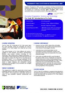
Introduction to Engine Control System Processes and Diagnostic Tools Vehicle Break-out Box
80-Pin Data Cable
I/P Cable I/P Port
50-Pin Data Cable
Vehicle ECU Harness
ECU Interface Box
To Vehicle ECU
Learning Objectives:
1. Perform a general diagnostic process regardless of the type of customer concern on ECU controlled systems. 2. Utilize advanced diagnostic tools for greater accuracy and speed. 3. Lay out the troubleshooting steps and resources you will need to follow when diagnosing customer concerns.
Engine Control Systems II - Course 874
Section 1
Introduction to Engine Control System Processes and Diagnostic Tools Overview
The purpose of this section is to: • help you understand the general diagnostic process that you will follow regardless of the type of customer concern you are troubleshooting. • features of diagnostic tools that will help you with greater accuracy and speed. • lay out the troubleshooting steps and resources you will need to follow when diagnosing customer concerns.
Diagnostic Tools and Resources
There are many troubleshooting “tools” that can be used to accurately identify and troubleshoot driveability problems. These include: • Previous Troubleshooting Experience • Use of the OBD self-diagnostic system • Service Literature – Technical Information System (TIS), Repair Manuals, Electrical Wiring Diagrams, and Technical Service Bulletins • Diagnostic Toolset • TechView There are also other resources at your disposal for those extraordinary situations where your best attempts fail to resolve the customer concerns: • Technical Assistance hotline • Area office assistance; STSs, FTSs, and FPEs With these resources available to you, even the most difficult customer concerns can be resolved while maintaining high standards for customer satisfaction.
Previous Your experience is one of the best resources you have. Depending on the Troubleshooting Experience
symptom or customer description of the driveability concern, you can often eliminate many sub-systems from your diagnostic investigations. It is important to note, however, this does not mean that troubleshooting is performed in a random manner. In fact, you will always fix the car faster and with more accuracy when you follow a systematic diagnostic approach. Engine Control Systems II - Course 874
1-1
Section 1
Use of the OnBoard (Self) Diagnostic System
All ECMs are equipped with an on-board self-diagnostic system (OBD). This system is capable of detecting shorts and opens in most sensor electrical circuits and in some actuator circuits. Later models equipped with the OBD II system can also detect component and system performance. These OBD systems are an integral part of your troubleshooting process and will weigh heavily in your diagnostic outcome.
Diagnostic Toolset
The Diagnostic Toolset consists of the Diagnostic Tester and the Vehicle Break-out Box (V-BoB). Depending on the vehicle you are working on and the nature of the customer concern, both of these tools are extremely valuable for gathering large quantities of diagnostic data in a relatively short period of time. For troubleshooting engine control system concerns, the Diagnostic Toolset allows you to quickly perform the following functions: • Read and define Diagnostic Trouble Codes (DTCs) • Display serial data stream containing sensor, actuator, and diagnostic information • Display signal voltages on a fully adjustable laboratory oscilloscope • Store and playback snapshot data. • Test sensors and actuators dynamically using Active Tests • All CARB OBD II functions
1-2
TOYOTA Technical Training
Introduction to Engine Control System Procedures and Diagnostic Tools
Diagnostic Toolset with TIS
V-BoB (Vehicle Break-out Box)
80-Pin Data Cable
I/P Cable I/P Port
50-Pin Data Cable
Vehicle ECU Harness
ECU Interface Box
To Vehicle ECU
Fig. 1-1 TL874f101
Engine Control Systems II - Course 874
1-3
Section 1
TechView
TechView is a computer-based program that works hand in hand with the Diagnostic Tester. This tool aids in collecting live data from the vehicle where the technician can view the data in a variety of formats (graphs, charts, lists) and store files for later viewing. Some of the TechView features include: • Real Time Data List • Tester Snapshot Data • DTC Information • OBD System Monitors • Freeze Frame Data • File Information Each technician creates a user name where all of the vehicle information is stored and can be used again for future reference. Before using the Diagnostic Tester, the Diagnostic Toolset Manual should be read thoroughly.
1-4
TOYOTA Technical Training
Introduction to Engine Control System Procedures and Diagnostic Tools
General OBD II Scan Tool or Diagnostic (Hand-held) Tester Procedure
If the Diagnsotic Tester cannot communicate with ECU controlled systems when connected to DLC3, the ignition switch is ON, and the Diagnostic Tester is on, there is a problem on the vehicle side or tool side. (1)If communication is normal when the Diagnostic Tester is connected to another vehicle, inspect the diagnosis data link line (Bus≈line) or ECM (ECU) power circuit of the vehicle. (2)If communication is still not possible when the Diagnostic Tester is connected to another vehicle, the problem is probably in the Diagnostic Tester itself, so perform the Self Test procedures outline in the Diagnostic Toolset Operator’s Manual.
Engine Control Systems II - Course 874
1-5
Section 1
Customer Problem Analysis
Fig. 1-2 TL874f102
1-6
TOYOTA Technical Training
Introduction to Engine Control System Procedures and Diagnostic Tools
Customer In troubleshooting, the problem symptoms must be confirmed accurately Problem and all preconceptions must be cleared away to give an accurate Analysis (1) judgment. To ascertain just what the problem symptoms are, it is extremely important to ask the customer about the problem and the conditions at the time it occurred. Important Point in The following five items are important points in the problem analysis. the Problem Past problems which are thought to be unrelated and the repair history, Analysis etc., may also help in some cases, so as much information as possible should be gathered and its relationship with the problem symptoms should be correctly ascertained for reference in troubleshooting. A customer problem analysis table is provided in the Diagnostics section for each system for your use.
The Five Major Questions Important Points in the Customer Problem Analysis • What?... Vehicle model, system name • When?... Date, time, occurrence frequency • Where?... Road conditions • Under what conditions?... Running conditions, driving conditions, weather conditions Fig. 1-3
• How did it happen?... Problem symptoms
TL874f103
Customer Problem Analysis Check Sheet
Fig. 1-4 TL874f104
Engine Control Systems II - Course 874
1-7
Section 1
Symptom Confirmation and Diagnostic Trouble Code Check (2)
The diagnostic system fulfills various functions. The first function is the Diagnostic Trouble Code Check. A malfunction in the signal circuits to the ECM is stored in code in the ECM’s memory at the time of occurrence. This DTC is retrieved by the technician during troubleshooting. Another function is the Input Signal Check, which checks if the signals from various switches are sent to the ECM correctly. By using these check functions, the problem areas can be narrowed down quickly and troubleshooting can be performed effectively. In diagnostic trouble code check, it is very important to determine if the problem indicated by the diagnostic trouble code is present or occurred in the past and returned to normal. In addition, it must be checked in the problem symptom check whether the malfunction indicated by the diagnostic trouble code is directly related to the problem symptom or not. For these reasons, the diagnostic trouble codes should be checked before and after the symptom confirmation to determine the current conditions, as shown in the following figure. If this is not done, it may, depending on the case, result in unnecessary troubleshooting for normally operating systems, thus making it more difficult to locate the problem, or in repairs not pertinent to the problem. Therefore, always follow the procedure in correct order and perform the diagnostic trouble code check.
DTC Check Procedure
Fig. 1-5 TL874f105
1-8
TOYOTA Technical Training
Introduction to Engine Control System Procedures and Diagnostic Tools
DTC Check Procedure Taking into account the points on the previous page, a flow chart showing how to proceed with troubleshooting using the diagnostic trouble code check is shown here. This flow chart shows how to utilize the diagnostic trouble code check effectively, then by carefully checking the results, indicates how to proceed either to diagnostic trouble code troubleshooting or to troubleshooting of problem symptoms table.
Fig. 1-6 TL874f106
Engine Control Systems II - Course 874
1-9
Section 1
Symptom The most difficult cases to diagnose is when no problem symptoms are Simulation (3) occurring. In such cases, a thorough customer problem analysis must be carried out, then simulate the same or similar conditions and environment in which the problem occurred in the customer’s vehicle. No matter how much experience or how skilled the technician is, to proceed to troubleshoot without confirming the problem symptoms will often result in wasted time and failure to resolve the customer concerns. For example, for a problem which only occurs when the engine is cold, the problem can never be determined so long as the symptoms are confirmed when the engine is hot. Since vibration, heat or water penetration (moisture) are likely causes for problems that are difficult to reproduce, the symptom simulation tests introduced here are effective measures to apply to the vehicle. Important Points in the Symptom Simulation Test: In the symptom simulation test, the problem symptoms should of course be confirmed, but the problem area or parts must also be found out. To do this, narrow down the possible problem circuits according to the symptoms before starting this test and connect a tester beforehand. After that, carry out the symptom simulation test, judging whether the circuit being tested is defective or normal and also, confirming the problem symptoms at the same time. Refer to the problem symptoms table for each system to narrow down the possible causes of the symptom.
Vibration Method Do not do this until you have confirmed that the recorded DTC is not present.
Fig. 1-7 TL874f107
1-10
TOYOTA Technical Training
Introduction to Engine Control System Procedures and Diagnostic Tools
Other Methods for Simulating Conditions
Fig. 1-8 TL874f108
Engine Control Systems II - Course 874
1-11
Section 1
Diagnostic The inspection procedure is shown in the following figure. This table Troubleshooting permits efficient and accurate troubleshooting using the diagnostic Check (4) trouble codes displayed in the diagnostic trouble code check. Proceed with troubleshooting in accordance with the inspection procedure given in the diagnostic chart corresponding to the diagnostic trouble codes displayed
DTC Chart
Fig. 1-9 TL874f109
1-12
TOYOTA Technical Training
Introduction to Engine Control System Procedures and Diagnostic Tools
Problem The suspected circuits or parts for each problem symptom are shown in Symptoms the table below. Use this table to troubleshoot the problem when a Table (5) “Normal” code is displayed in the diagnostic trouble code check but the problem is still occurring. Numbers in the table indicate the inspection order in which the circuits or parts should be checked. When the problem is not detected by the diagnostic system even though the problem symptom is present, it is considered that the problem is occurring outside the detection range of the diagnostic system, or that the problem is occurring in a system other than the diagnostic system.
Problem Symptoms Table
Fig. 1-10 TL874f110
Engine Control Systems II - Course 874
1-13
Section 1
Circuit How to read and use each page is shown in the following figures. This Inspection (6) chart provides the procedure to diagnose a circuit or system. Often, you will use the Diagnostic Tester, DVOM, or oscilloscope to diagnose faults in a circuit.
Circuit Inspection
Wiring Diagram
Fig. 1-11 TL874f111
1-14
TOYOTA Technical Training
Introduction to Engine Control System Procedures and Diagnostic Tools
Inspection Procedure
Fig. 1-12 TL874f112
Engine Control Systems II - Course 874
1-15
Section 1
Repair the In electrical/electronic diagnostics, you will frequently encounter Problem (7) situations where diagnosis consumes 90% of the actual repair time. By using this procedure to narrow down the number of tests you perform, you can reduce diagnostic time. After successfully locating the faulty circuit and pinpointing the fault, repair is a relatively simple matter. It is important, however, to ensure customer satisfaction after the repair by performing one last step before releasing the vehicle. On occasion, you will have to diagnose and repair vehicles with compound problems. To ensure that the vehicle is operating normally, and that the original symptom has been remedied, a quick quality control check of the vehicle is performed. This is accomplished during the Repair Confirmation step.
Repair This is always the final step in diagnosis. Regardless of how you arrived Confirmation (8) at this step, there are always several items you want to confirm before releasing the vehicle to your customer. The items you will be looking for during this quality control quick check are: • Satisfactory driveability under the problem conditions stated by the customer • Repair Confirmation (Readiness Tests) where indicated completed • All DTC(s) eliminated from ECM keep alive memory These last two items can be confirmed using the Diagnostic Tester. Once confirmed, the vehicle can be returned to the customer. You can be confident that by following these procedures, in the order given, that you will repair the vehicle with a high rate of success in the shortest possible time.
Problems Which You cannot attempt to fix a problem that does not exist. Therefore, in Cannot Be cases where the problem cannot be duplicated, better communication Duplicated with the owner, or outside assistance, may offer a solution. Owner Perception: Sometimes an owner perceives a “normal” operating condition to be a problem. The best way to identify these cases is to accompany the owner on a “road test.” Let the customer drive and point out the problem condition during the road test.
1-16
TOYOTA Technical Training
WORKSHEET 1—1 General Diagnostic Tester Procedure
(Instructors’Copy) Vehicle
Year/ Prod. Date
Engine
Transmission
Worksheet Objectives When troubleshooting using the Diagnostic Tester, there are general procedures that will aid in troubleshooting the vehicle. This worksheet will familiarize you with those procedures.
Section 1: 1. The primary purpose of the Customer Problem Analysis Check sheet is:
2. The DTC Check procedure is used to confirm if the problem is present or can be duplicated. What are three possible outcomes from this procedure?
3. What are the four methods for simulating conditions?
4. When is the Problem Symptoms Table used?
Engine Control Systems II - Course 874
1-17
Worksheet 1-1
5. Name four items of information found in the Circuit Inspection.
6. Name three items that are checked during the Repair Confirmation.
1-18
TOYOTA Technical Training
WORKSHEET 1-2 Diagnostic Tester
(Instructors’Copy) Vehicle
Year/ Prod. Date
Engine
Transmission
Worksheet Objectives Display data using a variety of Diagnostic Tester modes that will aid in troubleshooting and interpreting the results.
Tools and Equipment • Vehicle • Repair Manual, EWD, & NCF • Diagnostic Tester & Manual • Diagnostic Tester Printer • Hand Tools, Fender Covers, Floor Mats, and Shop Towels
Section 1: Setup 1. On a vehicle selected by the instructor, warm up the vehicle and connect the Diagnostic Tester to the vehicle. Refer to the Diagnostic Tester Manual for specific setup instructions if needed.
Section 2: Data List 1. Select DATA LIST mode under ENHANCED OBD II. 2. Compare All DATA List to the EXTENDED DATA List. What is the major difference between these lists?
Section 3: LED/LIST Mode 1. Select LED/LIST mode 2. Observe DATA LIST. When would you use this mode?
3. Reorder LED/LIST parameters according to instructor’s directions.
Engine Control Systems II - Course 874
1-19
Worksheet 1-2
Section 4: Bar Graph Mode 1. Select BAR GRAPH mode 2. Observe Data List. When would you use this mode?
3. Reorder LED/LIST parameters according to instructor’s directions.
Section 5: STRIP CHART Mode 1. Select STRIP CHART mode. Select and list 5 parameters as identified by the instructor.
2. Observe Data List. When would you use this mode?
Section 6: CUSTOM DATA Mode 1. Select CUSTOM DATA mode. Select and list below the 6 parameters as identified by the instructor.
2. Observe Data List. When would you use this mode?
1-20
TOYOTA Technical Training
Diagnostic Tester
Section 7: SNAPSHOT Mode 1. Select SNAPSHOT mode. Select and list below the 6 parameters as identified by the instructor.
2. Prepare to create a fault as identified by your instructor. You will create the fault during a snapshot capture. Write below the type of fault, any terminal pin numbers used, and the intended DTC.
3. Create a snapshot with the fault recorded. Replay the captured snapshot and repeat if the fault was not recorded. Remove the fault when done and return vehicle to original condition. 4. What DTC(s) were recorded?
5. Clear DTC(s) 6. When would you use SNAPSHOT mode?
7. Switch to another team’s SNAPSHOT file and diagnose the cause. What was the fault?
Vehicle:
Fault:
Vehicle:
Fault:
Vehicle:
Fault:
Engine Control Systems II - Course 874
1-21
Worksheet 1-2
1-22
TOYOTA Technical Training
Diagnostic Tester Name: __________________________________________________________ Date: _________________________ Review this sheet as you are doing the worksheet. Check each category after completing the worksheet and instructor presentation. Ask the instructor if you have questions. The comments section is for you to write where to find the information, questions, etc.
I have questions Topic
I know I can Comment
Open Data List in CARB and ENHANCED OBD View data in LIST/LED format and describe the advantage of this mode View data in Strip Chart mode and describe the advantage of this mode Save and view a SnapShot and describe the advantage of this mode Interpret vehicle condition based on Data Lists Retrieve DTC(s), Freeze Frame and CARB Readiness data
Engine Control Systems II - Course 874
1-23
Worksheet 1-2
1-24
TOYOTA Technical Training
WORKSHEET 1-3 TechView Operation
(Instructors’Copy) Vehicle
Year/ Prod. Date
Engine
Transmission
Worksheet Objectives In this worksheet, you will diagnose a vehicle by viewing the vehicle’s Real Time Data. You will then practice saving and opening files.
Tools and Equipment • Diagnostic Tester • TIS with Tech View • Hand Tool Set
NOTE: Follow the instructions and steps in the TechView Guide before proceeding. Section 1: Problem Solving using TechView 1. Under the direction of the instructor, create a problem with the vehicle. 2. Save the DATA LIST only. Make sure the problem can be seen from the DATA LIST. Clear DTC(s) from the vehicle. 3. You will rotate through the other workstations. Write down the vehicle and the cause of the problem.
Engine Control Systems II - Course 874
1-25
TechView Operation Name: __________________________________________________________ Date: _________________________ Review this sheet as you are doing the worksheet. Check each category after completing the worksheet and instructor presentation. Ask the instructor if you have questions. The comments section is for you to write where to find the information, questions, etc.
I have questions Topic
I know I can Comment
Open a new file
Save a file
Open and resave an existing file Display data in all TechView formats and describe the advantage of each mode Save Data Lists in TechView
Retrieve DTC(s), Freeze Frame and CARB Readiness data
Retrieve SnapShot data
Interpret data from TechView to diagnose the root cause of a problem
Engine Control Systems II - Course 874
1-27