Inverse Workflows for Supporting Agile Business Process Management Thomas Sauer rjm business solutions GmbH 68623 Lampertheim, Germany
[email protected]
Mirjam Minor and Ralph Bergmann University of Trier Department of Business Information Systems II 54286 Trier, Germany {minor,bergmann}@uni-trier.de
Abstract: Agile processes allow organizations to flexibly react on new and unforeseen situations. However, modifications must adhere to the standards and quality requirements given by an organization. In this paper, the concept of inverse workflows is presented to support organizations in meeting this goal. Inverse workflows provide a means to explicitly express unwanted procedures and work situations. In conjunction with an automated system to detect inverse workflow enactment, organizations can prevent undesired developments while they are emerging. This effectively allows controlling overall process quality while modeling or adapting business process to stakeholder demand.
1 Introduction Workflow management has been found useful in many organizations for controlling and improving the quality of the goods produced and the services offered. To this end, workflows automate business processes for reducing wait times, guiding human process participants, or providing resources as required. However, organizations face the challenge that processes have to be quickly adapted to reflect new requirements or shifting customer priorities. To accommodate new customer demands, new tasks may have to be incorporated, or new connections between already known tasks need to be drawn. This leaves the risk that task sequences emerge which have been learned to be harmful in the past, or which may lead to sub-standard results. In this paper, the concept of inverse workflows is presented to lower this risk. Inverse workflows consist of a workflow definition providing a process template which describes an unwanted procedure. This goes beyond exceptions [RvdAtHW06] such as a work item failure, a deadline expiration, or a constraint violation like a hurt credit limit. For example, an unwanted procedure may describe a sequence of tasks which will lead to data loss when enacted. If a procedure becomes unwanted only under specific circumstances, e.g., if a product develops qualities known as problematic, inverse workflows include respective workflow enactment characterizations. These characterizations express undesired data or task states which may result from executing the underlying workflow definition. To provide a warning as soon as the work situations described by an inverse workflow
emerges, the Progress Information Environment (PIE) [Sau10] is used. PIE provides automated workflow enactment tracking, which evaluates the data produced by organization members while they are carrying out activities, and identifies the state of the latter along an ideal process model. In particular, this is applicable to inverse workflows, such that undesirable developments can be spotted and corrected in a timely manner. Inverse workflows follow the notion of inverse requirements known from Software Engineering [LD03]. Inverse requirements explicitly specify properties a system is not intended to have, in order to clarify system behavior. Inverse workflows also borrow on the idea of specifying nonfunctional safety and security requirements, which describe hazards a software system must not expose [VL10]. In workflow management, specifying unwanted work situations has been addressed so far by specifying forbidden behavior [SM06] or anti-patterns [TSvdA09]. Inverse workflows exceed these approaches by providing an intuitive concept which can be employed regardless of the process description language or modeling environment preferred by an organization. While applicable to any workflow management strategy, the concept of inverse workflows has been found most useful in agile scenarios, where workflow definitions are frequently changed. The concept is evaluated in the field of geographical information management [SMMB06]. This includes traditional workflow management strategies, but also agile ones, where workflow definitions are frequently changed. The paper is organized as follows. In Section 2, foundations are presented for expressing domain-independent workflow definition and enactment. Section 3 discusses how this is applied for describing inverse workflows. Related work is discussed in Section 5. A short conclusion given in Section 6 closes this paper.
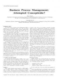
2 Workflow Definition and Enactment Inverse workflows can be described in any process description language which allows expressing self-contained tasks and their interdependencies, such as EPC, UML Activity Diagrams, or BPMN. For formally describing the building blocks of an inverse workflow independent of a specific description language, in the following the light-weight model of abstract workflow definition and enactment introduced in [Sau10] is used. In this model, any process followed by an organization is described by a workflow definition comprising a set of tasks and their control-flow relationship. Each task represents an activity that can be performed by a human or a machine. Tasks may range from short-term decisions such as selecting between two alternatives, to more complex activities such as writing a report. Specialized trigger tasks may even launch entire processes based on another workflow definition, similar to calling a subroutine in a programming language. Carrying out a workflow definition leads to workflow enactment. The concrete efforts in enacting the workflow definition form a workflow instance or simply a workflow. The tasks are performed as previously arranged, with their findings expressed as data objects. Each task traverses three states “inactive”, “active”, and “completed”, which are all characterized by the data available. While a task has not produced any data objects yet, it remains
t1
t2
(inactive, 1)
(completed, 0)
d1
d1, d2
t3 (active, 0) (l, r) d1, d2, d3
C
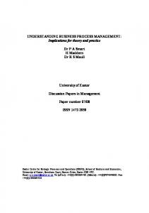
Figure 1: Instantiation and enactment of a workflow definition.
in state “inactive”. After intermediate data objects have been created, but control flow has not been passed to successor tasks, the task becomes “active”. With the final results produced, and control flow passed to successor tasks, a task becomes “completed”. After completing a task, its successors may use the data objects available to produce further workflow results. As workflow definitions may contain loop constructs, a task can traverse each task state more than once. The work situation reached by a task is fully represented by a task enactment characterization. This characterization is a triple (C, l, r) comprising a combination of the data available C, the applicable task state label l, and a number of repetitions r. In Figure 1, a workflow definition and its enactment is illustrated based on the modeling language introduced in [MTSB08]. A workflow definition consisting of three tasks t1 , t2 , and t3 arranged in a loop is enacted. Task t1 has been performed before, with its results represented by data object d1 . As task t1 is already available for another iteration, its task state is specified as “inactive”. The number of repetitions given by r = 1 indicates that t1 has been fully completed one time before. Using data object d1 , task t2 has been recently completed. The task created an additional data object d2 , and the task state t2 is “completed”. The value r = 0 represents that there have been no previous completions. Finally, task t3 has been started, using the data objects created previously. Task t3 has produced intermediate result d3 , leading to the set C = {d1 , d2 , d3 } of currently available data objects. Task t3 has not passed control flow yet, such that it is described “active”. Since it has not been completed before, it holds r = 0. For each task, the work situation reached is specified by a task enactment characterization comprising the set of data objects currently available C, the task state, and the number of repetitions performed. For example, the task enactment characterization for t3 is given by ({d1 , d2 , d3 }, active, 0). The combination of these task enactment characterizations leads to a workflow enactment characterization, describing a “snapshot” of the workflow enactment performed so far. It lists the task enactment characterization triples for each task contained in a workflow definition. Accordingly, the overall work situation illustrated in Figure 1 is described as {(t1 , {d1 , d2 , d3 }, inactive, 1), (t2 , {d1 , d2 , d3 }, completed, 0), (t3 , {d1 , d2 , d3 }, active, 0)}.
3 Specifying Inverse Workflows Workflow definitions aim at the automation of business processes. These processes typically describe how to produce goods or how to provide a service as intended by an orga-
CAD data conversion
Connect features
Copy data
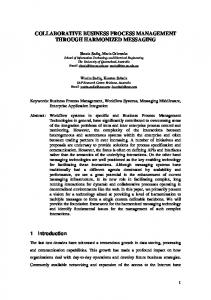
(a) Data loss: Every enactment of this workflow definition will lead to data loss.
Print overview map
[L
Print detail map
L]
(active, 10) map1 : Hardcopy municipality = “A3” name = “Overview” creator = ? ...
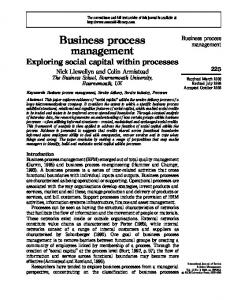
(b) Waste of resources: In the characterized work situation, an unnecessary amount of paper is produced.
Figure 2: Inverse workflow examples
nization, such that workflow definitions often represent well-tested best practices. During everyday operations, adaptation of these practices is almost inevitable. Ever-changing customer demand typically requires an organization to evolve and extend existing workflow definitions, or to introduce entirely new ones. However, the modifications applied may also lead to unintentional results, accidentally integrating procedures known as inefficient, error-prone or even dangerous into the workflow definitions followed by an organization. In result, sub-standard products are created, or suboptimal task sequences are enacted. Organizations can explicitly describe unwanted procedures already known by specifying inverse workflows. Each inverse workflow consists of a workflow definition, and a set of workflow enactment characterizations. The workflow definition describes a procedure which is known as ineffective, expansive, or even harmful, because, e.g., efforts are duplicated or safety measures are violated. The workflow enactment characterizations describe concrete work situations which have led to data objects with one or more undesired qualities, such as a report document referencing to an outdated standard. Alternatively, the workflow enactment characterizations may document unwanted task states or repetition counts, like an excessive amount of repetitions performed for a specific task. If the workflow definition providing the basis for the inverse workflow unconditionally leads to unwanted effects, workflow enactment characterizations may be omitted. In Figure 2, two typical inverse workflows are presented as observed within the field of geographical information management. In the first, a task sequence is depicted which is known to lead to data loss. The task “CAD data conversion” creates database records which would be removed by the subsequent “Connect features”, and conveyed to a production system by “Copy data”. This sequence is to be unconditionally avoided, such that no workflow enactment characterizations are specified. In the second example, an inverse workflow describes potential waste of resources. When the task “Print overview map” results in a relatively small hardcopy of size A3, the region of interest may not have been properly selected, as a typical hardcopy is at least of size A2 or larger. If in addition, the
task “Print detail map” is performed more than ten times in a row, an unnecessary amount of paper is produced. Inverse workflows complementing desired workflow definitions. Inverse workflows can refer to situations which are not covered by desired workflow definitions. For example, the first inverse workflow shown in Figure 2(a) is not covered by any other workflow definition. Thus, the task sequence expressed can only be reached if workflow definitions are adapted accordingly, e.g., by a novice workflow modeler. By modeling the unwanted sequence explicitly, the changed workflow definition can be checked whether unwanted aspects have emerged, which is discussed below in detail. Most extreme, an organization may only state inverse workflows, implicitly allowing all other workflows. This can be useful in highly dynamic or agile scenarios, when it is only known what is not wanted, and desirable procedures still have to be developed. Inverse workflows as corner-cases. Inverse workflows may also overlap with other, desired workflow definitions. In this case, the situation described can be reached by following another workflow definition, but only on rare occasion. The inverse workflow illustrated in Figure 2(b) exhibits an example. The sequence of tasks illustrated is contained as-is within another workflow, but the workflow enactment characterization specify undesirable corner cases. This can be useful to avoid a large number of case distinctions through XOR-elements or similar, leading to simplified workflow definitions which are easier to understand. In extreme, all case distinctions would be moved to inverse workflows, making them complementary as stated above.
4 Detecting Inverse Workflow Enactment By specifying inverse workflows, organizations explicitly document unwanted procedures, which, ideally, are never enacted. However, when workflow adaptation is possible, this cannot be guaranteed. In order to prevent squandering of resources, sub-standard products and services, or even dangerous situations, organizations must be warned whenever inverse workflows are enacted. This can be accomplished by using the Progress Information Environment (PIE) [SMW08, Sau10]. PIE is a Multi-Agent System (MAS, [Wei00]) designed for providing automated workflow enactment tracking. The PIE system evaluates the data produced by workflow participants while carrying out their everyday activities, and identifies the work progress achieved along previously defined workflow definitions. In particular, this allows detecting enactment of inverse workflows. PIE employs four different types of software agents, which are arranged on respective layers. The overall system resides on a base layer comprising the information systems deployed, e.g., databases or document repositories. On a layer above, sensor agents connect to these systems, transforming the data created and modified into more general data objects for further evaluation. On the next layer, task agents assess whether the data objects found indicate actual task results. On top, instance agents determine the workflow instances the task results possibly belong to. The topmost layer hosts workflow agents providing a consistent view on the work progress achieved with respect
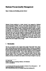
Figure 3: The PIE system displaying current workflow enactment.
to the workflow definitions used. Figure 3 shows a screenshot of such view presented by the PIE system. Sensor agents transform content specific to a particular information system into concepts understood by agents on the task, instance, and workflow layers. For example, when a team member enacts the task “Print overview map” as shown in Figure 2(b), information about the hardcopy is stored within a print server log file. An according sensor agent transforms the log entries into a data object of type “Hardcopy” to characterize task results. Task agents apply Case-Based Reasoning (CBR) [BAM+ 09] to evaluate the data objects provided by sensor agents. To this end, task agents compare the data objects received with those contained in task enactment characterizations known from past enactment efforts. Each of these characterizations serves as a task enactment case which correlates a known set of data objects with a concrete task state label and an applicable number of task repetitions. The set of task enactment cases available to a task agent forms its case base representing the experience made in enacting the according task before. When a task is enacted again under similar conditions, results similar to those observed before are expected. Hence, if a task agent finds the data objects received from sensor agents to be similar to those contained in a past task enactment characterization, the latter are reused for expressing that the task of interest to the task agent has been enacted again. This makes it possible to detect enactment of tasks even if no exact match is possible. Instance agents determine the most appropriate workflow instances which may belong to the task enactment cases provided by task agents. A number of heuristics are applied to determine the relationship between task enactment and workflow enactment efforts already
present. For example, during workflow enactment, the data objects created are likely to share a business case number, or other instantiation criteria. Thus, when data objects are similar to these already observed, task enactment is considered related to the respective workflow instance. Finally, for every possible pair of task enactment cases and workflow instances reported by corresponding instance agents, the workflow agents determine whether the case represents progress following on a situation found previously. If so, one or more workflow enactment steps are proposed to explain the task enactment results expressed by the case. The current work situation is given as workflow enactment characterizations for each workflow definition available. Issuing Warnings. When PIE has determined a workflow instance based on the workflow definitions specified for inverse workflows, management roles can be warned, such that countermeasures can be taken. If concrete workflow enactment characterizations have been given, they are compared against the respective characterization found using CBR. Warnings are then only issued if they exceed a certain minimum similarity. This allows for a flexible and intuitive specification of inverse workflows. As illustrated in Figure 2(b), it is sufficient that within data objects, only attributes of interest are given. If the current situation is found problematic in a post-mortem analysis, the according workflow enactment characterization can be reused to specify an inverse workflow. For example, when a waste of resources has been detected as depicted in Figure 2(b), the concrete workflow enactment characterization presented by PIE can be used to describe the unwanted situation. PIE is capable in detecting parallel workflow enactment, such that it is well-suited in detecting inverse workflows which overlap other, desired processes. Furthermore, its agent-oriented design makes it flexible to support adaptive workflows. Whenever workflow definitions change, including those serving as the basis for inverse workflows, the agent society of the PIE system is reconfigured to match the changed workflow definitions. This supports stepwise refinement of workflow definitions describing both desired and inverse workflows as often required in organizational practice. Evaluation. As of this writing, the approach is evaluated within the DenkXweb eGovernment project [SMMB06] conducted at the rjm business solutions GmbH. The project aims at providing geographical information on monuments, which requires to represent the location and dimension of tens of thousands of historic sites as exactly as possible. For managing this large amount of data, the project participants follow best practices expressed as workflow definitions, using a complex set of custom tools as well as commercial off-the-shelf software. The PIE system has been deployed at rjm using eight sensor agents and 35 task agents. PIE has proven to be capable in recognizing work progress at a high level of detail [Sau10]. To evaluate the concept of inverse workflows, inverse workflow definitions are currently developed by conducting interviews with stakeholders, and by analyzing historic data. For several hundred workflow instances, performance data is available, such as duration, or defect count within end products. This data is compared to expectations, and the reasons for any deviations are discussed with domain experts. The examples presented above are among the first results. In a controlled experiment, it is planned to configure instance and
workflow agents according to the inverse workflows found, to determine whether undesired situations are detected during everyday activities.
5 Related work One of the key aspects of workflow management is to support organizations in continuously improving their business processes. In order to prevent undesired development when designing or adapting workflow definitions, process modeling assistance has been widely discussed. In [FES05], the use of patterns is suggested for providing such assistance. The patterns express proven steps in, e.g., assuring a specific quality, which can be integrated into arbitrary business processes. However, while patterns may foster reuse of proven concepts and solutions, they can make future adaptation significantly harder, as the concerns expressed by a pattern cannot be easily distinguished from the actual business aspects. This problem is avoided in [TSvdA09] by describing anti-pattens. Similar to the idea of denoting inverse workflows, the authors propose to explicitly describe unwanted enactment behavior, e.g., livelocks. The anti-patterns are expressed in temporal logic, which allows applying verification techniques to determine whether a process design may lead to undesired effects. On the downside, the chosen notation makes it hard to express domain-specific anti-patterns observed during organizational practice. A business-oriented specification of forbidden behavior is suggested in [SM06]. This approach uses EPCs to denote unwanted workflows, resembling the inverse workflow approach. The specification of forbidden behavior focuses on verifying business processes during design time by using transformations to specialized Petri nets. As pointed out in [RvdA08], however, this may not be sufficient to prevent unwanted behavior in a real work environment. Especially with human workflow participants involved, the authors argue that it is required to perform conformance checking of processes based on actual work results. The inverse workflow approach pursues this idea using the PIE system. In Knowledge Management, knowledge patterns and knowledge anti-patterns have been studied for documenting knowledge and experiences [RFR09]. Ideally, such patterns arise from multiple knowledge management activities. Templates can be used for describing (anti-)patterns including (multiple) solutions, e.g. in a Wiki. Typically, the occurrence of a knowledge pattern or anti-pattern is detected by a human, and the solutions, e.g. “divide and conquer” for the anti-pattern “knowledge blob”, are applied manually as well. Inverse workflows follow the idea of inverse requirements known from the fields of Software Engineering. Inverse requirements describe concepts a software system is not intended to deal with [LD03]. Typically, this is used to clarify the concepts addressed in order to specify the scope of implementation more clearly. Inverse workflows also borrow on the idea of specifying nonfunctional safety and security requirements. Sometimes also called negative requirements or “shall-not” requirements [VL10], these describe hazards a software system must not expose. For example, it may not be allowed to transfer input data over an unsecured communications channel. For thread and hazard analysis, negative scenarios similar to inverse workflows are de-
noted as misuse cases [Ale03]. They describe the effects of a failing device, severe environmental conditions, or even sabotage through an attacker. By explicitly denoting misuse cases, appropriate solutions can be elicited, e.g., by adding exception handling to subsystem functions. As with regular use cases, misuse cases also support the generation of test cases. This is similar to the idea of tracking inverse workflow enactment, but is limited to pre-deployment stages of a software system. In contrast, PIE system allows to monitor processes in situ. Such constant monitoring is also discussed for intrusion detection [CB07]. Using state machines describing typical attack scenarios, undesired developments are detected. However, as with anti-patterns described above, the chosen formalism makes it hard to adapt the idea to other scenarios.
6 Conclusion In this paper, the concept of inverse workflows has been presented to explicitly express undesired work situations. Using a system to automatically track the enactment of inverse workflows, situations known as inefficient, error-prone, or even dangerous can be detected as they emerge. This adds a “safety net” to modeling activities, effectively supporting organizations in adapting their workflow definitions. Modifications and extensions unintentionally leading to procedures known as unwanted are noticed in time, such that countermeasures can be taken as soon as possible. So far, inverse workflows have been found useful for geographical information management. However, the concept is not limited to any particular application domain or modeling methodology. The presented approach is based on a light-weight formalism of workflow definition and enactment. This ensures that inverse workflows can be easily used in any organization regardless of the process description language or modeling tool preferred. Further, the PIE system to perform automated workflow enactment tracking has been designed domain-independently. Its agent-oriented design allows stepwise refinement of workflow definitions describing both desired and inverse workflows.
References [Ale03]
Ian Alexander. Misuse Cases: Use Cases with Hostile Intent. IEEE Software, 20(1):58–66, 2003.
[BAM+ 09]
Ralph Bergmann, Klaus-Dieter Althoff, Mirjam Minor, Meike Reichle, and Kerstin Bach. Case-Based Reasoning: Introduction and Recent Developments. K¨unstliche Intelligenz, 23(1):5–11, 2009.
[CB07]
George Cybenko and Vincent H. Berk. 40(1):62–70, 2007.
[FES05]
Alexander F¨orster, Gregor Engels, and Tim Schattkowsky. Activity Diagram Patterns for Modeling Quality Constraints in Business Processes. In Proceedings of the 8th International Conference on Model Driven Engineering Languages and Systems (MoDELS 2005), volume 3713 of LNCS, pages 2–16. Springer, 2005.
Process Query Systems.
Computer,
[LD03]
Julio Cesar Sampaio do Prado Leite and Jorge Horacio Doorn. Perspectives on Software Requirements, volume 753 of International Series in Engineering and Computer Science. Springer, 2003.
[MTSB08]
Mirjam Minor, Alexander Tartakovski, Daniel Schmalen, and Ralph Bergmann. Agile Workflow Technology and Case-Based Change Reuse for Long-Term Processes. International Journal on Intelligent Information Technologies, 4(1):80–98, 2008.
[RFR09]
J¨org Rech, Raimund L. Feldmann, and Eric Ras. Knowledge Patterns. In M. E. Jennex, editor, Encyclopedia of Knowledge Management (2nd Edition). IGI Global, 2009.
[RvdA08]
Anne Rozinat and Wil M. P. van der Aalst. Conformance checking of processes based on monitoring real behavior. Information Systems, 33(1):64–95, 2008.
[RvdAtHW06] Nick Russell, Wil M. P. van der Aalst, Arthur H. M. ter Hofstede, and Petia Wohed. On the suitability of UML 2.0 activity diagrams for business process modelling. In Proceedings of the 3rd Asia-Pacific Conference on Conceptual Modelling (APCCM 2005), volume 53 of CRPIT, pages 95–104. Australian Computer Society, 2006. [Sau10]
Thomas Sauer. Automated Enactment Tracking for Dynamic Workflows. PhD thesis, University of Trier, 2010.
[SM06]
Carlo Simon and Jan Mendling. Verification of Forbidden Behavior in EPCs. In Proceedings of the GI Conference Modellierung (MOD2006), volume 82 of LNI, pages 233–242. GI, 2006.
[SMMB06]
Thomas Sauer, Kerstin Maximini, Rainer Maximini, and Ralph Bergmann. Supporting Collaborative Business through Integration of Knowledge Distribution and Agile Process Management. In Multikonferenz Wirtschaftsinformatik 2006 (MKWI 2006), pages 349–361, 2006.
[SMW08]
Thomas Sauer, Mirjam Minor, and Sascha Werno. An Agent-oriented System for Workflow Enactment Tracking. In Proceedings of the 17th IEEE International Workshop on Enabling Technologies: Infrastructure for Collaborative Enterprises (WETICE’08), pages 235–240, 2008.
[TSvdA09]
Nikola Trcka, Natalia Sidorova, and Wil M. P. van der Aalst. Data-Flow AntiPatterns: Discovering Dataflow Errors in Workflows. In Proceedings of the 21st International Conference on Advanced Information Systems (CAiSE’09), volume 5565 of LNCS, pages 425–439. Springer, 2009.
[VL10]
Jeffrey Voas and Phil Laplante. Effectively Defining Shall Not Requirements. IEEE IT Professional, 12(3):46–53, 2010.
[Wei00]
Gerhard Weiss. Multiagent Systems – A Modern Approach to Distributed Artificial Intelligence. MIT press, 2000.