Multicast for IPTV Delivery. Distribute information to large audiences over an IP
network ..... Carries traffic across RFC2547 compatible L3 VPN. With aggregation
.
IP Multicast and Multipoint Design for IPTV Services
Mike McBride
© 2008 Cisco Systems, Inc. All rights reserved.
1
Session Goal To provide you with a thorough understanding of the end-to-end protocol, mechanics and service element of IP multicast technologies used in IPTV networks.
© 2008 Cisco Systems, Inc. All rights reserved.
22
Agenda Introduction Architectural overview IP multicast primer (SSM) Transit Transport Design options Native (PIM), mLDP, RSVP-TE P2MP, L2/L3VPN, signaling
Resiliency Source redundancy, protected pseudowires, FRR, live-live, MoFRR
Broadband Edge IGMP snooping, MVR, vVLAN, DSL, Cable, FTTH
Path selection ECMP, multi topologies, RSVP-TE P2MP
Admission control Channel changing Join/leave latency, static/dynamic forwarding, acceleration
© 2008 Cisco Systems, Inc. All rights reserved.
3
Introduction IPTV and IP multicast
© 2008 Cisco Systems, Inc. All rights reserved.
4
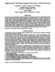
Multicast for IPTV Delivery
Network Traffic
Distribute information to large audiences over an IP network
8 6 4 2 0 1
Multicast 1. Efficiently Controls network traffic 2. Reduces server and CPU loads 3. Eliminates traffic redundancy
Multicast Unicast
20
40
60
# Clients
80
100
Multicast Benefits • Increase Productivity & Save Cost • Generate New Revenue Stream
4. Makes Multipoint applications possible
© 2008 Cisco Systems, Inc. All rights reserved.
5
IP Multicast Is a Green Technology!!!!!!!! Internet Protocol (IP) multicast is a bandwidth-conserving technology that reduces traffic by simultaneously delivering a single stream of information to thousands of corporate recipients and homes; applications that take advantage of multicast include videoconferencing, corporate communications, distance learning, and distribution of software, stock quotes, and news Facts Multicast reduces the number of servers required—Unicast uses many servers which must process individual requests for streaming media content from tens, hundreds or thousands of users and then send duplicated streams Reducing the number of network resources required not only saves capital costs and operating expenditure but also saves power which in turn reduces carbon footprint It requires 838 pounds of coal to power one PC for one year
© 2008 Cisco Systems, Inc. All rights reserved.
6
Broadcast IPTV = IP multicast …however transport network transits packets .. “Native IP multicast”, MPLS, L2, optical
IP multicast sources: Encoder, Transcoder, Groomer, Ad-Splicer, …
IP multicast receivers: Transcoder, Groomer, Ad-Splicer, QAM, STB
IP == IPv6 (Japan) or IPv4 (RotW rest of the world) No address exhaustion issue (SSM) No/slow move to IPv6 for IPTV in RotW
© 2008 Cisco Systems, Inc. All rights reserved.
7
Deployment strategy Overview, Recommendation Network Add IP multicast to your network core Choose transport methods based on SLA and operational requirements/preferences Native IP multicast, MPLS, L2, mix Solution should minimize involvement in provisioning of individual applications/services
IPTV services Start with traditional broadcast TV Investigate extending IPTV and other (IP multicast) services More RoI on network layer investment
© 2008 Cisco Systems, Inc. All rights reserved.
8
Additional service opportunities Across common SSM IP multicast service No need to change the IP multicast functionality in the network May want improvements on optional elements (RSVP, …)
Extending IPTV broadcast service Dynamic redundancy (regional to national) Variety of reach of transmission (src->rcvr) Groomer/transcoders, Add-Splicers Switched Digital Video, oversubscription Wholesale, dynamic, international channels
Other services Commercial (MVPN) Content pre-provisioning to VoD server, STB Multicast in Internet Service (eg: To PC) Voice conferencing, gaming, surveillance, … © 2008 Cisco Systems, Inc. All rights reserved.
9
Architectural Overview
© 2008 Cisco Systems, Inc. All rights reserved.
10
50,000 feet architecture IPTV and multicast IP multicast Solution level gateway
Signaling
Service Interface
Signaling
Receive/process/send Eg: ad-splicer, Dserver, transcoder,…
IP multicast source
IP multicast receiver
Signaling
IPTV “Services Plane”
The network “Network Plane” © 2008 Cisco Systems, Inc. All rights reserved.
11
50,000 feet architecture Goals Separate “network” and “services” plane Network = shared infrastructure for all services Routers, switches, optical gear, NMS, … IPTV = encoders, groomers, splicers, VoD server, STB, … Often operated by different entity/group than network
IP multicast Allow to attach solution plane devices (sourcing, receiving) anywhere – global, national, regional, local. Start/stop sending traffic dynamically, best utilize bandwidth only when needed.
One network technology usable for all services (IPTV, MVPN, …) Enable network operator not to provision/worry about individual programming.
Service Interface How network & service operator infrastructure interacts with each other SLA of IP multicast traffic sent/received Signaling used © 2008 Cisco Systems, Inc. All rights reserved.
12
Service Interface Basic service description (recommended IP multicast for IPTV)
P2MP = SSM tree (traffic forwarding) Build trees from any individual source. Easy to: Inject everywhere, receive everywhere (securely) Best join/prune latencies Warning: fast network join is not same as fast solution join!
Largest #trees supported,… No coordination of tree addresses (SSM channels) No spoofing of traffic across the tree
Redundancy Source redundancy: Anycast/Prioritycast Optional live-live service (path separation) (for up to 0 packet loss during network failure) © 2008 Cisco Systems, Inc. All rights reserved.
13
Service Interface More features Admission control Per-flow bandwidth based admission control RSVP-TE, RSVP/UPnP-CAC at edge Router local admission control
More …: (per subscriber) access control (eg: lineup), provisioning of subscriber policies, … Accounting (Radius, Netflow, …) Management, troubleshooting Not further covered in this presentation Lots of product specifics
© 2008 Cisco Systems, Inc. All rights reserved.
14
Service Interface Expectation against service devices Mandatory: SSM-tree building: IGMPv3/MLDv2 with SSM ‘joins’ receivers needs to know (S,G) channels to join Send multicast packets with TTL > 1
Optional: DSCP setting Signaling for source redundancy Send/receive traffic twice (redundancy and/or live-live) RSVP/UPnP-CAC – for admission control
Workarounds in network Static building of multicast trees, SSM transition, DSCP marking, router based CAC, … © 2008 Cisco Systems, Inc. All rights reserved.
15
Network infrastructure Only implicitly impacting services (resilience, security,..)
Preferred choice of transport: IP (native multicast/PIM) or MPLS (mLDP and RSVP-TE P2MP)
Path selection (dual path) – MoFRR or exposed to service Tree cost optimization Load-splitting: ECMP: PIM and mLDP Arbitrary: RSVP-TE (CSPF)
Preferred choice of virtualization L2VPN, L3VPN context – or why not…
…not complete list © 2008 Cisco Systems, Inc. All rights reserved.
16
IP multicast primer (SSM) … as required for IPTV…
© 2008 Cisco Systems, Inc. All rights reserved.
17
Protocols and Services …and IP multicast multicast / multipoint protocols Between routers, switches, .. “Only of interest to network operator” PIM-SM, MSDP, (M)BGP, AutoRP, BSR, mLDP, RSVP-TE, …), IGPs (OSPF, ISIS), …
multicast services How end-devices can use IP multicast “Of interest to network and service operator” ASM, SSM (and protocols “IGMP/MLD”) Service operator just need to add SLA requirements!
© 2008 Cisco Systems, Inc. All rights reserved.
18
IP multicast services ASM: “Any Source Multicast” (1990, rfc1112) The “traditional IP multicast service” (collaborative) Sources send packets to multicast groups Receivers join to (G) groups, receive from any source
SSM “source specific multicast” (~2000, rfc4607/4604) The multicast variant for IPTV (or other “content distribution”) Unchanged: Sources send packets to multicast groups Receivers subscribe (S,G) channels, receive only traffic from S sent to G Primarily introduced (by IETF) for IPTV type services Because of limitations of standard (protocol) model for ASM
© 2008 Cisco Systems, Inc. All rights reserved.
19
Standard protocol model for ASM What is the standard protocol model ? A1: MBone and DVMRP Please go back to your time machine and dial 1994
A2: Native Multicast with: PIM-SM AutoRP, BSR or MSDP/Anycast-RP redundancy MSDP for Interdomain support Multiprotocol BGP for interdomain RPF selection
Best available general purpose ASM protocol suite …but with issues © 2008 Cisco Systems, Inc. All rights reserved.
20
IP multicast services Issues with ASM – resolved with SSM
ASM DoS attacks by unwanted sources Address allocation
Standard protocol suite Complexity of protocol operations required PIM-SM (RPT+SPT+Switchover), RP redundancy, announce, location MSDP (RPF), BGP congruency, Interactions with MPLS cores, bandwidth reservation, protection
Scalability, Speed of protocol operations (convergence) RPT + SPT operations needed
© 2008 Cisco Systems, Inc. All rights reserved.
21
End-to-end protocol view Historic development National content
Aggregation
Access
Home Net
Receiver Disk in every Agg. region
Regional/ local content
PE-AGG
DSLAM
Home Gateway
STB
Old designs: Use non-IP satellite distribution, inject regional / locally “National IP network can not transport video (cost, function)”
Current designs: use regional/local injection only for regional/local content The national core IP network can transport video perfectly May also want to feed local/region back across core (national redist) © 2008 Cisco Systems, Inc. All rights reserved.
22
End-to-end protocol view example: L3 aggregation Same choices for all access technologies
External Network
Core
Eg: Content provider
Distribution / regional
Aggregation
Dis. Edge Rtr
PE-AGG
Access BB type specific
Home Net Home Gateway
STB
?
Video encoder/ multiplexer First hop router
Content injection: External, national, regional, local PIM-SSM (S,G) joins
Headend
Different by access technology
IGMPv3 (S,G) membership
L3 Transport Options in clouds: Opt. Source Redundancy
Native: PIM-SSM or MVPN/SSM MPLS: LSM / mLDP RSVP-TE PIM-SSM
© 2008 Cisco Systems, Inc. All rights reserved.
PIM-SSM
IGMP: {Limits} {Static-fwd} PIM-SSM
IGMPv3 IGMPv3 IGMPv3 snooping proxy routing SSM 23
Transit Transport design options
© 2008 Cisco Systems, Inc. All rights reserved.
24
Transport architecture Overview Common deployments: Native PIM-SSM or MVPN Concentrate on futures / components Support for MPLS multicast (LSM) Build P2MP / MP2MP label switched delivery trees
mLDP (P2MP, MP2MP), RSVP-TE P2MP Put traffic into a VPN context As a method of service isolation / multiplexing
Using L2 vs. L3 on PE nodes To “integrate” better into an L2 service model
Redefine PE-PE signaling for MVPN
© 2008 Cisco Systems, Inc. All rights reserved.
25
Overview Elements of transport architecture for tree building • C(ustomer)-tree building protocols IPTV: IGMPv3 / PIM-SSM
• P(rovider)-tree (PMSI) building protocols Native: PIM-SSM/SSM/Bidir, MPLS: mLDP, RSVP-TE
• PE mapping: C-tree(s) to P-tree 1:1/N:1 (aggregation) ; ‘native’/VPN (L2, L3) ; static/dynamic
• PE-PE (“overlay”) tree signaling protocols Optional PIM or BGP (extensions) Not needed: native IPv4/IPv6, ‘direct-MDT’ mLDP, static mapping Receiver Content Source
CE2
P2
PE1
Upstream PE = Headend LSR © 2008 Cisco Systems, Inc. All rights reserved.
PE2
CE2 Tailend LSRs =
P1
Downstream PEs
P4
PE3
CE3 Receiver
26
Combinations with L3 on PE Current widely deployed
• “Native IP multicast” (IPv4/IPv6) IPv4/IPv6 PIM-SSM in core User side = core tree: No PE-PE signaling required. “RPF-Vector” for “BGP free core”
“MVPN”(PIM) Carries traffic across RFC2547 compatible L3 VPN. With aggregation IPv4 PIM-SSM/SM/Bidir in core (IPv4) RFC2547 BGP ; GRE encap/encap on PE PE-PE signaling required I-PMSI = Default-MDT ; SI-PIMSI = Data-MDT BGP extensions for InterAS and SSM support © 2008 Cisco Systems, Inc. All rights reserved.
27
Deploying MPLS-Based L3 VPNs and… Seattle
NYC
How can I get IP multicast traffic to go from San Jose to New York City and Seattle?
RFC-2547 MPLS-Based Core
San Jose
© 2008 Cisco Systems, Inc. All rights reserved.
28
Multicast VPN: Challenges Multicast not originally supported with MPLS (RFC 2547) Workaround was point-to-point GRE tunnels from CE to CE Not scalable with many CE routers Traffic overhead Administration overhead CE
CE
CE
CE
MPLS Core CE
CE
CE © 2008 Cisco Systems, Inc. All rights reserved.
CE 29
Multicast VPN: Overview Each Multicast Domain consists of a Default-MDT
Blue CE
Each Default-MDT uses a separate Multicast Group inside of Provider’s Network
Red CE PE
Provider Net
PE
Red
Blue CE (*,239.1.1.1)
CE
(*,239.1.1.2)
PE CE
Blue
© 2008 Cisco Systems, Inc. All rights reserved.
PE CE
Red
30
Two Types of MDT Groups Default MDT Groups Configured for every MVRF if MPLS or IP core network present Used for PIM control traffic, low bandwidth sources, and flooding of dense-mode traffic MI-PMSI (2547bis-mcast)
Data MDT Groups Optionally configured Used for high bandwidth sources to reduce replication to uninterested PEs S-PMSI (2547bis-mcast)
© 2008 Cisco Systems, Inc. All rights reserved.
31
Default MDT: A Closer Look PIM Control Traffic Flow Source S=192.1.1.1 G=239.255.1.1
CE
192.1.1.2 LO0 10.3.3.3
PE C: PIM Control Packet S=192.1.1.2 D=224.0.0.13 Payload: PIM Join/Prune (Join 192.1.1.1, 239.255.1.1)
PE
LO0 10.1.1.1
Provider Net (*,239.1.1.1) Default-MDT
Receiver Joins: S=192.1.1.1 G=239.255.1.1
LO0 10.2.2.2
PE CE C: PIM Control Packet S=192.2.2.2 D=224.0.0.13 Payload: PIM Join/Prune (Join 192.1.1.1, 239.255.1.1)
© 2008 Cisco Systems, Inc. All rights reserved.
LO0 10.4.4.4
PE P: Data Packet S=10.2.2.2 D=239.1.1.1 (C-PIM Control Packet)
32
Default MDT: A Closer Look Multicast Data Traffic Flow Source S=192.1.1.1 G=239.255.1.1
CE LO0 10.3.3.3
C: Data Packet S=192.1.1.1 D=239.255.1.1 Payload: (Multicast Data)
PE
PE
LO0 10.1.1.1
Provider Net (*,239.1.1.1) Default-MDT Receiver Joins: S=192.1.1.1 G=239.255.1.1
LO0 10.2.2.2
PE
LO0 10.4.4.4
PE
CE C: Data Packet S=192.1.1.1 D=239.255.1.1 Payload: (Multicast Data)
© 2008 Cisco Systems, Inc. All rights reserved.
P: Data Packet S=10.1.1.1 D=239.1.1.1 Payload: (C: Data Packet)
33
Default MDT: A Closer Look Advantages and Disadvantages Source S=192.1.1.1 G=239.255.1.1
CE LO0 10.3.3.3
PE
PE
LO0 10.1.1.1
Provider Net
Unwanted Data (*,239.1.1.1) Default-MDT
Receiver S=192.1.1.1 G=239.255.1.1
LO0 10.2.2.2
PE
LO0 10.4.4.4
PE
CE
Advantage:
Reduces multicast state in the P routers in the core
Disadvantage: Can result in wasted bandwidth Solution:
Use separate Data-MDTs for high rate sources
© 2008 Cisco Systems, Inc. All rights reserved.
34
Data MDTs: Concepts High-Rate Source S=192.1.1.1 G=239.200.1.1
CE LO0 10.3.3.3
PE
PE
LO0 10.1.1.1
Provider Net (*,239.1.1.1) Default-MDT Receiver S=192.1.1.1 G=239.00.1.1
LO0 10.2.2.2
PE CE
LO0 10.4.4.4
PE
Traffic exceeds Data-MDT threshold configured on PE router © 2008 Cisco Systems, Inc. All rights reserved.
35
Data MDTs: Concepts High-Rate Source S=192.1.1.1 G=239.200.1.1
CE LO0 10.3.3.3
PE P: Control Packet S=10.1.1.1 D=224.0.0.13 Payload: (PIM MDT-Data) S=192.1.1.1, G=239.200.1.1 MDT Group = 239.2.2.1
PE
LO0 10.1.1.1
Provider Net (*,239.1.1.1) Default-MDT
Receiver S=192.1.1.1 G=239.00.1.1
LO0 10.2.2.2
PE CE
LO0 10.4.4.4
PE
PE router signals switch to Data-MDT using new group, 239.2.2.1 © 2008 Cisco Systems, Inc. All rights reserved.
36
Data MDTs: Concepts High-Rate Source S=192.1.1.1 G=239.200.1.1
CE LO0 10.3.3.3
PE P: Control Packet S=10.2.2.2 D=224.0.0.13 Payload: (PIM Join) S=10.1.1.1, G=239.2.2.1
Receiver S=192.1.1.1 G=239.00.1.1
PE
LO0 10.1.1.1
Provider Net (*,239.1.1.1) Default-MDT (*,239.2.2.1) Data-MDT
LO0 10.2.2.2
PE CE
LO0 10.4.4.4
PE
PE routers with receivers sends Join to group 239.2.2.1 Data-MDT is built using group 239.2.2.1 © 2008 Cisco Systems, Inc. All rights reserved.
37
Data MDTs: Concepts High-Rate Source S=192.1.1.1 G=239.200.1.1
CE LO0 10.3.3.3
PE
PE
LO0 10.1.1.1
Provider Net Receiver S=192.1.1.1 G=239.00.1.1
(*,239.1.1.1) Default-MDT (*,239.2.2.1) Data-MDT
LO0 10.2.2.2
PE
LO0 10.4.4.4
CE
PE
High-rate data begins flowing via Data-MDT Data only goes to PE routers that have receivers © 2008 Cisco Systems, Inc. All rights reserved.
38
Data MDTs: Concepts High-Rate Source S=192.1.1.1 G=239.200.1.1
CE LO0 10.3.3.3
C: Data Packet S=192.1.1.1 D=239.200.1.1 Payload: (Multicast Data)
P: Data Packet S=10.1.1.1 D=239.2.2.1 Payload: (C: Data Packet) Receiver S=192.1.1.1 G=239.00.1.1
CE
PE
PE
LO0 10.1.1.1
Provider Net (*,239.1.1.1) Default-MDT (*,239.2.2.1) Data-MDT
LO0 10.2.2.2
PE
LO0 10.4.4.4
PE
C: Data Packet S=192.1.1.1 D=239.200.1.1 Payload: (Multicast Data)
© 2008 Cisco Systems, Inc. All rights reserved.
39
MVPN: Supporting Multiple Tree Types Key Concept: Separation of a service (PMSI) from its instantiation (tunnels) Each PMSI is instantiated using a set of one or more tunnels Tunnels may be built by: PIM (any flavor) mLDP p2mp or mp2mp RSVP-TE p2mp Combining unicast tunnels with ingress PE replication
Can map multiple PMSIs onto one tunnel (aggregation) Encaps a function of tunnel, not service Single provider can mix and match tunnel types © 2008 Cisco Systems, Inc. All rights reserved.
40
MPLS traffic forwarding Same forwarding (HW requirements) with mLDP / RSVP-TE Initial: “Single label tree” for both non-aggregated & aggregated No PHP: receive PE can identify tree Put packet after pop into correct VRF for IP multicast lookup MC Pkt
L20
IPv4 IPv6 PE-2
CE-2 MC Pkt
IPv4 IPv6
MC Pkt
CE-1 MC Pkt
Content Source
PE-1
Receiver
L100
“Pop”
P-4
MPLS Core MC Pkt
“Push”
L30
MC Pkt PE-3
“Swap”
IPv4 IPv6 CE-3
Receiver © 2008 Cisco Systems, Inc. All rights reserved.
41
MLDP: Transiting SSM (IPv4 Non-VPN)
M-LDP M-LDP Label Label Advertisement: Advertisement: FEC FEC == FEC200 FEC200 RPFv RPFv == PE-1 PE-1 Label Label == (100) (100)
PIM-V4 PIM-V4 Join: Join: Source Source == 10.10.10.1 10.10.10.1 Group = 232.0.0.1 Group = 232.0.0.1
M-LDP M-LDP Label Label Advertisement: Advertisement: FEC FEC == FEC200 FEC200 RPFv = RPFv = PE-1 PE-1 Label Label == (20) (20)
IPv4
PIM-V4 PIM-V4 JOIN: JOIN: Source Source == 10.10.10.1 10.10.10.1 Group = 232.0.0.1 Group = 232.0.0.1
IPv4
CE-2
Content Receiver
PE-2
CE-1 PE-4
PE-1
MPLS Core Content Source
P2MP LSP “Root”
M-LDP M-LDP Label Label Advertisement: Advertisement: FEC FEC == FEC200 FEC200 RPFv RPFv == PE-1 PE-1 Label Label == (30) (30)
PE-3 PIM-V4 PIM-V4 JOIN: JOIN: Source Source == 10.10.10.1 10.10.10.1 Group Group == 232.0.0.1 232.0.0.1
IPv4
CE-3
Content Receiver © 2008 Cisco Systems, Inc. All rights reserved.
42
mLDP: Transiting SSM (IPv4 Non-VPN)
IPv4 IPv4
L20
CE-2
IPv4 IPv4
IPv4
Content Receiver
L100
IPv4
PE-2
CE-1 PE-1
“Pop”
PE-4
MPLS Core Content Source
IPv4
“Push”
L30 PE-3
IPv4
IPv4
CE-3
“Swap” Content Receiver © 2008 Cisco Systems, Inc. All rights reserved.
43
Multicast LDP-Based Multicast VPN (Default-MDT) MP2MP Tree Setup Summary All PEs configured for same VRF derive FEC from configured default-mdt group
PIM-V4 PIM-V4 VRF VRF Config: Config: ip ip vrf vrf RED RED mdt mdt default default 239.1.1.1 239.1.1.1 mp2mp mp2mp 4.4.4.4 4.4.4.4
Downstream path is setup like a normal P2MP LSP Upstream path is set up like a P2P LSP to the upstream router M-LDP M-LDP Label Label Advertisement: Advertisement: FEC= FEC= FEC-MDT FEC-MDT RPFv RPFv == P-4 P-4 Label = (20) Label = (20) (21) (21) Upstrm Upstrm
IPv4
IPv4
M-LDP M-LDP Label Label Advertisement: Advertisement: FEC FEC == FEC-MDT FEC-MDT RPFv RPFv == P-4 P-4 Label = (20) Label = (20) (21) (21) Upstrm Upstrm
CE-2
Content Receiver
PE-2
CE-1 PE-1
PE-4
MPLS Core
M-LDP M-LDP Label Label Advertisement: Advertisement: FEC FEC == FEC-MDT FEC-MDT MP2MP LSP RPFv = RPFv = P-4 P-4 Label “Root” Label == (30) (30) Label = (31) Label = (31) Upstrm Upstrm
Content Source
PIM-V4 PIM-V4 VRF VRF Config: Config: ip vrf RED ip vrf RED mdt mdt default default 239.1.1.1 239.1.1.1 mp2mp mp2mp 4.4.4.4 4.4.4.4
© 2008 Cisco Systems, Inc. All rights reserved.
PE-3
PIM-V4 PIM-V4 VRF VRF Config: Config: ip vrf RED ip vrf RED mdt mdt default default 239.1.1.1 239.1.1.1 mp2mp mp2mp 4.4.4.4 4.4.4.4
IPv4
CE-3
Content Receiver 44
Multicast LDP-Based Multicast VPN (Default-MDT)
IPv4 VPNv4 L20 Label IPv4
IPv4
CE-2 Content IPv4 VPNv4 Receiver Label
IPv4 VPNv4 L100 Label
IPv4
PE-2
CE-1 PE-1
PE-4
“Pop” Outer Label
MPLS Core Content Source
“Push”
IPv4 VPNv4 L30 Label PE-3
IPv4 VPNv4 Label
IPv4
CE-3
“Swap” Content Receiver © 2008 Cisco Systems, Inc. All rights reserved.
45
Multicast LDP-Based Multicast VPN (Default-MDT)
IPv4
CE-2 IPv4
IPv4
PE-2
“Pop” Inner Label
PE-3
IPv4
CE-1 PE-1
Content Receiver
PE-4
MPLS Core Content Source
IPv4
CE-3
Content Receiver © 2008 Cisco Systems, Inc. All rights reserved.
46
mLDP signaling Summary Best of PIM + MPLS Receiver side originated explicit joins – scalable trees PIM-SSM = mLDP P2MP, Bidir-PIM ~= mLDP MP2MP RPF-vector implicit (mLDP root)
Best of LDP Neighbor discovery, graceful restart, share unicast TCP session No interaction for unicast label assignment (ships in the night)
Variable length FEC Allows overlay signaling free 1:1 tree building for ANY (vpn, v6,..) tree
All PIM complexity avoided No direct source/receiver support (DR) (just PE to PE) No PIM-SM (need to emulate), No Bidir-PIM DF process No hop-by-hop RP config (AutoRP, BSR, static) needed) No asserts, other data-triggered events © 2008 Cisco Systems, Inc. All rights reserved.
47
Combinations with L3 on PE with RSVP-TE P2MP • RSVP-TE P2MP static / native Core trees statically provisioned on Headend-PE: Set of tailend-PE All IP multicast traffic that need to be passed into the tree.
RSVP-TE P2MP static in L3VPN context TBD: Possible, some more per-VRF/VPN config
RSVP-TE P2MP dynamic TBD: MVPN or new PE-PE signaling (work in IETF, vendors) Required / beneficial ? Reason for RSVP-TE often explicit path definition Not as easy predictable dynamic as static
© 2008 Cisco Systems, Inc. All rights reserved.
48
RSVP-TE P2MP signaling with static native IPv4 to customer TE TE tunnel tunnel config: config: ERO1: ERO1: P-4, P-4, PE-2 PE-2 ERO2: ERO2: P-3, P-3, PE2 PE2
Static Static IGMP/PIM IGMP/PIM join join Source= Source= 10.10.10.1 10.10.10.1 Group Group == 232.0.0.1 232.0.0.1 On On interface interface to to CE CE
PATH PATH P4, P4, PE2 PE2 PATH PATH P4, P4, PE2 PE2
Static Static IGMP/PIM IGMP/PIM join join Source= 10.10.10.1 Source= 10.10.10.1 Group Group == 232.0.0.1 232.0.0.1 On On TE TE tunnel tunnel interface interface
PATH PATH P4, P4, PE3 PE3
RESV RESV Label Label == 20 20 CE-2
IPv4
IPv4 CE-1
Content Source
MPLS Core
Receiver
PE-2
P-4
PE-1
RESV RESV Label Label == 100 100 RESV RESV Label Label == 100 100
PATH PATH P4, P4, PE2 PE2 RESV RESV Label Label == 30 30
P2MP LSP Headend © 2008 Cisco Systems, Inc. All rights reserved.
Label Label merge merge !! Assign Assign same same upstream upstream label label For For all all branches branches of of aa tree tree
Static Static IGMP/PIM IGMP/PIM join join Source= Source= 10.10.10.1 10.10.10.1 Group Group == 232.0.0.1 232.0.0.1 On On interface interface to to CE CE
PE-3
IPv4 CE-3
Receiver 49
P2MP RSVP-TE Summary •
RSVP-TE P2P LSP Path explicitly (hop-by-hop) built by headend LSR towards tailend LSR RSVP PATH messages answered by RESV message
•
P2MP RSVP-TE LSP A P2MP LSP is built by building a P2P LSP for every tailend of P2MP LSP Midpoint LSR performs “label merge” during RESVP: Use same upstream label for all branches
Almost all details shared with RSVP-TE P2P All RSVP parameters (for bandwidth reservation) ERO or CSPF, affinities link protection Node protection more difficult
© 2008 Cisco Systems, Inc. All rights reserved.
50
PIM/mLDP benefits over RSVP-TE P2MP Examples Cost of trees (in node/network)
Src
N = # tailend LSR (#PE)
Headend LSR
PIM/mLDP P2MP: ~1, RSVP-TE P2MP: ~N Full mesh of RSVP-TE P2MP LSP: ~(N * N) Bidir-PIM/mLDP MP2MP: ~1 Summary: No scaling impact of N for PIM/mLDP
Locality: Affects convergence/reoptimization speed: PIM/mLDP: Failure in network affects only router in region (eg: in pink region). RSVP: impact headend and all affected midpoint and tailends for RSVP-TE reoptimization. Join/leave of members affect only routers up to first router on the tree in mLDP/PIM. Will affect headend and all midpoints in RSVP-TE P2MP.
Rcv Rcv Rcv
© 2008 Cisco Systems, Inc. All rights reserved.
51
RSVP-TE P2MP benefits over PIM/mLDP Examples Sub 50 msec protection
Src
Load-split traffic across alternative paths (ECMP or not)
Headend LSR
PIM/mLDP tree follows shortest path, “dense” receiver population == dense use of links RSVP-TE P2MP ERO trees (RED/PINK) under control of headend LSR. CSPF load split based on available bandwidth. “Steiner tree” CSPF modifications possible
Block (stop) trees on redundancy loss Assume high-prio and low-prio trees. With full redundancy, enough bandwidth to carry Rcv all trees (with load-splitting) On link-loss, reconverge high-prio, block low-prio © 2008 Cisco Systems, Inc. All rights reserved.
Rcv Rcv 52
Combining RSVP-TE P2MP and mLDP Rule of thumb: Src
Think of mLDP and RSVP-TE P2MP as multicast versions of unicast counterparts (LDP, RSVP-TE)
Headend LSR
PE
Use whenever unicast equivalent is used.
Can run RSVP-TE P2MP and mLDP in parallel Each one running PE-PE – ships in the night !
Can not combine RSVP-TE P2MP / mLDP along path !!! Standard unicast design: full mesh RSVP-TE between P nodes, LDP on PE-P links.
Full Mesh RSVP-TE Also Directed LDP
Limit size of full-mesh (RSVP-TE scalability) Multicast: to map mLDP tree onto RSVP-TE P2MP tree, P nodes would need to logically be ‘PE’ – running all PE-PE signaling (eg: P node running BGP-join extensions).
LDP
PE
NOT DESIGNED / SUPPORTED Static designs with PIM PE-P possible though (and RSVP-TE between P nodes) © 2008 Cisco Systems, Inc. All rights reserved.
Rcv
PE
PE
Rcv Rcv 53
L2VPN Considerations L2 preferred by non-IP ‘communities’ IP address transparency (unicast only issue) PE “invisible” = customer free to choose protocols independent of provider Not true if PE uses PIM/IGMP snooping!
No (dynamic) P/PE L2 solution with P2MP trees VPLS: full-mesh/hub&spoke P2P pseudowire only Non P/PE models available: single-hop protected pseudowires Recommended directions: TBD: define how to use mLDP for L2VPN (VPLS) Most simple: one mLDP MP2MP LSP per L2VPN (broadcast) Recommend not to use IGMP/PIM snooping on L2VPN-PE! Unless customer is provider (e.g., broadband-edge design) © 2008 Cisco Systems, Inc. All rights reserved.
54
Transit technologies for IPTV Summary / recommendations Native PIM-SSM + RPF-Vector Most simple, most widely deployed, resilient solution.
PIM based MVPN Also many years deployed (IOS, JUNOS, TIMOS). Recommended for IPTV when VRF-isolation necessary
mLDP Recommended Evolution for MPLS networks for all IP multicast transit:
‘Native’ (m4PE/m6PE) ‘Direct-MDT/MVPN-mLDP’ (IPv4/IPv6)
RSVP-TE P2MP Strength in TE elements (ERO/CSPF + protection) Recommended for limited scale, explicit engineered designs, eg: IPTV contribution networks.
© 2008 Cisco Systems, Inc. All rights reserved.
55
Broadband edge IP multicast
© 2008 Cisco Systems, Inc. All rights reserved.
56
End-to-end protocol view DSL, L3 aggregation Same choices for all access technologies
External Network
Core
Eg: Content provider
Distribution / regional
Aggregation
Dis. Edge Rtr
Video encoder/ multiplexer First hop router
PE-AGG
Access Eg: DSLAM
Home Net Home Gateway
STB
Content injection: External, national, regional, local PIM-SSM (S,G) joins
Headend
Different by access technology
IGMPv3 (S,G) membership
L3 Transport Options in clouds: Opt. Source Redundancy
Native: PIM-SSM or MVPN/SSM MPLS: LSM / mLDP RSVP-TE PIM-SSM
© 2008 Cisco Systems, Inc. All rights reserved.
PIM-SSM
IGMP: {Limits} {Static-fwd} PIM-SSM
IGMPv3 IGMPv3 IGMPv3 snooping proxy routing SSM 57
End-to-end protocol view DSL, L2 aggregation Same choices for all access technologies
Core / Distribution
External Network
Access
Aggregation PE-AGG
Eg: Content provider
Headend
Eg: DSLAM
Home Net Home Gateway
STB
L2
Video encoder/ multiplexer First hop router
Opt. Source Redundancy
Different by access technology
Content injection: External, national, regional, local PIM-SSM (S,G) joins
Transport Options
IGMP: IGMPv3 {Limits} {Static-fwd} snooping PIM-SSM
© 2008 Cisco Systems, Inc. All rights reserved.
IGMPv3 (S,G) membership
IGMPv3 snooping
IGMPv3 IGMPv3 IGMPv3 snooping proxy routing SSM 58
IGMP snooping vs. proxy routing IGMP snooping:
IGMP Proxy routing
Performed by L2 switch. Intended to the transparent. Many vendor variations. IETF RFC 4541 – INFORMATIONAL ONLY Transparent: no snooping messages suppressed Report-suppression: guess which IGMP reports are redundant at router (can break explicit tracking, fast leaves). Proxy-reporting: fully emulate host. IGMPv3: Use source-IP address “0.0.0.0”
IGMP proxy-routing: Performed by router:
10.1.0.0/24
10.0.0.0/24
10.1.0.1 Join(G)
10.0.0.1 Join(G)
IGMP Proxying Router 10.0.0.0/24 10.0.0.1 Join(G)
10.0.0.2 Leave(G)
IGMP Snooping Switch 10.0.0.0/24 10.0.0.2 10.0.0.1 Leave(G) Join(G)
10.0.0.2 Leave(G)
IETF RFC4605 – STANDARDS TRACK IGMP proxy router need to act exactly like a single host on it’s upstream interface. Router can not transparently pass trough IGMP membership packets from downstream hosts: would have incorrect source-IP addresses.
© 2008 Cisco Systems, Inc. All rights reserved.
59
End-to-end protocol view digital cable (non DOCSIS) Same choices for all access technologies
External Network
Core
Eg: Content provider
Distribution / regional
Different by access technology
Aggregation
Dis. Edge Rtr
PE-AGG
Access Eg: DSLAM
eQAM
Video encoder/ multiplexer First hop router
Home Net Cable STB
HFC
Content injection: External, national, regional, local IGMPv3 (S,G) PIM-SSM (S,G) joins membership
Headend
L3 Transport options in clouds: Opt. Source Redundancy
Native: PIM-SSM or MVPN/SSM MPLS: LSM / mLDP RSVP-TE PIM-SSM
© 2008 Cisco Systems, Inc. All rights reserved.
PIM-SSM
IGMP: {Limits} IGMPv3 {Static-fwd} SSM PIM-SSM 60
End-to-end protocol view DOCSIS 3.0 cable Same choices for all access technologies
External Network
Core
Eg: Content provider
Distribution / regional
Aggregation
Dis. Edge Rtr
PE-AGG
Access Eg: DSLAM
CMTS
Video encoder/ multiplexer First hop router
Home Net CM/
IP/Cable (eRouter) STB
HFC
Content injection: External, national, regional, local IGMPv3 (S,G) membership
PIM-SSM (S,G) joins
Headend
L3 Transport options in clouds: Opt. Source Redundancy
Different by access technology
Native: PIM-SSM or MVPN/SSM MPLS: LSM / mLDP RSVP-TE PIM-SSM
© 2008 Cisco Systems, Inc. All rights reserved.
PIM-SSM
IGMP: {Limits} {Static-fwd} DOCIS CLI PIM-SSM
DOCSIS 3.0 Multicast Signaling DSID/DSx
IGMPv3 SSM 61
Auto Multicast Tunneling (AMT)
AMT Relay
Tunnel through non-multicast enabled network segment
AMT Gateway AMT Tunnel
Draft in IETF ; Primarily for SSM GRE or UDP encap
multicast capable
Relay uses well known ‘anycast’ address
Difference to IPsec, L2TPv3, MobileIP, … Simple and targeted to problem Consideration for NAT (UDP) Ease implemented in applications (PC/STB) (UDP)
Non Non multicast multicast
Variety of target deployment cases Relay in HAG – provide native multicast in home Gateway in core-SP – non-multicast Access-SP
NAT
HAG
Access-SP to Home - non-multicast DSL In-Home only – eg: multicast WLAN issues © 2008 Cisco Systems, Inc. All rights reserved.
62
Resiliency
© 2008 Cisco Systems, Inc. All rights reserved.
63
Failure Impact Upon Viewer Experience Very hard to measure and quantify If I frames or frame-information is lost, impact will be for a whole GOP GOP can be 250 msec (MPEG2) .. 10 sec (WM9)
Encoding and intelligence of decoder to “hide” loss impact quality as well IP/TV STB typically larger playout buffer than traditional non-IP STBs: Loss can cause catch-up: no black picture, but just a jump in the motion
What loss is acceptable? Measured in number of phone calls from complaining customers?! © 2008 Cisco Systems, Inc. All rights reserved.
64
Impact of Packet Loss on MPEG Stream I
B B P B B P B B P B B
Compressed Digitized Video is sent as I, B, P Frames I-frames: Contain full picture information Transmit I frames approximately every 15 frames (GOP interval)
P-frames: Predicted from past I or P frames B-frames: Use past and future I or P frames
I-Frame Loss “Corrupts” P/B Frames for the Entire GOP
© 2008 Cisco Systems, Inc. All rights reserved.
65
IP/TV Deployments Today Two schools of thought in deployments today: I think I need 50ms convergence IPMulticast is fast enough
IPMulticast is UDP The only acceptable loss is 0ms How much is “reasonable”?
50ms “requirement” is not a video requirement Legacy telco voice requirement Efforts for 50ms only cover a limited portion network events
Where to put the effort? Make IPMulticast better? Improve the transport? Add layers of network complexity to improve core convergence? © 2008 Cisco Systems, Inc. All rights reserved.
66
Application Side Resiliency FEC: Forward Error Correction Compensate for statistical packet loss Use existing FEC, e.g. for MPEG transport to overcome N msec (>= 50 msec) failures? Cover loss of N[t] introduces delay > N[t]!
Retransmissions Done e.g. with vendor IP/TV solutions—unicast retransmissions Candidate large bursts of retransmissions! Limit #retransmissions necessary Multicast retransmissions (e.g. PGM ?) No broadcast IP/TV solutions use this © 2008 Cisco Systems, Inc. All rights reserved.
67
Service Availability Overview IP Host Components Redundancy Single transmission from Logical IP address Anycast—Use closest instance Prioritycast—Use best instance Benefit over anycast: no synchronization of sources needed, operationally easier to predict which source is used Signaling host to network for fast failover RIPv2 as a simple signaling protocol Normal Cisco IOS/IGP configuration used to inject these source server routes into the main IGP being used (OSPF/ISIS)
Dual Transmission with Path separation
© 2008 Cisco Systems, Inc. All rights reserved.
68
Video Source Redundancy: Two Approaches Primary Backup Two sources: one is active and src’ing content, second is in standby mode (not src’ing content)
Live-Live/Hot-Hot Two sources, both are active and src’ing multicast into the network No protocol between the two sources
Heartbeat mechanism used to communicate with each other Only one copy is on the network at any instant
Two copies of the multicast packets will be in the network at any instant
Single multicast tree is built per the unicast routing table
Two multicast trees on almost redundant infrastructure
Uses required bandwidth
Uses 2X network bandwidth
Receiver’s functionality simpler:
Receiver is smarter:
Aware of only one src, failover logic handled between sources
Is aware/configured with two feeds (s1,g1), (s2,g2) / (*,g1), (*,g2) Joins both and receives both feeds
This approach requires the network to have fast IGP and PIM convergence © 2008 Cisco Systems, Inc. All rights reserved.
This approach does not require fast IGP and PIM convergence 69
Source Redundancy: Anycast/Prioritycast Signaling Redundant sources or NMS announce Source Address via RIPv2 Per stream source announcement Routers redistribute (with policy) into IGP
Src
RIP (v2) Report (UDP)
Easily done from IP/TV middleware (UDP) No protocol machinery required—only periodic announce packets Small periodicity for fast failure detection
Router
All routers support RIPv2 (not deployed as IGP): Allows secure constrained configuration on routers © 2008 Cisco Systems, Inc. All rights reserved.
70
Anycast-Based Load Balancing Source 2
Source 2 1.1.1.1
1.1.1.1 Service Router 1
Service Router 2 PIM Join
I Will Send Join to the Nearest 1.1.1.1/32
I Will Send Join to the Nearest 1.1.1.1/32
Agg Router
Agg Router
IGMP Report
IGMP Report STB © 2008 Cisco Systems, Inc. All rights reserved.
PIM Join
STB 71
Encoder Failover Using Anycast
X
Source 2
Source 2 1.1.1.1
1.1.1.1 Service Router 1
Service Router 2 IGP Recalc >> PIM Join
Agg Router
Agg Router
STB © 2008 Cisco Systems, Inc. All rights reserved.
STB 72
Source Redundancy Anycast/Prioritycast Policies Policies
Src A Src B Primary Secondary 10.2.3.4/32 10.2.3.4/31
Anycast: Clients connect to the closest instance of redundant IP address Prioritycast: Clients connect to the highestpriority instance of the redundant IP address
Also used in other places e.g. PIM-SM and Bidir-PIM RP redundancy
Policy simply determined by routing announcement and routing config Anycast well understood Prioritycast: Engineer metrics of announcements or use different prefix length
Rcvr 1
Rcvr 2
Example: Prioritycast with Prefixlength Announcement © 2008 Cisco Systems, Inc. All rights reserved.
73
Source Redundancy Anycast/Prioritycast Benefits Sub-second failover possible Represent program channel as single (S,G) SSM: single tree, no signaling; ASM: no RPT/SPT
Move instances “freely” around the network Most simply within IGP area Regional to national encoder failover (BGP…)?
No vendor proprietary source sync proto required Per program, not only per-source-device failover Use different source address per program
© 2008 Cisco Systems, Inc. All rights reserved.
74
FRR for Native IP Multicast/mLDP Do not require RSVP-TE for general purpose multicast deployments Sub 50 msec FRR possible to implement for PIM or mLDP Make-before-break during convergence Use of link-protection tunnels Initial: one-hop RSVP-TE P2P tunnels Future: NotVia IPFRR tunnels (no TE needed then)
© 2008 Cisco Systems, Inc. All rights reserved.
75
MoFRR It is make-before-break solution Multicast routing doesn’t have to wait for unicast routing to converge An alternative to source redundancy, but: Don’t have to provision sources Don’t have to sync data streams No duplicate data to multicast receivers
No repair tunnels No new setup protocols No forwarding/hardware changes © 2008 Cisco Systems, Inc. All rights reserved.
76
Concept Example S
Not Wasted Bandwidth
A
Alt Data Path
R
BB
Data Path Alt Path
Join Path
7. If upstream of D there are receivers, bandwidth is only wasted from that point to D
C
8. When C fails or DC link fails, D makes local decision to accept packets from B D
Wasted Bandwidth
9. Eventually unicast routing says B is new RPF path
R Data Path rpf Path (RPF Join) Alt Join (Sent on Non-rpf) Interface in oif-list
1. 2. 3. 4. 5. 6.
D has ECMP path {BA, CA} to S D sends join on RPF path through C D can send alternate-join on BA path A has 2 oifs leading to a single receiver When RPF path is up, duplicates come to D But D RPF fails on packets from B
Link Down or RPF-Failed Packet Drop © 2008 Cisco Systems, Inc. All rights reserved.
77
Multicast Fast Convergence IP multicast All failures/topology changes are corrected by re-converging the trees Re-convergence time is sum of: Failure detection time (only for failure cases) Unicast routing re-convergence time ~ #Multicast-trees PIM re-convergence time Possible ~ minimum of 200 msec initial ~ 500 ... 4000 trees convergence/sec (perf)
Same behavior with mLDP © 2008 Cisco Systems, Inc. All rights reserved.
78
Multicast Node Protection with p2p Backup Tunnels If router with fan-out of N fails, N-times as much backup bandwidth as otherwise is needed Provisioning issue depending on topology!
Some ideas to use multipoint backup to resolve this, but… Recommendation? Rely on Node HA instead!! Rcvr1
S(ource)
R1
R2
R4
R5
R3
Rcvr2
© 2008 Cisco Systems, Inc. All rights reserved.
R6
79
Multicast HA for SSM: Triggered PIM Join(s) How Triggered PIM Join(s) Work When Active Route Processor Fails: Active Route Processor receives periodic PIM Joins in steady-state
Line Card
Line Card
Line Card
Failure
Periodic PIM Joins
Standby Route Processor takes over
GENID PIM Hello
PIM Hello with GENID is sent out
Triggered PIM Joins
Triggers adjacent PIM neighbors to resend PIM Joins refreshing state of distribution tree(s) preventing them from timing out
Line Card
ACTIVE
ACTIVE STANDBY
Active Route Processor fails
© 2008 Cisco Systems, Inc. All rights reserved.
80
Multi-Topology (MT)-Technology and IP Multicast … When not all traffic should flow on the same paths Interdomain: Incongruent routing BGP SAFI2 (MBGP)
Intradomain: Incongruent routing workarounds Static mroutes Multiple IGP processes (tricky)
Intradomain: Multi-Topology-Routing Multicast and Unicast solution; multiple topologies for unicast and multicast
Intradomain: MT-technology for multicast Subset of MTR: Only the routing component, sufficient for incongruent routing for IP multicast
© 2008 Cisco Systems, Inc. All rights reserved.
81
MBGP Overview MBGP: Multiprotocol BGP Defined in RFC-2283 (extensions to BGP) Can carry different types of routes IPv4/v6 Unicast/Multicast
May be carried in same BGP session Does not propagate multicast state information Still need PIM to build Distribution Trees
Same path selection and validation rules AS-Path, LocalPref, MED, …
© 2008 Cisco Systems, Inc. All rights reserved.
82
MBGP Update Message Address Family Information (AFI) Identifies Address Type (see RFC-1700) AFI = 1 (IPv4) AFI = 2 (IPv6)
Sub-Address Family Information (Sub-AFI) Sub-category for AFI Field Address Family Information (AFI) = 1 (IPv4) Sub-AFI = 1 (NLRI is used for unicast) Sub-AFI = 2 (NLRI is used for multicast RPF check)
© 2008 Cisco Systems, Inc. All rights reserved.
83
MBGP: NLRI Information Unicast BGP Table Network *>i160.10.1.0/24 *>i160.10.3.0/24 *>i192.192.2.0/24
Next-Hop 192.20.2.2 192.20.2.2 192.168.200.2
Path i i 300 200 i
BGP Update from Peer MP_REACH_NLRI: MP_REACH_NLRI: 192.192.2/24 192.192.2/24 AFI: AFI: 1, 1, Sub-AFI: Sub-AFI: 11 (unicast) (unicast) AS_PATH: AS_PATH: 300 300 200 200 MED: MED: Next-Hop: Next-Hop: 192.168.200.2 192.168.200.2
Multicast BGP Table Network *>i160.10.1.0/24 *>i160.10.3.0/24
Next-Hop 192.20.2.2 192.20.2.2
Path i i
Storage of arriving NLRI information depends on AFI/SAFI fields in the Update message Unicast BGP Table only (AFI=1/SAFI=1 or old style NLRI)
© 2008 Cisco Systems, Inc. All rights reserved.
84
MBGP: NLRI Information Unicast BGP Table Network *>i160.10.1.0/24 *>i160.10.3.0/24
Next-Hop 192.20.2.2 192.20.2.2
Path i i
BGP Update from Peer MP_REACH_NLRI: MP_REACH_NLRI: 192.192.2/24 192.192.2/24 AFI: AFI: 1, 1, Sub-AFI: Sub-AFI: 22 (multicast) (multicast) AS_PATH: AS_PATH: 300 300 200 200 MED: MED: Next-Hop: Next-Hop: 192.168.200.2 192.168.200.2
Multicast BGP Table Network *>i160.10.1.0/24 *>i160.10.3.0/24 *>i192.192.2.0/24
Next-Hop 192.20.2.2 192.20.2.2 192.168.200.2
Path i i 300 200 i
Storage of arriving NLRI information depends on AFI/SAFI fields in the Update message Unicast BGP Table only (AFI=1/SAFI=1 or old style NLRI) Multicast BGP Table only (AFI=1/SAFI=2) © 2008 Cisco Systems, Inc. All rights reserved.
85
Multi-Topology Routing (MTR) Full Solution with Both MT-Technology Routing and Forwarding Base Topology Voice Topology Multicast Topology Video Topology
Start with a Base Topology Includes All Routers and All Links
Define traffic-class specific topologies across a contiguous subsection of the network Individual links can belong to multiple topologies © 2008 Cisco Systems, Inc. All rights reserved.
86
Applications for Multiple Topologies for IP Multicast Original MTR Reasons Different QoS through choice of different paths: Well applicable to multicast: Low-latency and low-loss: hoot&holler/IPICs multicast Low-latency: finance market-data (stream redundancy against loss) High-bandwidth: ACNS content provisioning network Low-loss: video Not too critical: Most networks today only run one type of business critical multicast apps (about to change?!)
Live-Live with Path Diversity Also called stream redundancy with path separation Examples shown in various stages of deployment with other approaches or workarounds to multi-topology multicast But multicast with multiple topology considered most easy/flexible approach to problem © 2008 Cisco Systems, Inc. All rights reserved.
87
Live-Live Live-Live—Spatial Separation Two separate paths through network; can engineer manually (or with RSVP-TE P2MP ) Use of two topologies (MTR) “Naturally” diverse/split networks work well (SP cores, likely access networks too), especially with ECMP Target to provide “zero loss” by merging copies based on sequence number
Live-Live—Temporal Separation In application device—delay one copy—need to know maximum network outage
© 2008 Cisco Systems, Inc. All rights reserved.
88
What Is Live-Live (with Path Diversity)? Transport same traffic twice across the network… Receivers can merge traffic by sequence-number
… On diverse paths to achieve the Live-Live promise: Every single failure in the network will only affect one copy of the traffic
Receiver Source Receiver © 2008 Cisco Systems, Inc. All rights reserved.
89
What Is Live-live (with Path Diversity)? Why bother? Only resiliency solution in the network that that can be driven to provide zero packet loss under any single failure in the network— without introducing more than path propagation delay (latency)!
Much more interesting for multicast than unicast Individual unicast packet flow typically for just one receiver Individual multicast flow (superbowl) for N(large) receivers!
Path diversity in the network Lots of alternatives: VRF-lite, routing tricks, RSVP-TE, L2 VLAN Multi-topology routing considered most simple/flexible approach!
Standard solution in finance market data networks Legacy: Path diversity through use of two networks! © 2008 Cisco Systems, Inc. All rights reserved.
90
Cable Industry Example
STBs
RH1a HFC1 RH1b
RH1b
HFC2 STBs
Path separation does not necessarily mean separate parts of network! Carrying copies counterclockwise in rings allows single ring redundancy to provide live-live guarantee; less expensive network
Target in cable industry (previously used non-IP SONET rings!) IP live-live not necessarily end-to-end (STB), but towards Edge-QAM (RH*)— merging traffic for non-IP delivery over digital cable With path separation in IP network and per-packet merge in those devices solution can target zero packet loss instead of just sub 50msec © 2008 Cisco Systems, Inc. All rights reserved.
91
Protected pseudowires Classic pseudowire • R1/R2 provide pseudowire for R3/R4 accepting/delivering packets from/to physical interface.
R1
R2 Pseudowire over LDP MPLS
R3
Protected pseudowire • Provide sub 50msec link protection for packets of pseudowire (or any other MPLS packets) by configuring RSVP-TE LSP with FRR backup tunnel
R4
RSVP-TE (P2P) Tunnels with FRR
R1
R2
R4
Pseudowire over LDP MPLS
R3
Terminated pseudowire • R1/R2 terminate pseudowire on internal port instead of physical interface. Can bridge (VLAN) or route from/to port. © 2008 Cisco Systems, Inc. All rights reserved.
RSVP-TE (P2P) Tunnels with FRR
R1
R2 Terminated pseudowire over LDP MPLS 92
cFRR PIM/mLDP Break before Make S(ource)
RPF change on C from A to C: Cost: 10
Cost: 12
1.Receive RPF change from IGP 2.Send prunes to A
A
B
3.Change RPF to B 4.Send joins to B Same methodology, different terminology in mLDP RPF == ingres label binding
C
Some more details (not discussed) R(eceiver) © 2008 Cisco Systems, Inc. All rights reserved.
93
cFRR PIM/mLDP Make before Break S(ource)
1. Receive RPF change from unicast 2. Send joins to A
Cost: 10
Cost: 12 3. Wait for right time to go to 4. Until upstream is forwarding traffic
A
B
4. Change RPF to A 5. Send prunes to B Should only do Make-before-Break when old path (B) is known to still forward traffic after 1. Path via B failed but protected Path to A better, recovered
C
Not: path via B fails, unprotected Make before Break could cause more interruption than Break before Make !
R(eceiver) © 2008 Cisco Systems, Inc. All rights reserved.
94
Path selection
© 2008 Cisco Systems, Inc. All rights reserved.
95
MT-IGP Cost optimization Rcvr
Rcvr
Rcvr
Src1
A2
B1 Core Region1 POP1
Core POP2 Region2
Src2
Rcvr
WAN Links
A1
B2
Rcvr
Rcvr
A3
B3 Core POP3
Rcvr
Rcvr Region3
Rcvr
Rcvr
Consider simplified example core/distribution network toplogy Core pops have redundant core routers, connectivity via (10Gbps) WAN links, redundant. Simple setup: A/B core routers, A/B links Regions use ring(s) for redundant connectivity © 2008 Cisco Systems, Inc. All rights reserved.
96
MT-IGP Cost optimization Rcvr
Rcvr
Rcvr
Src1
A2
B1 Core Region1 POP1
Core POP2 Region2 Rcvr
Src2 A1
B2
Rcvr
Rcvr
Load splitting across WAN Links
A3
B3 Core POP3
Rcvr
Rcvr Region3
Rcvr
Rcvr
IGP metric for load distribution across redundant core. Manual IGP metric setting and/or tools (Cariden)
Result: Unicast traffic is load split across redundant core links © 2008 Cisco Systems, Inc. All rights reserved.
97
MT-IGP Cost optimization Rcvr
Rcvr
Rcvr
Src1
A2
B1 Core Region1 POP1
Core POP2 Region2 Rcvr
Src2 A1
B2
Rcvr
Rcvr
Unnecessary use of WAN Links
A3
B3 Core POP3
Rcvr
Rcvr Region3
Rcvr
Rcvr
The same metric good for unicast load splitting cause multicast traffic to go unnecessarily across both the A and B WAN links.
10 Gbps WAN links, 1..2 Gbs multicast => 10..20% WAN waste (cost factor)
Can not resolve problem well without multicast specific topology © 2008 Cisco Systems, Inc. All rights reserved.
98
MT-IGP Cost optimization Rcvr
Rcvr
Rcvr
Src1
A2
B1 Core Region1 POP1
Core POP2 Region2 Rcvr
Src2 A1
B2
Rcvr
Rcvr
Efficient use of WAN Links
A3
B3 Core POP3
Rcvr
Rcvr Region3
Rcvr
Rcvr
Simple? to minimize tree costs with a multicast specific topology
Manual or tool based Example toplogy: make B links very expensive for multicast (cost 100), so they are only us as last resort (loss of A connectivity) © 2008 Cisco Systems, Inc. All rights reserved.
99
IP multicast (and mLDP) ECMP non-polarizing means non-predictable Polarization: All routers along network path choose same relative interface for a multicast tree.
Predictability: With algorithm known, group addresses G of (S,G) can be assigned by operator such that traffic is well split across multiple hops (link bundles) Workaround, not recommended – for highly utilized links (> 85% ?)
Polarizing Bad:
4
Good:
5 2
Non-polarizing Good
6 Never Used
7 3
1 © 2008 Cisco Systems, Inc. All rights reserved.
4
5
6
2
7
Bad ? Link Overload?
3 1 100
IP multicast (and mLDP) ECMP stability, consistency Multicast ECMP different from unicast: Unicast ECMP non-polarizing, but also nonstable, non-consistent. Not a problem for unicast, but multicast:
Stability
R1
R2
R3
If path fails only trees on that path will need to reconverge. If path recovers, only trees that will use the new path will reconverge Polarizing multicast algoritm is NOT stable!
Consistency Multiple downstream router on same LAN (R4, R5) will select same upstream router.
R4
R5
Avoids “assert” problem in PIM-SSM Polarizing multicast ECMP also consistent.
mLDP targeting same algorithms No Assert problems though… © 2008 Cisco Systems, Inc. All rights reserved.
101
Path selection review RSVP-TE/P2MP CSPF/ERO “Traffic Engineering” (bandwidth, priority and affinity based path selection)
Very powerful “can do everything we can think of” “Offline” management (ERO) most common Network provider incooperates “off-network” information about necessary multipoint trees
“Online” / CSPF based path selection Ideal for single headends. How much better than SPF without coordinated CSPF for multiple headends ?
Network wide coordinated CSPF calculation TBD
© 2008 Cisco Systems, Inc. All rights reserved.
102
Path selection review PIM (native multicast) / mLDP Can not load split across non-equal-cost paths Path engineering with topologies and ECMP: ECMP best when multipoint traffic = N seconds Can not start decoding before next I-frame
Need/should-have channel change acceleration for GOP sizes > 0.5 sec ? Many codec dependencies: How much bandwidth is saved in different codecs by raising GOP size but keep the quality.
© 2008 Cisco Systems, Inc. All rights reserved.
113
Video Quality Experience Core
Distribution regional
Aggregation PE-AGG
Access
Home Net
Home DSLAM Gateway
STB
control VQE
ASERVER
Unicast/ (multicast)
multicast
VQE Client library
Three functions (currently): Video Quality monitoring, FEC/ARQ support for DSL links, Fast Channel change Uses standards RTP/RTCP, FEC extensions. Fast channel channel by RTCP “retransmission” triggered resend of missing GOP packets from VQE (cached on VQE). © 2008 Cisco Systems, Inc. All rights reserved.
114
Summary
© 2008 Cisco Systems, Inc. All rights reserved.
115
Multicast and IPTV Summary Design IP multicast WITH SSM as generic infrastructure service – for IPTV and beyond Select transport design Native IP multicast or mLDP (MPLS core) for most networks RSVP-TE P2MP for eg: contribution network
Understand your L2 broadband edge specifics IGMPv3 snooping and SSM + lots of options
Determine appropriate resilience support Path selection ECMP and multicast or multiple topologies
Admission control Router local and broadband specific
Channel changing GOP size, total performance © 2008 Cisco Systems, Inc. All rights reserved.
116
Q and A
© 2008 Cisco Systems, Inc. All rights reserved.
117


![[PDF] Download IP Multicast, Volume I: Cisco IP Multicast Networking ...](https://m.moam.info/img/260x300/pdf-download-ip-multicast-volume-i-cisco-ip-multic_647746c2097c474c228bd91e.jpg)


![[PDF] Download IP Multicast, Volume I: Cisco IP Multicast Networking ...](https://m.moam.info/img/260x300/pdf-download-ip-multicast-volume-i-cisco-ip-multic_6477b619097c474d228c582a.jpg)