College Station, Texas 77843. 1 Introduction .... the resolution algoritm picks the unique best overload if one exists,
auto si = find(s, 7); // calls associative container overload. At each call site, the compiler checks the requirements o
Independent of the programming language. • Program. Dept. of CSE, IIT KGP. •
Program ... Typically written in a high-level language like C, C++, Java, etc.
Jan 6, 2004 ... Languages ... David A. Watt: Programming Language Concepts and. Paradigms,
Prentice Hall ... Robert W. Sebesta: Concepts of Programming.
RESULT = 0;. GET LIST (LISTLEN); ..... program pasex (input, output); ...... else System.out.println( ...... nates each RHS with a semicolon, and requires quotes on all terminal symbols. ...... a list of literals delimited by parentheses and slashes.
Programming Languages. Concepts of Programming Languages. Assignments.
CMSC 4023. Robert W. Sebesta 9th Edition. Page 1 of 1. Assignment. Number.
control statements in functional programming languages to Chapter 8 and the ...... PHP. There are also some markup-like languages that have been extended to.
Fundamental Concepts in Programming Languages. CHRISTOPHER
STRACHEY. Reader in Computation at Oxford University, Programming
Research Group, ...
ML for the working programmer (second edition), by Lawrence C. Paulson. ...
Overview: Concepts of Programming Languages is a course that introduces ...
Design concepts in programming languages / Franklyn A. Turbak and David K.
Gifford, with ..... 17.12 Transformation 10: Register Allocation 1098. 17.12.1 ...... e.
(postfix 0 2 3 1 (add) (mul) sel) f. (postfix 0 2 3 1 (add) (mul) sel exec) g. (post
Nov 23, 2004 ... Design Concepts in Programming Languages. Franklyn Turbak ... 1.1
Programming Languages . ... 3.4.1 Programming Language Properties .
Device Driver Programming iv. The glossary defines technical terms important to
understanding the concepts this guide presents. The index contains an ...
Programming in the assembly language vs. high-level language and the
powerful features of. C for embedded systems. Programming Concepts and
Embedded.
Jul 13, 2008 - Work supported in part by US Department of Energy contract DE-AC02- ... Project for Accelerator Science and Simulationâ (ComPASS), through ...
A Massively Parallel Solver for Mechanical Harmonic Analysis of Accelerator Cavities ... Keywords: Particle accelerators, parallel computing, harmonic analysis, ...
ABSTRACT. From Sloan Digital Sky Survey u' g' r' i' z' imaging, we estimate the stellar masses of the host galaxies of 70 low redshift SN Ia (0.015
A critical aspect of a programming language is the means it provides for ... size
10). Also, it should be clear that the value associated with area and ... (not 〈e〉).
The following are some examples. (define (between x y z) (and (
–Why study PL concepts? –Programming domains. –PL evaluation criteria. –
What influences PL design? –Tradeoffs faced by programming languages.
programming languages having increased flexibility without also having ...
bibliography on programming language, concepts, and design is appended.
PDF Download Concepts Of Programming Languages Full Online, epub free .... Concepts of Computer Programming Languages in
more important concepts in programming languages and thus illustrates how .... 5 This author was on a panel on the history of languages and semantics in CMU ...
Download PDF Concepts of Programming Languages (11th Edition) Full Online, PDF Download Concepts of Programming Language
Languages (11th Edition) By Robert W. Sebesta Full Ebook,PDF Free Concepts Of Programming Languages (11th ... For course
May 7, 2009 - logic programming language Prolog, using the software accompanying ...... Ex. 8.4 Consider the (useless) ML function declaration fun f x = f x.
Driver Programming ... Using the ICU to Configure Your Device Driver ... Most of
the references to system calls in the text and graphics use C syntax instead of.
iRMX® Driver Programming Concepts
RadiSys Corporation 5445 NE Dawson Creek Drive Hillsboro, OR 97124 (503) 615-1100 FAX: (503) 615-1150 www.radisys.com 07-0572-01 December 1999
RadiSys is a registered trademark of RadiSys Corporation. Microsoft and MS-DOS are registered trademarks of Microsoft Corporation and Windows 95 is a trademark of Microsoft Corporation. IBM and PC/AT are registered trademarks of International Business Machines Corporation. Microsoft Windows and MS-DOS are registered trademarks of Microsoft Corporation. Intel is a registered trademark of Intel Corporation. All other trademarks, registered trademarks, service marks, and trade names are property of their respective owners.
November 1999 Copyright 1999 by RadiSys Corporation All rights reserved.
ii
Quick Contents Chapter 1. Introduction Chapter 2. Writing Loadable File Drivers Chapter 3. DUIB and IORS: Device Driver Interfaces Chapter 4. Writing Custom Device Drivers Chapter 5. Writing Common or Random Access Device Drivers Chapter 6. Writing Terminal Drivers Chapter 7. Handling I/O Requests Chapter 8. Making a Device Driver Loadable Chapter 9. Using the ICU to Configure Your Device Driver Appendix A. Random Access Support for Interrupt-driven Devices Appendix B. Random Access Support for Message-based Devices Appendix C. Controlling Terminal I/O Appendix D. Interpreting Bad Track Information Appendix E. Supporting the Standard Diskette Format Index
Driver Programming Concepts
iii
Notational Conventions Most of the references to system calls in the text and graphics use C syntax instead of PL/M (for example, the system call send_message instead of send$message). send$message If you are working in C, you must use the C header files, rmx_c.h, udi_c.h and rmx_err.h. If you are working in PL/M, you must use dollar signs ($) and use the rmxplm.ext and error.lit header files. This manual uses the following conventions: •
Syntax strings, data types, and data structures are provided for PL/M and C respectively.
•
All numbers are decimal unless otherwise stated. Hexadecimal numbers include the H radix character (for example, 0FFH). Binary numbers include the B radix character (for example, 11011000B).
•
Bit 0 is the low-order bit. If a bit is set to 1, the associated description is true unless otherwise stated.
•
Data structures and syntax strings appear in this font.
•
System call names and command names appear in this font.
•
PL/M data types such as BYTE and SELECTOR, and iRMX data types such as STRING and SOCKET are capitalized. All C data types are lower case except those that represent data structures.
•
The following OS layer abbreviations are used. The Nucleus layer is unabbreviated. AL BIOS EIOS HI UDI
•
Application Loader Basic I/O System Extended I/O System Human Interface Universal Development Interface
Whenever this manual describes I/O operations, it assumes that tasks use BIOS calls (such as rq_a_read, rq_a_read rq_a_write, rq_a_write and rq_a_special). rq_a_special Although not mentioned, tasks can also use the equivalent EIOS calls (such as rq_s_read, rq_s_read rq_s_write, dq_read or dq_write) rq_s_write and rq_s_special) rq_s_special or UDI calls (dq_read dq_write to do the same operations.
iv
Contents
1
Introduction Reader Level.................................................................................................... What Is a Device Driver? ................................................................................ What Does an I/O Device Consist of? ...................................................... What is a File Driver?...................................................................................... Three Types of Device Drivers........................................................................ Custom Drivers......................................................................................... Advantages of a Custom Driver ........................................................ Disadvantages of Custom Driver....................................................... Random Access and Common Drivers..................................................... Features for both Common and Random Access Drivers.................. Features for Random Access Devices Only ...................................... Terminal Drivers ...................................................................................... The Driver Development Process .................................................................... Advantages of a Standard Driver Interface...............................................
2
2 3 4 5 6 8 8 8 9 10 10 11 12 12
Writing Loadable File Drivers File Driver IDs................................................................................................. Using File Driver IDs ............................................................................... File Driver Data Structures.............................................................................. File Driver Data Table.............................................................................. Dynamic DUIBs................................................................................ File Driver Types and DUIBs............................................................ File Driver Configuration Table ............................................................... File Driver Info Table ....................................................................... File Driver Components .................................................................................. Initialization Procedure ............................................................................ I/O Task Procedure................................................................................... Update Procedure .............................................................................. File Driver Interface Procedures............................................................... Choosing Public Symbols for File Driver Procedures ....................... Attach Procedures .............................................................................
Driver Programming Concepts
Contents
14 14 15 16 18 19 20 22 23 23 23 24 24 25 25
v
File I/O Procedures................................................................................... Building a Loadable File Driver ...................................................................... Main Module............................................................................................ Configuration Module .............................................................................. File Driver Support Code Library ............................................................ alloc_buff_list ................................................................................... buffered_io ........................................................................................ common_close .................................................................................. common_dealloc_dev_desc............................................................... common_detach_device .................................................................... common_finish_device ..................................................................... common_open ................................................................................... dealloc_buff_list................................................................................ delete_eios_obj.................................................................................. enter_dll ............................................................................................ enter_nk_dll ...................................................................................... flush_eios_buffers ............................................................................. force_detach ...................................................................................... get_buff ............................................................................................. link_conn........................................................................................... lookup_dll ......................................................................................... mark_buff.......................................................................................... remove_dll ........................................................................................ respond_seg....................................................................................... unlink_conn....................................................................................... update_buff_list................................................................................. write_thru_buff_list........................................................................... Example File Driver Algorithms .............................................................. Attach Device.................................................................................... Attach File......................................................................................... Change File Access ........................................................................... Close File .......................................................................................... Create File......................................................................................... Delete File......................................................................................... Detach Device ................................................................................... Detach File ........................................................................................ Get Connection Status....................................................................... Get Directory Entry........................................................................... Get Extension Data ........................................................................... Get File Status................................................................................... Get Path Component ......................................................................... Null Change File Access ................................................................... Null Delete File.................................................................................
Open File........................................................................................... Read File ........................................................................................... Rename File ...................................................................................... Seek File............................................................................................ Set Extension Data ............................................................................ Set File Status.................................................................................... Special............................................................................................... Truncate File ..................................................................................... Update Device................................................................................... Write File .......................................................................................... Build Connection............................................................................... Close Connection .............................................................................. Open Connection............................................................................... Low Attach........................................................................................ Low Change Access .......................................................................... Low Delete........................................................................................ Low Detach ....................................................................................... Low Create........................................................................................ Low Get Dir Entry ............................................................................ Low Scan Path................................................................................... Map File ............................................................................................ Scan Path...........................................................................................
3
DUIB and IORS: Device Driver Interfaces Interface Between a Device Driver and the I/O System .................................. DUIB Data Structure Definition............................................................... Using the DUIBs ............................................................................... Creating DUIBs................................................................................. Dynamic DUIBs................................................................................ IORS Data Structure Definition ............................................................... DUIB and IORS Fields Used by Device Drivers............................................. Interface Between a Driver and the Device ..................................................... DMA Device Considerations.................................................................... Call Syntax ........................................................................................
Making a Device Driver Loadable How to Make a Device Driver Loadable ......................................................... Making Driver Procedures Callable as Far Procedures ............................ Adding Far Pointer Elements to DINFO Table Declarations ................... Preparing the Needed DUIB, DINFO, and UINFO Tables ...................... Preparing an Initialization Front-end........................................................ Supplied Front-end Source Code.......................................................
x
156 156
Contents
170 170 171 175 179 180
Compiling/Assembling and Binding Your Device Driver Code...............
9
Using the ICU to Configure Your Device Driver Adding Drivers with the UDS and ICUMRG Utilities .................................... UDS Utility .............................................................................................. Creating the Input File for UDS ........................................................ Device Information Screens .............................................................. Unit Information Screens .................................................................. Device-Unit Information Screens...................................................... Invoking the UDS Utility .................................................................. UDS Error Messages......................................................................... ICUMRG Utility....................................................................................... UDS Modules Screen in the ICU ...................................................... Adding Your Driver as a Custom Driver ......................................................... Example of Adding an Existing Driver as a Custom Driver..................... Contents of the Duib.inc File Specified in the (DPN) Parameter ...... Contents of the File Specified in the (TUP) Parameter ..................... Portion of System Generation Submit File as Changed by this Process
A
215 217 219 221 222
Random Access Support for Message Based Devices Init_io Procedure ............................................................................................. Finish_io Procedure ......................................................................................... Queue_io Procedure ........................................................................................ Cancel_io Procedure........................................................................................ Message Task ..................................................................................................
Random Access Support for Interrupt Driven Devices Init_io Procedure ............................................................................................. Finish_io Procedure ......................................................................................... Queue_io Procedure ........................................................................................ Cancel_io Procedure........................................................................................ Interrupt Task ..................................................................................................
B
180
228 230 232 234 234
Controlling Terminal I/O Line-editing Functions..................................................................................... Controlling Output to a Terminal ............................................................. OSC Sequences ............................................................................................... Connection Modes.................................................................................... Terminal Modes .......................................................................................
Driver Programming Concepts
Contents
237 240 242 243 247
xi
Translation and Simulation....................................................................... Preparing the TSC ............................................................................. Translation Examples........................................................................ Simulation Examples ........................................................................ Escape Sequences..................................................................................... Terminal Character Sequences ................................................................. Cursor Positioning............................................................................. Control Character Redefinition ................................................................ Using an Auto-answer Modem with a Terminal ...................................... Obtaining Information about a Terminal.................................................. Restricting the Use of a Terminal to One Connection .............................. Programmatically Stuffing Data into a Terminal's Input Stream..............
D
258 259 262 264 265 274 276 279 281 285 286 287
Interpreting Bad Track Information Non-ESDI Bad Track Information .................................................................. ESDI Bad Track Information ..........................................................................
289 291
Supporting the Standard Diskette Format ....................
293
Index .........................................................................................................................
Line Editing Control Characters ................................................................. Output Control Characters .......................................................................... Connection Modes ...................................................................................... Terminal Modes.......................................................................................... Escape Sequences ....................................................................................... Terminal Character Sequences.................................................................... Example OSC Sequences for Common Terminals ..................................... Control Character Functions .......................................................................
Driver Programming Concepts
Contents
238 241 245 249 266 275 278 280
xiii
Figures Figure 1-1. General Relationship between Device and File Drivers ............................. Figure 1-2. Relationship between I/O Devices and Device-units.................................. Figure 1-3. File Driver Architecture ............................................................................. Figure 1-4. Required Device Driver Procedures........................................................... Figure 2-1. Loadable File Driver Data Structures......................................................... Figure 3-1. Device Driver Interfaces ............................................................................ Figure 3-2. I/O System and Device Driver Interface .................................................... Figure 3-3. Using Multiple DUIBs for a Single Device................................................ Figure 3-4. Device Driver to Device Interface.............................................................. Figure 4-1. Request Queue ........................................................................................... Figure 5-1. When the I/O System Calls the Device Driver Procedures ........................ Figure 5-2. Interrupt Task Interaction........................................................................... Figure 5-3. Message Task Interaction........................................................................... Figure 5-4. DUIBs, DINFO, and UINFO Tables.......................................................... Figure 5-5. Relationships between Random Access Driver Procedures ....................... Figure 6-1. Buffers Used in Terminal I/O..................................................................... Figure 6-2. TSC Data Area ........................................................................................... Figure 9-1. Adding Drivers with UDS and ICUMRG .................................................. Figure 9-2. Syntax of UDS Input File........................................................................... Figure 9-3. Example User Devices Screen ................................................................... Figure 9-4. Computing Device and Device-Unit Numbers........................................... Figure 9-5. Public Declarations Needed for the DINFO and UINFO Tables................ Figure 9-6. Portion of the Modified Submit File........................................................... Figure 9-6. Portion of the Modified Submit File (continued) ....................................... Figure A-1. Random Access Device Driver Init_io Procedure ..................................... Figure A-2. Random Access Device Driver Finish_io Procedure................................. Figure A-3. Random Access Device Driver Queue_io Procedure ................................ Figure A-4. Random Access Device Driver Cancel_io Procedure ............................... Figure A-5. Random Access Device Driver Interrupt Task .......................................... Figure B-1. Random Access Device Driver Init_io Procedure ..................................... Figure B-2. Random Access Device Driver Finish_io Procedure................................. Figure B-3. Random Access Device Driver Queue_io Procedure ................................ Figure B-4. Random Access Device Driver Message................................................... Figure C-1. Composite OSC Sequence Diagram .......................................................... Figure C-2. Escape Sequence Translation .................................................................... Figure C-3. Escape Sequence Simulation ..................................................................... Figure D-1. Format of Bad Track Information .............................................................
Driver Programming Concepts is a guide to writing device drivers and file drivers for the iRMX Operating System (OS). To make the development task easier, use the drivers supplied with the OS as a starting point. OS-supplied drivers are designed according to the concepts shown in this manual. See also:
Configuring loadable jobs and device drivers, System Configuration and Administration, for information on supplied drivers
This manual includes this information:
•
Definition of the device driver programmatic interfaces including: — Device-unit Information Block (DUIB) — I/O Request/Result Segment (IORS) — OS-supplied support code for common and random access devices and terminals
•
Guidelines and examples on writing, loading, and configuring drivers
This chapter provides some basic information that prepares you for the rest of the manual. This information includes:
•
What device drivers, I/O devices, and file drivers consist of
•
Descriptions of the three types of device drivers
•
The driver development process
This manual uses the data types described in the System Call Reference. These are constant values: Value 0 0FFH
Defined As FALSE TRUE
Driver Programming Concepts
Chapter 1
1
Reader Level This manual assumes you are familiar with:
2
•
The C or PL/M programming language, and the ASM386 Macro Assembly Language
•
The iRMX OS and the concepts of tasks, segments, and other objects
•
The I/O System, as described in System Concepts
•
The device-specific instructions needed to do read and write operations on your I/O devices
•
The configuration process for ICU-configurable systems, as described in the ICU User's Guide and Quick Reference
Chapter 1
Introduction
What Is a Device Driver? A device driver provides the software interface between a hardware device and file drivers in the iRMX I/O System. There must be a device driver for every configured device in the system, and each file type has a file driver for it. This creates a deviceindependent interface for file operations; a task can have access to all files in the same manner, regardless of which devices the files reside on. Figure 1-1 shows the general relationship between device and file drivers.
General Interface Application software task
The task invokes a BIOS or EIOS call that specifies which file driver and device driver are being used together.
Application software task
BIOS
File driver
To use a device, a file driver calls the procedures listed in the device driver data structure. Every file driver calls device drivers in the same way.
BIOS
Example
File driver
Device driver
Device controller
Device unit
The device is merely a standard block of data in a data structure. To a device driver, all file drivers seem the same. The device driver simply sees itself as being called by the I/O System, and it returns information to the I/O System. Mass Storage Controller (MSC) driver
221 controller board
Hard disk drive
W-3200
Figure 1-1. General Relationship between Device and File Drivers
Driver Programming Concepts
Chapter 1
3
What Does an I/O Device Consist of? Each I/O device consists of a controller and one or more units. A device as a whole is identified by a unique device number that identifies the controller among all the controllers in the system. The unit number identifies the unit within the device. The unique device-unit number identifies the unit among all the units of all the devices. Figure 1-2 shows a simplified view of three I/O devices and their device, unit, and device-unit numbers.
Device 0
Device 1
Device 2
Controller
Controller
Controller
Unit 0
Unit 1
Unit 0
Unit 1
Unit 2
Unit 0
Deviceunit 0
Deviceunit 1
Deviceunit 2
Deviceunit 3
Deviceunit 4
Deviceunit 5
W-2749
Figure 1-2. Relationship between I/O Devices and Device-units
4
Chapter 1
Introduction
What is a File Driver? File drivers implement BIOS system calls for a specific file system. They execute in the context of an I/O task which is part of the file driver code. File drivers may be either statically linked with the OS boot image (resident) or dynamically loaded using the sysload command (loadable). This figure shows the architecture of a file driver.
Figure 1-3. File Driver Architecture The file driver initialization procedure is executed when the file driver is loaded. The file driver I/O task receives I/O requests from the synchronous part of the BIOS and dispatches them to the proper file driver I/O procedure. There is typically one I/O task per device. The file driver interface procedures implement high-level file operations that correspond to the actions of BIOS system calls. A standard parameter set is defined for the file driver interface procedures. File Driver Support Code (FDSC) libraries provide a set of file driver utility procedures. For resident file drivers, the FDSC is accessible as part of the I/O System. For a loaded file driver, the FDSC is linked directly to the file driver. See also:
Writing loadable file drivers, in this manual
Driver Programming Concepts
Chapter 1
5
Three Types of Device Drivers The I/O System supports three types of device drivers:
•
Custom
•
Common and random access
•
Terminal
These driver types are distinguished by whether they have a direct interface to the I/O System or whether they have an interface to OS-supplied high-level device driver procedures. They are also distinguished by the set of high-level device driver procedures they use as an interface. There are four high-level device driver procedures for random access, common, and terminal drivers. You must supply versions of the four high-level device driver procedures for custom drivers you write. Initialize I/O Creates the resources needed by the remainder of the driver procedures, creates an interrupt/message task, and calls a device driver-specific procedure that initializes the device itself. Finish I/O
Deletes the resources used by the other driver procedures, deletes the interrupt/message task, and calls a device driver-specific procedure that performs final processing on the device itself.
Queue I/O
Places IORSs in a queue of requests. This procedure starts the device processing the first request in the queue.
Cancel I/O
Removes one or more requests from the request queue, possibly stopping the processing of a request that has already been started.
To use these high-level device driver procedures, you just write the set of devicespecific procedures that serve as the interface between the hardware and the highlevel device driver procedures. Figure 1-4 shows both the high-level device driver and device-specific procedures and indicates which ones you must write.
Note: The shaded portions represent the code you must write for each type of driver. W-2750
Figure 1-4. Required Device Driver Procedures
Custom Drivers A custom device driver is one you create in its entirety. This type of driver can assume any form and provide any function you wish, as long as the I/O System can access it by calling the four high-level device driver procedures you write. See also:
Writing custom device drivers, in this manual
Advantages of a Custom Driver By writing a custom driver, you can add support for devices that do not fit into the common, random access, or terminal categories, and for which the OS doesn't provide a pre-written driver. Driver Programming Concepts
Chapter 1
7
A custom driver is not restricted by the limitations imposed by the other driver interfaces. For example, the supplied random access high-level queue_io procedure sets up a queue to handle device requests in a way that minimizes a disk's seek time. If you want to handle device requests based on priority instead, you can write a custom driver that provides that feature.
Disadvantages of Custom Driver A custom driver must include all the functions needed to control the device, because the I/O System does not provide the high-level device driver procedures (for example, automatically setting up a queue to handle device requests). For this reason, a custom driver usually takes longer to write. Debugging time tends to increase. With more code to be written, errors are more likely to occur. Driver code is more complicated to debug than application code because of the interaction between the code and a physical device. Unless you coordinate the design of your custom drivers to allow code sharing, the code size of drivers tends to be larger. With most custom drivers, each driver must provide all of its own functions, thereby duplicating the functions provided by other custom drivers.
8
Chapter 1
Introduction
Random Access and Common Drivers The OS provides a single set of high-level device driver procedures for both common and random access devices. A common device is a relatively simple device such as a line printer, but not a terminal. Common devices conform to these conditions:
•
Only one interrupt level is needed to service the device.
•
Data either read or written by these devices does not need to be divided into blocks.
•
A FIFO mechanism for queuing requests is sufficient for accessing these devices.
A random access device is one in which data can be read from or written to any address of the device, such as a disk drive. Random access devices conform to these conditions:
•
Only one interrupt level is needed to service the device.
•
I/O requests must be divided into blocks of a specific length.
•
The device supports random access seek operations.
When writing a driver for a device that fits into either the common or random access classification, you don't need to write the high-level device driver procedures, only these device-specific procedures which adhere to the interface provided by the highlevel device driver procedures: device_init device_finish device_start device_stop device_interrupt See also:
Writing common or random access device drivers, in this manual
The I/O System determines whether a device is a common or a random access device by a value you supply in a Device-unit Information Block (DUIB). The DUIB describes the device to the I/O System. See also:
DUIB and IORS: device driver interfaces, in this manual
Driver Programming Concepts
Chapter 1
9
Features for both Common and Random Access Drivers Several features are available to both common and random access devices.
•
Interrupt tasks and interrupt handlers
•
Request queue
•
Volume change notification
•
Long-term operations support
Features for Random Access Devices Only Several features apply specifically to random access devices.
•
Dividing I/O requests by sector or by track
•
Seek optimization
•
Seek overlap
•
Retries
In this manual, common and random access devices are referred to as random access because they share the same high-level device driver procedures.
10
Chapter 1
Introduction
Terminal Drivers The OS also provides high-level device driver procedures needed to operate terminals. A terminal device reads and writes single characters or blocks of characters, with an interrupt for each character or block of characters sent. When writing a driver for a terminal device, you don't need to write the high-level device driver procedures, just these device-specific procedures which adhere to the interface provided by the terminal high-level device driver procedures: term_init term_finish term_setup term_answer term_hangup term_check term_out term_utility If you use an OS-supplied terminal driver, or if you write your own driver and adhere to the terminal driver model, you have access to all the capabilities of the I/O System's Terminal Support Code (TSC). These capabilities include using control characters to control terminal I/O, redefining those control characters, setting connection and terminal modes (including setting up character translation and simulation), using an auto-answer modem, inquiring about the current terminal setup, limiting a terminal to one connection, and programmatically inserting text into the terminal's input stream. See also:
Writing terminal drivers, in this manual
Driver Programming Concepts
Chapter 1
11
The Driver Development Process This manual guides you through the driver development process: 1.
Decide whether or not you can use an OS-supplied driver.
2.
Determine what type of device driver you need (custom, common/random access, or terminal). You will also need driver-specific information. For example, the ROM BIOSbased hard disk driver can use three of five required device-specific procedures: device_init, device_start, and device_interrupt. Default BIOS procedures provide the other two: device_finish and device_stop.
3.
Write and compile the necessary code.
4.
Run the driver in loadable form using the Soft-Scope debugger or HI sysload command; if this is an iRMX for PCs or DOSRMX driver, use this command to dynamically configure the driver into the OS. See also:
5.
Making a device driver loadable, in this manual
If this is an ICU-configurable system, run the Interactive Configuration Utility (ICU) to configure the driver in the OS. See also:
Using the ICU to configure your device driver, in this manual
Advantages of a Standard Driver Interface The standard interface between device drivers and file drivers has these advantages:
•
You can reconfigure the hardware without extensively modifying the software. To change devices (to a larger capacity hard disk drive, for example), you just substitute a different device driver and/or modify a data structure.
•
The I/O System can support any device, provided the device driver works with file drivers in the manner described in this manual.
■■■
12
Chapter 1
Introduction
Writing Loadable File Drivers
2
File drivers in the iRMX OS are resident or loadable. Resident file drivers are those you have configured into the OS using the ICU or are part of the preconfigured OSs. You can add loadable file drivers to the OS at load time or run time using the sysload command. This chapter describes loadable file drivers and how to write them. Loadable file driver support in the OS simplifies the design, integration, and debugging of new file drivers. The BIOS provides a device-independent interface to all file drivers. These file drivers are provided by the iRMX OS in loadable form: Name remotefd.job nfsfd.job dosfd.job namedfd.job
Description Remote file driver. Network File System (NFS) file driver. Native DOS file driver. Named file driver
cdromfd.job
CD-ROM file driver
The Physical and Stream file drivers must always be present in the BIOS, and cannot be converted to loadable versions. See also:
File drivers, Introducing the iRMX Operating Systems
The overall performance of a loadable file driver is slightly slower than the resident version. This is because calls to BIOS procedures are far instead of near, dispatch from the file driver's I/O task to the loadable file driver code is far instead of near, and calls to BIOS system calls must go through a call gate instead of a near call.
Driver Programming Concepts
Chapter 2
13
File Driver IDs The file driver ID (also referred to as the file driver number) is a value that identifies a file driver. The same ID may correspond to either a resident or loaded version of a file driver. The assignment of file driver ID values is summarized below: ID 0 1 2 3 4 5 6 7-max
Use Reserved; not a valid file driver ID Physical file driver, always present Stream file driver, always present Native DOS file driver, configurable/loadable Named file driver, configurable/loadable Remote file driver, configurable/loadable EDOS file driver, configurable/loadable Available for loadable file drivers; maximum value determined by the configuration of the OS; default = 16
The loadable versions of the DOS and Remote file drivers are installed in their own reserved file driver ID slots. The loaded file driver supersedes a resident instance of itself.
Using File Driver IDs The file driver ID is assigned and returned by the install_file_driver system call. You specify the file driver ID in the physical_attach_device, logical_attach_device, and get_file_driver_status system calls. System calls work the same regardless of whether a file driver is resident or loaded. Any applications that contain hard-coded values for file driver IDs should be modified to obtain the file driver ID with the get_file_driver_status system call to eliminate these dependencies. See also:
install_file_driver and get_file_driver_status, System Call Reference
Commands such as attachdevice, logicalnames, and deviceinfo all recognize resident and loaded file driver IDs. See also:
14
Command Reference for more information on these commands
Chapter 2
Writing Loadable File Drivers
File Driver Data Structures When you write a file driver, you should become familiar with the loadable file driver data structures:
Master loadable file driver table Driver present flag
Loadable file driver job File driver data table
File driver code and data
File driver configuration table
OM02681
Figure 2-1. Loadable File Driver Data Structures The File Driver Data Table contains file driver-specific data such as the ASCII name, I/O task priority, etc. The File Driver Configuration Table contains the File Driver Dispatch Table and the File Driver Validation Table. The File Driver Info Table contains tokens for important BIOS objects used by the file driver, and pointers to several internal BIOS interface procedures. When you install a file driver using install_file_driver, the file driver data structures are entered into a BIOS internal data structure: the Master Loadable File Driver Table at the appropriate entry point for the file driver ID. The install_file_driver system call provides the only access to this structure. You can load a file driver on top of an existing resident file driver at the same ID. The loaded file driver takes precedence over the resident one. This provides a way to update file drivers without regenerating the OS boot image.
File Driver Data Table The data_ptr parameter in install_file_driver points to the file driver data table. Most of this structure is returned by the get_file_driver_status system call. This table should reside in a data segment and must have this format:
Size, in bytes, of the connection object for this file driver. att_dev_stack_size
Size, in bytes, of the attach interface procedure's stack. dev_desc_size
Size, in bytes, of the device descriptor for devices attached to this file driver.
16
Chapter 2
Writing Loadable File Drivers
xface_mbox
Token for a mailbox to use if you supply the attach interface procedure. If 0, the BIOS-provided attach interface procedure and its mailbox are used. flags
Control bits defined as follows: Bit(s) Meaning 0 User object required 1 DUIBs required 2 Convert filenames to lower case 3-15 Reserved, set to 0
buffer_size
Default buffer size for EIOS read-ahead, write-behind buffers. This value is a configurable option. See also:
EIOS buffer size, System Configuration and Administration read-ahead, write-behind, Introducing the iRMX Operating Systems
file_system
Type of file system supported by this file driver, specifying the DUIBs that can be used with this file driver (only meaningful if bit 1 is set in the flags field). Encode as follows: Bit(s) File System Type 0 Physical 1 Stream 2 DOS 3 iRMX Named (or other hierarchical) 4 Remote 5 EDOS 6-7 Reserved, set to 0 io_task_priority
Default priority for I/O tasks associated with this file driver. For file drivers that require DUIBs: Value Meaning 0 To use the DUIB priority not 0 To override the DUIB priority For file drivers that do not use DUIBs, must be not 0. name_length
Actual length of the name field (excluding blanks). name
Unique file driver name of up to 14 bytes (padded with blanks).
Driver Programming Concepts
Chapter 2
17
Dynamic DUIBs The DUIBs required flag in the file driver data table notifies the BIOS of file drivers that do not use device drivers and therefore do not require DUIBs. When the BIOS attaches to one of these file drivers, a dynamic DUIB is created instead. The dynamic DUIB is deleted when the device is detached. File drivers that use dynamic DUIBs must manage device attach requests so that a device is not allowed to be attached twice. For example, the Remote file driver manages a linked list of servers, where each server is associated with a dynamic DUIB. For regular DUIBs, physical device names are restricted to 14 characters or less. However, file drivers that use dynamic DUIBs may require device names much longer than 14 characters. For these file drivers only, physical device names are allowed to have a maximum length of 255 (the maximum number of characters in a STRING). To accommodate the extended physical device name, the BIOS creates an attach_device IORS that is large enough to fit a full 255 character device name. File drivers that use dynamic DUIBs obtain the extended device name from this IORS as passed to the file driver attach_device interface procedure. The dynamic DUIB only contains part of the device name, truncated to 14 characters, with the full device name only available from the IORS. File drivers that use regular DUIBs can obtain the device name from either the DUIB or the IORS. The structure of the IORS passed to the FD attach_device interface is: DECLARE ATTACH_DEVICE_INFO status attach_iors_t resp_mbox duib_ptr dev_name_ptr
iRMX exception code set by the file driver's attach interface procedure before it completes. Only E_OK allows the attach to complete successfully.
attach_iors_t
Token for the IORS sent back to the original caller of rq_a_physical_attach_device. resp_mbox Token for the user's I/O response mailbox. duib_ptr
Pointer to the DUIB for the device being attached. If this file driver does not require DUIBs, this is a pointer to a dynamic DUIB that has been created for the duration of the attach.
dev_name_ptr
Pointer to the device name specified in the call to rq_a_physical_attach_device. The name can be up to 255 characters long.
File Driver Types and DUIBs The file_system field in the file driver data structure specifies the file driver type. This field is used only if the file driver requires DUIBs. For these file drivers, the file_system field is used to match DUIBs that have the corresponding bit set in the DUIB's file_driver field. Six types of file drivers are defined so that file drivers can use all DUIBs in the OS at the time the driver is configured or loaded: ID 1 2 3 4
Type Physical Stream DOS Named
5 6
Remote EDOS
Description No file system, the device is seen as a single file Stream I/O drivers A native DOS file system iRMX Named volumes, and other file systems that support a hierarchical directory structure Network file drivers, do not require DUIBs Encapsulated DOS file system (DOS is used as the file server locally)
Driver Programming Concepts
Chapter 2
19
A DUIB can be attached to a file driver (using the logical or physical attach system calls) when at least one bit in the DUIB's file_driver field matches a bit in the file driver data structure file_system field. This changes the meaning of the DUIB's file_driver field slightly. The bits do not correspond to specific file drivers, but instead to file driver types. This semantic change solves two problems: 1.
You don't need to modify standard DUIBs every time a new file driver is added. Specifying the file driver type allows those DUIBs with a matching bit to work with the new file driver.
2.
The 8-bit file_driver field is no longer limited to eight distinct file drivers.
See also:
DUIB and IORS: device driver interfaces, in this manual
File Driver Configuration Table The file driver configuration table contains the two basic data structures associated with every file driver (resident or loadable): the file driver dispatch table and file driver validation table. The file driver dispatch table contains pointers to each of the file driver interface procedures. The I/O task for the device uses it to quickly dispatch I/O requests. The file driver validation table contains a code for each of the file driver interface procedures indicating whether it is supported by the file driver, not supported, or not configured. This table is used by the synchronous part of the BIOS. The config_ptr parameter in install_file_driver points to the file driver configuration table. If this parameter is a null pointer, an attempt is made to uninstall the file driver. The configuration table has this format: DECLARE loadable_fd_config_tbl STRUCTURE( initialize POINTER, /* Dispatch Table */ io_task POINTER, update POINTER, attach_funct(4) POINTER, io_funct(21) POINTER, valid_request(21)BYTE), /* Validation Table */
or typedef struct { void far * void far * void far * void far * void far * UINT_8 } LOADABLE_FD_CONFIG_TBL
Pointer to the file driver initialization procedure. A null pointer means no initialization is required. io_task
Pointer to the I/O task used with the file driver. A null pointer specifies the BIOS-provided I/O task.
update
Pointer to the file driver update procedure.
attach_funct
Array of pointers to the four attach interface procedures. io_funct
An array of pointers to the 21 file I/O procedures.
valid_request
Each byte specifies whether the corresponding file I/O procedure is valid for this file driver. The possible values are: Value 1 2 3
Driver Programming Concepts
Meaning Configured; this file driver interface procedure is available. Not Supported; this file driver does not support this interface procedure. Not Configured, this interface procedure is supported, but has been configured out.
Chapter 2
21
File Driver Info Table The ret_info_ptr parameter in install_file_driver points to the file driver info table, which is filled out by the BIOS. It provides access to several BIOS objects and procedures that you may require for correct file driver operation and are also used by the FD support code. To use the objects within this structure, copy them into global variables of the same name. DECLARE loadable_fd_info_tbl conn_region SELECTOR, conn_ext SELECTOR, detach_device POINTER, cancel_dev_io POINTER, device_io POINTER);
STRUCTURE(
or typedef struct { SELECTOR SELECTOR void far * void far * void far * } LOADABLE_FD_INFO_TBL
Token for the global BIOS connection region. This region is used for mutual exclusion around all connection management operations. conn_ext
Token for the global BIOS connection extension object.
detach_device
Pointer to the BIOS detach device procedure. This procedure is called by the file driver when a device is physically detached. cancel_dev_io
Pointer to the BIOS cancel I/O procedure. This is the dispatch for the device driver's cancel_io procedure. device_io Pointer to the BIOS device I/O procedure. This is the dispatch for the device driver queue_io procedure. It should be called to perform all
I/O from the file driver.
22
Chapter 2
Writing Loadable File Drivers
File Driver Components If you are designing a custom file driver, you may need to write your own version of these file driver components:
•
Initialization procedure
•
I/O task
•
File driver interface procedures
Initialization Procedure This optional procedure performs any necessary file driver initialization. For resident file drivers, the BIOS calls this procedure (for all the configured file drivers) during I/O system initialization. For loadable file drivers, this procedure is called by the loadable job's main module.
I/O Task Procedure This procedure implements the I/O task for the file driver. The I/O task accepts I/O requests from the synchronous part of the BIOS using the I/O interface mailbox (created when the device is attached). The request is received in the form of an IORS that contains a function code, and any other required information. Once an IORS is received, the I/O request is dispatched to the appropriate file driver interface procedure based upon the function code. The BIOS provides a generic I/O task procedure that is suitable for use by most file drivers (resident and loadable), referred to as the BIOS I/O task. Loadable file drivers can use this task by specifying a null pointer in the io_task field of the file driver configuration table.
Driver Programming Concepts
Chapter 2
23
Update Procedure This is the update procedure called by a_update, or the update timeout expires for a device. This procedure writes the contents of BIOS buffers and/or internal fnodes to the I/O device. All currently open files are made consistent with the storage device. This procedure has this syntax: (dev_desc_t, iors_t, io_mbox);
Where: fd_update Public name for the update procedure. dev_desc_t
Token for the device descriptor for the device. iors_t
Token for the IORS.
io_mbox
I/O interface mailbox (for I/O task).
See also:
fnodes, Command Reference
File Driver Interface Procedures Each file driver implements a set of file driver interface procedures. There are four attach procedures, each with a standard set of parameters. Also, there are 21 file I/O procedures with a standard set of parameters. The interface procedures are called by the synchronous side of the BIOS to perform the requested file driver function. While it is not required that every file driver implement every interface procedure, the more interface procedures implemented by a file driver, the more system utilities and applications work with that file driver. In general, a file driver should implement every interface procedure unless limitations of the file system itself preclude certain operations. For instance, if the target file system does not have a directory structure, it makes no sense to implement GET_DIRECTORY_ENTRY.
24
Chapter 2
Writing Loadable File Drivers
Choosing Public Symbols for File Driver Procedures Each file driver interface procedure is given a unique public name. For resident file drivers, choose the names to not conflict with existing public symbols within the BIOS. Use these steps when creating the names for your file driver interface procedures: 1.
Create a three or four letter abbreviation for the file driver. The existing abbreviations used in the BIOS are: PHYS, STR, NAM, DOS, REM, and EDOS.
2.
Use this abbreviation as a prefix to each and every public symbol within the file driver, for example: EDOS_READ, STR_UPDATE, NAM_GET_DIR_ENTRY.
This should guarantee that the public symbols are unique within the BIOS, and will not cause problems when the OS is built.
Attach Procedures You will attach procedures without a pre-existing file connection. The function codes for the file driver attach procedures are listed below, in the order they must appear in the file driver configuration table. Function Code ATTACH_FILE CREATE_FILE CHANGE_ACCESS DELETE_FILE
Corresponding BIOS System Call rq_a_attach_file rq_a_create_file rq_a_change_access rq_a_delete_file
These procedures have this syntax: CALL (conn_t, xface_mbox, iors_t, io_mbox);
Where: attach_function_code
Function code (public procedure name) for one of the attach procedures for your file driver. conn_t
Token for the connection object.
xface_mbox
Token for the I/O task interface mailbox. iors_t
Token for the IORS.
io_mbox
BIOS-provided I/O synchronization mailbox.
Driver Programming Concepts
Chapter 2
25
File I/O Procedures The function codes for the 21 file driver I/O procedures are listed below, in the order they must appear in the file driver configuration table. Function Code 0 READ 1 WRITE 2 SEEK 3 SPECIAL 4 ATTACH_DEVICE 5 DETACH_DEVICE 6 OPEN 7 CLOSE 8 GET_CONNECTION_STATUS 9 GET_FILE_STATUS 10 GET_EXTENSION_DATA 11 SET_EXTENSION_DATA 12 NULL_CHANGE_ACCESS 13 NULL_DELETE_FILE 14 RENAME 15 GET_PATH_COMPONENT 16 GET_DIRECTORY_ENTRY 17 TRUNCATE 18 DETACH 19 SET_FILE_STATUS 20 RESERVED
Corresponding BIOS System Call rq_a_read rq_a_write rq_a_seek rq_a_special rq-a-physical_attach_device rq_a_physical_detach_device rq_a_open rq_a_close rq_a_get_connection_status rq_a_get_file_status rq_a_get_extension_data rq_a_get_extension_data rq_a_change_access, with null path_ptr rq_a_delete_file, with null path_ptr rq_a_rename_file rq_a_get_path_component rq_a_get_directory_entry rq_a_truncate rq_a_delete_connection rq_a_set_file_status Reserved for future expansion
These interface procedures have this syntax: CALL (conn_t, file_t, iors_t, io_mbox, resp_mbox, respond_p);
Where: io_function_code
Function code (public procedure name) for one of the file I/O procedures for your file driver.
26
conn_t
Token for the connection object.
file_t
Token for an internal fnode that describes the file. There is always an internal fnode for a file; only the named file driver places external fnodes on disk.
Chapter 2
Writing Loadable File Drivers
iors_t
Token for the IORS.
io_mbox
I/O interface mailbox (I/O task).
resp_mbox Application response mailbox token. respond_p Pointer to a flag indicating whether the I/O task should respond back to
the application.
Building a Loadable File Driver A loadable file driver is built from modules linked together to form a single loadable object module.
•
Main module
•
Configuration module
•
File driver code, data, and FDSC library modules
Main Module The main module initializes and installs the file driver. This module must also uninstall the file driver when it is unloaded. When a file driver is loaded, the initialization procedure in the main module calls install_file_driver to install the file driver configuration tables into the BIOS. The main module should perform these steps in order: 1.
Initialize any global data.
2.
Allocate any required resources (segments, mailboxes, etc.). Delete the job on any fatal error.
3.
Call install_file_driver to install the file driver and obtain a file driver ID.
4.
Wait at the job exit mailbox for a job deletion message from the sysload command.
5.
Call install_file_driver to uninstall the file driver.
6.
Deallocate all resources.
7.
Delete the loadable file driver job.
Driver Programming Concepts
Chapter 2
27
After the file driver installs itself into the BIOS, it should perform these steps to uninstall itself if unloaded by the sysload -u command: 1.
Create a job exit mailbox where sysload will send a data message upon job unload.
2.
Catalog this mailbox in the current job, under the name R?EXIT_MBX.
3.
Wait forever at the mailbox for the exit message, signifying the job is being unloaded.
4.
Call install_file_driver with the same data table pointer used to install, and a null config_ptr to tell the BIOS to uninstall the file driver.
5.
The job should now delete itself by calling delete_job.
See also:
install_file_driver, System Call Reference
Configuration Module The configuration module is similar to the ICU file itabl.a38. This module contains the file driver configuration table and file driver data table. You can convert an existing resident file driver to a loadable file driver by performing these steps:
28
1.
Add a main module.
2.
Convert all external interface procedures (those that appear in the file driver configuration table) to far interfaces. This conversion is commonly done in PL/M-386 or iC-386 using the subsystem control.
3.
Add a configuration module that contains file driver configuration and file driver data tables.
4.
Bind the file driver, configuration module, and main module together with the FDSC to produce a module which is loadable using the sysload command.
Chapter 2
Writing Loadable File Drivers
File Driver Support Code Library This section defines each FDSC utility procedure, including syntax and parameter descriptions. You may use one of two compact model libraries: ilfd.lib, which is for file drivers that use local I/O and device drivers, or ilfdr.lib, which is for file drivers that use remote I/O (dynamic DUIBs, no device driver, no blocking/deblocking). FDSC procedures perform these functions, which are described on the next pages: Usage Buffer management (ilfd.lib only)
Buffered I/O (ilfd.lib only) Detach device
Get file status Get/set extension data Open/close connection Open/close/seek file Connection management
alloc_buff_list Allocates buffers and invalidates them. Returns head of buffer list. head_t = alloc_buff_list (duib_p, status_p); head_t
Token for head of buffer list (buffer token).
duib_p
Pointer to DUIB for this device.
status_p
Pointer to location where condition code returns.
See also:
Condition codes, Programming Techniques
If duib.num_buffers = 0 or duib.dev_gran = 0, this procedure returns a null list.
buffered_io Handles I/O that may need deblocking and/or concurrency. buffered_io (dev_desc_t, funct, count, caller_buff_p, dev_loc, dirty, iors_t, io_mbox, resp_mbox); dev_desc_t
Token for device descriptor segment. funct
Function code F_READ or F_WRITE, otherwise implies unbuffered I/O.
count
Number of bytes to transfer.
caller_buff_p
Pointer to buffer list. Null value implies unbuffered I/O. dev_loc
30
Device location to start transfer.
Chapter 2
Writing Loadable File Drivers
dirty
How dirty to mark buffers: Value B_NOT_DIRTY B_MILD_DIRTY B_VERY_DIRTY B_DIRTY B_FLUSH_THRU
Meaning Buffer is not dirty Buffer is mildly dirty Buffer is very dirty Buffer is mildly or very dirty Flush buffer through I/O errors
iors_t
Token for IORS.
io_mbox
Token for I/O interface mailbox.
resp_mbox Token for callers response mailbox. If 0, synchronous I/O. If not 0,
supports concurrent/overlapped I/O by allowing actual response to resp_mbox and early return. Concurrent I/O is allowed only if the request starts on a sector boundary, and is an integral number of sectors long.
common_close Closes the specified connection. common_close(conn_t, status_p); conn_t
Connection object token.
status_p
Pointer to location where condition code returns.
common_dealloc_dev_desc Deallocates a device descriptor. common_dealloc_dev_desc(dev_desc_t); dev_desc_t
Device descriptor segment token.
Driver Programming Concepts
Chapter 2
31
common_detach_device Detach a device. common_detach_device (dev_conn_t, hard, det_resp_seg, det_resp_mbox); dev_conn_t
Device connection token. hard
If TRUE, hard detach device, otherwise soft detach device.
det_resp_seg
Response segment token. det_resp_mbox
Response mailbox token
common_finish_device Performs final processing on a device, and deletes the device descriptor. common_finish_device(dev_desc_t, iors_t, io_mbox); dev_desc_t
Token for device descriptor segment. iors_t
Token for IORS.
io_mbox
Token for I/O interface mailbox.
common_open Opens a connection. common_open (conn_t, mode, share, status_p); conn_t
Connection object token.
mode
File access mode Value 1 2 3
32
Chapter 2
Meaning Read Write Read AND write
Writing Loadable File Drivers
share
File share mode Value 0 1 2 3
status_p
Meaning None Share with readers Share with writers Share with all
Pointer to location where condition code returns.
dealloc_buff_list Deallocates a buffer list. dealloc_buff_list(buff_t); buff_t
Head of singly-linked buffer list. 0 specifies a null list.
delete_eios_obj Deletes EIOS-created objects in the supplied structure. delete_eios_obj (eios_obj_p); eios_obj_p
Pointer to EIOS object.
enter_dll Inserts a new entry on a doubly-linked and circular list. Returns new header and moves the old header to the forward link. new_header_t = enter_dll (header_t, entry_t, key, links_offset); new_header_t
Returns new header token for the new head of the list. header_t
Token for the head of the list.
entry_t
Token for the entry to be linked.
key
A value that uniquely identifies the element.
links_offset
Specifies the location of the links
Driver Programming Concepts
Chapter 2
33
The list is identified by a single pointer to an element; and this pointer is the header. All links and the header are SEGMENT tokens. Links are a given offset from the beginning of an entry segment, and take the form: link_for link_back key
SEGMENT, SEGMENT, WORD_32; /*not used by non-keyed procedures*/
A header of 0 identifies an empty list. The enter and remove system calls return a new header token, since the actual header may change.
enter_nk_dll Insert a new entry on a non-keyed doubly-linked list. new_header_t = enter_nk_dll (header_t, entry_t, links_offset); new_header_t
Returns token for new head of list. header_t
Token for head of the list.
entry_t
Token for entry to be linked.
links_offset
Specifies the location of the links.
flush_eios_buffers Writes partially filled EIOS buffers. If necessary, sets a flag to indicate whether pending driver I/O requests should be canceled or allowed to complete before closing connection. cancel_conn_io = flush_eios_buffers (conn_t, file_t, iors_t, io_mbox); cancel_conn_io
Indicates to caller whether to cancel queued driver requests associated with this connection.
34
conn_t
Token for connection to be closed.
file_t
Token for file descriptor segment.
iors_t
Token for local IORS.
io_mbox
Token for internal synchronization mailbox.
Chapter 2
Writing Loadable File Drivers
force_detach Forces a connection to be detached. force_detach(conn_t); conn_t
Token for connection object.
get_buff Finds a buffer to use, if possible, one that matches. buff_t = get_buff(buff_list_p, dev_loc, iors_t, io_mbox); buff_list_p
Pointer to variable holding token of head of list. dev_loc
Device location the buffer should contain.
iors_t
Token for IORS.
io_mbox
Token for I/O interface mailbox.
This procedure attempts to find a buffer that contains the value specified in dev_loc. If found, this buffer moves to front of list. If not, the least recently used non-dirty buffer moves to the front. Each time get_buff is called, it may recycle any previously used buffer.
link_conn Links a connection with its neighbors on a file. head_t = link_conn(conn_list, conn_t); head_t
Token for new head of connection list.
conn_list Token for head of connection list. conn_t
Token for connection object.
Driver Programming Concepts
Chapter 2
35
lookup_dll Attempts to lookup an entry on a doubly-linked list, given its key. The lookup_dll algorithm looks at the most recent entry first. entry_t = lookup_dll (header_t, key, links_offset); entry_t
Token for the linked entry.
header_t
Token for the head of the list.
key
Uniquely identifies the element.
links_offset
Specifies the location of the links. This procedure returns 0 if entry is not found, otherwise it returns the entry token.
mark_buff Marks a buffer as dirty and checks for write protect flag. mark_buff(buff_t, how_dirty, dev_desc_t, iors_t, io_mbox); buff_t
Buffer segment token.
how_dirty How dirty to mark buffers:
Value B_NOT_DIRTY B_MILD_DIRTY B_VERY_DIRTY B_DIRTY B_FLUSH_THRU
Meaning Buffer is not dirty Buffer is mildly dirty Buffer is very dirty Buffer is mildly or very dirty Flush buffer through I/O errors
dev_desc_t
Token for device descriptor segment. iors_t
Token for IORS.
io_mbox
Token for I/O interface mailbox.
This procedure must be called after modifying the contents of a buffer to insure it gets updated. On the first access to a device, in any service request, this procedure checks to see if the volume is write protected.
remove_dll Removes an entry from a doubly-linked list. Returns a new header, which may have changed. If this is the only entry, 0 returns (empty list).
respond_seg Sends an IORS to a response mailbox. respond_seg(resp_mbox, iors_t, status, unit_status); resp_mbox Caller's response mailbox token. If not 0, this procedure fills out and
sends the IORS, then deletes the mailbox and IORS. If 0, the IORS is deleted if it exists. iors_t
Token for IORS.
status
Condition code to return.
unit_status
Unit-status code to return.
unlink_conn Removes a connection from a connection list. head_t = unlink_conn(conn_list, conn_t); head_t
Token for new head of connection list.
conn_list Token for head of connection list. conn_t
Token for connection object.
Driver Programming Concepts
Chapter 2
37
update_buff_list Updates a buffer list by writing out dirty buffers. update_buff_list(buff_t, flags, iors_t, io_mbox); buff_t
Token for head of buffer list.
flags
Mask for the buffer's dirty flag: Value B_NOT_DIRTY B_MILD_DIRTY B_VERY_DIRTY B_DIRTY B_FLUSH_THRU
Meaning Buffer is not dirty Buffer is mildly dirty Buffer is very dirty Buffer is mildly or very dirty Flush buffer through I/O errors
iors_t
Token for IORS.
io_mbox
Token for I/O interface mailbox.
The buffer list order is unchanged. If an I/O error occurs, the update stops unless flags contains B_FLUSH_THRU.
write_thru_buff_list Checks for writing through cached buffers. write_thru_buff_list(buff_t, funct, low_range, count, iors_t, io_mbox); buff_t
Token for head of cache buffer list.
funct
F_READ or F_WRITE: function about to be performed. If F_READ, causes buffers to be updated. If F_WRITE, just marks them non-dirty and invalid.
low_range Lowest device location of transfer. count
Number of bytes involved in transfer.
iors_t
Token for IORS.
io_mbox
Token for I/O interface mailbox.
This procedure assumes low_range is sector boundary, count is for an integral number of sectors.
38
Chapter 2
Writing Loadable File Drivers
Example File Driver Algorithms This section contains example algorithms for typical file driver actions. In this example, a hierarchical file system is used. These examples include algorithms for the public file driver interface procedures and procedures that they may call.
Attach Device Read the volume label: Call buffered_io to read the label (boot sector, etc.). Verify the volume is a supported file system. If volume not recognized: Return, status = E_ILLEGAL_VOLUME. Initialize the device descriptor. Call low_attach to attach to the volume root directory. Call build_connection to initialize the new connection.
Attach File Call scan_path to parse the pathname and attach the file. Determine if the user has access to the file, detach if no access. Call build_connection to initialize the new connection.
Change File Access Call scan_path to parse the pathname and attach the file. Determine if the user has access to the file, detach if no access. Call low_change_access to change the file access. Detach the temporary attach.
Close File Call flush_eios_buffers to flush any dirty buffers. Call common_close to close the connection. If error: Return status. If there are pending I/O requests (From flush_eios_buffers): Call cancel_dev_io to notify device driver. Call buffered_io (F_CLOSE). Call delete_eios_obj to delete any EIOS buffers associated with the connection.
Driver Programming Concepts
Chapter 2
39
Create File Call scan_path to parse the pathname and attach the parent directory. If pathname is null: If parent is a directory: Call low_create to create an unnamed temporary file. Mark the temp file for deletion upon last detach. Detach the parent directory. Call low_change_access to change the file access. Else this is an existing file: Determine if the user has access to the file, detach if no access. Else create a normal file: Determine if the user has access to the parent directory, detach if no access. Call low_create to create a file, either a directory or a data file. Call low_change_access to change the file access. Make a new directory entry in the parent directory. Detach the parent directory. Call build_connection to initialize the new connection.
Delete File Call scan_path to parse the pathname and attach the file. Call compute_access to determine if the user has delete access to the file, detach if no access. Call low_delete to delete the file. Call low_detach to detach the file.
Detach Device This procedure, common_detach_device, is provided in the FDSC library. Obtain the device descriptor from the connection. If the device is marked as detaching: Call respond_seg with E_FEXIST, return. If a soft detach: If there are outstanding connections to the device: Call respond_seg with E_OUTSTANDING_CONNS, exit. Mark device descriptor as detaching. Call force_detach to detach the device. Else a hard detach: Call traverse_detach to delete all connections to the device.
40
Chapter 2
Writing Loadable File Drivers
Detach File Decrement the file node's connection count. If there are no more connections to the file: If the file is marked for deletion: Call Truncate to truncate the file to 0 bytes. Call mark_fnode to deallocate the directory entry. Else Call Truncate to adjust file to it's final size. Call update_fnode to write the new information to disk. Delete the internal fnode. Else just update the file: Call update_fnode to write the new information to disk. Decrement the device descriptor connect count. If there are no more connections to this device: Call common_finish_device to close the device.
Get Connection Status This procedure, common_get_conn_st, is provided in the FDSC library. Copy 9 bytes of connection info from the connection to the IORS. (starting at conn.supp_opt.) Copy the connection flags to the IORS. Return, status = E_OK.
Get Directory Entry If file is not a directory: Return, status = E_FTYPE. If connection does not have read access: Return, status = E_FACCESS. If connection file pointer is beyond EOF: Return, status = E_DIR_END. Call low_dir_entry to obtain the requested directory entry.
Get Extension Data This procedure, nam_get_ext_data, is provided in the FDSC library. Compute the number of extra bytes at the end of the internal fnode: connection.fnode_size NAMED_FNODE_SIZE. Copy the bytes to the IORS. Return, status = E_OK.
Driver Programming Concepts
Chapter 2
41
Get File Status This procedure, num_get_file_st, is provided in the FDSC library. Fill in the file information: Copy 7 bytes from the internal fnode (at file.num_conn) to the IORS: Copy the device name from the DUIB to the IORS. Fill in the extended information: Copy the fnode number and id_count from the fnode to the IORS. Copy 24 bytes from the internal fnode (at file.type) to the IORS. Copy the volume name and volume flags from the device descriptor. Copy the accessor list from the fnode to the IORS. Return, status = E_OK.
Get Path Component If file is the root directory: Return null filename, status = E_OK. If file is marked for deletion: Return null filename, status = E_FNEXIST. Return the filename contained in the internal fnode.
Null Change File Access If the connection does not have change access OR the file is marked for deletion: Return, status = E_FACCESS. Call low_change_access to change the file access.
Null Delete File If caller has delete access: Call low_delete to delete the file. Else Status = E_FACCESS.
42
Chapter 2
Writing Loadable File Drivers
Open File Obtain the mode byte from the lower 8 bits of the IORS subfunct. Obtain the share byte from the upper 8 bits of the IORS subfunct. If file type is not DATA and mode is not SHARE_READER or SHARE_ALL: Return, status = E_SHARE. Call common_open to open the connection. If error: Mark map_valid field in connection invalid (=0).
Read File If connection file pointer is past EOF: Return, status = E_OK, actual = 0. WHILE there is more data to read: Call map_file to get the physical disk address of the read request. Call buffered_io to read from the device. Update file pointer, byte count, and data_block If a response mailbox was specified: Call rq_send_message to send the IORS back to the caller. Call mark_fnode to update the last access time of the file.
Rename File If caller does not have delete access: Return, Status = E_FACCESS. Call scan_path to parse the pathname and attach the new parent directory. Attach to the old parent directory. Check if legal rename: Call compute_access to determine if caller has access to the new parent. If trying to rename any system or special files: Return Status = E_FACCESS. If either the file or it's parent are marked for deletion: Return Status = E_FNEXIST.
Driver Programming Concepts
Chapter 2
43
If file to be renamed is a directory, check for a circular rename: If new parent the same as old parent, OK. Call low_dos_attach to get another attach to new parent. Backup through pathname to root directory: If the parent directory is the same as the directory being renamed: Return Status = E_ILLOGICAL_RENAME. Attach to next parent directory. Detach current parent. If old parent is not the same as the new parent: Remove file from old parent. Make new directory entry in new parent. Else Update directory entry in parent with new filename. Call low_dos_detach to detach the old parent. Call low_dos_detach to detach the new parent.
Seek File This procedure, num_seek, is provided in the FDSC library. If the connection is not open: Return, status = E_CONN_NOT_OPEN. DO CASE seek mode (in iors.subfunct) 1: Subtract seek_loc from current file pointer. 2: Set current file pointer to seek_loc exactly. 3: Add seek_loc to current file pointer. 4: Set current file pointer to EOF minus seek_loc. Mark file mapping invalid (conn.map_valid = 0).
Set Extension Data This procedure, nam_set_ext_data, is provided in the FDSC library. Compute the number of extra bytes at the end of the internal fnode: connection.fnode_size NAMED_FNODE_SIZE. If request is larger than the available area for extension data: Return, status = E_PARAM. Copy the bytes from the IORS to the internal fnode. Call mark_fnode to update the file's last modified time. Return, status = E_OK.
44
Chapter 2
Writing Loadable File Drivers
Set File Status Obtain the pointer to the set_fs structure from the IORS. If set_fs.func_code has change owner bit set: If the requesting user has access: Set the file owner to the new owner. If set_fs.func_code has the change create time bit set: If the requesting user has access: Set the file create time to the new time. If set_fs.func_code has the change access time bit set: If the requesting user has access: Set the file access time to the new time. If set_fs.func_code has the change modification time bit set: If the requesting user has access: Set the file last modified time to the new time. If any changes have been made to the fnode: Mark the fnode dirty. If the access time was not set above: Set the last access time to now.
Special If the subfunction is GET_DISK_TAPE_DATA: Fill return structure with the pertinent data. Else If the subfunction is GET_DEVICE_FREE: Fill the return structure with the device free space. Else If the connection is not a device connection: Return status = E_NOT_DEVICE_CONN Call buffered_io (F_SPECIAL) to pass the request on to the device driver.
Truncate File If file is the root directory: Return Status = E_OK. If connection file pointer is at or beyond End-Of-File: Return Status = E_OK. While there are volume blocks to truncate: Deallocate a volume block. If there have been changes to the file: Call mark_fnode to update the file.
Driver Programming Concepts
Chapter 2
45
Update Device DO: Traverse all fnodes linked to the device descriptor, update any dirty ones. If device is not write protected: Call update_fnode to write fnode if dirty. Else: If the fnode is dirty: Call buffered_io to read in a fresh copy of the fnode from disk. Mark fnode not dirty. If any error: Return If device is not write protected: Call update_buff_list to write out any dirty buffers.
Write File If the connection file pointer is beyond EOF: Call make_sparse to add sparse space to the file. Call alloc_file to allocate the required number of volume blocks to the file. WHILE there is more data to write: Call buffered_io to write the data. Update file pointer, byte count, and data_block. Call map_file to get the physical disk address of the read request. If a response mailbox was specified: Call rq_send_message to send the IORS back to the caller. Call mark_fnode to update the last modified time of the file.
✏
46
Note The remaining algorithms are for low-level procedures that are only called by the algorithms previously described.
Chapter 2
Writing Loadable File Drivers
Build Connection Initialize the connection with: File driver ID. flags, access, ch_access (parameters to this procedure). fnode size (from device descriptor). fnode token. I/O interface mailbox. Call link_conn to link the connection to the fnode.
Close Connection This procedure, common_close, is provided in the FDSC library. If the connection is not open: Return, status = E_CONN_NOT_OPEN. Decrement file readers/writers as necessary. Adjust share information in the fnode. Set the connection open mode/share to closed.
Open Connection This procedure, common_open, is provided in the FDSC library. If the connection is a device connection: Return, status = E_NOT_FILE_CONN. If the connection is not active: Return, status = E_FTYPE. If the connection is already open: Return, status = E_CONN_OPEN. If mode is SHARE_READER and connection does not have read access: Return, status = E_FACCESS. If mode is SHARE_WRITER and connection does not have write access: Return, status = E_FACCESS. If there is a readers/writers conflict: Return, status = E_SHARE. If SHARE_READER: Increment fnode num readers. If SHARE_WRITER: Increment fnode num writers. Update the connection with share and mode info. Set the connection file pointer to zero (Implicit seek to zero on open).
Driver Programming Concepts
Chapter 2
47
Low Attach Call lookup_dll to determine if the file is already attached If file is already attached: If marked for deletion: Return status = E_FNEXIST. Else Increment file and device descriptor connect counts. Return the file token. Else file is not attached: Create an internal fnode. Increment the device descriptor connect count. Return the file token.
Low Change Access Map the requested iRMX access rights to the target file system access rights. Update the internal fnode with the new rights. Call mark_fnode to write the fnode to disk.
Low Delete If file is the root directory or file type is system/special: Return, status = E_FACCESS. If file is a directory, make sure the directory is empty: WHILE there are more directory entries to read: Call low_dir_entry to get a directory entry. If the dir entry fnode number is not zero (not a empty entry): Return, status = E_DIR_NOT_EMPTY. Call remove_from_parent to delete the file directory entry in the parent. Call mark_fnode to mark the file for deletion.
Low Detach Call the external DETACH_FILE interface procedure.
48
Chapter 2
Writing Loadable File Drivers
Low Create Create an internal fnode. Initialize the fnode with file type, granularity, owner. Pre-allocate space in the file if requested: If requested size is less than the current file size: Call Truncate. Else Call Alloc_file to add blocks to the file. Call mark_fnode to update the directory entry. If error: Delete the internal fnode. Increment the device descriptor connect count. Return the file token.
Low Get Dir Entry This function is called from READ and GET_DIR_ENTRY. If count or file pointer is not a multiple of 16 (size of a directory entry): Return, status = E_SUPPORT. WHILE there are more directory entries to read: Call read_file to get a directory entry. If at the end of the directory: If called from READ: Return status = E_OK, actual = 0. Else Return status = E_DIR_END. Update file pointers. Convert the file system directory entry into the iRMX OS format (14 bytes plus fnode number).
Driver Programming Concepts
Chapter 2
49
Low Scan Path This function traverses a full file pathname through the directory structure. DO FOREVER: scan loop: If the file is marked for deletion: Return, status = E_FNEXIST. Call get_path_component to obtain the next part of the pathname If the returned path is null, done: Return, status = E_OK. If the path component begins with a '^' (carat, up arrow): If at the root fnode, ignore. Call attach_parent to attach to this file's parent. Call low_detach to detach this file. Else this is a normal (filename) component: If the file type is not a directory Return, status = E_FTYPE; must be a directory. Call find_name to lookup the filename in the parent directory. If couldn't find the filename in the directory: Return, status = E_FNEXIST. Call low_attach to attach to the filename. Call low_detach to detach the parent.
Map File This function computes the physical (disk) address of a file, given a logical address. The algorithm is highly dependent on the structure of the file system.
Scan Path If the device is marked detaching: Return status = E_DEV_DETACHING. If the first character of the pathname is a '$': Remove the '$'. Else If the first character of the pathname is a '/': Use the root directory as the prefix. Call low_scan_path to complete the scan.
■■■
50
Chapter 2
Writing Loadable File Drivers
DUIB and IORS: Device Driver Interfaces
3
A device driver transforms general instructions from the I/O System into specific instructions to send to the device. This chapter discusses the interfaces that a device driver uses in the process. •
The interface between the device driver and the I/O System : the Device-unit Information Block (DUIB) and I/O Request/Result Segment (IORS) data structures
•
The interface to the device itself, which is device specific
The majority of this chapter is dedicated to the DUIB and IORS structures. This chapter defines the fields of these structures for PL/M or C, and indicates which of these fields are used by the three types of device drivers.
BIOS
Interface between the device driver and the I/O System (the same for all device drivers)
Device driver
Interface between the device driver and the device unit
Device unit
(varies depending on the device) W-3201
Figure 3-1. Device Driver Interfaces
Driver Programming Concepts
Chapter 3
51
Interface Between a Device Driver and the I/O System The interface between the device driver and the I/O System consists of two data structures, the DUIB and IORS. The DUIB contains device-related information; the IORS defines I/O requests. Through the DUIB for a device-unit, the I/O System can access the appropriate high-level device driver procedure or device-specific driver procedure. Drivers then perform operations based upon information provided by the I/O System in the IORS.
BIOS
Device-unit information block (DUIB) I/O request/ result segment (IORS)
DUIB The DUIB contains the addresses of one of the following sets of routines: Device driver routines (for custom drivers)
Device driver
Interface between the device driver and the device unit
Device unit
IORS The IORS contains information about the I/O request that a task has made and about the unit on which the I/O operation is to be done.
Device driver support routines (for common, random access, and terminal drivers) W-3202
Figure 3-2. I/O System and Device Driver Interface
52
Chapter 3
DUIB and IORS: Device Driver Interfaces
DUIB Data Structure Definition The DUIB is the primary interface between the device driver and the I/O System. Each device-unit has its own DUIB. Each DUIB contains one pointer to a Device Information (DINFO) table and another to a Unit Information (UINFO) table. The DUIB is defined in PL/M or C: DECLARE name (14) file_drivers functs flags dev_gran dev_size device unit dev_unit init_io finish_io queue_io cancel_io device_info_ptr unit_info_ptr update_timeout num_buffers priority fixed_update max_buffers duib_flags dev_size_hi or
The DUIB name. This name uniquely identifies the device-unit to the I/O System. Use only the first 13 bytes. The fourteenth is used by the I/O System. Names with less than 14 characters are extended with spaces. The name is assigned as part of the driver configuration process. You specify the DUIB name when attaching a unit using the a_physical_attach_device system call. Device drivers do not read or write this field.
54
Chapter 3
DUIB and IORS: Device Driver Interfaces
file_drivers
Specifies which file driver(s) can attach this device-unit:
functs
Bit 5 4 3 2 1 0
Driver No. 6 5 4 3 2 1
Driver EDOS Remote Named DOS Stream Physical
See also:
file driver types and duibs, in this manual
Specifies the valid I/O function(s) for this device-unit: Bit 7 6 5 4 3 2 1 0
Function close open detach device (always set) attach device (always set) special seek write read
To provide accurate status information, this field should indicate the device's ability to perform the I/O functions. Each device driver must be able to either perform the function or return a condition code indicating the inability to perform that function. Device drivers do not read or write this field.
Driver Programming Concepts
Chapter 3
55
flags
This field does not apply to PC-AT ROM BIOS-based diskette driver. Specifies characteristics of diskette devices: Bits 7-6 5 5 4
Value 0 0 1 0 1
Meaning Reserved; set to 0. Normal DUIB Dynamic DUIB Standard diskette, for MB I only Uniform diskette or not a diskette
3
0 1
Quad density Double density For 8 inch diskettes, set to 0
2
0 1
Single-sided Double-sided
1
0 1
Single density Not single density Disk Size 3.5D 3.5Q 5.25D 5.25Q 8S 8D
0
56
0 1
Bit 1 1 1 1 1 0 1
Bit 3 1t 0 1 0 0 0
This field is undefined Bits 7-1 are valid
See also:
Supporting the standard diskette format, in this manual Dynamic DUIBs, in this manual
dev_gran
Specifies the device granularity in bytes. This field applies to random access devices, and to some common devices such as tape drives. It specifies the minimum number of bytes of information the device reads or writes in one operation. If the device is a disk or tape drive, set to the sector size for the device. Otherwise, set to 0 (zero).
dev_size
If this is a DUIB structure, this field specifies the number of bytes of information the device-unit can store. If this is an Extended DUIB structure, this field holds the lower 32 bits of a device’s size.
Chapter 3
DUIB and IORS: Device Driver Interfaces
For more information about DUIB and Extended DUIB structures, see the duib_flags field description on page 59. device
Specifies the device number of the device with which this device-unit is associated. Device drivers do not access this field.
unit
The unit number of this device-unit. This distinguishes the unit from the other units of the device.
dev_unit
The device-unit number. This number distinguishes the device-unit from the other units in the entire hardware system. Device drivers can ignore this field.
init_io
Specifies the offset address of the init_io procedure associated with this unit (the base portion is the driver code segment). Custom device drivers must supply this procedure and the finish_io, queue_io, and cancel_io procedures. For common, random access, and terminal drivers, the procedures are supplied with the I/O System. For loadable device drivers, this field specifies the driver type. Device drivers do not access this field.
finish_io Specifies the offset address of the finish_io procedure associated with this unit
(the base portion is the driver code segment). Device drivers do not access this field. For loadable drivers, this field specifies the driver type. queue_io
Specifies the offset address of the queue_io procedure associated with this unit (the base portion is the driver code segment). Device drivers do not access this field. For loadable drivers, this field specifies the driver type.
cancel_io Specifies the offset address of the cancel_io procedure associated with this unit
(the base portion is the driver code segment). Device drivers do not access this field. For loadable drivers, this field specifies the driver type. See also:
Making a device driver loadable, in this manual
device_info_ptr
Pointer to a structure containing additional information about the device: the DINFO table. Each common, random access, and terminal device driver requires a DINFO table in a particular format. See also:
DINFO table structure
When writing a custom driver, you can place information in the DINFO table according to the needs of the driver. Specify a 0 for this parameter if the associated device driver does not use this field.
Driver Programming Concepts
Chapter 3
57
unit_info_ptr
Pointer to a structure containing more information about the unit: the UINFO table. Random access and terminal device drivers require a UINFO table in a particular format. See also:
UINFO table structure
When writing a custom device driver, place information in this structure according to the needs of the driver. Specify a 0 if the associated device driver does not use this field. update_timeout
Specifies the number of system clock ticks the I/O System must wait before writing a partial sector after processing a write request for a disk device. Except for disk device drivers, set to 0FFFFH. This field applies only to the device-unit specified by this DUIB; the field is independent of updating done either because of the value in the fixed_update field of the DUIB or the a_update system call. Device drivers do not access this field. num_buffers
A 0 indicates the device is not a random access device. Otherwise, the number of buffers of dev_gran size that the I/O System allocates. The I/O System uses the buffers for data blocking and deblocking, so that data is read or written beginning on sector boundaries. The random access high-level device driver procedures guarantee that no data is written or read across track boundaries in a single request. Device drivers do not access this field. See also: priority
UINFO table structure for random access driver
Specifies the priority of the I/O System service task for the device. Device drivers do not access this field.
fixed_update
TRUE indicates that the fixed update option was selected for the device-unit when the driver was configured, FALSE indicates otherwise. This option causes the I/O System to finish any write requests that had not been finished earlier because less than a full sector remained to be written. Fixed updates are performed throughout the entire system whenever a time interval (specified during configuration) elapses. This is independent of the updating indicated for a particular device by the update_timeout field of the DUIB or the updating of a particular device indicated by the a_update system call of the I/O System. Device drivers do not access this field. max_buffers
Specifies the maximum number of buffers the EIOS can allocate for a connection to this device-unit when the connection is opened by a call to s_open. The value in this field is specified during driver configuration. Device drivers do not access this field.
58
Chapter 3
DUIB and IORS: Device Driver Interfaces
duib_flags
Determines whether this is a DUIB or an Extended DUIB structure: Bits 0
Value 0
0
1
Meaning Identifies this as a DUIB structure. The DUIB size remains unchanged and handles the size of its device on an as-is basis. Identifies this as an Extended DUIB structure. With this setting, the DUIB appends a 32-bit field called dev_size_hi to the current DUIB structure, transforming it into an Extended DUIB structure.
dev_size_hi
Contains the upper 32 bits of a device’s size.
Using the DUIBs Clusters of DUIBs for all configured devices are contained in tables set up during configuration time or by the install_duibs system call at run time. See also:
DUIB names, System Configuration and Administration Preparing an initialization front-end, in this manual physname command to obtain information about your system's available DUIBs, Command Reference
To allow the I/O System to communicate with files on a device-unit, first attach the unit by invoking the a_physical_attach_device system call. The DUIB name specified in the call selects the DUIB for the device-unit from the DUIB table. See also:
a_physical_attach_device, System Call Reference
Whenever the application software makes an I/O request to the attached device-unit, the I/O System determines the characteristics of that unit by examining the associated DUIB. The I/O System looks at the DUIB and calls the appropriate device driver or device driver support procedures listed there to process the I/O request. If you want the I/O System to assume different characteristics at different times for a particular device-unit, you can supply multiple DUIBs, each containing identical device number, unit number, and device-unit number parameters, but a different DUIB name. Before you can switch the DUIBs for a unit, you must detach the unit. Figure 3-3 illustrates this concept. It shows six DUIBs, two for each of three units of one device. The main difference between each pair of DUIBs in this figure is the device granularity parameter, which is either 128 or 512. With this setup, a user can attach any unit of this device with one of two device granularities. In Figure 3-3, units 0 and 1 are attached
Driver Programming Concepts
Chapter 3
59
with a granularity of 128 and unit 2 with a granularity of 512. To change this, the user can detach the device and attach it again using the other DUIB name.
Figure 3-3. Using Multiple DUIBs for a Single Device
60
Chapter 3
DUIB and IORS: Device Driver Interfaces
Creating DUIBs You create the DUIB data structures for your own device driver; get the information on device granularity and size from the documentation supplied with the device. See also:
Making a device driver loadable, in this manual
Observe these guidelines when supplying DUIB information: •
Specify a unique name for every DUIB, even those that describe the same device-unit.
•
For every device-unit in the hardware configuration, provide information for at least one DUIB. Because the DUIB contains the addresses of the high-level device driver procedures, this guarantees that each device-unit has a device driver to handle its I/O.
•
Specify the high-level driver procedures in all of the DUIBs associated with a particular device. There is only one set of high-level device driver procedures for a given device, and each DUIB for that device must specify this unique set of procedures.
•
If you write a common or random access device driver, supply a DINFO table for each device. If you write a random access device driver, also supply a UINFO table for each unit. If you are using custom device drivers and they require tables, you must supply them, as well.
•
If you write a terminal driver, supply a terminal device information table for each terminal device driver, and a unit information table for each terminal.
See also:
✏
DINFO table structure, UINFO table structure in this manual Note When the I/O System accesses a device containing named files, it obtains information such as granularity, density, size, or the number of sides from the volume label. It is not necessary to supply a different DUIB for every kind of volume you intend to use. But, except for the PCI driver generic SCSI DUIBs, you must supply a separate DUIB for every kind of volume you intend to format using the format command.
Driver Programming Concepts
Chapter 3
61
Dynamic DUIBs If bit 5 of the DUIB flags field is set, the I/O system creates a segment of DUIB size and copies the DUIB structure into it. It then uses this Dynamic DUIB when accessing the device using this DUIB name. Since this Dynamic DUIB is a writable segment, the driver can update this DUIB at attachdevice time and make its various fields match the actual charactistics of the device being accessed. For instance, the driver can query a SCSI drive for its actual size and then update the DUIB dev_size and dev_size_hi fields accordingly.
IORS Data Structure Definition An IORS is the second structure that forms an interface between a device driver and the I/O System. The I/O System creates an IORS when an application task requests an I/O operation. The IORS contains information about the request and about the unit on which the operation is to be performed. The I/O System passes the IORS to the queue_io procedure, which then processes the request or puts it in a queue for processing. After performing the requested operation, the device driver must modify the IORS to indicate what it has done and send the IORS back to the response mailbox indicated in the IORS. When you write a custom driver, the high-level driver procedures you write (init_io, finish_io, queue_io, and cancel_io) must be aware of the IORS structure. When you write a common or random access driver, the device-specific procedures you write must also be aware of the IORS structure, because the high-level driver procedures supplied by the I/O System pass the IORS on for further processing. When you write a terminal driver, your device-specific procedures do not need to be aware of the IORS. The TSC transforms the information received from the IORS into different structures which pass to your device-specific procedures. See also:
TSC Data Structures in this manual
The IORS is structured in PL/M or C as:
62
Chapter 3
DUIB and IORS: Device Driver Interfaces
DECLARE status unit_status actual device unit funct subfunct dev_loc buff_ptr count aux_ptr link_for link_back resp_mbox done iors_flags cancel_id conn_t dev_loc_hi actual_hi count_hi or
The condition code for the I/O operation, placed here by the device driver. The E_OK condition code indicates successful completion of the operation. See also:
64
Chapter 3
Condition codes, System Call Reference
DUIB and IORS: Device Driver Interfaces
unit_status
Additional status information provided by the device driver if the status field indicates an E_IO condition: Value 0 1 2 3
Mnemonic IO_UNCLASS IO_SOFT IO_HARD IO_OPRINT
4 5 6
IO_WRPROT IO_NO_DATA IO_MODE
7
IO_NOSPARES
8
IO_ALT_ASSIGNED
Description Unclassified error Soft error; a retry is possible Hard error; a retry is impossible Operator intervention is required; the device is off-line Write-protected volume No data on the next tape record A read/write was attempted before the previous write/read completed. Number of bad tracks/sectors exceeds the number of alternates. An alternate track or sector was assigned to replace a defective one.
The I/O System reserves bits 3-0 of this field for unit status codes. Bits 15-4 of this field can be used for any other purpose. actual
After completing an I/O operation, the device driver must update this value to indicate the number of data bytes actually transferred.
device
The device number, placed here by the I/O System, identifying the device for which this request is intended.
unit
The unit number, placed here by the I/O System, for which this request is intended.
funct
The function code, placed here by the I/O System, for the operation to be performed: Value 0 1 2 3 4 5 6 7 See also:
Driver Programming Concepts
Function f_read f_write f_seek f_special f_attach_dev f_detach_dev f_open f_close Handling I/O Requests, in this manual, for function definitions
Chapter 3
65
subfunct
The sub-function code of the operation, placed here by the I/O System when the f_special function code appears in the funct field. The value in this field depends on the file driver being used with this device: File Driver Physical Stream Stream Physical or Named Physical Physical Physical Physical Physical Physical Physical Physical Physical Physical Physical Physical Physical Physical or Named Named, DOS, EDOS Physical
Sub-function Format track Query Satisfy Notify Get disk/tape data Get terminal data Set terminal data Set signal Reset (rewind tape/reset disk) Read tape file mark Write tape file mark Retension tape Reserved Set bad track information Get bad track information Reserved Get Terminal Status Cancel Terminal I/O Resume Terminal I/O Perform disk mirroring Get device free space Reserved Available for userwritten/custom device drivers
If this is an IORS structure, this field specifies the absolute byte location on the device where the operation is to be performed, initially placed here by the I/O System. If this is an extended DUIB structure, this field holds the lower 32 bits of a device’s target location. For more information about IORS and Extended IORS structures, see the iors_flags_id field description on page 67.
66
Chapter 3
DUIB and IORS: Device Driver Interfaces
For a write operation, this is the address on the device where writing begins. The I/O System fills out this information when it passes the IORS to the driver or the driver procedures. For a random access driver, the high-level device driver procedures modify this field before passing the IORS on to driver procedures. The value placed in dev_loc by these procedures depends upon the track_size field in the unit's UINFO table: Value 0
Meaning Divide dev_loc by the device granularity (the absolute sector number) Divide the absolute byte number in dev_loc by track_size (the track and sector numbers)
not 0 buff_ptr
A pointer, set by the I/O System, to the buffer where data is read from or written to.
count
Number of bytes, set by the I/O System, to transfer in the operation.
aux_ptr
A pointer, set by the I/O System, to the location of auxiliary data. The I/O System uses aux_ptr to send or receive the additional data as required by the sub_funct field. See also:
link_for
BIOS call a_special, System Call Reference, for definitions of the data structures that aux_ptr can reference for particular subfunctions
Pointer to the next IORS in the request queue.
link_back Pointer to the previous IORS in the request queue. resp_mbox A token, placed here by the I/O System, for the response mailbox. On
completion of the I/O request, the device driver or high-level device driver procedures must send the IORS to this response mailbox or exchange. done
TRUE indicates that the entire request has been completed; FALSE indicates otherwise.
iors_flags
Value indicates the type of IORS as follows: Bits 0
Value 0
Driver Programming Concepts
Meaning Identifies this as an IORS structure. The IORS size remains unchanged and handles the size of the I/O requests to the device on an as-is basis.
Chapter 3
67
0
1
Identifies this as an Extended IORS structure. With this setting, the IORS appends the following 32-bit fields after the conn_t token, transforming the IORS into an Extended IORS structure: dev_loc_hi actual_hi count_hi
conn_t
A token, placed here by the I/O System, to identify queued I/O requests the cancel_io procedure can remove from the queue. For I/O operations that require multiple requests (and therefore multiple IORSs), the I/O System uses the same cancel_id value in all IORSs for that operation. This allows the cancel_io procedure to remove all IORSs for a given operation.
dev_loc_hi
Contains the upper 32 bits of a device’s target location in absolute bytes on the disk. actual_hi
Reserved. count_hi
Reserved.
DUIB and IORS Fields Used by Device Drivers These lists indicate, for common, random access, and custom drivers, the DUIB and IORS fields needed for device-specific procedures. Write only to those fields listed as written by the driver. Common DUIB Fields Name File_drivers Functs Flags Dev_gran Dev_size Device Unit Dev_unit Init_io Finish_io Queue_io Cancel_io Device_info_ptr Unit_info_ptr Update_timeout Num_buffers Priority
68
Attach Device
Detach Device
Open
Close
Read
Write
Seek
Special
m m m
m m m
m m m
m m m
m m m
m m m
m m m
m m m
m
m
m
m
m
m
m
m
m m
m m
m m
m m
m m
m m
m m
m m
Chapter 3
DUIB and IORS: Device Driver Interfaces
Fixed_update
Max_buffers
Common IORS
Attach Device
Detach Device
Open
Close
Read
Write
Seek
Special
Status Unit_status Actual Device Unit Funct Subfunct Dev_loc Buff_ptr Count Aux_ptr Link_for Link_back Resp_mbox Done Fill Cancel_id Conn_t
w w
w w
w w
w w
w w w
w w w
w w
w w
m r
m r
m r
m r
m r
m r
m r
m r r
m r r
m
m
w m
w m
w m
w m
r: read by the device driver m: might be read by the device driver
Random Access DUIB Fields Name File_drivers Functs Flags Dev_gran Dev_size Device Unit Dev_unit Init_io Finish_io Queue_io Cancel_io Device_info_ptr Unit_info_ptr Update_timeout Num_buffers Priority Fixed_update Max_buffers
r r
w m
w m
w m
w m
w: written by the device driver
Attach Device
Detach Device
Open
Close
Read
Write
Seek
Special
m m m
m m m
m m m
m m m
m m m
m m m
m m m
m m m
m
m
m
m
m
m
m
m m
m m
m m
m m
m m
m m
m m
Driver Programming Concepts
Chapter 3
m m
69
Random Access IORS Status Unit_status Actual Device Unit Funct Subfunct Dev_loc Buff_ptr Count Aux_ptr Link_for Link_back Resp_mbox Done Fill Cancel_id Conn_t
Attach Device
Detach Device
Open
Close
Read
Write
Seek
Special
w w
w w
w w
w w
w w w
w w w
w w
w w
m r
m r
m r
m r
m r
m r
m r
r r r
r r r
r r m
m
w m
w m
r: read by the device driver m: might be read by the device driver
Custom IORS Fields Status Unit_status Actual Device Unit Funct Subfunct Dev_loc Buff_ptr Count Aux_ptr Link_for Link_back Resp_mbox Done Fill Cancel_id Conn_t
Attach Device
Detach Device
Open
Close
Read
Write
Seek
Special
m m m
m m m
m m m
m m m
m m m
m m m
m m m
m m m
m
m
m
m
m
m
m
m m
m m
m m
m m
m m
m m
m m
m m
Attach Device
Detach Device
Open
Close
Read
Write
Seek
Special
w w
w w
w w
w w
w w
w w
w w
w w
m r
m r
m r
m r
m r
m r
m r
m r r
m r r
m m
a a r a m
a a r a m
a a r a m
a a r a m
a a r a m
r: read by the device driver m: might be read by the device driver
Driver Programming Concepts
a a r a m
a a r a m m
r m
m a a r a m
w: written by the device driver a: available for any purpose
Chapter 3
71
Interface Between a Driver and the Device To carry out I/O requests, one or more of the device-specific procedures in every device driver must send commands to the device itself. The steps vary depending on the type of device. Some devices are controlled by on-board firmware; the driver communicates by sending firmware commands and receiving status. Others may require different methods. The I/O System places no restrictions on the method; use the method that the device requires.
BIOS
Interface between the device driver and the I/O System
Device Driver
Interface between the device driver and the device unit
Device unit
The routines in this interface must vary depending on the device itself. Use whatever method the device requires. W-3203
Figure 3-4. Device Driver to Device Interface
DMA Device Considerations The OS and most devices expect logical addresses of this form: selector:offset
On the other hand, DMA controllers expect absolute physical addresses. For example, writing information to a DMA device usually involves giving the controller the address of the data buffer that holds the information. The controller expects the 32-bit physical address of the buffer. To the device driver (or any other program that fills the buffer), the buffer is known by its logical address. Therefore, the driver must convert the buffer's logical address to a physical address before passing the address to the device controller.
72
Chapter 3
DUIB and IORS: Device Driver Interfaces
The iRMX OS provides two ways of converting a logical address into a physical address. The Nucleus provides one method with the system call rqe_get_address. The BIOS provides a similar but faster method for use by device drivers. The BIOS method uses a procedure called bios_get_address that converts logical addresses to physical addresses. For iRMX for PCs and DOSRMX applications, this procedure is located in the file /rmx386/lib/ldd.lib, for ICU-configurable systems in /rmx386/ios/xcmdrv.lib. Link your driver code to this library and call the bios_get_address procedure. Because this conversion program is a procedure, not a system call, it runs in the calling program's environment without invoking other BIOS routines.
A pointer specifying the logical address to be converted. The pointer must be in the form selector:offset.
except_ptr
Pointer to a location where a condition code returns: Value
Mnemonic
Description
0000H
E_OK
800FH
E_BAD_ADDR
No exceptional conditions occurred. The logical address is invalid. Either the selector does not point to a valid segment, or the offset is outside the segment boundaries.
Driver Programming Concepts
Chapter 3
73
This example illustrates how a PL/M program declares and invokes bios_get_address: $INCLUDE(:rmx:inc/rmxplm.ext)
Converting from physical addresses to logical addresses is also necessary if you need to have access to the information returned by a device controller. The Nucleus provides the rqe_create_descriptor system call that sets up an entry in the descriptor table for any segment whose physical address and size you specify. By setting up a descriptor, you allow programs to access that memory with logical addresses.
■■■
74
Chapter 3
DUIB and IORS: Device Driver Interfaces
Writing Custom Device Drivers
4
A custom device driver is one that you create in its entirety because your device doesn't fit into the common, random access, or terminal device category. You may need a custom driver because your device:
•
Requires a priority-based queue
•
Requires multiple interrupt levels
•
Has other requirements you have determined
What You Must Provide When you write a custom device driver, you must provide all of the features of the driver, including creating and deleting resources, implementing a request queue, and creating an interrupt handler. You can provide the features however you choose as long as you supply these four high-level device driver procedures for the I/O System to call:
•
init_io
•
finish_io
•
queue_io
•
cancel_io
For the I/O System to communicate with your driver procedures, you must place the addresses of these four procedures in the DUIBs that correspond to the units of the device. The rest of this chapter describes the format of each of these four procedures. Your own procedures must conform to these formats.
Driver Programming Concepts
Chapter 4
75
Init_io Procedure The I/O System calls the init_io procedure when an application task makes an a_physical_attach_device system call and no units of the device are currently attached. The init_io procedure must do any initial processing necessary for the device or the driver. If the device requires an interrupt_task, region, or device data area, the procedure should create them.
The name of the procedure. Use any name as long as it does not conflict with other procedure names. Include its name in the DUIBs of all device-units that it serves.
duib_ptr
Pointer to the DUIB of the device-unit for which the request is intended. This is an input parameter supplied by the I/O System. The init_io procedure uses this DUIB to determine the characteristics of the unit.
ddata_ptr Pointer to a token for a data storage area, if the device driver needs such
an area. If the device driver requires a data area to contain the head of the I/O queue, DUIB addresses, or status information, the init_io procedure should create this area and save its segment token using this pointer. If the driver does not need a data area, the procedure should return a null selector in this token. status_ptr
Pointer to a location where the init_io procedure must place the status of the initialize operation. If the operation is completed successfully, the procedure must return the E_OK condition code. Otherwise, it should return the appropriate condition code, and must delete any resources it has created.
76
Chapter 4
Writing Custom Device Drivers
Finish_io Procedure The I/O System calls the finish_io procedure after an application task makes an a_physical_detach_device system call to detach the last unit of a device. The finish_io procedure does any necessary final processing on the device. It must delete all resources created by other procedures in the device driver and must perform final processing on the device itself, if the device requires such processing.
Call Syntax finish_io (duib_ptr, ddata_t);
Where: finish_io The name of the procedure. Specify any name as long as it does not
conflict with other procedure names. Include its name in the DUIBs of all device-units that it serves. duib_ptr
Pointer to the DUIB of the device-unit of the device being detached. This is an input parameter supplied by the I/O System. The finish_io procedure needs this DUIB to determine the device on which to perform the final processing.
ddata_t
Token for the data storage area originally created by the init_io procedure (or a null selector, if none was created). This is an input parameter supplied by the I/O System. The finish_io procedure must delete this resource and any others created by driver procedures.
Driver Programming Concepts
Chapter 4
77
Queue_io Procedure The I/O System calls the queue_io procedure to place an I/O request on a queue, so that it can be processed when the device is not busy. The procedure must actually start processing the next I/O request on the queue if the device is not busy.
Call Syntax queue_io (iors_t, duib_ptr, ddata_t);
Where:
78
queue_io
The name of the procedure. Use any name for this procedure as long as it does not conflict with other procedure names. Include its name in the DUIBs of all device-units that it serves.
iors_t
Token for an IORS. This is an input parameter supplied by the I/O System. The IORS describes the request and contains fields that the device driver must fill in to indicate the success of the operation. When the request is processed, the driver must send the IORS to the response mailbox indicated in the IORS.
duib_ptr
Pointer to the DUIB of the device-unit for which the request is intended. This is an input parameter supplied by the I/O System.
ddata_t
Token for the data storage area originally created by the init_io procedure (or a null selector, if none was created). This is an input parameter supplied by the I/O System. The queue_io procedure can place any necessary information in this area to update the request queue or status fields.
Chapter 4
Writing Custom Device Drivers
Cancel_io Procedure The I/O System calls the cancel_io procedure to cancel one or more previously queued I/O requests under any of these conditions:
•
If the user invokes an a_physical_detach_device system call with a hard detach option. This system call forcibly detaches all device connections associated with a device-unit.
•
If the job containing the task which made an I/O request is deleted. The I/O System calls the cancel_io procedure to remove any requests that tasks in the deleted job might have made.
•
If the user deletes a connection to a device. The I/O System calls cancel_io to remove any I/O requests pending for the device.
If the device cannot guarantee to finish a request in a fixed amount of time (such as waiting for terminal input), the cancel_io procedure must stop the device from processing the current request. If the device guarantees to finish requests in an acceptable amount of time, the cancel_io procedure just has to remove requests from the queue.
Where: cancel_io The name of the procedure. Use any name as long as it doesn't conflict
with other procedure names. Include its name in the DUIBs of all device-units that it serves. cancel_id The ID value for the I/O requests to be canceled. This is an input
parameter supplied by the I/O System. Any pending requests with this ID in the cancel_id field of their IORSs must be removed from the queue of requests by the procedure. The I/O System places a CLOSE request with the same cancel_id value in the queue. The CLOSE request must not be processed until all other requests with that value have been removed from the queue. duib_ptr
Pointer to the DUIB of the device-unit for which the request cancellation is intended. This is an input parameter supplied by the I/O System.
ddata_t
Token for the data storage area originally created by the init_io procedure (or a null selector, if none was created). This is an input parameter supplied by the I/O System. This data storage area may contain the request queue.
Driver Programming Concepts
Chapter 4
79
Implementing a Request Queue Making I/O requests using system calls and the actual processing of these requests by I/O devices are asynchronous activities. When a device is processing one request, many more can be accumulating. Unless the device driver has a mechanism for placing I/O requests on a queue of some sort, these requests will be lost. For common and random access devices, the high-level queue_io procedure forms this queue by creating a doubly-linked list. The list is used by the queue_io and cancel_io procedures, as well as by the interrupt_task. Using this mechanism of the doubly-linked list, the common and random access driver procedure implements a FIFO queue for I/O requests. For a custom device driver, you can use the link_for and link_back fields that are provided in the IORS and implement a scheme similar to this for queuing I/O requests. 1a. The device driver procedure that actually sends data to the controller accesses the first IORS on the queue. b. The link_for field in this IORS points to the next IORS on the queue, and so forth. c. The last IORS on the queue, the link_for field points back to the first IORS on the queue. The link_back fields operate in the same manner. 2a. The link_back field of the last IORS on the queue points to the previous IORS, and so forth. b. The link_back field in this IORS points to the previous IORS on the queue, and so forth. c. In the first IORS on the queue, the link_back field points to the last IORS in the queue. The device driver can add or remove requests from the queue by adjusting the link_for and link_back pointers in the IORSs.
This kind of queue is illustrated in Figure 4-1.
80
Chapter 4
Writing Custom Device Drivers
Pointer to head of queue
First IORS on queue
Second IORS on queue
Third IORS on queue
Last IORS on queue
link_for
link_for
link_for
link_for
link_back
link_back
link_back
link_back
W-2773
Figure 4-1. Request Queue To handle the dual problems of locating the queue and learning whether the queue is empty, use a variable such as queue_head. If the queue is empty, queue_head contains a null selector. Otherwise, queue_head contains the token for the first IORS in the queue.
■■■
Driver Programming Concepts
Chapter 4
81
82
Chapter 4
Writing Custom Device Drivers
Writing Common or Random Access Device Drivers
5
This chapter describes how to write device drivers for common and random access devices, referring to both as random access type drivers. The chapter:
•
Lists the high-level device driver procedures the I/O System supplies, describes the conditions under which they are called, and describes the tasks the I/O System supplies.
•
Describes the data structures that must exist.
•
Describes the device-specific procedures you must supply for random access drivers.
•
Describes the five utility procedures the I/O System supplies and describes the conditions under which they are called.
Throughout this chapter, the differences are noted between message-based and interrupt-driven data structures and parameter descriptions. Message-based devices use message passing; device drivers must treat them as buffered devices. Buffered devices are those that manage their own data buffers. Interrupt-driven devices use I/O system-provided buffers.
Driver Programming Concepts
Chapter 5
83
I/O System-supplied Procedures and Tasks The I/O System supplies high-level device driver procedures, which process I/O requests:
•
init_io
•
finish_io
•
queue_io
•
cancel_io
See also:
Appendix A and Appendix B, for procedure descriptions
These procedures distinguish between common or random access devices based on the num_buffers field in the DUIB. Value not 0 0
Meaning The device is a random access device. The device is a common device.
You must write these device-specific procedures for the high-level device driver procedures to call: device_init, device_finish, device_start, device_stop, and device_interrupt.
When the I/O System Calls Driver Procedures The I/O System calls the four high-level device driver procedures in response to specific conditions, as shown in Figure 5-1. 1.
The first I/O request to each device-unit must be an a_physical_attach_device system call. After that, the application task makes an I/O request by invoking one of a variety of system calls.
2.
If the device is not already attached, the I/O System calls the init_io procedure.
3.
The I/O System calls the queue_io procedure to queue the request for execution.
4.
If the request resulted from an a_physical_detach_device system call, the I/O System checks to see if other units of the device are currently attached. If not, the I/O System calls the finish_io procedure.
The I/O System calls the cancel_io procedure when:
•
The user makes an a_physical_detach_device system call specifying the hard detach option, to forcibly detach connection objects associated with a deviceunit.
•
The job containing the task that made a request is deleted.
See also:
84
a_physical_detach_device, System Call Reference
Chapter 5
Writing Common or Random Access Device Drivers
1
The user makes an I/O Request via a system call.
Does this request result from an rq_a_physical_attach_device system call? No
Yes 2 Are any units of the device currently attached?
Yes
No The I/O System calls the Initialize I/O procedure to initialize the device.
3
The I/O System calls the Queue I/O procedure to place the request on the queue.
Does this request result from an rq_a_physical_attach_device system call? No
Yes
Yes
4
Are any other units of the device currently attached? No The I/O System calls the Finish I/O Procedure to clean up the Device and Delete Objects.
Return W-2768
Figure 5-1. When the I/O System Calls the Device Driver Procedures
Interrupt Task The I/O System also supplies an interrupt handler and an interrupt_task for interruptdriven devices. The handler and task respond to all device interrupts, process them, and start the device working on the next I/O request in the queue. The init_io procedure creates the interrupt_task. After processing a request, a device sends an interrupt to the processor. The processor then calls the interrupt handler. This handler invokes the signal_interrupt system call to tell a waiting interrupt_task to process the interrupt. The handler doesn't process the interrupt itself because it is limited in the types of system calls it can make and the number of interrupts that can be enabled while it is processing.
Driver Programming Concepts
Chapter 5
85
The interrupt_task returns the results of the interrupt back to the I/O System: results are either data from a read operation or status from other types of operations. The interrupt_task then gets the next I/O request from the queue and starts the device processing. This cycle continues until the device is detached. Figure 5-2 shows the interaction between an interrupt_task, an I/O device, an I/O request queue, and the queue_io procedure.
I/O request queue
interrupt_task
I/O request 3 Get request
2 Service interrupt
4 Start device
I/O request Device 1 Interrupt
queue_io procedure
I/O request
Put request on queue
W-2766
The interrupt_task in this figure is in a continual cycle of: 1. Waiting for an interrupt 2.
Processing it
3.
Getting the next I/O request
4.
Starting up the device again
While this is going on, the queue_io procedure runs in parallel, putting more I/O requests in the queue.
Figure 5-2. Interrupt Task Interaction
86
Chapter 5
Writing Common or Random Access Device Drivers
Message Task The I/O System supplies a message_task for message-based devices. The task responds to all device messages, processes them, and starts the device working on the I/O requests in the queue. Figure 5-3 shows the interaction between a message_task, an I/O device, an I/O request queue, the queue_io procedure, and driver-specific procedures. The message_task running on the CPU board is in a continual cycle of waiting for a message, processing it, then checking the next request on the I/O request queue. If the request has not been started, the message_task starts the device processing the request. If the request is marked DONE, the task removes it from the queue. While the task goes through this cycle, the queue_io procedure runs in parallel, putting more I/O requests in the queue.
Driver Programming Concepts
Chapter 5
87
Message task
init_io
Basic I/O System request queue
5 7
6
I/O request
I/O request
Device_interrupt
Device_start 4 User-provided code
Controller board
I/O request 3 1
2 Device
queue_io
W-2767
1.
An I/O request comes in to the queue_io procedure.
2.
The queue_io procedure places the request on the I/O request queue.
3.
The queue_io procedure calls the user-supplied device start procedure.
4.
The device start procedure sends a message to the controller board.
5.
After processing this device driver request, the controller board sends a message to the message task.
6.
The message task calls the user-supplied device interrupt procedure that tracks which IORS corresponds to each transaction ID. It also marks the I/O request as DONE, when the I/O request is complete. If the I/O request is complete, the message task returns the IORS to the user who originated the request.
7.
The message task calls the device start procedure to start the next available unstarted request on the I/O request queue. The message task waits for a message from the controller.
Figure 5-3. Message Task Interaction
Data Structures Supporting Random Access I/O The principal data structures supporting common and random access drivers are the DUIB, DINFO table, and UINFO table (random access drivers only). When you write your own device-specific procedures, the supplied high-level device driver procedures must be able to call them. For this to happen, you must supply the addresses of your device-specific procedures, as well as other information, in a
88
Chapter 5
Writing Common or Random Access Device Drivers
DINFO table. OS-supplied device drivers also use DINFO tables to supply information about their device-specific procedures. In addition, random access drivers require UINFO tables to process I/O requests for devices with multiple units (such as a disk controller with multiple drives) where the units have different characteristics. In setting up DUIBs, those DUIBs that correspond to units of the same device should point to the same DINFO table. But they should point to different UINFO tables if the units have different characteristics. Figure 5-4 illustrates this. DINFO and UINFO tables are defined for common and random access drivers in this section. Data structures are shown for PL/M and C. See also:
DINFO Table Structure for Terminal Driver in this manual
DUIB1 Device = 1 Unit = 0
Unit 0
DEV_INFO_1
UNIT_INFO_1 DEV_INFO_1
Device 1
=
UNIT_INFO_1
Unit 1
DUIB2 Device = 1 Unit = 1
DEV_INFO_1 UNIT_INFO_2
UNIT_INFO_2
DUIB3 Device = 2 Unit = 0
DEV_INFO_2
Unit 0
=
Device 2
DEV_INFO_2 UNIT_INFO_2
W-2769
Figure 5-4. DUIBs, DINFO, and UINFO Tables
Driver Programming Concepts
Chapter 5
89
DINFO Table Structure for Random Access Driver The data structures shown here are set up for random access drivers. You may append additional device-specific fields as your driver requires. The DINFO table is defined as: DECLARE RAD_DINFO STRUCTURE( level WORD_16, priority BYTE, stack_size WORD_32, data_size WORD_32, num_units WORD_16, device_init WORD_32, device_finish WORD_32, device_start WORD_32, device_stop WORD_32, device_interrupt WORD_32, timed_out WORD_16, reserved_a WORD_16, reserved_b WORD_16, /* Remaining fields apply to Message-based random access driver only */ queue_size WORD_16, instance BYTE, board_id (10) BYTE)
For interrupt-driven devices, this field specifies an encoded interrupt level at which the device will interrupt. The interrupt_task uses this value to associate itself with the correct interrupt level. The values for this field are encoded: Bits
Value
Meaning
15
0
The driver procedures don't use the fields timed_out, reserved_a, and reserved_b, even if present.
1
This is an extended DINFO structure: the procedures use the fields timed_out, reserved_a, and reserved_b.
14-7
0
Reserved
6-4
0-7
First digit of the interrupt level.
3
0
This is a slave level and bits 2-0 specify the second digit. This is a master level and bits 6-4 specify the entire level number.
1 2-0
0-7
Second digit of the interrupt level, if bit 3 is 0.
For message-based devices, this field specifies the device as:
Driver Programming Concepts
Chapter 5
91
Bits 15 14 13-8 7-0 priority
Meaning 0 Set to 1 to indicate a message-based device. 0 Specifies the type of message interface. Currently only 0 is supported.
For interrupt-driven controllers, the initial priority of the interrupt_task. The actual priority of an interrupt_task might change because the Nucleus adjusts an interrupt_task's priority according to the interrupt level it services. See also:
Interrupt task priorities, interrupt levels, System Concepts
For message-based controllers, this value specifies the fixed priority of the task receiving messages from the controller. stack_size
The size, in bytes, of the stack for the device_interrupt procedure and procedures that it calls. This number should not include stack requirements for the supplied high-level device driver procedures. They add their own requirements to this figure. data_size The size, in bytes, of the user portion of the device's data storage area.
This figure should not include the amount needed by the supplied highlevel device driver procedures; it should include only that amount needed by the device-specific procedures. num_units Number of units supported by the driver. Units are assumed to be
numbered consecutively, starting with 0. device_init
The offset address of this procedure which init_io calls. The format of this procedure is described later in this chapter. device_finish
The offset address of this procedure which finish_io calls. The format of this procedure is described later in this chapter. device_start
The offset address of this procedure which the queue_io procedure and interrupt_task/message_task calls. The format of this procedure is described later in this chapter.
92
Chapter 5
Writing Common or Random Access Device Drivers
device_stop
For interrupt-driven devices, the offset address of this procedure which cancel_io calls. The format of this procedure is described later in this chapter. For message-based devices, cancel_io does not call this procedure. device_interrupt
The offset address of this procedure which interrupt_task/message_task calls. The format of this procedure is described later in this chapter. timed_out For interrupt-driven devices, the timeout value for the timed_interrupt
system call. This value represents the number of system clock ticks the call waits without receiving an interrupt before it returns with an error. If level bit 15 is set to 0, the default value for timed_out will be 0FFFFH, which means the task will wait forever. For message-based devices, this value specifies the number of Nucleus clock intervals the message_task should wait for a message from the controller. If the message_task times out without having received a message and I/O requests are pending, the message_task tries to receive the message again. If this attempt succeeds, the previous timeout is ignored. If it fails, all pending requests are flushed from the queue with an E_TIME condition code. The time the device driver procedures may take to return an IORS with this status may vary from the timeout you specify to (timeout * 2). For the message_task to wait forever, specify 0FFFFH. reserved_a, reserved_b
Reserved. These fields apply only to message-based drivers. queue_size
The maximum number of controller messages the Nucleus Communications Service will queue at the port from which the message_task receives these messages. Adding 1 increases this port's memory requirements by 5 bytes. instance
Specifies a particular board in a system containing multiple occurrences of this board name. Boards having the same name are assumed to have instance IDs allocated in contiguous order, starting from ID 1 for the occurrence of the board with the lowest slot id.
board_id
The 10-character board name stored in registers 2-11 of the header record in this board's interconnect space.
Driver Programming Concepts
Chapter 5
93
UINFO Table Structure for Random Access Driver Each random access device-unit's DUIB must point to one UINFO table, although multiple DUIBs can point to the same UINFO table. The UINFO table must include all information that is unit specific. The required fields for the UINFO table data structure are for PL/M or C: DECLARE track_size max_retry cylinder_size
RAD_UINFO WORD_16, WORD_16, WORD_16)
STRUCTURE (
or typedef struct { UINT_16 UINT_16 UINT_16 } RAD_UINFO_STRUCT
track_size; max_retry; cylinder_size;
Where: Specifies the size, in bytes, of a single track of a volume on the unit.
track_size
Value 0
not 0
Meaning The driver is a random access driver and the device controller supports reading and writing across track boundaries. In this case, the supplied high-level device driver procedures place an absolute sector number in the dev_loc field of the IORS. The supplied high-level device driver procedures guarantee that read and write requests do not cross track boundaries by placing the sector and track numbers in the dev_loc field before calling the device_start procedure.
For message-based devices, set to 0.
94
Chapter 5
Writing Common or Random Access Device Drivers
max_retry For interrupt-driven devices, the maximum number of times an I/O
request should be tried if an error occurs. Nine is the recommended value for this field. When this field contains a nonzero value, the supplied high-level device driver procedures guarantee that read or write requests are retried if the device_start or device_interrupt procedures return an IO_SOFT condition code in the IORS unit_status field. For message-based devices, this field is ignored. cylinder_size
For interrupt-driven devices: Value 0
1
Other
Meaning The supplied high-level device driver procedures never split a read or write into a seek/read or a seek/write. Instead, either they expect the device driver to request seek operations whenever a read/write begins on a cylinder different from the one associated with the current position of the read/write head (), or it expects the controller to perform these seeks automatically (). The I/O System automatically requests a seek operation to seek to the correct cylinder before performing any read or write. The device driver for the unit must call the seek_complete procedure immediately following each seek operation. Specifies the number of sectors in a cylinder on the unit. The I/O System uses this information to determine when it should request seek operations. It automatically requests a seek operation whenever a requested read or write operation begins in a different cylinder than that associated with the current position of the read/write head. The device driver for the unit must call the seek_complete procedure immediately following each seek operation.
For message-based devices, this field is ignored.
Driver Programming Concepts
Chapter 5
95
Device Data Storage Area The common and random access device drivers are set up so that all data that is local to a device is maintained in an area of memory. The init_io procedure creates this device data storage area, and the other driver procedures access and update information in it as needed. Storing the device data in a central area serves two purposes. First, all device driver procedures that service individual units of the device can access and update the same data. The init_io procedure passes the address of the area back to the I/O System, which in turn gives the address to the other driver procedures. They can then place information relevant to the whole device into the area. The identity of the first IORS on the request queue is maintained in this area, as well as the attachment status of the individual units and a means of accessing the interrupt/message task. Second, several devices of the same type can share the same device driver code and still maintain separate device data areas. The same init_io procedure is called for each. Each time init_io is called, it obtains memory for the device data, from different memory areas; only the procedures that service units of a particular device are able to access the memory area for that device.
96
Chapter 5
Writing Common or Random Access Device Drivers
Procedures Random Access Drivers Must Supply You must supply these device-specific procedures:
•
device_init, called by init_io
•
device_finish, called by finish_io
•
device_start, called by queue_io and interrupt_task/message_task
•
device_stop, called by cancel_io (interrupt-driven devices only)
•
device_interrupt, called by interrupt_task/message_task
Figure 5-5 illustrates these device-specific procedures and the high-level device driver procedures supplied by the I/O System.
Device init_io
device_init Creates Unit
interrupt_ handler
interrupt_task
device_interrupt Unit
Initializes Interrupt
Task
queue_io
device_start
Unit
cancel_io
device_stop
Unit
finish_io
device_finish
I/O system
W-2770
Figure 5-5. Relationships between Random Access Driver Procedures
Driver Programming Concepts
Chapter 5
97
Device_init Procedure This procedure must do this:
•
Initialize any driver data structures or flags. For message-based drivers, this procedure must initialize the port_t and slot_id fields of the device's data storage area. The procedure must create a port and store its token. The procedure must also scan interconnect space for the board instance specified in the DINFO table and return its slot ID to the slot_id field. See also:
Host ID, socket, System Concepts
If you have a device that does not need to be initialized before use, use default_init, the default procedure supplied by the I/O System. Specify this name in the DINFO table. Default_init does nothing but return the E_OK condition code.
•
Reset the board or device, then wait for completion of the reset. For interrupt-driven drivers, the device_init procedure will not receive the interrupt if the device sends an interrupt to indicate the reset is complete. For such devices, either the device_start or device_interrupt procedure should contain special code to process the reset interrupt. For message-based drivers, this procedure will receive initialization responses from the controller. Either this procedure, the device_start, or device_interrupt procedure can process such responses.
The name of the procedure. Use any name, as long as it doesn't conflict with other procedure names. Include the name in the DINFO table. duib_ptr
Pointer to the DUIB of the device-unit being attached. Init_io supplies this pointer as an input parameter. From this DUIB, this procedure can obtain the DINFO table.
ddata_ptr Pointer to a memory area provided by the supplied high-level device
driver procedures. This memory is the user portion of the device data storage area. You must specify the size of this area of memory in the DINFO table. This procedure can use this data area for whatever purpose it chooses.
98
Chapter 5
Writing Common or Random Access Device Drivers
For message-based devices, this portion of the device's data storage area begins with these fields: port_t
Token for the port where the message_task waits for messages from the controller.
slot_id
The cardslot number (host ID) for this controller.
status_ptr
Pointer to the location of the status for the initialization operation. This becomes an output parameter returned by the init_io procedure. The device_init procedure must place the condition code here: E_OK if the initialization is successful; otherwise, a condition code that describes the failure. If initialization does not complete successfully, this procedure must delete any resources it creates.
Device_finish Procedure If you have a device that does not require any final processing, use the default device_finish procedure supplied by the I/O System. It returns control to the caller. Specify this name in the DINFO table. If your device requires special processing, write a device_finish procedure as specified here.
Call Syntax device_finish (duib_ptr, ddata_ptr);
Where: device_finish
The name of the procedure. Use any name, as long as it doesn't conflict with other procedure names. Include the name in the DINFO table. duib_ptr
Pointer to the DUIB of the device-unit being detached. Finish_io supplies this parameter as an input parameter. From this DUIB, this procedure can obtain the DINFO table, where information such as the I/O port address is stored.
ddata_ptr Pointer to the user portion of the device's data storage area. This is an
input parameter supplied by finish_io. The device_finish procedure should obtain, from this data area, identification of any resources other procedures may have created, and delete these resources.
Driver Programming Concepts
Chapter 5
99
Device_start Procedure This procedure must do this:
•
Start the device processing any of the I/O requests supported by the device and recognize that requests for non-supported functions are error conditions.
•
Update the IORS actual field to reflect the total number of bytes of data transferred if data is transferred.
•
Set the IORS status and unit_status fields to indicate the success or failure of the operation. If an error occurs when this procedure tries to start the device (such as on a write request to a write-protected disk), status should be set to indicate an E_IO condition and the lower four bits of the unit_status field should be set to a non-zero value. The remaining bits of the field can be set to any value (some device drivers return the device's result byte in the remainder of this field). If the function completes without an error, this procedure must set the IORS status field to indicate an E_OK condition.
•
For message-based devices, this procedure must set the IORS done field to any even value between 0 and 0FFH if the request has been started and is in progress. If this procedure determines that the I/O request has been processed completely, either because of an error or because the request has completed successfully, it must set the IORS done field to TRUE. The I/O request will not always be completed; it may take several calls to the device_interrupt procedure to complete. However, if the request is finished and the device_start procedure does not set the IORS done field to TRUE, the supplied high-level device driver procedures wait until the device sends an interrupt/message indicating the request is finished and the device_interrupt procedure sets IORS done to TRUE, before determining that the request is actually finished.
Queue_io calls this procedure on receiving an I/O request when the request queue is empty. Interrupt_task/message_task calls this procedure after it finishes one I/O request if there are one or more I/O requests in the queue.
The name of the procedure. Use any name, as long as it doesn't conflict with other procedure names. Include the name in the DINFO table. iors_ptr
Pointer to the IORS of the request. This is an input parameter supplied by queue_io or interrupt_task/message_task. This procedure must access the IORS to obtain information such as the type of I/O function requested, the address on the device of the block (absolute sector) where I/O is to begin, and the buffer address.
duib_ptr
Pointer to the DUIB of the device-unit for which the I/O request is intended. This is an input parameter supplied by queue_io or interrupt_task/message_task. This procedure can use the DUIB to access the DINFO table, where information such as the I/O port address is stored.
ddata_ptr Pointer to the user portion of the device's data storage area. This is an
input parameter supplied by queue_io or interrupt_task/message_task. This procedure can use this data area to set flags or store data.
Device_stop Procedure If you have a device, such as a message-based device, that guarantees all I/O requests will finish in an acceptable amount of time, you do not need to write a device_stop procedure. Instead, use default_stop, the default procedure supplied with the I/O System, which returns to the caller. Specify this name in the DINFO table. For interrupt-driven devices, the cancel_io procedure calls the device_stop procedure to stop the device from performing the current I/O function.
The name of the procedure. Use any name, as long as it doesn't conflict with other procedure names. Include this name in the DINFO table. iors_ptr
Pointer to the IORS of the request. This is an input parameter supplied by cancel_io. This procedure needs this information to determine what type of function to stop.
duib_ptr
Pointer to the DUIB of the device-unit on which the I/O function is being performed. This is an input parameter supplied by cancel_io.
ddata_ptr Pointer to the user portion of the device's data storage area. This is an
input parameter supplied by cancel_io. This procedure can use this area to store data, if necessary.
Device_interrupt Procedure This procedure must do this:
•
For interrupt-driven devices, it must determine from the IORS which device-unit sent the interrupt and what action to take. For message-based devices, it must determine this information from the data message received.
•
After determining the device-unit, this procedure must decide whether the request is finished. If the request is finished, the procedure must set the IORS done field to TRUE.
•
It must process the interrupt/message. This may involve setting flags in the user portion of the data storage area, transferring data written by the device to a buffer, or some other operation.
•
If an error occurred, it must set the IORS status field to an E_IO condition and the IORS unit_status field to a nonzero value. The lower four bits of the IORS unit_status field should be set. See also:
102
Chapter 5
IORS data structure definition, in this manual
Writing Common or Random Access Device Drivers
The remaining bits of the field can be set to any value (some device drivers return the device's result byte in the remainder of this field). It must also set the IORS done field to TRUE, indicating that the request is finished because of the error. For message-based drivers, status_ptr returns an error only if an unrecoverable controller failure occurs. Message_task will mark all pending IORSs DONE with their status set to the error returned by status_ptr, then flush them from the request queue.
•
If no error has occurred, this procedure must set the IORS status field to indicate an E_OK condition.
Call Syntax For interrupt-driven devices, the call format is: device_interrupt (iors_ptr, duib_ptr, ddata_ptr);
Where: device_interrupt
The name of the procedure. Use any name, as long as it doesn't conflict with other procedure names. Include this name in the DINFO table. iors_ptr
Pointer to the IORS of the request being processed. This is an input parameter supplied by interrupt_task. This procedure must update information in this IORS. A null pointer value indicates either that there are no requests on the request queue (the interrupt is extraneous), or that the unit is completing a seek or other long-term operation.
duib_ptr
Pointer to the DUIB of the device-unit on which the I/O function was performed. This is an input parameter supplied by interrupt_task.
ddata_ptr Pointer to the user portion of the device's data storage area. This is an
input parameter supplied by interrupt_task. This procedure can update flags in this data area or retrieve data sent by the device.
Driver Programming Concepts
Chapter 5
103
For message-based devices, the call format is: device_interrupt (message_ptr, ddata_ptr, status_ptr);
Where: device_interrupt
The name of the procedure. Use any name, as long as it doesn't conflict with other procedure names. Include this name in the DINFO table. message_ptr
Pointer to this structure: DECLARE data_ptr flags status trans_id data_length dummy1 socket control(20) dummy2(12)
Pointer to the data message received. If the data was in a data chain, this points to the data chain. A null pointer means a control message was received.
flags
This field's meaning depends on the bit pattern. Patterns not shown are reserved: Bits 7-4
Value 0000B 0001B 0010B 0100B
Meaning Transactionless message Transmission or system status message Transaction request message Transaction response message
3-0
0000B
The data_ptr field points to a single buffer The data_ptr field points to a data message buffer
0001B
The send message status. The status codes are:
status
Value 0000H
Meaning E_OK A new message was received.
000BH
E_TRANSMISSION A NACK, timeout, bus or host error, or retry expiration occurred during transmission.
00E1H
E_CANCELLED A send_rsvp transaction has been remotely canceled
00E3H
E_NO_LOCAL_BUFFER If the flags parameter indicates a transaction request, the local port's buffer pool doesn't have a big enough buffer to hold the message: use receive_fragment. If the flags parameter indicates a transaction response, the RSVP buffer in the send_rsvp system call is too small to hold the response.
00E4H
E_NO_REMOTE_BUFFER The remote port's buffer pool doesn't have a big enough buffer to hold the message and message fragmentation is disabled.
Driver Programming Concepts
Chapter 5
105
trans_id
The transaction ID for this message. If a transactionless message was received, trans_id is invalid. The device_interrupt procedure must map trans_id to the correct IORS. To do this, the driver must maintain a queue of started requests and their transaction IDs.
data_length Indicates the length of the data message received.
If the flags field indicates a newly received message, this parameter contains the length of the message. If the flags and status fields indicate request message fragmentation, this parameter contains the length of all message fragments to be received using receive_fragment.
106
dummy1
Reserved. Set to 0.
socket
The host_id:port_id that indicates the message source.
control
The 20-byte long control part of a data message.
dummy2
Reserved. Set all elements to 0.
ddata_ptr
Pointer to the user portion of the device's data storage area. This is an input parameter supplied by message_task. This procedure can update flags in this data area or retrieve data sent by the device.
status_ptr
Pointer to a location containing the device status code returned by this procedure: E_OK condition unless a board failure occurs.
Chapter 5
Writing Common or Random Access Device Drivers
Utility Procedures Random Access Drivers Must Call There are several supplied utility procedures that random access drivers must call under certain circumstances. They are notify, seek_complete, and the procedures for the long-term operations: begin_long_term_op, end_long_term_op, and get_iors.
Notify Procedure Whenever a situation like an open diskette drive occurs during an I/O operation on a device, the device driver must notify the I/O System that the device is no longer available. The driver does this by calling the notify procedure. When notify is called, the I/O System stops accepting I/O requests for files on that device unit. Before the device-unit can again be available, the application must detach it by a call to a_physical_detach_device and reattach it by a call to a_physical_attach_device. Moreover, the application must obtain new file connections for files on the device unit. Besides not accepting I/O requests for files on that device unit, the I/O System will send an object to a mailbox. For this to happen, the object and the mailbox must have been established for this purpose by a prior call to a_special, with the spec_func argument equal to fs_notify (2). The task that awaits the object at the mailbox must detach and reattach the device unit and create new file connections for files on the device unit. See also:
a_special, System Call Reference
Call Syntax notify (unit, ddata_ptr);
Where: unit
The unit number of the unit on the device that went off-line.
ddata_ptr Pointer to the user portion of the device's data storage area. This is the
same pointer that the high-level device driver procedures pass to the device_start or the device_interrupt procedure.
Driver Programming Concepts
Chapter 5
107
Seek_complete Procedure In most applications, you should overlap seek operations which can take relatively long periods of time with other operations on other units of the same device. A device driver receiving a seek request can take these actions in this order: 1.
The device_start procedure starts the requested seek operation.
2.
Depending on the kind of device, either the device_start procedure or the device_interrupt procedure sets the done flag in the IORS to TRUE.
•
Some devices send only one interrupt/message in response to a seek request, the one that indicates the completion of the seek. If your device operates like this, the device_start procedure sets the done flag to TRUE immediately.
•
Some devices send two interrupts/messages in response to a seek request, one upon receipt of the request and one upon completion of the seek. If your device operates like this, the device_start procedure leaves the done flag in the IORS set to FALSE. When the first interrupt/message from the device arrives, the device_interrupt procedure sets the done flag to TRUE.
3.
When the interrupt/message from the device arrives (the one that indicates the completion of the seek), the device_interrupt procedure calls the seek_complete procedure to signal the completion of the seek operation.
This enables the device driver to handle I/O requests for other units on the device while the seek is in progress, thereby increasing the performance of the I/O System. Configure the cylinder_size field of the UINFO table for the device-unit to greater than 0. If you configure cylinder_size to 0 (indicating that you don't want to overlap seek operations), the driver should never call seek_complete.
Call Syntax seek_complete (unit, ddata_ptr);
Where: unit
Number of the unit on the device on which the seek operation is completed.
ddata_ptr Pointer to the user portion of the device's data storage area. This is the
same pointer that the high-level device driver procedures pass to the device_start and device_interrupt procedures.
108
Chapter 5
Writing Common or Random Access Device Drivers
Procedures for Long-Term Operations There are three procedures that device drivers can use to overlap long-term operations (such as tape rewinds) with other I/O operations. The procedures are begin_long_term_op, end_long_term_op, and get_iors. These are intended specifically for use with devices that do not support seek operations such as tape drives.
Begin_long_term_op Procedure The begin_long_term_op procedure informs the high-level device driver procedures that a long-term operation is in progress, and that the high-level device driver procedures do not have to wait for the operation to complete before servicing other units on the device. Calling begin_long_term_op allows the controller to service read and write requests on other units of the device while the long-term operation is in progress. To use begin_long_term_op, the device driver receiving the request for the long-term operation should take these actions: 1.
The device_start procedure starts the long-term operation.
2.
Depending on the kind of device, either the device_start procedure or the device_interrupt procedure sets the done flag in the IORS to TRUE.
3.
•
Some devices send only one interrupt/message in response to a request for a long-term operation, the one that indicates the completion of the operation. If your device operates like this, the device_start procedure sets the done flag to TRUE immediately.
•
Some devices send two interrupt/messages in response to a request for a long-term operation, one upon receipt of the request and one upon completion of the operation. If your device operates like this, the device_start procedure leaves the done flag in the IORS set to FALSE. When the first interrupt/message from the device arrives, the device_interrupt procedure sets the done flag to TRUE.
The procedure that just set the done flag to TRUE (either the device_start or device_interrupt procedure) calls begin_long_term_op.
Driver Programming Concepts
Chapter 5
109
Call Syntax begin_long_term_op (unit, ddata_ptr);
Where: unit
Number of the unit on the device that is performing the long-term operation.
ddata_ptr Pointer to the user portion of the device's data storage area. This is the
same pointer that the high-level device driver procedures pass to the device_start and device_interrupt procedures. If your driver calls begin_long_term_op, it must also call end_long_term_op when the device sends an interrupt/message to indicate the end of the long-term operation.
End_long_term_op Procedure The end_long_term_op procedure informs the high-level device driver procedures that a long-term operation has completed. A driver that calls begin_long_term_op must also call end_long_term_op, or the driver cannot further access the unit that performed the long-term operation. Specifically, when the unit sends an interrupt/message indicating the end of the longterm operation, the device_interrupt procedure must call end_long_term_op.
Call Syntax end_long_term_op (unit, ddata_ptr);
Where: unit
Number of the unit on the device that performed the long-term operation.
ddata_ptr Pointer to the user portion of the device's data storage area. This is the
same pointer that the high-level device driver procedures pass to the device_start and device_interrupt procedures.
110
Chapter 5
Writing Common or Random Access Device Drivers
Get_iors Procedure Long-term operations on some units involve multiple operations. For example, performing a rewind on some tape drives requires you to perform a rewind and a read file mark. The get_iors procedure allows your device-specific procedures to handle this without forcing you to write a custom driver for each device that is different. Get_iors obtains the token of the IORS for the previous long-term request, so it can be modified to initiate new I/O requests. The driver cannot access the IORS without calling this procedure, because when the long-term operation completes (and an interrupt/message occurs), the iors_ptr that interrupt_task passes to the device_interrupt procedure is set to 0 (for units busy performing a seek or other longterm operation). To use get_iors, the device driver performing the long-term operation should take these actions: 1.
The device driver starts the long-term operation and calls begin_long_term_op as usual, as described earlier.
2.
When the unit sends an interrupt/message indicating the end of the long-term operation, the device_interrupt procedure calls get_iors to obtain the IORS.
3.
The device_interrupt procedure modifies the funct and subfunct fields of the IORS to specify the next operation to perform. It also sets the done flag to FALSE.
4.
The device_interrupt procedure calls end_long_term_op.
Number of the unit on the device that performed the long-term operation.
ddata_ptr Pointer to the user portion of the device's data storage area. This is the
same pointer that the high-level device driver procedures pass to the device_start and device_interrupt procedures.
Driver Programming Concepts
Chapter 5
111
Formatting Random Access Devices If you write a random access driver and you intend to use the format command to format volumes on that device, your device-specific procedures must set the status field in the IORS in the manner that the format command expects. When formatting volumes, the format command issues system calls (a_special or s_special) to format each track. It knows that formatting is complete when it receives an E_SPACE condition code in response. To be compatible with format, your driver must also return E_SPACE when formatting is complete. In particular, if your driver must perform some operation on the device to format it, your device_interrupt procedure must set the IORS status to E_SPACE after the last track has been formatted. However, if the device requires no physical formatting (for example, when formatting is a null operation for that device), your device_start procedure can set IORS status to E_SPACE immediately after being called to start the formatting operation. The format command can report the assignment of alternate tracks, or, if no alternate tracks are available, can mark all the sectors in the track being formatted as unavailable using the bad block map. This lets you see the state of the media in question and allows a disk with excess bad tracks (more than the available alternate tracks can handle) to continue being used. For the format command to provide these features, the driver must return these error codes in these conditions:
•
Whenever the device driver is processing an f_special (fs_format) function and it allocates an alternate track, it must return an E_IO_ALT_ASSIGNED error code in the IORS after marking the request DONE.
•
Whenever the device driver is processing an f_special (fs_format) function and discovers the track is bad, but no alternate tracks are available for assignment, it must return an E_IO_NO_SPARES error code in the IORS after marking the request DONE.
■■■
112
Chapter 5
Writing Common or Random Access Device Drivers
Writing Terminal Drivers
6
This chapter describes how to write device drivers for interrupt/message-driven terminal controllers. The driver provides the software link between the high-level device driver procedures, called Terminal Support Code (TSC), and the terminal controller. The chapter describes:
•
Terminal driver concepts
•
The high-level device driver procedures and tasks the I/O System supplies
•
The data structures that must exist
•
The device-specific procedures you must supply for terminal drivers
•
The TSC utility procedures called by terminal drivers
Driver capabilities can include handling single-character or block-mode I/O, parity checking, answering and hanging up functions on a modem, and automatic baud rate recognition. The TSC supports interrupt- and message-driven terminal drivers. It distinguishes between these drivers through the DINFO table described in this chapter. TSC duties include managing buffers and maintaining several terminal-related modes. See also:
Appendix C, Controlling Terminal I/O
Driver Programming Concepts
Chapter 6
113
Terminal I/O Concepts Input characters normally pass through three buffers on their way from the terminal to the application task: the raw-input buffer, the TSC input buffer, and the application task buffer. Each terminal device-unit has its own raw-input buffer and its own TSC input buffer. Each task that reads input from a terminal has its own buffer. Figure 6-1 shows how these buffers interact.
Raw input buffer
Terminal Support Code input buffer
Application task buffer
255 bytes W-2751
1a. First, the terminal driver takes characters from the terminal device and places them in the raw-input buffer. Buffer size depends on the terminal driver. b.
When the device driver signals the TSC that an input interrupt has occurred, the TSC transfers the characters from the raw-input buffer to the TSC input buffer.
c.
When the I/O System passes a read request to the TSC, the TSC moves the characters from its input buffer to the task buffer pointed to in this read request. Buffer size depends on the application task.
2.
In bypass mode, when the I/O System passes a read request to the TSC, the TSC moves the characters directly from the raw-input buffer of the terminal device to the task buffer pointed to in this read request.
Figure 6-1. Buffers Used in Terminal I/O
Raw-input Buffer Determined by Type of Terminal Driver The type of terminal driver type, nonbuffered or buffered, determines the location of the raw-input buffer and its size.
114
Chapter 6
Writing Terminal Drivers
Nonbuffered Terminal Devices Nonbuffered devices do not have dual-port memory of their own. The terminal driver must create a logical segment for the raw-input buffer when it initializes the unit. The device must send one interrupt for each input character, so there is usually only one character in the raw-input buffer at a time. However, the buffer enables other input characters to be sent while the TSC is processing the previous input character. The size of the raw-input buffer provided by OS-supplied drivers is 256 bytes.
Buffered Terminal Devices In buffered terminal devices, the raw-input buffer resides in the dual-port memory of the terminal controller board. Buffered terminal devices do not need to send an interrupt each time an input character is transmitted, so there might be many characters in the raw-input buffer when an interrupt occurs. The maximum number depends on the size of the input buffer for that device. See also:
term_init procedure, in this chapter
TSC Input Buffer Determined by Terminal Mode The size of the TSC input buffer is fixed, with 256 bytes for each device-unit. Each buffer is divided into two logical buffers: a type-ahead buffer and a line-edit buffer. How input characters move through these logical buffers and into the application task buffer depends on the input mode of the terminal. line-edit mode
Characters first move into the type-ahead buffer, then to the line-edit buffer when the user does line-editing. When the TSC receives a read request, it moves the line-edited characters to the requesting task's buffer. The maximum number of characters a task can request in this mode is 255. If the terminal operator tries to type more characters before typing a line terminator, the TSC discards each extra character and echoes a bell to the terminal.
transparent mode flush mode
Characters move from the type-ahead buffer to the application task buffer without being line-edited. However, the TSC still might intercept and modify some characters before placing them into the task buffer, depending on the terminal's current connection modes. The characters are output control characters, OSC sequences, and Terminal Character Sequences. See also:
Driver Programming Concepts
Line editing control, Appendix C
Chapter 6
115
bypass mode
Characters move from the raw-input buffer to the task buffer without any processing. This means that output control characters, OSC sequences, and Terminal Character Sequences are all ignored.
If you want characters to be received without modification when the terminal is in transparent or flush mode, set the output control mode and the OSC control mode so that the TSC does not act on these characters when they appear in the input stream.
Difference between Transparent and Flush Mode These modes handle read requests differently. In flush mode, the read request returns immediately with as many characters as currently reside in the TSC's input buffer, up to the number of characters requested. Any number of characters, from 0 to the number requested, might move into the application task buffer. In transparent mode, the read request does not return until all characters requested by the task are moved into the task's buffer. The maximum number of characters that can be read in one request, in either transparent or flush mode, is 255 for nonbuffered devices and 255 plus the size of the device's dual-port memory for buffered devices.
! ▲
CAUTION In transparent mode, if any characters are lost during transmission, an input request can remain unsatisfied and the terminal will appear nonfunctional. Get the terminal status and then cancel the request and recover from the problem using the a_special system call.
116
Chapter 6
Writing Terminal Drivers
I/O System-supplied Procedures and Tasks The I/O System supplies these high-level device driver procedures and tasks, which process I/O requests:
•
ts_init_io
•
ts_finish_io
•
ts_queue_io
•
ts_cancel_io
•
interrupt_task
•
message_task
You must write these device-specific procedures for the high-level device driver procedures to call: term_init, term_finish, term_setup, term_answer, term_hangup, term_check, term_out, and term_utility.
Driver Programming Concepts
Chapter 6
117
Data Structures Supporting Terminal I/O The principal data structures supporting terminal I/O are the DUIB, DINFO table, UINFO table, and TSC Data Area. These data structures are defined in this section.
DUIB Structure for Terminal Driver This assembly language macro defines the DUIB for a terminal device driver. This macro initializes constant numeric values and labels to suit the TSC. Lowercase values are variables. See also:
DUIB, in this manual for PL/M and C data declarations, and descriptions of each field
DUIB name file_drivers = physical functs = no seek flags = not disk device dev_gran = not random access dev_size = not storage device (device specific) (unit specific) (device and unit specific) init_io for terminal device finish_io for terminal device queue_io for terminal device cancel_io for terminal device pointer to TERMINAL_DEVICE_INFO pointer to TERMINAL_UNIT_INFO update_timeout = not disk num_buffers = none (I/O System dependent) fixed_update = none max_buffers = none
Writing Terminal Drivers
DINFO Table Structure for Terminal Driver A terminal's DINFO table provides information about a terminal controller for the device driver. Interrupt-driven devices use this DINFO table: DECLARE term_dinfo num_units data_size stack_size term_init term_finish term_setup term_output term_answer term_hangup term_utility num_interrupts interrupt_level term_check
Where: num_units Number of terminals on this terminal controller. data_size Number of bytes in the driver's data area pointed to by the user_data_ptr field of the TSC data structure.
120
Chapter 6
Writing Terminal Drivers
stack_size
Number of bytes of stack needed collectively by the device-specific procedures in this device driver. term_init Address of this procedure. term_finish
Address of this procedure. term_setup
Address of this procedure. term_out
Address of this procedure.
term_answer
Address of this procedure. term_hangup
Address of this procedure. term_utility
Address of this procedure. See also:
Procedures terminal drivers must supply, later in this chapter
num_interrupts
For interrupt-driven drivers, the number of interrupts this controller uses. Define an interrupt_level and term_check for each interrupt. For message-based drivers, set to 0. The TSC determines the type of device from this field. interrupt_level
For interrupt-driven drivers, the encoded level numbers of the interrupts associated with the terminals driven by this controller. Expand the structure here to supply one level for each interrupt the controller uses. For message-based drivers, this field is not present. See also:
level parameter, set_interrupt, System Call Reference for bit encoding information
term_check
For interrupt-driven drivers, specifies the offset address of the term_check procedures. Each term_check field specifies the term_check procedure for the interrupt_level immediately preceding it. If any term_check field is 0, there is no term_check procedure associated with it. Instead, interrupts on these levels are assumed to be output interrupts that will cause term_out to be called. For message-based drivers, the offset address of the term_check procedure. Only one procedure is valid.
Driver Programming Concepts
Chapter 6
121
priority
For interrupt-driven drivers, this field is not present. For message-based drivers, the priority of the TSC's message_task. This task receives messages from the controller.
reserved_a, reserved_b
For message-based drivers, reserved fields. You can append additional driver-specific fields to the end of this structure.
UINFO Table Structure for Terminal Driver The UINFO table provides information about an individual terminal. Although only one DINFO table can exist for each driver (controller), several UINFO tables can exist if different terminals have different characteristics, such as baud rate, parity, or modem control. DECLARE term_uinfo conn_flags terminal_flags in_rate out_rate scroll_number
Service/interrupt task raw-input buffer processing flag
7-6
OSC control sequence control
5
Output control character control
4
Output parity control
3
Input parity control
2
Echo control
1-0
Line editing control
See also:
connection_flags parameter, BIOS call a_special,
System Call Reference Bits 8 and 9 affect I/O performance in these ways: Bit 8 0 0
Bit 9 0 1
1
0
1
1
Driver Programming Concepts
Result No performance change Best performance (assumes flush mode), but translation, OSC sequence, and CONTROL character recognition capabilities are lost. Some performance increase and translation, OSC sequence, and CONTROL character recognition capabilities are kept. Requesting task must have a priority higher than 82H. No advantages to this setting
Chapter 6
123
terminal_flags
Terminal flags for this terminal: Bits
Meaning
15-13
Reserved, set to 0.
12
Vertical axis orientation control
11
Horizontal axis orientation control
10
Terminal axes sequence control
9
OSC Translation control
8-6
Output parity control
5-4
Input parity control
3
Modem indicator
2
Output medium
1
Line protocol indicator
0
Reserved, set to 1 See also: terminal_flags parameter, BIOS call a_special, System Call Reference
in_rate
Input baud rate encoded: Value 0 1 Other
out_rate
Meaning Invalid Perform an automatic baud rate search Actual input baud rate, such as 9600
Output baud rate encoded: Value 0-1 Other
Meaning Use the input baud rate for output Actual output baud rate, such as 9600
Most applications require the input and output baud rates to be equal. In such cases, use in_rate to set the baud rate and specify a 0 for out_rate. scroll_number
Number of lines to send to the terminal each time the operator enters the appropriate control character for scrolling; is the default. Depending on the requirements of the device, append additional driver-specific information to the structure.
124
Chapter 6
Writing Terminal Drivers
TSC Data Area Structure The DINFO and UINFO tables specify the initial terminal attributes. The BIOS provides the TSC Data Area that reflects the current state of the terminal controller and its units. The TSC Data Area consists of three parts: •
A 40H-byte controller part that contains information about the whole device
•
A 500H-byte unit part for each device-unit. The num_units field in the DINFO table specifies the number of unit portions that the BIOS creates.
•
A user part that the device-specific procedures can use. The driver_data_size field in the DINFO table specifies the length of this part. The user_data_ptr field in the controller part of the TSC data area points to the beginning of this field.
Figure 6-2 illustrates the TSC Data Area. When the BIOS calls one of the device-specific procedures, it passes a pointer either to the start of the TSC Data Area or to the start of one of the unit portions of the TSC Data Area. Your procedures can then obtain information from the TSC Data Area or modify the information there.
Driver Programming Concepts
Chapter 6
125
TSC_DATA USER_DATA_PTR
40H bytes
UNIT_DATA_1
500H bytes
UNIT_DATA_N
500H bytes
USER_DATA
Size specified in DRIVER_DATA_SIZE field of device information table
W-2772
Figure 6-2. TSC Data Area
126
Chapter 6
Writing Terminal Drivers
The TSC data area has this structure: DECLARE TSC_DATA ios_data_segment status interrupt_type interrupting_unit dev_info_ptr user_data_ptr reserved(46)
Token for the I/O System's data segment. The ts_init_io procedure fills in this information during initialization. status
128
The term_init procedure must return status information here.
Chapter 6
Writing Terminal Drivers
interrupt_type
The term_check procedure must return the interrupt type here. The supported values are: Value 0 1 2 3 4 5 6 7
Meaning None Input interrupt Output interrupt Ring interrupt Carrier interrupt Delay interrupt Special character interrupt None
If the term_check procedure cannot guarantee there are no more interrupts to service, it adds 8 to the encoded interrupt type it returns indicating that more interrupts are available. See also:
term_check procedure description, later in this chapter
interrupting_unit
The term_check procedure must return the unit number of the interrupting device here. This value identifies the unit that is interrupting. dev_info_ptr
Pointer to the terminal DINFO table for this controller. The ts_init_io procedure fills in this data during initialization. user_data_ptr
Pointer to the beginning of the user part of the TSC Data Area. This user area can be used by the driver, as needed. The ts_init_io procedure fills in this pointer value during initialization. For message-based drivers, the first two bytes of this field are structured as: DECLARE DRIVER_DATA STRUCTURE( port_token TOKEN, other_data(*) BYTE);
or typedef struct driver_data_struct { SELECTOR port_token; UINT_8 other_data[2];
Driver Programming Concepts
Chapter 6
129
Where: port_token
Token for the port/mailbox used by the TSC to receive messages from the controller. The term_init procedure creates this token; the term_finish procedure deletes it. other_data
Available for driver-specific information. reserved
Reserved array for use by the TSC. Device drivers should not set these bytes.
The UNIT_DATA structure defines each unit (terminal) of the device. When a user attaches the unit using the a_physical_attach_device system call or the attachdevice command, the high-level device driver procedures initialize the appropriate unit_data structure. They do so by filling in all fields of the unit_data structure with information from the DUIB and the UINFO table. unit_info_ptr
Pointer to the UINFO table for this terminal. This is the same information as in the unit_info_ptr field of the DUIB for this device-unit. terminal_flags, in_rate, out_rate, scroll_number
The ts_queue_io procedure fills in these fields with information from the equivalent fields in the UINFO table when the unit is attached. See also:
UINFO Table Structure in this manual for field descriptions
The TSC sets these four fields based on user input (OSC sequences, a_special calls, or s_special calls). page_width
Number of character positions on each line of the terminal's screen. page_length
Number of lines on the terminal's screen. cursor_offset
Value that starts the numbering sequence of both the X and Y axes. overflow_offset
Value to which the numbering of the axes must fall back after reaching 127. See also:
130
Chapter 6
Cursor positioning, in Appendix C
Writing Terminal Drivers
raw_size
Size of the unit's raw-input buffer in bytes. The term_init procedure must set this size. OS-supplied drivers for message-based and nonbuffered devices always set this size to 256. Device drivers for buffered devices set this value according to the size of the controller's onboard input buffer.
raw_data_ptr
Pointer to the unit's raw-input buffer. The term_init procedure must initialize this pointer. For buffered devices, this field should point to the controller's onboard input buffer for this unit. For message-based and nonbuffered devices, this field should point to a segment that the term_init procedure creates. raw_in
Offset from the raw_data_ptr pointer indicating the head of the circular raw-input buffer. The term_init procedure must set this value to 0. The term_check procedure must update this value whenever characters are moved into the raw-input buffer.
raw_out
Offset from the raw_data_ptr pointer indicating the tail of the circular raw-input buffer. The term_init procedure must set this value to 0. The TSC updates this value whenever it moves characters from the raw-input buffer to the type-ahead buffer. The device driver should use the difference between raw_in and raw_out to determine how many characters are in the raw-input buffer. After initialization, the driver must never update raw_out.
output_scroll_count
Number of output lines that have been displayed while in scrolling mode. This field is updated by the TSC; the terminal driver should not update this count. Nonbuffered terminal drivers should not change this value. Buffered terminal drivers must decrement this number, in the term_utility procedure function 0, by the number of lines actually output. unit_number
The unit number of this unit, filled in by the TSC. reserved
Reserved for use by the TSC. Device drivers should not set these bytes.
buffered_device_data
Additional information that applies to drivers of buffered devices. The next section describes this information.
Driver Programming Concepts
Chapter 6
131
Additional Information for Buffered Devices A buffered device is an intelligent processor that manages its own data buffers separately from the ones managed by the TSC. Interrupt-driven buffered device drivers differ from message-based buffered device drivers in how they manage the raw-input buffer. Multibus I (MB I) systems support a shared-memory architecture. •
An MB I interrupt-driven terminal driver can use the dual-port input buffer on the controller as the raw-input buffer.
•
An MB I message-based terminal driver uses a mailbox to send or receive data from another job that manages data input and output. Subsequently, the TSC transfers the data from the driver's raw-input buffer to its type-ahead buffer.
Multibus II (MB II) supports connectionless data transfers.= •
An MB II message-based terminal driver must maintain its own circular rawinput buffer in addition to the controller's input buffer. An MB II controller uses the MB II Transport Protocol to send data (using messages) to the terminal driver, which transfers the data to the raw-input buffer it maintains. See also:
Message-passing, Nucleus Communications Service, System Concepts
If you write a driver for a buffered device, the device-specific procedures must make use of the buffered_device_data array of the unit_data structure. Use this data structure. Some of the fields are set and updated by the TSC based on OSC sequences, a_special calls, or s_special calls. See also:
The term_init procedure sets to TRUE indicating the unit is a buffered device. If 0, the rest of the fields in this structure are meaningless.
134
Chapter 6
Writing Terminal Drivers
buff_input_state
The input state between the TSC and the terminal driver encoded as: Bits 15-8
Value
Meaning Available bits for the driver's use to keep track of its input state. The TSC does not use them. Reserved, the driver should not set these bits.
0
The TSC ignores output control characters in the input stream. The device driver can examine this bit and, if the controller supports it, direct the firmware to process output control characters when they appear in the input stream. The TSC sets this bit, based on user input, to indicate whether output control characters are processed. Reserved, the driver should not set this bit.
7,6 5
1
4 3
0
1
2 1
1
0
0 1
This bit should be cleared by the driver whenever it sends an input command to the firmware; otherwise, the TSC will not accept characters from the raw buffer if a type-ahead-buffer-full condition previously existed. The TSC sets this flag when it finds the type-ahead buffer full; when it is no longer full, the TSC will call for an input command from the driver. The driver must clear the bit at this time. Reserved, the driver should not set this bit. The TSC sets this bit after taking characters from the raw-input buffer. It calls the term_utility procedure, which should reset the bit after informing the firmware about the removal of the characters. No modem is on-line; the driver should reset DTR. A modem is on-line; the driver should set DTR. The TSC calls the term_utility procedure to set or reset DTR.
Driver Programming Concepts
Chapter 6
135
buff_output_state
The output state between the TSC and the terminal driver, encoded as: Bits 15-8
Value
Meaning Available bits for the driver's use to keep track of its output state. The TSC does not use these bits. Reserved, device drivers should not set these bits.
0
Scrolling mode is not set (characters appear on the screen without stopping). Scrolling mode is set (only a certain number of characters appear on the screen; the operator must press a key to see the next group of characters). The TSC sets this bit, based on output control characters entered by the operator, to indicate whether the output device is in scrolling mode. The device driver must examine this bit when sending output.
7-3 2
1
1
0 1
Output can occur. Output is stopped. The TSC sets this bit, based on output control characters entered by the operator. The device driver must examine this bit when sending output.
0
0
1
The TSC keeps track of the number of characters available in the device's output buffer without requiring information from the device. The terminal driver (or the device's firmware) keeps track of the space remaining in the output buffer. If the device is maintaining this information, the term_utility procedure must place into the units_available field of this structure the number of bytes of free space remaining in the output buffer.
select(2) An array that the term_init procedure must fill in to identify the board
and line number of this unit. The first byte identifies the number of this unit's controller board (where 0 is the first board). The second byte identifies the line number on that board (where the first line is line 0).
136
Chapter 6
Writing Terminal Drivers
line_ram_ptr
For interrupt-driven devices, a pointer to the dual-port RAM address of the specified line. The term_init procedure must place this address here so that it doesn't need to calculate the address each time it accesses the unit. For message-based devices, this field is ignored. function_id
The TSC specifies a function that the term_utility procedure should perform in this field. in_count
Number of bytes the TSC has moved from the raw-input buffer to the TSC's buffer.
out_count Number of bytes to be moved from the driver's output buffer to the
device's on-board output buffer. Decrement this field by the number of bytes actually output. units_available
Number of characters remaining (free space) in the output buffer. The term_utility procedure sets this field. output_buffer_size
Size of the buffered unit's output buffer. The term_init procedure must set this field. user_buffer_ptr
Pointer to the user buffer containing characters to be output. echo_count
Number of characters, indicated by the TSC, that the term_utility procedure should echo to the terminal. The term_utility procedure gets these characters from the echo_buffer_ptr buffer. echo_buffer_ptr
Pointer to the buffer containing characters to be echoed to the terminal. The TSC provides the pointer. received_special
Used by devices supporting Special Character mode. When Special Character Mode is enabled and a special character interrupt occurs, the term_check procedure sets bits 3-0 to indicate which special character was entered. Bit 0 corresponds to the first character defined in the special_char array. Bit 1 corresponds to the second character, and so forth. The driver can ignore the other 12 bits.
Driver Programming Concepts
Chapter 6
137
special_modes
Indicates whether the terminal is using any special modes. The TSC sets this field based on user input as: Bits 15-2
Value
Meaning Reserved, the device driver should not set these bits.
1
1
Enable Special Character Mode. This bit, in conjunction with the spc_hi_water_mark field, indicates whether the TSC responds to special characters immediately. If your device supports special characters, it sends an interrupt whenever a special character is typed. When this mode is enabled, the term_check procedure sets the received_special field whenever a special character interrupt occurs. If the special character is defined as a signal character, the TSC sends a unit to the appropriate semaphore. Disable Special Character Mode. The characters are handled when received through the normal input stream.
0
0
1
0
Enable flow control. Indicates whether the communications board sends flow control characters (selected by fc_on_char and fc_off_char, but usually XON and XOFF) to turn input on and off. The board can use flow control to prevent buffer overflow. Disable flow control.
high_water_mark
When the communication board's input buffer fills to contain this number of bytes, the board sends the flow control character to stop input. The TSC sets this field based on user input. low_water_mark
When the number of bytes in the communication board's input buffer drops to this value, the board sends the flow control character to start input. The TSC sets this field based on user input. fc_on_char
ASCII flow control character that starts input. Normally, this character tells the connecting device to resume sending data. The TSC sets this field based on user input.
138
Chapter 6
Writing Terminal Drivers
fc_off_char
ASCII flow control character that stops input. Normally, this character tells the connecting device to stop sending data. The TSC sets this field based on user input. link_parameter
The characteristics of the physical link between the terminal and a device. The TSC sets this field based on user input. Physical link parameters are not supported by all devices or device drivers. For supported drivers (such as the Terminal Communications Controller driver), when the physical link parameters are used, the TSC passes the low-order byte of this field to the driver, which passes it directly to the controller. The controller sets the physical link appropriately as: Bits 15
Value 0
1
14-9 8-7
Meaning The link parameters are not used. The input and output parity applies from the setting of terminal_flags. The link parameters are used. The TSC passes the low-order byte of the link_parameter field to the controller, overriding the parity settings in terminal_flags. Reserved, drivers should not set these bits.
0 1 2
Replace erroneous character (parity, framing, or overrun errors) by ASCII NULL (0H) Discard erroneous character
6
0 1
Prefix erroneous character by the two-byte sequence: 0FFH, 0. A valid 0FFH character will be replaced by the two-character sequence: 0FFH, 0FFH. Set the most significant bit of erroneous character to 1. Transmitter and receiver unconditionally enabled CTS enables transmitter; CD enables receiver
5-4
0 1 2 3
1 stop bit 1-1/2 stop bits 2 stop bits Reserved, drivers should not set this value
3
Driver Programming Concepts
Chapter 6
139
Bits 3-2
Value 0 1 2 3
Meaning 6 bits/character 7 bits/character 8 bits/character 5 bits/character
1-0
0 1
No parity Invalid value
2
Even parity
3
Odd parity
spc_hi_water_mark
When the device's input buffer fills to contain this number of characters, Special Character Mode is enabled (if enabled by the special_modes field). If the number of characters in the device's input buffer is less than the high water mark, Special Character Mode is disabled, even if it is turned on in the special_modes field. The TSC sets this field based on user input. special_char(4)
An array of up to four characters that are defined as the device's special characters. If Special Character Mode is on, typing any of these characters at the keyboard generates a special-character interrupt. When this happens, the term_check procedure sets the received_special field of this structure to indicate which special character was typed. If the character is a signal character, the TSC processes it immediately. The TSC sets this field based on user input. If you define less than four special characters, fill the remaining slots with duplicates of the last character you define. reserved(41)
Reserved. Device drivers should not set these bytes. driver_use_only(48)
Reserved for use by the device driver. The TSC does not read or write these bytes.
140
Chapter 6
Writing Terminal Drivers
Procedures Terminal Drivers Must Supply You must supply device-specific procedures for the TSC-supplied high-level device driver procedures to call: •
term_init, called by ts_init_io
•
term_finish, called by ts_finish_io
•
term_setup, term_answer, and term_hangup, called by ts_queue_io and the TSC's interrupt_task/message_task
•
term_check, called by the TSC's interrupt handler/message_task
•
term_out, called by ts_queue_io and the TSC's interrupt handler
•
term_utility, called for buffered devices
The I/O System-supplied term_null procedure returns control to the caller. Use term_null in place of TSC-required procedures when the driver does not require them. •
If your terminals are not used with modems, use term_null instead of writing your own term_answer and term_hangup procedures.
•
If your terminal is not a buffered device, use term_null in place of the term_utility procedure.
•
If your application does not need to perform special processing when the last terminal on the controller is detached, use term_null instead of the term_finish procedure.
To use this procedure, specify its name in the DINFO table.
Driver Programming Concepts
Chapter 6
141
Term_init Procedure This procedure is called when the user attaches the first unit on the terminal controller. This procedure must initialize the controller. When finished, the procedure must fill in the status field of the TSC Data Area: •
If initialization is successful, set status to E_OK (0).
•
If not, set status to E_IO (2BH) or any other value, in which case the BIOS returns that value to the calling task. The attachdevice command expects E_IO status if initialization is unsuccessful.
In addition, the term_init procedure must initialize the raw-input buffer for each unit of the device. How this is done depends on whether your system is interrupt-driven or message-based and whether the device is buffered or nonbuffered:
142
•
For interrupt-driven nonbuffered devices and message-based drivers, the term_init procedure must create a logical segment for the unit's raw-input buffer, place a pointer to the segment in the raw_data_ptr field of the unit_data portion of the TSC Data Area, place the size of the segment in the raw_size field, and initialize the raw_in and raw_out fields to 0 (the offset for the start of the segment). The recommended size of the raw-input buffer for nonbuffered devices is 256 bytes.
•
For message-based drivers, the term_init procedure must create the port/mailbox the TSC uses to receive messages. This token is passed to the TSC by port_token in the driver data portion of the TSC Data Area.
•
For buffered devices, the term_init procedure must place a pointer to the unit's on-board input buffer in the raw_data_ptr field of that unit's unit_data portion of the TSC Data Area, set the raw_size field to the size of the input buffer, and initialize raw_in and raw_out to 0 (the start of the input buffer). Finally, it must set the output_buffer_size field of the buffered device's buffer_device_data structure to the size of the unit's output buffer, and the buffered_device field to TRUE to inform the TSC to use this buffer size. The raw-input buffer size is provided by the terminal controller. The raw_data_ptr pointer is created using the descriptor for the controller's shared memory.
Chapter 6
Writing Terminal Drivers
Call Syntax term_init (tsc_data_ptr);
Where: term_init The name of the procedure. Use any name as long as it doesn't conflict
with other procedure names. Include the name in the DINFO table. tsc_data_ptr
Pointer to the beginning of the TSC Data Area.
Term_finish Procedure The TSC calls this procedure when a user detaches the last terminal unit on the terminal controller. The procedure can do nothing and return, it can clean up data structures for the driver, or it can clear the controller. It should delete any objects created by the other terminal procedures.
Call Syntax term_finish (tsc_data_ptr);
Where: term_finish
The name of the procedure. Use any name as long as it doesn't conflict with other procedure names. Include the name in the DINFO table. tsc_data_ptr
Pointer to the beginning of the TSC Data Area.
Term_setup Procedure This procedure initializes a terminal according to the fields in the corresponding unit_data portion of the TSC Data Area. The TSC calls this procedure when attaching the unit the first time, when detaching the device (for buffered devices only), and whenever the terminal's input baud rate, output baud rate, read parity, and write parity attributes are changed. When the term_setup procedure receives control, it should initialize the unit using the information that already exists in the unit_data portion of the TSC Data Area. If indicated, this procedure must start a baud rate search. The term_check procedure usually finishes the search and then fills in in_rate with the actual baud rate. If the terminal controller is a buffered device, the term_setup procedure must set the buffered_device field to TRUE. It should also fill in the other fields of the buffered_device_data structure.
Driver Programming Concepts
Chapter 6
143
In addition, this procedure should enable the communication device's on-board receiver interrupt (the one for the unit being attached) so that it can accept data from the connected terminal. When a user detaches a unit on a buffered device, the TSC sets the buffered_device field to FALSE and again calls the term_setup procedure. This procedure should disable the communication device's on-board receiver interrupt (the one for the unit being detached) to prevent extraneous characters from being received.
Setup Procedure Must Recognize the Requested Operation To distinguish between an attach device, a detach device, and a change terminal characteristics operation requiring reinitialization, the term_setup procedure should establish an internal flag for each unit in addition to the buffered_device fields. A user bit in buff_output_state can be used for this flag. The term_setup procedure can use its internal flag:
144
1.
Initially, the term_init procedure sets the flag of each unit to FALSE to indicate that no devices are attached.
2.
When the TSC calls the term_setup procedure to attach a unit, both the buffered_device field and the internal flag are FALSE. The term_setup procedure recognizes from this combination that the operation is an attach device.
3.
The term_setup procedure performs the attach device operation and sets the internal flag and the buffered_device flag to TRUE to indicate that the device is attached.
4.
When the TSC calls the term_setup procedure after attaching the unit but before detaching it, both the buffered_device field and the internal flag are TRUE. This means the line parameters (such as baud rate or parity) have changed. The term_setup procedure must reinitialize the unit with the correct characteristics.
Chapter 6
Writing Terminal Drivers
5.
When the unit is detached, the TSC sets the buffered_device flag to FALSE and calls the term_setup procedure. In this situation, the buffered_device field is FALSE, but the internal flag is TRUE. The term_setup procedure recognizes from this combination that the operation is a detach device.
If your terminal driver supports a modem, the term_setup procedure should also set the DTR line to active.
Call Syntax term_setup (unit_data_n_ptr);
Where: term_setup
The name of the procedure. Use any name as long as it doesn't conflict with other procedure names. Include the name in the DINFO table. unit_data_n_ptr
Pointer to the terminal's unit_data structure in the TSC Data Area.
Term_answer Procedure This procedure activates the DTR line for a particular terminal. The TSC calls the term_answer procedure only when both of these conditions are true: •
Bit 3 of terminal_flags in the terminal's unit_data structure (the modem indicator) is set to 1.
•
The TSC has received a Ring Indicate signal (the phone is ringing) or an answer request (using an OSC modem answer sequence) for the terminal. See also:
OSC sequences, Appendix C
Call Syntax term_answer (unit_data_n_ptr);
Where: term_answer
The name of the procedure. Use any name as long as it doesn't conflict with other procedure names. Include the name in the DINFO table. unit_data_n_ptr
Pointer to the terminal's unit_data structure in the TSC Data Area.
Driver Programming Concepts
Chapter 6
145
Term_hangup Procedure This procedure clears the DTR line for a particular terminal. The TSC calls the term_hangup procedure only when both of these are true:
•
Bit 3 of terminal_flags in the terminal's unit_data structure (the modem indicator) is set to 1.
•
The TSC has received a Carrier Loss signal (the phone is hung up) or a hangup request (using an OSC modem hangup sequence) for the terminal. See also:
OSC sequences, Appendix C
Call Syntax term_hangup (unit_data_n_ptr);
Where: term_hangup
The name of the procedure. Use any name as long as it doesn't conflict with other procedure names. Include the name in the DINFO table. unit_data_n_ptr
Pointer to the terminal's unit_data structure in the TSC Data Area.
✏
146
Note Some modem devices recognize only carrier detect as an indication that someone is calling and loss of carrier detect as an indication of hangup. However, most of these devices require the DTR line to be active before they can recognize carrier detect. For these devices, the term_setup procedure must activate the DTR line. Likewise, the term_hangup procedure must clear the DTR line for about one second and then reactivate it.
Chapter 6
Writing Terminal Drivers
Term_check Procedure For interrupt-driven devices, the TSC calls this procedure whenever the device generates an interrupt (usually indicating that a key has been pressed). This procedure should do this: 1.
Check all terminals on the device for an input character. If found, put the character in the unit's raw-input buffer, updating raw_in in the TSC Data Area.
2.
If no input character is available, check to see if any device is ready to transmit another character to the terminal.
3.
If no device is ready to transmit a character to the terminal, and if this is a buffered device for which special character mode is enabled, check for a special character.
4.
If no special character is available, check for a change in status (such as a ring or carrier interrupt).
When the term_check procedure finds the first valid interrupt, it should quit scanning other units and place the unit number in the interrupting_unit field of the TSC Data Area.
✏
Note Because an interrupt handler calls the term_check procedure and it runs with interrupts disabled, the length of the procedure affects interrupt latency.
For message-based devices, the TSC calls the term_check procedure on receipt of a message from the controller. The length of this procedure does not affect interrupt latency since it is called from a task and runs with interrupts enabled. This procedure must do this: 1.
Examine the received message and place the sending unit number in the interrupting_unit field of the TSC Data Area.
2.
Call the TSC's terminal mutual exclusion procedure. See also:
TSC Utility Procedures Supplied to Drivers, in this chapter
3.
Copy any received characters into the device driver's raw-input buffer, modify the parity bits (if necessary), and update raw_data_ptr in the TSC Data Area.
4.
Process the received message.
Inform TSC of Interrupt Type For both interrupt-driven and message-based drivers, place the type of interrupt this procedure will return in the interrupt_type field of the TSC Data Area:
Driver Programming Concepts
Chapter 6
147
Value 0 1 2 3
Value 4
5
6
Meaning No interrupt occurred An input interrupt occurred An output interrupt occurred. This signals the TSC to call the term_out procedure to display the output character at the terminal. A ring interrupt occurred. If the terminal_flags field in the unit's unit_data structure indicates that the unit supports a modem, this signals the TSC to call the term_answer procedure to activate the DTR line. Meaning A carrier-loss interrupt occurred. If the terminal_flags field in the unit_data structure indicates that the unit supports a modem, this signals the TSC to call the term_hangup procedure to reset the DTR line. A baud rate scan is in progress and the term_setup procedure needs more time to determine the baud rate. This signals the TSC to delay for some time and call the term_setup procedure again. A special-character interrupt occurred. Only certain controllers can generate these interrupts. The term_check procedure sets the received_special field of the device's buffered_device_data structure to identify the character. To avoid missing these occurrences, the term_check procedure must add 8 to the value it places in the interrupt_type field indicating that more interrupts are available.
Adding 8 to the interrupt_type value signals the TSC to call the term_check procedure again after it processes the current interrupt. Values returned after processing this and subsequent interrupts are: Value 0H 9H 0AH 0BH 0CH 0DH 0EH
Meaning No more interrupts are pending An input interrupt occurred An output interrupt occurred A ring interrupt occurred A carrier-loss interrupt occurred Term_check couldn't determine the baud rate; call term_setup again A special character interrupt occurred
Unless the controller hardware guarantees that an interrupt will be set after one of multiple pending interrupts is serviced, the term_check procedure should always signal that more interrupts are available. This ensures that the TSC calls the procedure again. Otherwise, the driver could lose interrupts.
148
Chapter 6
Writing Terminal Drivers
Determine and Set the Baud Rate If your terminal driver supports a baud rate search on an individual terminal, the term_check procedure must ascertain the terminal's baud rate: 1.
The first time the term_check procedure encounters an input interrupt for a particular terminal, it should examine the in_rate field of that terminal's unit_data structure to determine the baud rate.
2.
If the in_rate indicates automatic baud rate search, the term_check procedure should examine the input character to determine if it is an uppercase U from which the baud rate is determined. It can usually check for 19200, 9600, and 4800 baud in one attempt.
3.
If the term_check procedure determines the baud rate, it should set the in_rate field of the unit_data structure to reflect the actual input baud rate and skip Steps 4 and 5.
4.
If the term_check procedure cannot determine the baud rate, it should increment the in_rate field in the unit_data structure. When the next input interrupt occurs, the procedure can try again to determine the baud rate.
5.
The term_check procedure should place 0DH in the interrupt_type field to tell the TSC that a baud rate scan is in progress. The TSC then waits a few clock cycles and calls the term_setup procedure to set up the terminal for the new baud rate. When the next interrupt occurs, the term_check procedure can continue with the baud rate scan.
Reading the Input Character For message-based and nonbuffered devices, the term_check procedure must also read the input character, adjusting the parity bit according to bits 4 and 5 of the terminal_flags field in the interrupting unit's unit_data structure, and move that input character into the raw-input buffer pointed to by the raw_data_ptr field of the unit_data structure. When raw_in equals raw_out minus 1, the circular buffer is full. Message-based devices can handle multiple characters per message. Nonbuffered devices handle one character per interrupt.
Driver Programming Concepts
Chapter 6
149
For buffered devices, the term_check procedure does not read the input character(s). Instead, the TSC calls the term_utility procedure to retrieve characters from the buffered device. If the device is capable of informing the TSC about the current values of raw_in and raw_out, the term_check procedure doesn't need to keep track of raw_in. Later the TSC will call the term_utility procedure again to update the raw_in field. However, if the device is not capable of informing the driver about the current values of the raw_in and raw_out fields, the term_check procedure must keep track of the raw_in value. It can either update the raw_in field each time an input interrupt occurs, or it can maintain an internal copy of raw_in and make the information available to the term_utility procedure. If the interrupt is a special character interrupt, the term_check procedure must set the special_received field of the unit_data structure to identify the special character.
Pointer to the starting address of the data portion (if any) of the received message. If the data was received in a data chain, this parameter points to the data chain block. If a null pointer, there is no optional data portion for this message.
See also:
Device_interrupt Procedure, message_ptr, in this manual Nucleus call receive, System Call Reference for descriptions of the remaining fields of the message structure
For MB I message-based terminal drivers, the call syntax is: term_check (controller_data_ptr, message_ptr);
Where: controller_data_ptr
Pointer to the device data segment created by the TSC. message_ptr
Pointer to a structure containing tokens for the object received at a message mailbox and a token for a response mailbox.
Term_out Procedure The TSC calls this procedure to display a character at a terminal connected to a nonbuffered device. The TSC passes the character and a pointer to the terminal's unit_data structure. If bits 6 through 8 of the terminal_flags field of the unit_data structure so indicate, the term_out procedure should adjust the character's parity bit and then output the character to the terminal. This procedure is not needed for message-based and buffered devices. They can send more than one output character at a time. Instead, the term_utility procedure is used to move characters to the device's output buffer.
The name of the procedure. Use any name for this procedure, as long as it doesn't conflict with other procedure names. Include the name in the DINFO table.
unit_data_n_ptr
Pointer to the terminal's unit_data structure in the TSC Data Area. output_character
A character that the term_out procedure sends to the terminal.
Term_utility Procedure This call applies specifically to message-based and buffered devices. If your device is a nonbuffered device, use term_null for the term_utility procedure. See also:
buffered_device_data structure, in this chapter
When the TSC calls the term_utility procedure, it sets the function_id field of the unit's buffered_device_data structure to one of these values:
152
Value 0
Meaning This procedure must move the number of characters specified in the out_count field from the user's output buffer (pointed to by the user_buffer_ptr field) to the unit's on-board output buffer. For message-based drivers, this step involves sending a message containing the output data to the controller.
1
The TSC has moved a number of characters specified in the in_count field from the unit's raw-input buffer to the type-ahead buffer. If the device driver (or the device itself) is keeping track of the space remaining in the unit's input buffer, the term_utility procedure should update its count (or send a command to the device's firmware) indicating that in_count bytes have been removed from the unit's input buffer. The driver should also decrement in_count.
2
When an input interrupt was received, the TSC's input buffer was full. Therefore it didn't move any characters from the device's raw-input buffer to the type-ahead buffer. The term_utility procedure must send a command to the device to send the input interrupt again.
Chapter 6
Writing Terminal Drivers
Value 3
Meaning The modem control bit in the terminal_flags field of the unit's unit_data structure has changed. The term_utility procedure should set or reset DTR according to the setting of the bit.
4
One or more of the terminal attributes that apply specifically to buffered devices have changed. In the buffered_device_data structure, these attributes are listed in the fields from special_modes through special_char. The term_utility procedure should issue controller or firmware commands to modify the device attributes to match the values listed in the buffered_device_data structure.
5
The TSC calls this function to find out the amount of space available in the unit's output buffer. When this function is called, the term_utility procedure must indicate how much room is left in the output buffer for more characters by placing the number of bytes of free space in the units_available field.
6
Output has been canceled, or the TSC has received a discard output control character, normally . The term_utility procedure must clear the unit's output buffer.
7
The TSC has received an output control character that changes the output state of the terminal. The term_utility procedure must examine the buff_output_state field and set the output state accordingly. For example, if an operator types a , the TSC sets bit 1 in the buff_output_state field to 1. In this case, the procedure must stop output to the terminal.
8
Characters must be echoed to the terminal. The term_utility procedure must move the number of characters specified in echo_count from the buffer pointed to by echo_buffer_ptr to the unit's on-board output buffer. Any characters that the procedure doesn't move are lost. For message-based drivers, this step involves sending a message containing these characters to the controller.
9
Input has been canceled. The term_utility procedure must clear the unit's raw-input buffer and set raw_out equal to raw_in.
0AH
The term_utility procedure must update the raw_in field of the unit_data structure to the correct value.
Driver Programming Concepts
Chapter 6
153
Value 0BH, 0CH
Meaning Reserved
0DH
If the controller does not automatically send output interrupts, the driver must request the controller to send an interrupt/message when the output buffer on the controller is empty. The driver must then indicate an output interrupt to the TSC. Otherwise, ignore this function code.
Call Syntax term_utility (unit_data_n_ptr);
Where: term_utility
The name of the procedure. Use any name as long as it doesn't conflict with other procedure names. Include the name in the DINFO table. unit_data_n_ptr
Pointer to the terminal's unit_data structure in the TSC Data Area.
154
Chapter 6
Writing Terminal Drivers
TSC Utility Procedures Supplied to Drivers Some terminal drivers make calls to TSC utility procedures. These procedures are described here:
•
ts_mutex_unit (terminal mutual exclusion)
•
ts_set_out_buf_size (terminal set output buffer size)
•
xts_set_output_waiting (terminal set output waiting)
•
g_delay (time delay)
Ts_mutex_unit Procedure For message-based drivers, the term_check procedure calls the ts_mutex_unit procedure. The procedure gains exclusive access to the unit_data structure for the message-sending device. The procedure must be declared as an external procedure with one pointer parameter.
Call Syntax ts_mutex_unit (unit_data_ptr);
Where: unit_data_ptr
Pointer to the unit_data structure for the message-sending unit. The term_check procedure obtains this value by using the pointer to the TSC Data Area.
Ts_set_out_buf_size Procedure For message-based drivers, this procedure is called by the term_init procedure to communicate the size of the controller's output buffer to the TSC. This is needed if the initialization procedure does not inform the TSC of the buffer size. For example, a driver that can determine the size of the output buffer only after the unit is attached must call this procedure.
Where: udata_ptr Pointer to the unit_data structure for the attached unit. out_buf_size
The controller's output buffer size for this unit.
Driver Programming Concepts
Chapter 6
155
Xts_set_output_waiting Procedure When a unit of a nonbuffered device is initialized, the term_setup procedure should notify the TSC that the unit is ready to accept interrupts by calling this procedure. The term_setup procedure must declare the xts_set_output_waiting procedure as an external procedure with one pointer parameter. For buffered devices, this procedure does not need to be called.
Pointer to this unit's unit_data portion of the TSC Data Area.
G_delay Procedure This procedure is called by drivers that need a time delay between I/O instructions (10 Microsecond granularity).
Call Syntax g_delay (count, delay_factor);
Where: count
Number of 10 Microsecond intervals to wait
delay_factor
A system-dependent value that guarantees proper granularity. See also:
/rmx386/inc/sysinfo.lit file for WORD_16 that defines delay_factor
■■■
156
Chapter 6
Writing Terminal Drivers
Handling I/O Requests
7
Tasks use BIOS or EIOS calls to do I/O operations. If the operation is valid for the requested device, the device driver translates the request into specific commands for the device. This chapter describes the two basic parts involved in processing the calls: the device driver procedures that the I/O System calls, and the tasks that the driver procedures must do after being called. If you are writing your own device drivers, you will need to provide some or all of these functions. The I/O System can make eight types of requests of a device driver. One of the eight requests, the a_special system call, has multiple subrequests associated with it. Userspecified subfunctions can have numbers from 32,768 through 65,535 and can be used with the physical file driver only.
Driver Programming Concepts
Chapter 7
157
The I/O System supports these functions. Name
Number
Description
Attachdevice Detachdevice Open Close Read Write Seek Special functions Format track Query Satisfy Notify Get data Get term data Set term. data Set signal Rewind tape Read file mark Write file mark Retention tape
Prepare device for use. Disconnect device. Prepare device or file for I/O. Terminate I/O on device or file. Read from device at current location. Write to device at current location. Find new location on random access device. Perform following functions. Format track on mass-storage device. Find out about stream-file request. Force stream file operation. Find out when volume is unavailable. Find out about hard disk or tape. Find out about terminal. Change current terminal configuration. Designate keyboard signal character. Rewind tape to load point. Move to next tape file mark. Write at current tape position. Fast-forward then rewind tape to load point. Reserved Write bad track or sector locations. Retrieve bad track or sector locations. Reserved Find out about physical terminal device. Cancel requests to specified terminal. Resume I/O with specified terminal. Mirror primary hard disk of set. Obtain information about available space on a disk device(limited to 4Gbyte disks). Obtain information about available space on a disk device(limited to 256K Gbyte disks). Reserved
Set info Get info Get Status Cancel I/O Resume I/O Disk Mirror Get Device Free Space Data Get Extended Free Space Data
21 22–32,767
You must provide support for the functions Attach Device through Seek. You may omit support for Special if you do not need it. See also:
158
a_special BIOS call for complete descriptions of special functions, System Call Reference
Chapter 7
Handling I/O Requests
I/O System Responses to I/O System Calls The I/O System identifies the kind of request to the device driver by setting the funct field of the IORS. If the request is an a_special request, the system also sets the subfunct field. Then it calls queue_io. This chapter explains the actions queue_io must take. When a connection is deleted while I/O is in progress, such as when a job is deleted, the I/O System calls cancel_io to remove requests from the request queue and stop the processing of the current request, if necessary. Then the I/O System calls queue_io with the funct field of the IORS set to f_close (7). When this request reaches the front of the queue, it is simply returned to the indicated response mailbox. When the I/O System calls multiple procedures, the order of the calls is significant. The I/O System calls a different set of procedures depending on whether or not other units of the device have already been attached. •
On receiving the first attach call for a device, the I/O System calls init_io, then queue_io, with the funct field of the IORS set to f_attach (4).
•
On subsequent attach calls, the I/O System just calls queue_io with the funct field of the IORS set to f_attach (4).
•
If more than one unit of the device is attached when the I/O System receives a detach device request, the I/O System calls queue_io, with the funct field of the IORS set to f_detach (5). Queue_io does cleanup on the selected unit, if necessary.
•
If only one unit of the device is attached, the I/O System calls queue_io, then finish_io to do cleanup for the device as a whole (if necessary) and to delete any objects created by init_io.
Driver Programming Concepts
Chapter 7
159
Actions Required of a Device Driver This section summarizes the actions required of a device driver whenever it receives any of the requests or subrequests. Unless otherwise specified, all actions must be done by the queue_io procedure or a procedure it calls. If a driver does not support a particular function or subfunction, it must place the E_IDDR (2AH) condition code in the IORS status field before returning. If you write a custom terminal driver, the driver must process all requests directly. If you write a custom random access and common driver, it must process most requests. Unless otherwise noted, these sections assume that your device driver handles all the actions described. Unless otherwise specified, the descriptions of each function refer to fields of the IORS structure such as status. See also:
IORS in this manual, for descriptions of these fields
When status is returned by an operation, it should be E_OK for successful completion. If an error occurs, place the general condition code into the IORS status field and specific error code into the IORS unit_status field.
F_read,,=Function Code 0 The device driver must do this to support f_read requests: 1.
Use count to determine the number of bytes to read from the device.
2.
Read the bytes from the location specified in dev_loc, as an absolute byte count, an absolute sector number, or as the track and sector numbers. If the device is a diskette drive formatted in the OS standard format, calculate the real location after accounting for the special formatting on track 0. Read the data into the memory pointed to by buff_ptr. See also:
Appendix E, Supporting the Standard Diskette Format
The dev_loc field is not used by terminal device drivers or by common drivers such as tape drivers.
160
3.
Place the number of bytes read into actual. If no error occurs, this value should be the same as count, otherwise the actual value will be less.
4.
Place the read status into status.
Chapter 7
Handling I/O Requests
F_write,,=Function Code 1 The device driver must do this to support f_write requests: 1.
Use count to determine the number of bytes to write to the device.
2.
Read the bytes from the area of memory pointed to by buff_ptr.
3.
Write the bytes to the location specified in dev_loc, as an absolute byte count, an absolute sector number, or as the track and sector numbers. If the device is a diskette drive formatted in the OS standard format, calculate the real location after accounting for the special formatting on track 0. The dev_loc field is not used by terminal device drivers or by common drivers such as tape drivers.
4.
Place the number of bytes written into actual. If no error occurs, this value should be the same as count, otherwise actual will be less.
5.
Place the write status into status.
F_seek,,=Function Code 2 The device driver must do this to support f_seek requests: 1.
Seek to the location specified in dev_loc, as an absolute byte count, an absolute sector number, or as the track and sector numbers. If the device is a diskette drive formatted in the OS standard format, calculate the real location after accounting for the special formatting on track 0.
2.
Place the seek status into status.
F_attach,,=Function Code 4 The device driver must do this to support f_attach requests: 1.
Initialize the unit specified in unit and initialize any driver data structures specific to that unit.
2.
Place the attach status into status.
F_detach,,=Function Code 5 The device driver must do this to support f_detach requests: 1.
Delete any driver data structures created by the device driver that are specific to the unit listed in unit.
2.
Place the detach status into status.
Driver Programming Concepts
Chapter 7
161
F_open,,=Function Code 6 The device driver must do this to support f_open requests: 1.
Prepare the unit for accessing a file. Usually, no processing is involved for this operation.
2.
Place the open status into status.
F_close,,=Function Code 7 The device driver must do this to support f_close requests: 1.
Prepare the unit for closing a file. Usually, no processing is involved for this operation.
2.
Place the close status into status.
F_special,,=Function Code 3 The device driver must do this to support f_special requests: Examine subfunct to determine the action to take. Most subfunctions use auxiliary information pointed to by the ioparm_ptr pointer from the a_special system call. The format of this information depends on the subfunction invoked. These paragraphs describe the actions of the driver for each subfunction. See also:
BIOS call a_special, System Call Reference
Fs_format_track, =Subfunction 0 For a tape drive, do this: 1.
Rewind the tape.
2.
Erase the entire tape.
3.
Rewind the tape again.
For a disk drive, format a track according to the information pointed to by ioparm_ptr:
162
1.
If the track_number field of the format_track structure is greater than the highest track on the disk, set status to E_SPACE.
2.
If the track_number field is valid, format the track using the interleave and fill_char values from the format_track structure, and using the device characteristics listed in the DUIB dev_gran and flags. If necessary, also use the device-specific characteristics listed in the UINFO table.
Chapter 7
Handling I/O Requests
3.
If the drive includes information about bad sectors or bad tracks, retrieve this information and assign alternate sectors or an alternate track for the track listed in the format_track structure. Depending on how the driver works, it might not need to retrieve the data more than once. But it should check to assign alternate sectors or an alternate track each time it formats a track.
4.
If this is a diskette drive and bit 4 of the flags field in the DUIB is set to 0 (indicating standard format), track 0 must be formatted differently.
5.
Place the format status in status.
See also:
Bad sector information, Appendix D Supporting the Standard Diskette Format, Appendix E
Fs_query, =Subfunction 0 Fs_satisfy, =Subfunction 1 These are stream file operations handled totally by the I/O System's stream file driver.
Fs_notify, =Subfunction 2 The random access high-level device driver procedure handles fs_notify requests for random access and common drivers. If the driver is a custom driver, it must do this: 1.
Save the parameters passed in the notify structure in variables for later use.
2.
Whenever a media change occurs, such as opening a diskette drive door or removing a tape cartridge (these usually cause an interrupt that the driver can identify as a media-change interrupt), the driver must send a token to the mailbox in the notify structure.
If the driver is a random access driver, the I/O System doesn't pass the fs_notify request to the device-specific procedures. However, the driver must call the I/O System-supplied notify procedure whenever it detects a media change.
Fs_get_drive_data, =Subfunction 3 1.
Copy the disk drive or tape drive characteristics (as obtained from the DUIB, DINFO table, UINFO table, or the device itself) into the structure pointed to by the ioparm_ptr parameter.
2.
Place the status into status.
Driver Programming Concepts
Chapter 7
163
Fs_get_terminal_attributes, =Subfunction 4 For terminal drivers, the TSC does this operation without passing it on to the devicespecific procedures. Random access and common drivers do not support this operation and should set status to E_IDDR. If custom terminal drivers support this subfunction, they should place information about the terminal in the structure pointed to by the ioparm_ptr parameter.
Fs_set_terminal_attributes, =Subfunction 5 For terminal drivers, the TSC places attributes in a terminal_attributes structure that is pointed to by the ioparm_ptr pointer. This is the same structure used by fs_get_terminal_attributes. The TSC calls the term_setup procedure that changes the baud rate and parity. It also calls the term_utility procedure for changes in those attributes that apply specifically to buffered devices. The procedure that receives control must examine the structure and ensure that the device is set up with the corresponding attributes. Random access and common drivers do not support this operation and should set status to E_IDDR.
If custom terminal drivers support this subfunction, they should examine the structure pointed to by the ioparm_ptr pointer and act on the changes. Otherwise, they should return E_IDDR in status.
Fs_set_signal, =Subfunction 6 For terminal drivers, the TSC performs this operation without passing it on to the device-specific procedures. For custom terminal drivers, the ioparm_ptr pointer points to a signal_pair structure. To be compatible with the TSC and allow the HI mechanism to operate properly, the driver must do this. Otherwise, the driver can set up its own interpretation of signal characters. 1.
Save the parameters passed in the signal_pair structure in driver variables for later use. The driver should accept signal_pair.character values in the range of 0 through 31 or 32 through 63. •
164
If the value is in the range of 0 through 31, it is the ASCII code of the signal character.
Chapter 7
Handling I/O Requests
2.
•
If the value is in the range of 32 through 63, the driver must subtract 32 from the value to obtain the ASCII code of the signal character. These higher values indicate that the driver must flush the terminal's input buffer when it receives the signal character.
•
If the value is greater than 63, the driver can ignore the fs_set_signal request.
Whenever the character indicated in the signal_pair.character field is entered at the terminal, send a unit to the semaphore listed in signal_pair.semaphore. If the signal character was originally specified in the range 32 through 63, also flush the terminal's input buffer.
Random access and common drivers do not support this operation and should set status to E_IDDR. If the driver doesn't support this subfunction, it should return an
E_IDDR condition code.
Fs_rewind, =Subfunction 7 For a tape drive, rewind the tape and return status. For other devices, place E_IDDR in status and return.
Fs_read_file_mark, =Subfunction 8 For a tape drive, move the tape to the next file mark and return status. For other devices, place E_IDDR in status and return.
Fs_write_file_mark, =Subfunction 9 For a tape drive, write a file mark on the tape at the current tape position and return status. For other devices, place E_IDDR in status and return.
Fs_retention_tape, =Subfunction 10 For a tape drive, do these steps to ensure that the tape is wound evenly and is straight in the cartridge: 1.
Rewind the tape.
2.
Fast forward the tape to the end.
3.
Rewind the tape again and return status.
For other devices, place E_IDDR in status and return.
Driver Programming Concepts
Chapter 7
165
Fs_set_bad_info, =Subfunction 12 For an ESDI hard drive, do all of these steps. For a non-ESDI hard drive, do steps 1 through 5. 1.
Examine the dev_gran field of the DUIB to determine the sector size of the device.
2.
Based on the sector size, move the head to the appropriate surface of the last cylinder - 1: 128-byte sectors 256-byte sectors 512-byte sectors 1024-byte sectors
last surface last surface-1 last surface-2 last surface-3
3.
Format the entire track.
4.
Write 0ABCDH in the first word of the track. Then write the information from the bad_track_info structure (beginning with the count field) to the track. Write the entire bad-track information four times.
5.
NON-ESDI: Return status to the caller. ESDI: If the operation completes successfully, continue to step 6. If an error occurs, place the general condition code into the status and a specific error code into unit_status. Return to the caller.
6.
Translate the information from the bad_track_info structure into the ESDI structure. See also:
Appendix D, Interpreting Bad Track Information
7.
Format the entire track of every surface of the last cylinder - 2.
8.
For a given surface, write the bad track information four times at each corresponding head of the last cylinder - 2. Write the information at 1024 bytes per sector.
9.
Return status to the caller.
Fs_get_bad_info, =Subfunction 13 For an ESDI hard drive, do all of these steps. For a non-ESDI hard drive, do steps 1 through 4. 1.
166
Examine the dev_gran field of the DUIB to determine the sector size of the device.
Chapter 7
Handling I/O Requests
2.
Based on the sector size, move the head to the appropriate surface of the last cylinder - 1: 128-byte sectors 256-byte sectors 512-byte sectors 1024-byte sectors
last surface last surface-1 last surface-2 last surface-3
3.
Read the bad-track information into the bad_track_info structure.
4.
NON-ESDI: If the read operation completes successfully, set status to E_OK. If an I/O error occurs, attempt to read the next copy of the bad track information. If I/O errors occur when reading all four copies of the information, place the general condition code into status and a specific error code into unit_status. Return to the caller. ESDI: If the read operation completes successfully, set status to E_OK and return to the caller. If the errors occur when reading all four copies of the bad track information, continue with step 5.
5.
Read the bad track information on every surface of the last cylinder - 2 into the ESDI structure.
6.
If all read operations complete successfully, continue with step 7. If I/O errors occur when reading all four copies of information at any head, continue with step 8.
7.
Translate the ESDI structure into the bad_track_info structure and set status to E_OK and return to the caller.
8.
Read the vendor bad track information on every surface of the last cylinder + 1 into the ESDI structure.
9.
If all read operations complete successfully, set status to E_OK. If an I/O error occurs on any surface, place the general condition code into status and a specific error code into unit_status.
Getting Terminal Status, =Subfunction 16 This function applies only to physical devices. It returns the status of a terminal that is being driven by a terminal device driver. To get a terminal's status, call a_special.
Cancelling Terminal I/O, =Subfunction 17 Cancel all requests associated with a specified connection to a terminal. To cancel all requests, call a_special.
Driver Programming Concepts
Chapter 7
167
Resuming Terminal I/O, =Subfunction 18 Resumes an output request that is blocked because an output control character was entered at the terminal. To resume an output request, call a_special.
Performing Disk Mirroring, =Subfunction 19 This function does disk mirroring operations on the primary hard disk of the mirror set. The PCI device driver implements the actual mirroring, error detection and rollover, and on-line synchronization.
Getting Device Free Space, Subfunction 20 This function gets information about the free space available on the specified device. See also:
a_special, System Call Reference
Get Extended Free Space Data, Subfunction 21 This function gets information about the free space available on the specified device. See also:
a_special, System Call Reference
■■■
168
Chapter 7
Handling I/O Requests
Making a Device Driver Loadable
8
Now that you have written your device driver, load and run the driver using the sysload command. This command adds the driver to the OS dynamically at run time as a child job of the HI. As such, it stays resident until the system is reset. When a device driver is loadable, you need to have it present in your working environment only when you have the device present. See also:
Jobs, System Concepts Loadable jobs and device drivers, System Configuration and Administration
A loadable driver consists of two parts:
•
Procedures that interface to the hardware controlled by the driver (described earlier in this manual)
•
An initialization front-end
This chapter explains how to write the initialization front-end and the DUIB, DINFO, and UINFO tables that are required to add your device driver or drivers to your application system. Reference is made to the loadable drivers that are provided with the iRMX product. In addition to the executables, the OS includes source code for their initialization front-ends found in the /demo/ldd/ subdirectories. The OS also includes source for a loadable RAM driver, ramdrv. These examples are good models to follow in your own device driver development. See also:
Loadable Drivers in this manual ASM386 Macro Assembler User's Guide iC-386 Compiler User's Guide PL/M-386 Programmer's Guide
Driver Programming Concepts
Chapter 8
169
How to Make a Device Driver Loadable Making a device driver loadable involves these steps: 1.
Make the required driver procedures callable as far procedures using the proper compiler controls.
2.
Add the required far pointer elements to the device driver's source code declaration of the DINFO table.
3.
Prepare the needed DUIB, DINFO and UINFO tables which define the interfaces to the driver.
4.
Prepare an initialization front-end for the driver.
5.
Compile/assemble your device driver, its front-end, and its interface table module. Bind your loadable driver as a closed COMPACT subsystem with exported BIOS/high-level device driver procedure interfaces. Use one of the supplied generation submit files as a template.
Once the driver is loadable, run it using the sysload command or the SoftScope debugger while debugging. Use the attachdevice command to attach your driver for use by the OS. See also:
Using the sysload command, debugging a loadable job or device driver, System Configuration and Administration
Making Driver Procedures Callable as Far Procedures Since the driver procedures reside in their own code segment (COMPACT model), separate from the code segment of the device drivers in the OS, the BIOS needs to access your device driver procedures using far calls. To make the far pointers to your device driver procedures use the EXPORT control of your iC-386 or PL/M-386 compiler to force the exported procedures to be far. For custom drivers, using the provided RAM driver front-end source as an example, the subsystem declaration is: $compact(ramdrv -const in code- has $ ramdrv, $ xram; $ exports $ ram_init_io, $ ram_finish_io, $ ram_queue_io, $ ram_cancel_io)
170
Chapter 8
Making a Device Driver Loadable
This declaration defines the loadable RAM-disk driver as a closed COMPACT subsystem with the name ramdrv. This segment contains the modules ramdrv (the driver front-end) and xram (the actual RAM-disk driver written according to the custom driver specifications). The declaration exports the four custom driver procedures ram_init_io, ram_finish_io, ram_queue_io, and ram_cancel_io. This same subsystem declaration must be added to other modules that make up the loadable driver. If you want common source between the loadable version of the driver and the ICUconfigurable version, conditionally include this subsystem declaration in the actual driver modules. For example, in a C driver use this: #ifdef loadable $compact(ramdrv -const in code- has $ xram; $ exports $ ram_init_io, $ ram_finish_io, $ ram_queue_io, $ ram_cancel_io) $optimize(3) #endif
The subsystem declaration for common, random access, and terminal drivers is similar to the RAM driver example as can be seen in the front-end source modules for the provided drivers of these types.
Adding Far Pointer Elements to DINFO Table Declarations Once again using the RAM-disk driver as an example, a minimal DINFO table declaration is required in the source code for the addresses ram_init_io, ram_finish_io, ram_queue_io, and ram_cancel_io procedures. Use this DINFO structure for PL/M or C programs: LOADABLE_CUSTOM_DINFOLITERALLY 'STRUCTURE( far_init_io POINTER, far_finish_io POINTER, far_queue_io POINTER, far_cancel_io POINTER)';
For common and random access drivers, using the Native AT Floppy driver as an example, the required DINFO table structure is: LOADABLE_RAD_DINFO LITERALLY 'STRUCTURE( level WORD_16, priority BYTE, stack_size WORD_32, data_size WORD_32, num_units WORD_16, device_init WORD_32, device_finish WORD_32, device_start WORD_32, device_stop WORD_32, device_interrupt WORD_32, time_out WORD_16, reserved_a WORD_16, reserved_b WORD_16, /* The following POINTERS are far procedure slots */ far_dev_init_pPOINTER, far_dev_finish_pPOINTER, far_dev_start_pPOINTER, far_dev_stop_pPOINTER, far_dev_interrupt_pPOINTER)';
For terminal drivers, using the AT serial port driver as an example, the required DINFO table structure is: LOADABLE_TERM_DINFO LITERALLY 'STRUCTURE( num_units WORD_16, data_size WORD_16, stack_size WORD_32, term_init WORD_32, term_finish WORD_32, term_setup WORD_32, term_output WORD_32, term_answer WORD_32, term_hangup WORD_32, term_utility WORD_32, num_interrupt WORD_16, interrupt_level WORD_16, term_check WORD_32, /* The following POINTERS are far procedure slots */ far_term_init_p POINTER, far_term_finish_p POINTER, far_term_setup_p POINTER, far_term_output_p POINTER, far_term_answer_p POINTER, far_term_hangup_p POINTER, far_term_utility_p POINTER, far_term_check_p POINTER)';
Preparing the Needed DUIB, DINFO, and UINFO Tables The easiest way to define DUIB, DINFO, and UINFO tables is to use one of the provided configuration files as a template. This configuration file is an assembly language program that invokes macros from the file lddinfo.mac. This discussion uses the file for the AT COMn serial port driver, comcfg.a38, in the /demo/ldd/ subdirectory. The configuration file has a number of essential parts:
•
Name specification name comcfg
•
; Module name
Macro file lddinfo.mac $include(lddinfo.mac)
Driver Programming Concepts
; Macro include file
Chapter 8
175
•
Code segment declaration comdrv_code32 segment er ; ; ;
•
public AT COMn port driver far procedures part of the comdrv subsystem
External declarations for the driver procedures specified in the added fields of the DINFO table (source for the procedures in this example is in the file c/x120sp.c in the /demo/ldd/ subdirectory. extrn I120SERINIT : far extrn I120SERFINISH : far extrn I120SERSETUP : far extrn I120SEROUTPUT : far extrn I120SERANSWER : far extrn I120SERHANGUP : far extrn I120SERUTILITY : far extrn I120SERCHECK : far comdrv_code32 ENDS
•
Additional segment directives code segment er public ; segment definition assume ds:data assume es:nothing
•
176
DINFO structure definition using the macro in lddinfo.mac that is appropriate for the driver type (the structure name is a PUBLIC variable so it can be referenced from the driver front-end for any updating based on command line input).
Chapter 8
Making a Device Driver Loadable
PUBLIC DINFO_COM ; Public DINFO name DINFO_COM term_dev_info < ; Terminal DINFO macro & 01H, ; num_units & 9, ; data_size & 256, ; stack_size & 0, ; null term_init procedure (near) & 0, ; null term_finish procedure (near) & 0, ; null term_setup procedure (near) & 0, ; null term_output procedure (near) & 0, ; null term_answer procedure (near) & 0, ; null term_hangup procedure (near) & 0, ; null term_utility procedure (near) & 1, ; num_interrupts & 048H, ; interrupt_level & 0, ; null term_check procedure (near) & I120SERINIT, ; far term_init procedure & I120SERFINISH, ; far term_finish procedure & I120SERSETUP, ; far term_setup procedure & I120SEROUTPUT, ; far term_output procedure & I120SERANSWER, ; far term_answer procedure & I120SERHANGUP, ; far term_hangup procedure & I120SERUTILITY, ; far term_utility procedure & I120SERCHECK ; far term_check procedure &> DW 03F8H ; Serial port I/O address DB 0H ; System reset character DB 0H ; Monitor breakpoint character
•
UINFO structure definition, with the structure name as a PUBLIC variable so it can be referenced from the driver front-end for any updating based on command line input. PUBLIC UINFO_COM UINFO_COM DW 01AH DW 0101H DD 02580H DD 00000H DW 012H
•
; ; ; ; ; ;
Public UINFO name conn_flags terminal_flags in_rate out_rate scroll_count
DUIB table structure definition, using the define_duib (or define_duib_ext) macro, with the structure name as a PUBLIC variable so it can be referenced from the driver front-end for any updating based on command line input. The define_duib_ext macro defines an extended DUIB for large device support.
Driver Programming Concepts
Chapter 8
177
This table includes from one to 255 DUIBs. The unit number must be 0. The device and device-unit numbers must all start with 0 and increment with each additional unit defined. The I/O system adds the next available device and device-unit number to these values when it inserts the DUIBs into the list of DUIBs accessible by the I/O system. DUIBTABLE LABEL BYTE PUBLIC DUIBTABLE DEFINE_DUIB < & 'COMx', & 00001H, & 0FBH, & 00, & 00, & 00, & 00, & 0H, & 0H, & 0H,
Locally defined PUBLIC names to designate the DINFO and UINFO tables which are used by this DUIB & DINFO_COM, & UINFO_COM,
178
DUIB definition macro Unit 0 DUIB name supported file drivers supported functions flags (N/A) dev_gran (N/A) dev_size low (N/A) dev_size high (N/A) dev_number (first device in the cluster must be 0) unit number (unit 0) device-unit number (first dev_unit in the cluster must be 0)
Driver type, as defined in lddinfo.mac, that specifies the driver type for the init_io finish_io, queue_io, and cancel_io procedures Value 0FFFFFFFFH 0FFFFFFFEH 0FFFFFFFDH 0FFFFFFFCH 0FFFFFFFBH
•
; ; ; ; ; ; ; ; ; ; ; ; ;
Chapter 8
; public name of DINFO table ; public name of UINFO table
Making a Device Driver Loadable
•
Driver type-specific fields; use the provided configuration files as templates, based on the driver's type & 0FFFFH, & 0, & 130, & FALSE, & 0H, & 0 &>
•
update_timeout num_buffers service task priority fixed_update max_buffers duib_flags
Definition of a PUBLIC variable that indicates the number of DUIBs being defined; this variable is used by the install_duibs system call in the driver frontend PUBLIC NUM_DUIBS NUM_DUIBS DB 01H
•
; ; ; ; ; ;
; Public NUM_DUIBS variable ; Number of DUIBs defined above
Final code directives and a module END statement code END
ENDS
; End of code segment declaration ; End of module
Preparing an Initialization Front-end The initialization front-end program of a loadable device driver does this:
•
Sets up an exception handler to handle exceptions inline
•
Gets the first argument (program name) from the command line
•
Creates a log file for the program named .log using the EIOS
•
Creates a connection to the log file and opens it for writing only
•
Writes the sign-on message to the log file
•
Retrieves parameters from the command line (if applicable) one at a time and sends them to the appropriate procedures
•
Creates an alias descriptor for the DINFO table; this allows updates from information specified at the command line even though the DINFO table for this driver is in the code segment
•
Calls the install_duibs system call to add the specified DUIBs to the list of DUIBs managed by the I/O system
•
Determines the token of the driver job and catalogs it in the HI job's object directory
Driver Programming Concepts
Chapter 8
179
•
Closes and detaches the log file
•
Calls suspend_task to put itself to sleep after it has completed its work
Supplied Front-end Source Code Each provided loadable device driver front-end contains these subroutines: convert
This procedure converts a string of ASCII decimal characters into a hexadecimal number. If any characters are not decimal numbers, the procedure returns 0. Otherwise, the procedure returns the hexadecimalconverted value of the ASCII string.
append_string This procedure appends one ASCII string onto the end of another ASCII string. It is used to produce a log file of the name .log. check_exception This procedure checks the condition code it receives and returns to the caller if the condition code is E_OK. If not, the procedure decodes the code into an ASCII string, writes the string to the log file, and deletes its job and itself. For an example of initialization front-end code, see the file comdrv.c in the /demo/ldd/ subdirectory.
Compiling/Assembling and Binding Your Device Driver Code You can compile/assemble and bind your loadable driver source modules using a submit file. For this example, the comdrv.csd submit file is used; the file does this:
•
Assembles the configuration file containing the DUIB, DINFO, and UINFO tables asm386 comcfg.a38 pr(comcfg.lst) oj(comcfg.obj)
•
Compiles the driver front-end and device-specific support procedures; the db (debug) switch can be removed once the driver has been debugged ic386 comdrv.c cp ex dn(2) ot(3) fp noal rom db & df(word16) pr(comdrv.lst) oj(comdrv.obj) ic386 x120sp.c cp ex dn(2) ot(3) fp noal rom db & df(loadable) df(r_32) pr(x120sp.lst) oj(x120sp.obj)
•
Assembles the start-up code required by the C compiler asm386 cstart.a38 pr(cstart.lst) oj(cstart.obj)
180
Chapter 8
Making a Device Driver Loadable
•
Binds the object modules with loadable device driver and iRMX libraries as a closed compact subsystem with exported BIOS/high-level device driver procedure interfaces bnd386 cf(comdrv.bnd)
As specified in the file comdrv.bnd, shown below: cstart.obj, & comdrv.obj, & x120sp.obj, & comcfg.obj, & /rmx386/lib/ldd.lib, & /rmx386/lib/udiifc32.lib, & /rmx386/lib/rmxifc32.lib & object(comdrv) segsize(stack(1200)) print (comdrv.mp1) & NAME(comdrv) RN(tsc_code to comdrv_code32, & code32 to comdrv_code32, & code to comdrv_code32) rc(dm(5000,0fffffh))
The file specifies an initial dynamic memory size of 5000 with a maximum amount of dynamic memory of 1 MByte. The binder remaps the object code found in the code and tsccode segments into the combined comdrv_code32 code subsystem.
■■■
Driver Programming Concepts
Chapter 8
181
182
Chapter 8
Making a Device Driver Loadable
Using the ICU to Configure Your Device Driver
9
This chapter describes how to add your driver to ICU-configurable systems. iRMX for PCs and DOSRMX users can ignore this chapter. For your driver to work in an ICU-configurable system, you must define the devicespecific procedures as reentrant, public procedures, and compile them using the rom and compact controls. Assembly language routines must follow the conditions and conventions used by the compact control. In particular, the procedures must function in the same way as high-level language procedures. See also:
This chapter explains how to use the OS-supplied tools UDS and ICUMRG. To use these tools, first you must:
•
Assemble or compile the code for each driver you have written.
•
Put the resulting object modules for terminal drivers in a single library, such as terminal.lib.
•
Put the resulting object modules for random/common/custom drivers in a single module, such as driver.lib.
Driver Programming Concepts
Chapter 9
183
Adding Drivers with the UDS and ICUMRG Utilities The iRMX III OS has two utilities that support adding user-written device drivers to the ICU. With these utilities, you can add screens so that configuring your driver is just a matter of running the ICU and answering the appropriate questions. Add information about devices, units, and device-unit screens for as many user-written device drivers as you wish. Then the ICU can build the proper DUIB, DINFO, and UINFO structures. The two utilities are UDS (User Device Support) and ICUMRG (ICU Merge).
•
UDS transforms files of screen specifications into files that are compatible with the ICU.
•
ICUMRG merges the new files into the ICU.
Figure 9-1 shows a flowchart overview of using these utilities. These sections describe the utilities in detail.
Create or modify specification file for input to UDS
Run UDS to produce .scm and .tps files for user device
Examine .lst file generated by UDS
Are new ICU screens correct?
No
Yes
Run ICUMRG to add new screens to ICU
Output of ICUMRG is new .scm and .tpl files that describe new version of ICU
W-2774
Figure 9-1. Adding Drivers with UDS and ICUMRG
184
Chapter 9
Using the ICU to Configure Your Device Driver
Driver Programming Concepts
Chapter 9
185
UDS Utility UDS lets you set up a device information screen, a unit information screen, and a device-unit information screen for your user-written driver. The steps are: 1.
Set up the screens by placing information in a file that the UDS reads.
2.
When setting up a screen, choose from a set of standard screens. For example, when describing a device information screen, you can choose from three terminal support screens, two random access support screens, and a general screen.
3.
Add auxiliary lines to the device information and unit information screens. This allows your device-specific information to be entered during configuration.
By choosing the appropriate screens and adding the correct number of auxiliary lines, you can set up the ICU to configure almost any device driver. Depending on the number of auxiliary fields defined, you can provide the new auxiliary fields with descriptive names. After you create the input file, these steps occur: 1.
Using the input file you provide, the UDS creates two files that define the new screens. These files have extensions .scm and .tpl.
2.
The ICU Merge Utility can merge these new files with the ICU.
3.
The UDS also produces a listing file that has a .lst extension; the list file shows how the screens will look when added to the ICU.
Creating the Input File for UDS The UDS includes two input file templates you can modify to suit your application needs:
•
The file templ_1.uds is an example of a basic user input file; it contains no auxiliary help fields.
•
The file templ_2.uds is a complete input file and contains examples of most auxiliary fields.
You must add each user device driver separately, because a UDS input file can add only one driver. Before invoking UDS, you must create an input file that defines how the ICU screens for your driver should look. Figure 9-2 shows the format of that input file. The information in brackets ([]) is not part of the input file; it simply describes the lines of the file. The "xxxx" characters indicate that you must fill in a value. The paragraphs following the figure describe the individual lines of the input file.
186
Chapter 9
Using the ICU to Configure Your Device Driver
#version = xxxx
[1-4 character version number]
#name = xxxx
[1-25 character name]
#abbr = xxx
[1-3 character abbreviation]
#driver = x
[driver type value, from 1 to 7]
#device
[start of device information]
#dev aux = xx
[number of auxiliaries, from 0 to 20]
#d01 = 'parameter name' [1-41 character parameter name, in quotes] d01 help information
[0-1024 character help information] [Max of 1024 chars, help msgs are required]
. .
[names and help information for other]
.
[auxiliary parameters]
#end
[end of device information]
#unit
[start of unit information]
#unit aux = xx
[number of auxiliaries, from 0 to 20]
#u01 = 'parameter name' [1-41 character parameter name, in quotes] u01 help information
[0-1024 character help information] [Max of 1024 chars, help msgs are required]
. .
[names and help information for other]
.
[auxiliary parameters]
#end
[end of unit information]
#duib #duib aux = 0 #end
[end of device unit information]
Figure 9-2. Syntax of UDS Input File
Driver Programming Concepts
Chapter 9
187
#version
This is a one- to four-character user version number that will be used as the new version number of the ICU. By picking consistent version numbers, you can always keep track of the latest version of the ICU. It is important to enter meaningful data for the version number, because the ICU uses the version to determine whether the definition files are current. When the ICU is invoked by using an existing definition file, the ICU checks the version number of the definition file against the version number of the master .scm and .tpl files. If an inconsistency occurs, the ICU displays the differing version numbers and asks if you want to update the file. The version number that the ICU displays is built from the value you specify here, plus the date and time on which you run the ICUMRG utility.
#name
The 1- to 25-character name of the driver being supported.
#abbr
The 1- to 3-character abbreviation used to form screen names and abbreviations for all three driver screens: Screen Abbreviation D_ U_ I_
Screen Name Driver Unit Information Device-unit Information
If you enter an abbreviation of ABC and a name of High Speed ABC, your screen abbreviations would be D ABC, U ABC, and I ABC. The screen names would be High Speed ABC Driver, High Speed ABC Unit Information, and High Speed ABC Device-unit Information.
188
Chapter 9
Using the ICU to Configure Your Device Driver
#driver
The value you specify indicates the kind of driver this is and thus the kind of screens to display. These values apply: Value 1
Driver Terminal Support driver with one interrupt level
2
Terminal Support driver with two interrupt levels
3
Interrupt-less Multibus I and Multibus II Full Messagebased Terminal support driver
4
Interrupt-driven Random Access Support and common drivers
5
Multibus II Full Message-based Random Access devices
6
Reserved
7
General driver
#device
This field indicates the start of the information that applies to the device information screen. The information continues until an #end field appears.
#dev aux
Number of auxiliary parameters on the device information screen. The value can range from 0 to 20. If the value is 4 or less for terminal support or random access devices, or 14 or less for general devices, each auxiliary parameter is displayed on a separate line, and the parameter names you specify in the #d fields are displayed there too. If more auxiliary parameters are specified, the parameters are displayed on the device information screen in rows of five parameters each. In this case, there is no room for the parameter names, and if any are entered, the UDS ignores them. When the ICU generates a system, it gets auxiliary parameters from the device information screen. The ICU places random/common device parameters in ?icdev.a38 files and places terminal parameters in ?itdev.a38 files, immediately after the Device Information structure. The ? means the character can vary.
Driver Programming Concepts
Chapter 9
189
#d01
Each field (#d01 through #d20) identifies auxiliary parameters in the device information table. The identifiers are fixed (D01 through D20). If a parameter fits on a single line, the 1- to 41-character 'parameter name' you specify (surrounded by quotes) will be included on the menu. Even if your table contains too many auxiliary parameters to include a parameter name for each, you must specify the #d field for a parameter if you plan to add help information for that field. In such cases, you can specify the #d field without a parameter name: #d03 =
You can also modify the parameter names and help information for the standard parameters that normally appear on the device information screen you selected. For example, if you are setting up a random access device and you want to modify the parameter name and help information for the DS field, you could include this information in the input file: #ds = 'Size of Device Local Data [0-0FFFFH]'
This describes the DS field. You can modify the other fields in the same manner.
190
d01 help
This is the help information for the parameters. You must include help information for all parameters. The UDS assumes that the help information ends when a # appears at the start of a subsequent line or when the maximum character count is reached. The UDS displays help information when the ICU user requests help for the corresponding parameter. Help information is limited to a maximum of 1024 characters.
#end
This field designates the end of the device, unit, or device-unit information.
#unit
This field indicates the start of the information that applies to the unit information screen. The information continues until an #end field appears.
Chapter 9
Using the ICU to Configure Your Device Driver
#unit aux Number of auxiliary parameters on the unit information screen. This
value can range from 0 to 20. If this value is 10 or less, each auxiliary parameter is displayed on a separate line with the parameter names you specify. With more than 10 auxiliary parameters, the parameters are displayed two to a row, with no room for parameter names. When the ICU generates a system, it places the auxiliary parameters from the unit information screen in the ?itdev.a38 or ?icdev.a38 files it creates, immediately after the Unit Information structure. The file that is actually altered depends on the type of device: ?icdev.a38 for common and random devices and ?itdev.a38 for terminal devices. Each of fields #u01 through #u20 identifies auxiliary parameters in the unit information screen. The identifiers are fixed (U01 through U20). If each of the auxiliary parameters fits on a single line, the 1- to 41character parameter name you specify here as 'parameter name' (surrounded by quotes) will be included on the menu to describe the auxiliary parameter.
#u01
You can also use similar fields to change the parameter names and help information for any of the standard parameters of the unit information screen. u01 help
This is the help information for the parameters. You must include help information for all parameters. The UDS assumes that the help information ends when a # appears at the start of a subsequent line. The UDS displays the help information when the ICU user requests help for the corresponding parameter. Help information is limited to a maximum of 1024 characters.
#duib
This field indicates the start of the information that applies to the device-unit screen. The device-unit information continues until a #end field is encountered.
#duib aux Number of auxiliary parameters on the device-unit information screen.
This value can range from 0 to 20. Currently, the UDS does not support any auxiliary parameters; therefore, set this field: #duib aux=0
✏
Note All auxiliary parameter fields (#dev_aux, #unit_aux, #duib_aux) must be WORD values. The UDS will not accept DWORDs and will write BYTE values as WORDs.
Driver Programming Concepts
Chapter 9
191
Device Information Screens This section lists the different Device Information Screens that the UDS can generate. When adding support for your own driver, choose the screen that matches the way the driver expects the DINFO table to look. All screens in this group can also contain auxiliary parameter lines. You should set up auxiliary parameter lines if none of the Device Information Screens listed contain enough fields to support the needs of your driver. The meanings of the individual fields in these screens are the same as the fields in the DINFO table. See also:
DINFO Table Structure in this manual
•
One-Interrupt Terminal Device Information
•
Two-Interrupt Terminal Device Information
•
Interrupt-less Multibus I and Multibus II Full Message-based Terminal Device Information
•
Multibus I Random Access Device Information
•
Multibus II Random Access Device Information
•
General Device Information
Unit Information Screens This section lists the Unit Information Screens that the UDS can generate. These screens are defined by placing information into a user input file, which the UDS reads. By choosing the appropriate driver type and adding the correct number of auxiliary lines to the driver's screens, you can set up the ICU to handle the configuration of virtually any driver. All screens in this group can contain auxiliary parameter lines. If none of the Unit Information Screens listed contain enough fields to support your driver, set up auxiliary parameter lines. The meanings of the individual fields in these screens are the same as the fields in the UINFO table. See also:
192
UINFO Table Structure, in this manual
•
Terminal Support Unit Information
•
Random Access Support Unit Information
•
General Device Unit Information
Chapter 9
Using the ICU to Configure Your Device Driver
Device-Unit Information Screens This section lists the Device-Unit Information Screens that the UDS generates. When adding support for your own driver, choose the screen that matches the way the driver expects the DUIB to look. None of the screens in this group currently allow auxiliary parameter lines. The meanings of the individual fields in these screens are the same as the fields in the DUIB. See also:
DUIB in this manual
•
Terminal Support Device-Unit Information
•
Random Access Device-Unit Information
•
General Device-Unit Information
Invoking the UDS Utility Once you have created an input file that specifies how the screens for your device driver should appear, you are ready to invoke the UDS utility. To do this, ensure that the directory containing the UDS program also contains the UDS database file named uds.scm. Then invoke the utility by typing: UDS input-file TO output-file
Where: input-file
The name of the file that contains the information that will be used as input to the UDS utility. See also:
UDS Input File in this section
output-file
The name portion of the output files generated by UDS. UDS adds three-character extensions to this name when generating its output files. The two primary output files are output-file.scm and output-file.tpl. You will use these output files as input to the ICUMRG utility. The other output file is output-file.lst, a listing file that shows exactly how the screens will appear when added to the ICU. You should not name your UDS output files icu386.scm or icu386.tpl.
Driver Programming Concepts
Chapter 9
193
For example, suppose you created an input file called newdriver.txt and wanted the UDS utility to generate output files called special.scm and special.tpl. To do this, you would enter this command: uds newdriver.txt to special
Part of the output of the UDS utility are two files with extensions .scm and .tpl (in the example, special.scm and special.tpl). These files contain the definitions of the ICU screens for your driver. After running the UDS utility, you will use the ICUMRG utility to add these files to the ICU. However, before running ICUMRG, examine the listing file (in the example, special.lst). This file shows how the device information screen, the unit information screen, and the device-unit information screen will look when added to the ICU. If there is a problem with the appearance of any of these files, you can catch the problem early and rerun UDS, instead of adding incorrect screens to the ICU.
194
Chapter 9
Using the ICU to Configure Your Device Driver
UDS Error Messages If you make a mistake when creating the files to use as input to UDS, the UDS utility will display an error message. The messages in this group refer to external file and memory type errors. The detailed message will be preceded by *** Error in UDS *** Cannot Attach Input File
You did not have the proper permission to access the file containing the UDS instructions. *** Not enough memory for buffers
Your memory partition is not large enough to permit the UDS utility to run. *** Cannot Attach UDS SCM File
UDS needs to access a file called uds.scm, but you do not have read access to that file. *** Invalid UDS.SCM File
The UDS file uds.scm has been corrupted. *** Cannot Create New SCM File
UDS cannot create the output file (output_file.scm). *** Cannot Create New TPL File
UDS cannot create the listing file (output_file.lst). *** I/O Error in File [file-name]
The specified file or directory lacks read or creation permission.
The messages in the next group refer to UDS input file errors. The detailed message will be preceded by *** Error in UDS Input File on line
where is where the error occurred in the user input file. *** Missing User Version The required #version statement is missing. *** Illegal Version The #version number in the input file is outside the legal range of 1 to 4 characters. *** Missing User Device Name The required #name field is missing.
Driver Programming Concepts
Chapter 9
195
*** Illegal Device Name The #name identifier is 0 length or is greater than 25 characters in length. *** Missing User Device Abbr The required #abbr identifier is missing. *** Illegal Device Abbr The #abbr value in the user input file is outside the legal range of 1 to 3 characters. *** Missing User Driver Type The required #driver identifier is missing. *** Illegal Driver Type The #driver value is outside the legal range of 1 to 7. *** Missing User Device The required #device identifier is missing. *** Missing Number of Device Auxiliaries The required #dev_aux identifier is missing. *** Missing User Unit The required #unit identifier is missing. *** Missing Number of Unit Auxiliaries The #unit_aux identifier is missing. *** Missing User Duib The #duib identifier is missing. *** Missing Number of DUIB auxiliaries The required #duib_aux identifier is missing. *** DUIB Screen Can Not Have Auxiliary Fields The #duib_aux value in the user input file is set to other than 0. *** Missing Equal Sign
The equal sign is missing from an identifier that requires one. *** Line Too Long
A line in the user input file is longer than the allowable 132 characters. *** Missing Auxiliary Help Message
An auxiliary parameter line was added without its required help message. *** Auxiliary Line Out of Sequence
Auxiliary parameter lines must be listed sequentially, beginning with line 01. *** Less Auxiliary Lines than Expected
The number of auxiliary lines is less than the xxx_aux value of the user input file. *** More Auxiliary Lines than Expected
The number of auxiliary lines is more than the xxx_aux value of the input file. *** Illegal Input
Extra characters were entered on a line after the valid input.
196
Chapter 9
Using the ICU to Configure Your Device Driver
*** Invalid Abbreviation
The abbreviation for an auxiliary field is outside the legal range of 1 to 3 characters. *** Abbreviation Not Found
When a standard parameter line or its help message was changed, the abbreviation was entered incorrectly. *** Number Exceeds Maximum Dev_aux or unit_aux is greater than 20. *** Number Expected
A nonnumeric value was entered. *** Syntax Error
The opening quote on a parameter name line is missing. *** Do Not Use # Sign in Text
A parameter name contains a pound symbol (#). *** Do Not Use ( Sign in Text
A parameter name contains a left parenthesis "(". *** Missing End of Text Sign
The closing quote on a parameter name line is missing. *** Text Line Too Long
A parameter name exceeds 41 characters. *** Help Message is too Long
The Help message you entered exceeds 1024 characters in length. *** Field Name Expected
A blank line was detected in the device, unit, or DUIB information. *** Unexpected eof
The user input file is incomplete.
Driver Programming Concepts
Chapter 9
197
ICUMRG Utility After using UDS to generate .scm and .tpl files for your new driver, use the ICUMRG utility to combine the information in these files with the definitions of all other ICU screens (in the icu386.scm and icu386.tpl files). Before running ICUMRG, make sure these icu386.* files reside in the same directory as the ICUMRG command. Then, invoke the ICUMRG utility: ICUMRG input-file TO output-file
Where: input-file
The name (minus the extension part) of the .scm and .tpl files generated by the UDS. For example, if the UDS utility created files called special.scm and special.tpl, you would specify the name special here. output-file
The name (minus the extension part) of new ICU files that ICUMRG will create. For example, if you specified the name icunew, the ICUMRG utility will create files called icunew.scm and icunew.tpl. These new files will contain the complete definition of the ICU, including the screens you just defined for your new driver. By naming the files something other than icu386, you can save the previous version of the ICU files. For testing, you can change the name of the ICU executable file to match the base name of the new file (e.g., icunew). Then, when you are satisfied with the updated ICU, rename your icunew, icunew.scm, and icunew.tpl test files to their icu386 counterparts so they match the standard user documentation. After adding driver support to the ICU, you can configure the drivers almost as you would any OS-supplied drivers:
198
1.
Invoke the ICU and go to the (UDDM) UDS Device Drivers Module.
2.
Enter the appropriate driver type, (T)erminal or (C)ommon, and the full pathname for the location of the object code for your device driver.
3.
After entering the correct value, choose the device you want to configure.
4.
Fill in the appropriate values when the ICU displays the Device Information, Unit Information, and Device-Unit Information screens.
Chapter 9
Using the ICU to Configure Your Device Driver
UDS Modules Screen in the ICU (UDDM) UDS Device Driver Modules Module= Driver type , Object code pathname [T/C] , [1-55 Characters] [ 1] Module=
Specify (C) for common/random/custom drivers and (T) for terminal drivers. Place the modules according to type, with all of your terminal modules in one module, and all your common/random/custom drivers in a separate module. For example, 1 = T, terminal.lib, and 2 = C, driver.lib.
✏
Note Before changing the name of any ICUMRG output files to icu386.scm and icu386.tpl, save the original files by copying them to other files (such as icu_old.scm and icu_old.tpl). Although ICUMRG lets you add support for new drivers, once you add that support, there is no way to remove it. If you decide you don't want the ICU to display information about one of your drivers, or you made a mistake when adding information about your driver, you must revert to the original files you saved (or an intermediate version that doesn't contain support for that driver).
Driver Programming Concepts
Chapter 9
199
Adding Your Driver as a Custom Driver If you don't want to modify the ICU, you can add your custom device driver by doing this: 1.
Get the device numbers and device-unit numbers to use in the DUIBs for your devices: a.
Use the ICU to configure a system containing all the OS-supplied and ICUsupported user drivers you require.
b.
Use the G command to generate that system.
c.
Use a text editor to examine the file ?icdev.a38 (the ? means the first letter can vary; the file extension is .a28 for iRMX II users and .a86 for iRMX I users). This file contains DUIBs for all the device-units defined in your configuration.
d.
Look for the %DEVICETABLES macro that appears after all the define_duib structures. The second and third parameters in that macro
list are the next available device-unit number and the device number, respectively. For example, suppose the %DEVICETABLES macro appears as: %DEVICETABLES(NUMDUIB,0000CH,005H,003E8H)
The next available device-unit number is 0CH and the next available device number is 05H. e. 2.
200
Use the next available device number and device-unit number in your DUIBs.
Create these files and tables: a.
A file containing the DUIBs for all device-units you are adding. Use the define_duib structures, and place all the structures in the same file. The ICU will include this file when assembling the ?icdev.a38 file.
b.
A file containing all the device information tables of the random/common/custom type that you are adding. Use the radev_dev_info structures for any random access drivers you add. Later, the ICU includes this file when assembling the ?icdev.a38 file.
c.
If applicable, any random access or common unit information table(s). Use the radev_unit_info structures for any random access drivers you add. Add these tables to the file created in step 2b.
Chapter 9
Using the ICU to Configure Your Device Driver
3.
d.
A file containing all the device information tables of the terminal type you are adding. Use a structure similar to the terminal_device_information structure for terminal drivers. The ICU will include this file when assembling the ?itdev.a38 file.
e.
If applicable, any terminal unit information table(s). Use a structure similar to terminal_unit_information for terminal drivers. Add these tables to the file created in step 2b.
f.
External declarations for any procedures you write. The procedure names appear in either the DUIB or the DINFO table associated with this device driver. Add these declarations to the file created in steps 2b and 2d.
Use the ICU to configure your final system. When doing so: a.
Answer yes when asked if you have any device drivers not supported by the ICU.
b.
As input to the Custom User Devices screen, enter the pathname of your random/common/custom device driver library. This refers to the library built earlier; for example, :f1:driver.lib.
c.
As input to the Custom User Devices screen, enter the pathname of your terminal device driver library. This refers to the library built earlier; for example, :f1:terminal.lib.
d.
Enter these:
•
DUIB source code pathname (the file created in step 2a).
•
Device and Unit source code pathnames (the files created in steps 2b through 2f).
•
Number of user-defined devices.
•
Number of user-defined device-units.
The ICU does the rest.
Driver Programming Concepts
Chapter 9
201
Figure 9-3 contains an example of the Custom User Devices screen. The bold text represents user input to the ICU. In this example:
•
:f1:driver.lib contains the object code for the random/common/custom drivers
•
:f1:terminal.lib contains the object code for the terminal driver
•
:f1:duib contains the source code for the DUIBs
•
:f1:rinfo.inc contains the source code for the Device and UINFO tables along with the necessary external procedure declarations for the random/common/custom drivers
•
tinfo.inc contains the source code for the Device and UINFO tables and the necessary external procedure declarations for the terminal driver
The code in the driver.lib file supports 1 device with 2 units. The code in terminal.lib supports 1 device with 2 units; therefore, the (ND) Number of User Defined Devices [0-0FFH] field equals 2, and the (NDU) Number of User Defined Device-Units [00FFH] field equals 4.
202
Chapter 9
Using the ICU to Configure Your Device Driver
(USERD) User Devices (OPN) Random Access Object Code Path Name [1-45 Chars/NONE] NONE (TOP) Terminal Object Code Path Name [1-45 Chars/NONE] NONE (DPN) DUIB Source Code Path Name [1-45 Chars/NONE] NONE (DUP) Random Access Device and Unit Source Code Path Name [1-4 Chars/NONE] NONE (TUP) Terminal Device and Unit Source Code Path Name [1-45 Chars/NONE] NONE (ND) Number of User Defined Devices [0-0FFH] 0H (NDU) Number of User Defined Device-Units [0-0FFH] 0H (N01) (N04) (N07) (N10) (N13) (N16)
Example of Adding an Existing Driver as a Custom Driver This section illustrates how to create the screens needed for adding the 544A device to your system using the UDS. Because device configuration is complex, the example covers this in detail. While reading this example, keep in mind that the code for terminal drivers is in a different segment than the code for random or common drivers. Because of this split in the segments, you must be careful to properly provide the correct publics, extrns, and nopublics except, and also to properly bind the code segments together.
(USERD) User Devices (OPN) Random Access Object Code Path Name [1-45 Chars/NONE] NONE (TOP) Terminal Object Code Path Name [1-45 Chars/NONE] NONE (DPN) Duib Source Code Path Name [1-45 Chars/NONE] DUIB.INC (DUP) Random Access Device and Unit Source Code Path Name [1-45 Chars/NONE] NONE (TUP) Terminal Device and Unit Source Code Path Name [1-45 Chars/NONE] TINFO.INC (ND) Number of User Defined Devices [0-0FFH] 01H (NDU) Number of User Defined Device-Units [0-0FFH] 04H Terminal Device and Unit Names [1-16 Chars] (N01) (N04) (N07) (N10) (N13) (N16)
DINFO_544A NONE NONE NONE NONE NONE
(N02) (N05) (N08) (N11) (N14) (N17)
UINFO_544A NONE NONE NONE NONE NONE
(N03) (N06) (N09) (N12) (N15) (N18)
NONE NONE NONE NONE NONE NONE
The TOP option was left at NONE in this example because the 544A driver code is already in the driver library xcmdrv.lib. If you were adding another module, you would enter the location of the file as a full path name.
204
Chapter 9
Using the ICU to Configure Your Device Driver
The OPN and DUP options were left at NONE because the driver being configured is a terminal driver, not a random access, common, or custom driver. You can add up to 18 total Terminal DINFO and UINFO public names in this screen.
Contents of the Duib.inc File Specified in the (DPN) Parameter Figure 9-4 shows the contents of the file whose pathname you supplied in the (DPN) DUIB Source Code Pathname parameter of the User Devices Screen. This assemblylanguage file provides the information to define how the operating system should interface with the device. Note the lines with arrows pointing to them. These are the device number and device-unit number for this device, and the numbers were taken from the ?icdev.a38 file: 1.
Make sure that the files you start with contain all of the OS-supplied and ICUsupported drivers you require. If you haven't generated such a system, use the ICU to do so before continuing.
2.
Use a text editor to examine the file ?icdev.a38 (the ? means that the first letter can vary; the file extension is .a28 for iRMX II users and .a86 for iRMX I users). You will find all of the DUIBs for your entire system in this file. Scan this file for a line that starts with %DEVICETABLE.
3.
%DEVICETABLE is a macro that appears below all of the systems' define_duib structures. The second and third parameters in that macro are the next available device-unit and device number, respectively. For example, suppose the %DEVICETABLE macro appears as: %DEVICETABLE (NUMDUIB, 0002EH, 008H, 003E8H)
In this case, the next available device-unit number is 2EH and the next available device number is 08H. 4.
Use these numbers to fill in the two lines of the file indicated by the arrows.
At the end of this file are several more lines that should be noted. Be sure to examine the last part of this figure and read the text that goes with it.
Figure 9-4. Computing Device and Device-Unit Numbers (continued)
Driver Programming Concepts
Chapter 9
209
BIOS_CODE ENDS
←−−
TSC_CODE SEGMENT ER PUBLIC
|
extrn DINFO_544A : far
|-NEW PORTION OF FILE
extrn UINFO_544A : far
| |
TSC_CODE ENDS BIOS_CODE SEGMENT
TO ACCOUNT FOR NEW SEGMENT
| ←−−
Figure 9-4. Computing Device and Device-Unit Numbers (continued) The lines starting with BIOS_CODE ENDS through BIOS_CODE SEGMENT must be added to the end of the file. They provide BND386 with information on the location of your information tables. You must provide an extrn : far declaration for each DINFO and UINFO public name specified here; these names must be supplied as parameters N01 through N18 above in the USERD screen. This declaration is required because all terminal information is stored in a different physical segment than other driver information, and a far call is required to access it.
Contents of the File Specified in the (TUP) Parameter Figure 9-5 shows the contents of the file whose pathname you supplied in the (TUP) Terminal Device and Unit Source Code Path Name parameter of the User Devices Screen. This assembly-language file provides the information to define how the operating system should interface with this device.
210
Chapter 9
Using the ICU to Configure Your Device Driver
extrn extrn extrn extrn extrn extrn extrn
I544INIT : near I544FINISH : near I544SETUP : near I544CHECK : near I544ANSWER : near I544HANGUP : near I544UTILITY : near
; PUBLIC DINFO_544A
←
DINFO_544A DW 04H
|
DW 9
|
%DW 300
|
%DW I544INIT
|
%DW I544FINISH
|
%DW I544SETUP
|
%DW TERMNULL
|
%DW I544ANSWER
|
%DW I544HANGUP
|
%DW I544UTILITY
|
DW 1
|
DW 071H
|
%DW I544CHECK
|
DD 0FE0000H
|
DW 04000H
|
DB 01H PUBLIC UINFO_544A UINFO_544A DW 01AH DW 0109H %DW 02580H %DW 00000H DW 012H
←
PUBLIC
DECLARATIONS
|
Figure 9-5. Public Declarations Needed for the DINFO and UINFO Tables
Driver Programming Concepts
Chapter 9
211
Provide the normal extrn : near declarations for I544INIT, ..., I544FINISH procedures. You must also provide a PUBLIC
label before each DINFO and UINFO table specified.
Portion of System Generation Submit File as Changed by this Process After completing the changes outlined above, you must generate a new system using the ICU. During the generation process, information is sent to the screen. Figure 9-6 presents those portions of system generation that are changed by the steps outlined above. ;
BIOS . ASM386 ICDEV.A38 ASM386 ITDEV.A38 . BND386 & ← SEPARATE BIND OF TSC CODE SEGMENT ITDEV.OBJ, & /RMX386/IOS/XDRMB1.LIB, & /RMX386/IOS/XCMDRV.LIB(XTSIF), & /RMX386/IOS/XCMDRV.LIB(XTSIO), & /RMX386/IOS/XCMDRV.LIB, & /INTEL/LIB/PLM386.LIB, & /RMX386/LIB/RMXIFC32.LIB & RENAMESEG(CODE32 TO TSC_CODE, TSC_CODE32 TO TSC_CODE, & CODE TO TSC_CODE, DATA TO TSC_DATA) &
Figure 9-6. Portion of the Modified Submit File (continued)
■■■
Driver Programming Concepts
Chapter 9
213
214
Chapter 9
Using the ICU to Configure Your Device Driver
Random Access Support for Interrupt Driven Devices
A
Interrupt-driven devices signal the CPU host using interrupts at a specified interrupt level. This appendix describes the operations of the random access support procedures as they apply to interrupt-driven devices. The procedures and task described include: init_io finish_io queue_io cancel_io interrupt_task These procedures, supplied with the OS, are called when an application task makes an I/O request to support a random access or common device. The procedures ultimately call the device-specific device_init, device_finish, device_start, device_stop, and device_interrupt procedures. This appendix describes the steps that an actual device driver follows. You can use this appendix to get a better understanding of the supplied high-level procedures to make writing the device-specific portion easier. Or you can use it as a guideline for writing custom device drivers.
Init_io Procedure The I/O System calls init_io when an application task makes an a_physical_attach_device system call and no units of the device are currently attached. Init_io initializes objects used by the remainder of the driver procedures, creates an interrupt_task, and calls a user-supplied device_init procedure to initialize the device itself. When the I/O System calls init_io, it passes the following parameters:
•
A pointer to the DUIB of the device-unit to initialize
•
A pointer to the location where init_io must return a token for a data segment (data storage area) that it creates
•
A pointer to the location where init_io must return the condition code
Driver Programming Concepts
Appendix A
215
Figure A-1 illustrates the steps that the init_io procedure follows to initialize the device. The numbers in the figure correspond to the step numbers in the text. 1.
The init_io procedure creates a data storage area to be used by all procedures in the driver. The size of this area depends in part on the number of units in the device and special space requirements of the device. Init_io then begins initializing this area and eventually places the following information there:
•
A token for a region. Step 2 creates this region for mutual exclusion.
•
An array to contain the addresses of the DUIBs for the device-units attached to this device. Init_io places the address of the DUIB for the first attaching device unit into this array.
•
A token for the interrupt_task.
•
Other values indicating the queue is empty and the driver is not busy.
The procedure also reserves space in the data storage area for device data. 2.
The init_io procedure creates a region. The other high-level procedures receive control of this region whenever they place a request on the queue or remove a request from the queue. Init_io places the token for this region in the data storage area.
3.
The procedure enters the region to prevent the interrupt_task from starting before initialization is complete.
4.
The init_io procedure creates an interrupt_task to handle interrupts generated by this device. When init_io invokes create_task to create the interrupt_task, it does not specify the task's data segment. Instead, it uses the data_seg parameter of create_task to pass the interrupt_task a token for the data storage area. This area is where the interrupt_task will get information about the device. Init_io places the actual data segment value, as well as a token for the interrupt_task, in the data storage area.
5.
The init_io procedure calls a device_init procedure that initializes the device itself. It gets the address of this procedure by examining the DINFO table specified in the DUIB. See also:
device_init procedure, Chapter 5
6.
The init_io procedure exits the region.
7.
It returns control to the I/O System, passing a token for the data storage area and a condition code which indicates the success of the initialization operation.
If an error occurs at any point in these steps, the init_io procedure exits the region, deletes all the objects it has created up to that point, and returns an error to the I/O System.
216
Appendix A
Random Access Support for Interrupt-driven Devices
init_io 1 Creates data segment for device and starts filling it
2 Creates the region for access to the queue
3 Enters the region
4 Creates the interrupt task
5 Calls user-supplied procedure to initialize device
6 Exits the region
7
Returns to I/O system passing data object and condition code
W-2775
Figure A-1. Random Access Device Driver Init_io Procedure
Finish_io Procedure The I/O System calls finish_io when an application task makes an a_physical_detach_device system call and no other units of the device are currently attached. Finish_io calls a device_finish procedure to perform final processing on the device itself, deletes the interrupt_task, and deletes objects used by the other device driver procedures. When the I/O System calls finish_io, it passes the following parameters:
•
A pointer to the DUIB of the device-unit just detached
•
A token for the data storage area created by init_io
Driver Programming Concepts
Appendix A
217
Figure A-2 illustrates the steps that the finish_io procedure follows to terminate processing for a device. The numbers in the figure correspond to the step numbers in the text. 1.
The finish_io procedure calls a device-specific device_finish procedure that does any necessary final processing on the device itself. Finish_io gets the address of this procedure by examining the DINFO table specified in the DUIB.
2.
The finish_io procedure deletes the interrupt_task originally created for the device by the init_io procedure and cancels the assignment of the interrupt handler to the specified interrupt level.
3.
It deletes the region and the data storage area originally created by the init_io procedure, allowing the operating system to reallocate the memory used by these objects.
4.
The finish_io procedure returns control to the I/O System.
See also:
device_finish in Chapter 5
finish_io 1
Calls user - supplied procedure to finish up processing on the device
2 Deletes interrupt task for device and resets interrupt
3 Deletes region and data objects used by this device driver
4 Returns to the I/O system
W-2776
Figure A-2. Random Access Device Driver Finish_io Procedure
218
Appendix A
Random Access Support for Interrupt-driven Devices
Queue_io Procedure The I/O System calls the queue_io procedure to place an I/O request on a queue of requests. This queue has the structure of a doubly-linked list. If the device itself is not busy, queue_io also starts the request. When the I/O System calls queue_io, it passes the following parameters:
•
A token for the IORS
•
A pointer to the DUIB
•
A token for the data storage area originally created by init_io
Figure A-3 illustrates the steps that the queue_io procedure goes through to place a request on the I/O queue. The numbers in the figure correspond to the step numbers in the text. 1.
The queue_io procedure sets the done field in the IORS to 0H, indicating the request has not yet been completely processed. Other procedures that start the I/O transfers and handle interrupt processing also examine and set this field. It also sets status to E_OK and actual to 0H.
2.
The queue_io procedure receives control of the region and thus access to the queue. This allows queue_io to adjust the queue without concern that other tasks might also be doing this at the same time.
3.
The queue_io procedure verifies that the request is within the range of 0 to device size for this device. If the request is outside this range, queue_io returns E_PARAM. For a valid request, it converts iors.dev_loc from the absolute byte position on the device, as passed by the BIOS, to the absolute block (sector) number (if track size equals 0). If the track size is not 0, iors.dev_loc is converted to the sector and track number. Finally, it places the IORS on the queue in seek-optimized order.
4.
If the device is busy processing an I/O request, queue_io goes on to Step 5. Otherwise, it calls the device-specific device_start procedure to process the request at the head of the queue. See also:
5.
✏
device_start in Chapter 5
The queue_io procedure surrenders control of the region, thus allowing other procedures to have access to the queue. Note If the request is complete, queue_io returns a token for the IORS to the response mailbox; if not, the interrupt_task returns it upon completion. The random access support does not return a CLOSE request until all prior requests for the same unit are completed.
Driver Programming Concepts
Appendix A
219
queue_io 1 Sets status fields in the IORS
2 Gains access to the region
3 Places the IORS on the queue
4 Starts the processing of the request if the device is not busy
5 Surrenders access to the region
Returns to the I/O system
W-2777
Figure A-3. Random Access Device Driver Queue_io Procedure
220
Appendix A
Random Access Support for Interrupt-driven Devices
Cancel_io Procedure The I/O System calls cancel_io to remove one or more requests from the queue and possibly to stop the processing of a request, if it has already been started. The I/O System calls this procedure in one of two instances:
•
If a task invokes the a_physical_detach_device system call and specifies the hard detach option. The hard detach removes all requests from the queue. See also:
•
a_physical_detach_device, System Call Reference
If the job containing the task that makes an I/O request is deleted. In this case, the I/O System calls cancel_io to remove all of that task's requests from the queue.
When the I/O System calls cancel_io, it passes the following parameters:
•
An ID value that identifies requests to be canceled
•
A pointer to the DUIB
•
A token for the device data storage area
Figure A-4 illustrates the steps that the cancel_io procedure follows to cancel an I/O request. The numbers in the figure correspond to the step numbers in the text. 1.
2.
The cancel_io procedure receives access to the queue by gaining control of the region. This allows it to remove requests from the queue without concern that other tasks might also be processing the IORS at the same time. The cancel_io procedure locates the request(s) to be canceled by looking at the cancel_id field of the queued IORSs, starting at the front of the queue.
3.
If the request to be canceled is at the head of the queue, that is, the device is processing the request, cancel_io calls a device-specific device_stop procedure that stops the device from further processing.
4.
If the request is finished or the IORS is not at the head of the queue, cancel_io removes the IORS from the queue and sends it to the response mailbox indicated in the IORS. It examines the rest of the requests on the queue, removing all of them whose cancel_id fields match the ID of the canceled request.
5.
The cancel_io procedure surrenders control of the region, thus allowing other procedures to gain access to the queue.
The additional CLOSE request supplied by the I/O System will not be processed until all other requests with the given cancel_id value have been dealt with. See also:
device_stop, in Chapter 5
Driver Programming Concepts
Appendix A
221
cancel_io 1
2
Gains access from the region
Obtain IORS Gains access withthe specified from region cancel$id value 3 Is the device currently processing the request ?
Yes
Calls the user-written device stop procedure
Yes
Is the request done ?
No
4
Removes the IORS from the queue
No
Sends the IORS to the response mailbox
Any more IORS to cancel ?
Yes
No 5
Surrenders access to the region
Returns to the I/O system W-2778
Figure A-4. Random Access Device Driver Cancel_io Procedure
Interrupt Task As a part of its processing, the init_io procedure creates an interrupt_task for the entire device. This interrupt_task responds to all interrupts generated by the units of the device, processes those interrupts, and starts the device working on the next I/O request on the queue. Figure A-5 illustrates the steps that the interrupt_task for the random access device driver follows to process a device interrupt. The numbers in the figure correspond to the step numbers in the text. 1.
222
The interrupt_task uses the contents of the processor's DS register to obtain a token for the device data storage area. This is possible for the following two reasons:
Appendix A
Random Access Support for Interrupt-driven Devices
•
When init_io created the interrupt_task, instead of specifying the interrupt_task's DS register in the data_seg parameter of the create_task call, it passed the token of the data storage area in this parameter. Therefore, when the Nucleus created the task, it set the task's DS register to the value of the token.
•
When the init_io procedure initialized the data storage area, it included the value of the interrupt_task's DS register there.
When the interrupt_task starts running, it saves the contents of the DS register to use as the address of the data storage area and sets the DS register to the value listed in the data storage area. Thus the DS register does point to the task's data segment, and the task also knows the address of the data storage area. This is the mechanism that is used to pass the address of the device's data storage area from the init_io procedure to the interrupt_task. 2.
The interrupt_task invokes the set_interrupt system call to indicate that it is an interrupt_task associated with the interrupt handler supplied with the random access device driver. It also indicates the interrupt level to which it will respond; it obtains this information from the DINFO table.
3.
The interrupt_task begins an infinite loop by invoking the rqe_timed_interrupt system call to wait for an interrupt of the specified level. If the time limit expires before an interrupt occurs, the effect is the same as a null (or spurious) interrupt, and the task waits for another interrupt. By invoking a number of rqe_timed_interrupt calls, instead of a single wait_interrupt, the task allows lower-priority tasks to gain control between calls. For example, if an application attempts to send data to a line printer that isn't connected, the user can press to cancel the operation.
Driver Programming Concepts
Appendix A
223
interrupt_task 1
Gets selector for device data storage area from DS register
2
Sets interrupt level at which to respond and indicates device handler
3
Waits for interrupt at the specified level
4 Gains access from region
5
Calls the user-written interrupt procedure to process the interrupt
Is the request done ?
Removes the IORS from the queue and sends a message to the response mail box
Yes
6
No
Starts the request at the head of the queue
Surrenders access to the region
7
8
W-2779
Figure A-5. Random Access Device Driver Interrupt Task 4.
Using a region, the interrupt_task gains access to the request queue. This allows it to examine the first entry in the request queue without concern that other tasks are modifying it at the same time.
5.
The interrupt_task calls a device-specific device_interrupt procedure to process the actual interrupt. This can involve verifying that the interrupt was legitimate or any other operation that the device requires. See also:
6.
224
Interrupt Task, Chapter 5
If the request has been completely processed, (one request can require multiple reads or writes, for example), the interrupt_task removes the IORS from the queue and sends it as a message to the response mailbox indicated in the IORS. If the request is not completely processed, the interrupt_task leaves the IORS at the head of the queue.
Appendix A
Random Access Support for Interrupt-driven Devices
7.
If there are requests on the queue, the interrupt_task initiates the processing of the next I/O request by calling the device-specific device_start procedure.
8.
In any case, the interrupt_task then surrenders access to the queue, allowing other procedures to modify the queue, and loops back to wait for another interrupt.
■■■
Driver Programming Concepts
Appendix A
225
226
Appendix A
Random Access Support for Interrupt-driven Devices
Random Access Support for Message Based Devices
B
Message-based devices support asynchronous I/O. The CPU host and the controller communicate using messages. In a Multibus I system, a shared-memory queue is used; interrupt-driven controllers signal the host through hardware interrupts, and the host signals the controller at a flag byte I/O port. In a Multibus II system, the Multibus II Transport Protocol is used; controllers signal the CPU host using virtual interrupts that are referred to as messages throughout this appendix. This appendix describes the operations of the random access support procedures as they apply to message-based devices. The procedures and task described include: init_io finish_io queue_io cancel_io message_task These procedures, supplied with the I/O System, are called when an application task makes an I/O request to support a random access or common device. The procedures ultimately call the device-specific device_init, device_finish, device_start, device_stop, and device_interrupt procedures. This appendix describes the steps that an actual device driver follows. You can use this appendix to get a better understanding of the I/O System-supplied portion of a device driver to make writing the device-specific procedures easier. Or you can use it as a guideline for writing custom device drivers.
Driver Programming Concepts
Appendix B
227
Init_io Procedure The I/O System calls init_io when an application task makes an a_physical_attach_device system call and no units of the device are currently attached. The init_io procedure initializes objects used by the remainder of the driver procedures, creates a message_task, and calls a device_init procedure to initialize the device itself. When the I/O System calls init_io, it passes the following parameters:
•
A pointer to the DUIB of the device-unit to initialize
•
A pointer to the location where init_io must return a token for a data segment (data storage area) that it creates
•
A pointer to the location where init_io must return the condition code
Figure B-1 illustrates the steps that the init_io procedure follows to initialize the device. The numbers in the figure correspond to the step numbers in the text. 1.
The init_io procedure creates a data storage area to be used by all the procedures in the device driver. The size of this area depends in part on the number of units in the device and any special space requirements of the device. Init_io initializes this area and places the following information there:
•
A token for a region. Step 2 creates this region for mutual exclusion.
•
An array to contain the addresses of the DUIBs for the device-units attached to this device. Init_io places the address of the DUIB for the first attaching device unit into this array.
•
A token for the message_task.
•
Other values indicating the queue is empty and the driver is not busy.
•
A port object used by the message_task to receive messages from the controller. The user-supplied driver uses this object to send messages to the controller.
It also reserves space in the data storage area for device data.
228
2.
The procedure creates a region. The other high-level procedures receive control of this region whenever they place a request on the queue or remove a request from the queue. Init_io places the token for this region in the data storage area.
3.
The init_io procedure enters the region to prevent the message_task from starting before initialization is complete.
Appendix B
Random Access Support for Message-based Devices
init_io 1
Creates the object for device and starts filling It
2 Creates the region for access to the queue
3 Enters the region
4 Creates the interrupt/message task
5
Calls user-supplied procedure to initialize device
6 Exits the region
7
Returns to I/O system passing data object and condition code
W-2780
Figure B-1. Random Access Device Driver Init_io Procedure 4.
The init_io procedure calls a device_init procedure that initializes the device itself. It gets the address of this procedure by examining the DINFO table specified in the DUIB. See also:
device_init, Chapter 5
5.
The init_io procedure creates a message_task to handle messages generated by this device. When init_io invokes create_task to create the message_task, it does not specify the task's data segment. Instead, it uses the data_seg parameter of create_task to pass the message_task a token for the data storage area. This area is where the message_task will get information about the device. Init_io places the actual data segment value, as well as a token for the message_task, in the data storage area.
6.
The init_io procedure exits the region.
Driver Programming Concepts
Appendix B
229
7.
It returns control to the I/O System, passing a token for the data storage area and a condition code which indicates the success of the initialization operation.
If an error occurs at any point, the init_io procedure exits the region, deletes all the objects it has created up to that point, and returns an error to the I/O System.
Finish_io Procedure The I/O System calls finish_io when an application task makes an a_physical_detach_device system call and no other units of the device are currently attached. Finish_io calls a device_finish procedure to do final processing on the device, deletes the message_task, and deletes the objects used by the other device driver procedures. When the I/O System calls finish_io, it passes the following parameters:
•
A pointer to the DUIB of the device-unit just detached
•
A token for the data storage area created by init_io
Figure B-2 illustrates the steps that the finish_io procedure follows to terminate processing for a device. The numbers in the figure correspond to the step numbers in the text.
230
1.
The finish_io procedure calls a device-specific device_finish procedure that does any necessary final processing on the device itself. Finish_io gets the address of this procedure by examining the DINFO table specified in the DUIB.
2.
It deletes the message_task originally created for the device by the init_io procedure.
3.
It deletes the region and the data storage area originally created by the init_io procedure, allowing the operating system to reallocate the memory used by these objects.
4.
The finish_io procedure returns control to the I/O System.
Appendix B
Random Access Support for Message-based Devices
finish_io 1
Calls user-supplied procedure to finish up processing on the device
2 Deletes message task for device
3 Deletes region and data objects used by this device driver
4
Returns to the I/O system
W-2781
Figure B-2. Random Access Device Driver Finish_io Procedure
Driver Programming Concepts
Appendix B
231
Queue_io Procedure For message-based devices, the I/O System calls the queue_io procedure to place an I/O request on a queue of requests on a first-in-first-out basis. This queue has the structure of a doubly-linked list. This procedure calls a device_start procedure to start processing the I/O requests. When the I/O System calls queue_io, it passes the following parameters:
•
A token for the IORS
•
A pointer to the DUIB
•
A token for the data storage area originally created by init_io
Figure B-3 illustrates the steps that the queue_io procedure follows to place a request on the I/O queue. The numbers in the figure correspond to the step numbers in the text. 1.
The queue_io procedure sets the done field in the IORS to 0H, indicating the request has not yet been completely processed. Other procedures that start the I/O transfers and provide message handling also examine and set this field. It also sets status to E_OK and actual to 0H.
2.
The queue_io procedure receives control of the region and thus access to the queue. This allows queue_io to adjust the queue without concern that other tasks might also be doing this at the same time.
3.
It verifies that the request is within the range of 0 to device size for this device. If the request is outside this range, queue_io returns E_PARAM. Then it places the IORS on the queue.
4.
Queue_io calls the device_start procedure to process the request at the head of the queue.
5.
It surrenders control of the region, thus allowing other procedures to have access to the queue.
6.
The queue_io procedure returns control to the I/O System.
✏
Note If the request is complete, queue_io returns the IORS to the response mailbox; if not, the message_task returns it upon completion. The random access support does not return a CLOSE request until all prior requests for the same unit are completed.
See also:
232
device_start, Chapter 5
Appendix B
Random Access Support for Message-based Devices
queue_io 1 Sets status fields in the IORS
2 Gains access to the region
3 Places the IORS in the queue
4 Starts processing the request
5 Surrenders access to the region
6 Returns to the I/O system
W-2782
Figure B-3. Random Access Device Driver Queue_io Procedure
Driver Programming Concepts
Appendix B
233
Cancel_io Procedure This procedure does no operations for message-based devices. The message_task sweeps through the request queue and starts all requests. Because of this feature, all I/O requests are guaranteed to finish within a limited time.
✏
Note The CLOSE request supplied by the I/O System is immediately sent to the device_start procedure. However, the random access support does not return it to the I/O System until all requests in the queue have been completed.
Message Task The init_io procedure creates a message_task for the entire device. This message_task responds to all messages generated by the units of the device, processes those messages, and starts the device working on the unstarted I/O requests on the queue. Figure B-4 illustrates the steps that the message_task follows to process a message from the device. The numbers in Figure B-4 correspond to the step numbers in the text. 1.
Message_task uses the contents of the processor's DS register to obtain a token for the device data storage area. This is possible for these reasons:
•
When init_io created the message_task, instead of specifying the message_task's DS register in the data_seg parameter of the create_task call, it passed the token of the data storage area in this parameter. Therefore, when the Nucleus created the task, it set the task's DS register to the value of the token.
•
When the init_io procedure initialized the data storage area, it included the value of the message_task's DS register there. When the message_task starts running, it saves the contents of the DS register to use as the address of the data storage area and sets the DS register to the value listed in the data storage area. Thus the DS register does point to the task's data segment, and the task also knows the address of the data storage area. This is the mechanism used to pass the address of the device's data storage area from the init_io procedure to the message_task.
234
Appendix B
Random Access Support for Message-based Devices
2.
Message_task begins an infinite loop by invoking the receive call to wait at the port for messages from the device. See also:
Send and receive messages to/from specific ports, Nucleus Communications Service, Nucleus Programming Concepts Setting the message task priority, Nucleus Communication Service screen, ICU User's Guide and Quick Reference manual
3.
Using a region, message_task gains access to the request queue. This allows it to examine the first entry in the request queue without concern that other tasks are modifying it at the same time.
4.
It calls a device_interrupt procedure to process the received message. See also:
device_interrupt procedure, Chapter 5
5.
The message_task checks the status of each request in the queue.
6.
If the request has been completely processed, (one request can require multiple reads or writes, for example), the message_task removes the IORS from the queue and sends it as a message to the response mailbox (exchange) indicated in the IORS. If the request is not completely processed, the message_task leaves the IORS in the queue but checks to see if the request has been started.
7.
If the request has not been started, the message_task calls the device_start procedure to process the request.
8.
In any case, the message_task then surrenders access to the queue, allowing other procedures to modify the queue, and loops back to wait for another message from the controller.
Driver Programming Concepts
Appendix B
235
message_task Gets selector for device data storage area from DS register
1
Waits for message at the specified port
2
3
Gains access to region
Calls the user-written interrupt procedure to process the message
4
5
Get IORS from the queue
Is the request done ?
Removes the IORS from the queue and sends a message to the response mail box
Yes
6
No Is the request started ? No
Yes
Call the user-written device start procedure to start the request
Surrenders access to the region
7
8
W-2783
Figure B-4. Random Access Device Driver Message
■■■
236
Appendix B
Random Access Support for Message-based Devices
Controlling Terminal I/O
C
The TSC supplies a set of control functions that, when placed in the input stream of data, affect how data flows between the BIOS and a terminal. There are two kinds of control functions: line-editing functions and OSC sequences. The control characters assigned to these functions are configurable. In this appendix, current line refers to the set of characters that the operator has entered since the last line terminator. All control functions do not take effect when entered from a terminal running under the HI CLI. The only control functions that operate under the CLI are the delete character, line terminator character, empty type-ahead buffer character, start output character, and stop output character. See also:
CLI special characters, Command Reference
Line-editing Functions This section describes the control functions the TSC uses to edit data in the line-edit buffer and the default control characters assigned to do the functions. Each control character described here can be replaced with a different character by using control character redefinition, described later in this chapter.
✏
Note The line-editing control characters described in the following paragraphs are effective only when the terminal is in line-edit mode and when the characters appear in the input stream. The characters have no effect when the terminal is in transparent or flush mode, or when the characters appear in the output stream.
Driver Programming Concepts
Appendix C
237
Table C-1. Line Editing Control Characters Function
Default
Description
End line
CR or LF
Terminates current line. Entering CR or LF inserts a carriage return and a line feed. The TSC moves the current line (or the number of characters specified in the input request) from the type-ahead buffer, through the line-edit buffer (if specified), to the task's buffer. If characters remain in the line-edit buffer, they satisfy the next input request from the terminal.
Delete char
Rubout
Removes the last data character from the current line. If the terminal has a monitor, the character combination (backspace) (space) (backspace) is echoed to the screen. If the terminal output is hard copy, the deleted character is displayed a second time, surrounded by # characters; for example, CAT (rubout)(rubout)(rubout) would appear as CAT#T##A##C#; the letters C, A, and T would be removed from the current line.
Quote char
The next character entered is treated as data, even if that character is normally a line-editing control character. (Output control characters perform their normal functions even if preceded by a .) In line-edit mode, the TSC removes the but leaves the disabled character that follows. Neither the nor the character that immediately follows it are displayed at the terminal. continued
238
Appendix C
Controlling Terminal I/O
Table C-1. Line Editing Control Characters (continued) Function
Default
Description
Show line
Displays a #, then skips to the next line and displays the current line with editing already performed. If the current line is empty, displays the previous line. If an operator enters several times successively, the TSC displays previous lines (skipping those with carriage return/line feed only) until it can't find any more lines; then it repeatedly displays the last line found for the remaining .
Empty buffer
Immediately empties the type-ahead buffer.
Delete line
Deletes the current line. Discards all characters entered since the most recent line terminator and displays #.
EOF
Terminates the current line and signifies the end of file. does not become part of the current line. Consequently, entering causes a task pending on an a_read call to have its read request satisfied without transferring the EOF character to the waiting task's buffer. If this character is the only character on a line, no characters are sent in response to the read request.
Spec. end line
None
Terminates the current line without inserting a CR LF into the text stream. The TSC transfers this special line terminator to the waiting task's buffer, but it does not expand the line terminator into a CR/LF pair.
Driver Programming Concepts
Appendix C
239
Controlling Output to a Terminal When sending output to a terminal, the TSC always operates in one of four modes. You can switch the current output mode to any of the others by entering an output control character at the terminal. The output modes and their characteristics are: Normal
The TSC accepts output from tasks and immediately passes the output to the terminal. (Default)
Stopped
The TSC accepts output from tasks, up to the size of the output buffer, but it queues the output rather than immediately passing it to the terminal.
Scrolling
The TSC accepts output from tasks, up to the size of the output buffer, and it queues the output as in the stopped mode. However, it sends the scrolling count (a predetermined number of lines) to the terminal whenever an operator enters an appropriate output control character at the terminal.
Discarding
The TSC discards all output for the terminal.
The output control characters in Table C-2 change the output mode for the terminal. Each control character described here is the default, and each can be replaced with a different control character by means of control character redefinition, as explained later in this chapter.
✏
240
Note The output control characters described in Table C-2 do their intended operations only when they appear in the input stream. They have no effect when they appear in the output stream.
Appendix C
Controlling Terminal I/O
Table C-2. Output Control Characters Default
Character(s)
Description
Discard
Toggles output in/out of discarding mode. If not in discarding mode, changes to discarding mode. If in discarding mode, changes to the previous mode.
Start
Places output into normal mode unless the last output control character was ; then output mode returns to the previous mode. This means: , returns to the previous mode. , always changes to normal mode.
Stop
Places output into stopped mode unless output was in the discarding mode. changes to stopped mode.
Scroll 1
Places output into scrolling mode, temporarily sets the scrolling count to 1, sends one output line to the terminal, and changes to stopped mode.
Scroll n
Places output into scrolling mode and sends n lines to the terminal, where n is the scrolling count, then changes to stopped mode.
Driver Programming Concepts
Appendix C
241
OSC Sequences When a terminal is attached, the default terminal and connection modes are those contained in the UINFO table. A terminal operator or a program can get or set these modes by issuing OSC sequences. The format of the OSC sequence is as follows: Esc]
data
Esc\ W-2752
The opening delimiter, Escape Right Bracket, tells the TSC that the following data is an OSC sequence, and the closing delimiter, Escape Backslash, indicates the end of the sequence. See also:
Software control strings, ANSI publication X3.64 (1979)
If you use an OSC sequence to get the current terminal mode, the TSC responds by sending an Application Program Command (APC) sequence to the application program or terminal input buffer. The format of the APC sequence is as follows: Esc_
data
Esc\ W-2753
The opening delimiter, Escape Underline, tells the application program or the operator that the following data is an APC sequence, and the closing delimiter, Escape Backslash, indicates the end of the sequence. Instead of using OSC sequences, your programs can use the a_special or s_special system call to set most of the modes described in this appendix. Those that a_special cannot set are noted when described. The TSC can accept OSC sequences as input from the terminal operator, as output from a task, from both, or from neither. When the TSC accepts OSC sequences, it strips the OSC sequence from the input or output stream and does the desired operation. See also:
terminal_flags, UINFO table structure, Chapter 6
Figure C-1 shows an overall syntax diagram of the possible OSC sequences. The rest of this appendix discusses portions of the diagram in more detail. You can combine individual portions of OSC sequences as shown in Figure C-1.
242
Appendix C
Controlling Terminal I/O
Esc
]
Esc S
decimal number
=
TERWOC
C
\
text
, L H M R W T F I O S X T
Y U V G D J K P Q N A
decimal number
E C Z
decimal number
=
, O A H Q
M
A
=
wait
H
, L
U
; W-2754
Figure C-1. Composite OSC Sequence Diagram
Connection Modes This section describes the modes that depend on the terminal connection, rather than on the terminal itself. With these modes, when multiple connections to a terminal exist, the terminal might operate one way when communicating using the first connection and a different way when communicating using the second connection. Each mode relates directly to one or more bits in the connection_flags field for the connection, as defined in the a_special system call. Table C-3 gives the names of the modes, the single-letter identification codes for the modes, the bits of the connection_flags field to which they correspond, and a brief description of their functions. Assuming the OSC control mode is set appropriately, the modes that a terminal inherits from a connection can be altered. The syntax of an OSC sequence that will change one or more of these modes is as follows: , Esc]
C:
mode id
=
decimal number
Esc\ W-2755
Where:
Driver Programming Concepts
Appendix C
243
C:
Indicates this sequence applies to a connection. Include the colon (:) after the C.
mode id
An ID letter from the available modes
decimal number
The value representing the desired mode. This number must be of the character data type.
See also:
244
a_special, System Call Reference
Appendix C
Controlling Terminal I/O
Table C-3. Connection Modes Mode Name
ID
Bit(s)
Input
T
0-1
Description and Values 0 = Invalid entry. 1 = Transparent mode. Input is transmitted to the requesting task without being line-edited. Before being transmitted, data accumulates in a buffer until the number of characters equals the number requested by the task in its read call. 2 = Line editing mode. Input remains in the line-edit buffer until a line terminator is entered. While in the line-edit buffer, input control characters can be used to edit the input. In line-editing mode, the TSC restricts input lines to 253 characters (plus a line terminator, such as carriage return and/or line feed). If an operator enters more than 253 characters, only the first 253 are passed to the requesting task's buffer. The remaining characters are lost. If there are more characters than requested in the buffer when a line terminator is entered, only the requested characters are sent. The additional characters remain in the buffer for the next input request. 3 = Flush mode. Input is transmitted to the requesting task without being line-edited. Before being transmitted, data accumulates in a buffer until an input request occurs (that is, a task issues a read request). Then, the number of characters requested is moved from the TSC input buffer to the requesting task's buffer. If characters remain in the buffer, they are saved for the next input request. If not enough characters are in the buffer, the request is returned immediately with all available characters, without waiting for the number of characters requested.
Echo
E
2
0 = The TSC echoes characters to the terminal's display screen. 1 = No echoing. continued
Driver Programming Concepts
Appendix C
245
Table C-3. Connection Modes (continued) Mode Name
ID
Bit(s)
Input parity
R
3
Description and Values 0 = For characters entered at the terminal, the TSC sets the parity bit to 0. 1 = The TSC does not alter the input parity bit.
Output parity
W
4
0 = For characters sent to the terminal, the TSC sets the parity bit to 0. 1 = The TSC does not alter the output parity bit.
Output control
O
5
0 = The TSC recognizes and acts on output control characters in the input stream. 1 = The TSC ignores output control characters in the input stream.
OSC control
C
6-7
0 = The TSC recognizes and acts on OSC sequences that appear in either the input or output stream. 1 = The TSC acts on OSC sequences in the input stream only. 2 = The TSC acts on OSC sequences in the output stream only. 3 = The TSC does not act on OSC sequences.
Delayed Input
8
0 = Characters are moved from the raw input to the type-ahead buffer by the interrupt_task. 1 = Characters are moved from the raw input buffer to the type-ahead buffer by the service task.
By-Pass
9
0 = Characters are moved from the raw input buffer to the type-ahead buffer. 1 = Characters are moved from the raw input buffer directly to the application task's buffer. The lineedit and type-ahead buffers are bypassed.
246
Appendix C
Controlling Terminal I/O
✏
Note You can use two or more connections concurrently to obtain input from a single terminal. In such cases, the connection associated with the last active read request always has its connection modes in effect. This means that if characters come in from the terminal before another connection's read request has been issued to receive those characters, the characters are processed in the TSC's input buffer according to the connection modes associated with the previous read request. To prevent data loss or corruption when using connections with different mode settings, ensure that read requests occur before data comes in from the terminal. Neither Delayed Input nor By-Pass modes can be activated using an OSC Sequence; they can only be specified programmatically using an a_special or s_special system call.
Terminal Modes Some terminal modes are the same regardless of the connection used to communicate with them. Table C-4 gives the names of these modes, the single-letter identification codes for the modes, the bits of the terminal_flags field to which they correspond, and a brief description of their functions. The modes that do not correspond to options in a_special are noted with asterisks (*) in the table. See also:
terminal_attributes structure, a_special, System Call Reference
Assuming that the OSC control mode is set appropriately, a terminal's modes can be altered using OSC sequences.
Driver Programming Concepts
Appendix C
247
The syntax of an OSC sequence that changes one or more of the modes covered in this section is as follows: , Esc]
T:
=
mode id
m
Esc\
n W-2756
Where:
248
T:
Indicates this sequence applies to a terminal. Include the colon (:) after the T.
mode id
An ID letter from the available modes
n
The decimal representation of an ASCII code, if the mode ID is C or Z, or the number of an escape sequence, if the mode ID is E. This parameter is valid only if the mode ID is C, E, or Z.
m
If the mode ID is C, this parameter represents a function code from Table C-8. If the mode ID is M, it is the number of a terminal character sequence. If the mode ID is Z, it is an integer from 0 to 3 that specifies the index into the special character array. Otherwise, it is the value to which you want to change the mode.
Appendix C
Controlling Terminal I/O
Table C-4. Terminal Modes Mode Name
ID
Bit(s)
Description and Values
Line protocol
L
1
0= 1=
Full duplex. Half duplex.
Output medium
H
2
0= 1=
Video display terminal. Printed (hard copy).
Modem indicator
M
3
0=
No modem connected.
1=
The terminal is connected to the hardware by a modem.
Input parity
R
4-5
For drivers that support link parameters, the physical link handling mode (ID N), when enabled, overrides this setting. Bit 15 of the physical link field enables and disables that mode. 0=
Driver always sets input parity bit to 0. This yields 8-bit data.
1=
Driver never alters the input parity bit. This yields 8-bit data.
2=
Driver expects even parity on input. This yields 7-bit data.
3=
Driver expects odd parity on input. This yields 7-bit data. continued
If a transmission error occurs when even or odd parity is set, the driver sets bit 7 to 1. Otherwise the driver sets bit 7 to 0. Errors include:
•
A parity error
•
The received stop bit has 0 (framing error)
•
The previous character received has not yet been fully processed (overrun error)
Driver Programming Concepts
Appendix C
249
For the Terminal Communications Controller driver controlling an SBC 188/48 or 188/56 board, if a parity error occurs, the character is discarded. If a framing error occurs, the character is returned as an 8-bit null character (00H) without error indication. Table C-4. Terminal Modes (continued) Mode Name
ID
Bit(s)
Description and Values
Output parity*
W
6-8
For drivers that support link parameters, the physical link handling mode (ID N) when enabled overrides this setting.
Translation
T
9
0=
Driver always sets output parity bit to 0. This yields 8-bit data.
1=
Driver always sets the output parity bit to 1. This yields 8-bit data.
2=
Driver sets output parity bit to give even parity. This yields 7-bit data.
3=
Driver sets output parity bit to give odd parity. This yields 7-bit data.
4=
Driver does not change parity. This yields 8-bit data.
Indicates whether the TSC for this terminal performs translation between ANSI Standard X3.64 escape sequences and unique terminal character sequences. 0= 1=
*
250
Do not enable translation. Enable translation.
continued If you set input or output parity to even or odd, you must set both to the same value. That is, if you set mode ID R to 2 or 3, you must also set mode ID W to the same value.
Appendix C
Controlling Terminal I/O
Table C-4. Terminal Modes (continued) Mode Name
ID
Bit(s)
Description and Values
Axes sequence and orientation
F
10-12
Each bit in this three-bit field corresponds to a different function. Enter a value (0-7) accordingly.
10
Terminal axis sequence:
11
12
Input baud rate
I
N/A
0=
List or enter the horizontal coordinate first.
1=
List or enter the vertical coordinate first.
Horizontal axis orientation: 0=
Numbering of coordinates increases from left to right.
1=
Numbering of coordinates decreases from left to right.
Vertical axis orientation: 0=
Numbering of coordinates increases from top to bottom.
1=
Numbering of coordinates decreases from top to bottom.
Corresponds to in_baud_rate field of terminal_attributes in a_special. 0= Not applicable. 1= Do an automatic baud-rate search. other = Actual input baud rate, such as 2400.
Output baud rate
O
N/A
Corresponds to out_baud_rate field of terminal_attributes in a_special. 0= Not applicable. 1= Use the input baud rate for output. other = Actual output baud rate, such as 9600. continued
Driver Programming Concepts
Appendix C
251
Table C-4. Terminal Modes (continued) Mode Name
ID
Bit(s) Description and Values
Scrolling number
S
N/A
Corresponds to scroll_lines field of terminal_attributes in a_special. Specify the number of lines of output to send to the terminal's display whenever the operator enters the scrolling control character (default is ).
Screen width
X
N/A
Corresponds to low-order byte of x_y_size field in a_special's terminal_attributes structure. This is the number of character positions on each line of the terminal's screen.
Screen Height
Y
N/A
Corresponds to high-order byte of x_y_size field in a_special's terminal_attributes structure. This is the number of lines on the terminal's screen.
Cursor addressing offset
U
N/A
Corresponds to low-order byte of x_y_offset field in a_special's terminal_attributes structure. This value starts the numbering sequence on both axes.
Overflow offset
V
N/A
Corresponds to high-order byte of x_y_offset field in a_special's terminal_attributes structure. This is the value to which the numbering of the axes must fall back after reaching 127.
Flow control
G
0
Corresponds to flow control bit in special_modes field of terminal_attributes in a_special. This bit specifies whether an intelligent communications board (such as the 188/48, 186/410, or 188/56 board) sends flow control characters to prevent input buffer overflow. 0 = Disable flow control. 1 = Enable flow control. continued
252
Appendix C
Controlling Terminal I/O
Table C-4. Terminal Modes (continued) Mode Name
ID
Bit(s)
Description and Values
Special character
D
1
Corresponds to special character bit of special_modes field of terminal_attributes in a_special. If your device supports special characters (the 188/48, 188/56, 186/410, 546, 547, 548, and 549 boards do), the device can send an interrupt whenever a special character (defined in the special array) is typed. When Special Character Mode is on, the device uses interrupts to inform the TSC that special characters have been entered. If a special character has also been defined as a signal character, the TSC sends a unit to the appropriate signal semaphore as soon as it receives the special character interrupt. This enables the special character to be processed ahead of characters in the input buffer that are waiting to be processed. However, the special character remains in the input stream and must also be processed in line with the rest of the input characters. If the special character is not assigned as a signal character, the TSC discards the special character after receiving it. When Special Character mode is off, the device sends special characters through the normal input stream. The setting of this bit is as follows: 0 = Disable Special Character Mode. 1 = Enable Special Character Mode. The Special Character High Water mark (A) is used in conjunction with this field to control Special Character Mode. continued
Driver Programming Concepts
Appendix C
253
Table C-4. Terminal Modes (continued) Mode Name
ID
Bit(s)
Description and Values
High water mark
J
N/A
Corresponds to high_water_mark field of terminal_attributes in a_special. This field specifies the number of bytes the terminal communication board's buffer must contain before the board sends the flow control character to stop input.
Low water mark
K
N/A
Corresponds to low_water_mark field of terminal_attributes in a_special. This field specifies the number of bytes the terminal communication board's buffer must drop to before the board sends the flow control character to start input.
Start input character
P
N/A
Corresponds to fc_on_char field of terminal_attributes in a_special. This decimal value specifies an ASCII character that the communication board sends when the buffer drops to the low water mark.
Stop input character
Q
N/A
Corresponds to fc_off_char field of terminal_attributes in a_special. This decimal value specifies an ASCII character that the communication board sends when the buffer rises to the high water mark. continued
254
Appendix C
Controlling Terminal I/O
Table C-4. Terminal Modes (continued) Mode Name
ID
Bit(s)
Description and Values
Physical link
N
N/A
Corresponds to link_parameter field of terminal_attributes in a_special. Specifies characteristics of the physical link between the terminal and a device. It is not supported by all device drivers. When enabled, this field overrides the input and output parity modes (IDs R and W).
0-1
Specifies the input and output parity, as follows: 0 = No parity 1 = Invalid value 2 = Even parity 3 = Odd parity
2-3
Specifies the character length, as follows: 0 = 6 bits/character 1 = 7 bits/character 2 = 8 bits/character 3 = Invalid value
4-5
Indicates the number of stop bits, as follows: 0 = 1 stop bit 1 = 1-1/2 stop bits 2 = 2 stop bits 3 = Invalid value
6 - 14
Reserved, set to 0.
15
Specifies whether the physical link is enabled or disabled. 0 = Disable 1 = Enable continued
Driver Programming Concepts
Appendix C
255
Table C-4. Terminal Modes (continued) Mode Name
ID
Bit(s)
Description and Values
Special high water mark
A
N/A
For the Terminal Communications Controller driver, if a parity error occurs on input, the character is discarded. If a framing error occurs, the character is returned as an 8-bit null character (00H). This method of error reporting is different from the method used when the terminal_flags parity specification is in effect. Corresponds to spc_hi_water_mark field in terminal_attributes of a_special. This field is used in conjunction with the Special Characters field (D) to control Special Character Mode. When the device's input buffer fills to contain the number of characters specified in this field, Special Character Mode is enabled (assuming the Special Character field is turned on). If the number of characters in the device's input buffer is less than the high water mark, Special Character Mode is disabled, even if the Special Character field is turned on. If the Special Character field (D) is turned off, this field has no effect.
*Control characters
C
N/A
Modifies the line-edit character and output control character assignments. See also: Control Character Redefinition
*Escape sequence
E
N/A
Pairs an escape sequence with a terminal character sequence to translate or simulate a terminal function. See also: Translation and Simulation
*
256
continued Function not available with a_special. The OSC Query sequence does not return information about this option.
Appendix C
Controlling Terminal I/O
Table C-4. Terminal Modes (continued) Mode Name
ID
Bit(s)
Description and Values
Special Array
Z
N/A
Corresponds to special_char array of terminal_attributes field in a_special. This array can hold as many as four characters that are defined as the device's special characters. If Special Character Mode is on (and the device supports Special Character Mode), typing any of these characters at the keyboard generates an interrupt that immediately informs the TSC that a special character was entered. If the character is a signal character, the TSC processes it immediately. If the character isn't a signal character, the TSC does nothing with the character. The format of this sequence is Zn = m, where m is an integer in the range 0-3, specifying this character's index in the special character array. n is a decimal value of the special character's ASCII code. If you define less than four special characters, you must fill the remaining slots of the array with duplicates of the last character you define.
Driver Programming Concepts
Appendix C
257
Translation and Simulation The TSC's translation and simulation capabilities let application programs use a table of predefined escape sequences to do terminal functions such as directly controlling a terminal's cursor and setting tabs. This section describes these capabilities. The TSC recognizes certain escape sequences (sequences beginning with Escape) as instructions to do terminal functions. These sequences remain the same regardless of the terminal you connect to the system. To make application programs terminalindependent, use escape sequences to control your terminal. (The terminal character sequences that terminals recognize vary from terminal to terminal. Application programs that use terminal character sequences must be modified whenever the program is used with a different type of terminal.) The TSC can translate device-independent escape sequences into device-specific terminal character sequences. How this translation occurs depends on an OSC sequence supplied either by an operator or by an application program. The OSC sequence forms an association between a terminal character sequence and an escape sequence. If translation for the terminal is turned on, the TSC replaces the escape sequence with the equivalent terminal character sequence. If translation for the terminal is turned off, or if no association has been formed between the escape sequence and a terminal character sequence, the TSC passes the escape sequence unchanged to the terminal. The TSC can also translate a single escape sequence into multiple terminal character sequences. This operation is useful for simulating operations that the terminal doesn't support directly.
✏
Note The TSC translates escape sequences into terminal character sequences consisting of a single control character or an Escape followed by a single character. If your terminal requires sequences that are more complicated or that require characters other than Escape as the first character, you cannot use the TSC for translation. Your tasks must send the other sequences directly.
Translation and simulation relates three items: terminal character sequence, escape sequence, and OSC sequence. Terminal Character Sequence A sequence of characters that is terminal-specific. It is usually a control character or an escape code. Table C-6 lists the sequences that the TSC supports. Some terminals have sequences that are not supported.
258
Escape Sequence
A terminal-independent sequence of characters beginning with an Esc character. Each escape sequence corresponds to a
Appendix C
Controlling Terminal I/O
terminal function. If translation is turned on, whenever the escape sequence is sent to the terminal, the TSC replaces it with the functionally equivalent terminal character sequence. Alternatively, the TSC can either pass the escape sequence to the terminal as is, or it can discard the sequence. OSC Sequence
A sequence of characters sent to the TSC to establish a pairing between an escape sequence and a terminal character sequence. OSC sequences can also set other attributes of the terminal and the connection. To send an OSC sequence, an operator can place the OSC sequence in a file and copy the file to :co:, or a task can call a_write or s_write_move to send the OSC sequence to the terminal. The operator cannot enter the sequence directly from the terminal. The TSC intercepts the OSC sequence and establishes the desired pairing, regardless of whether the OSC sequence comes from a file or a task.
Preparing the TSC OSC sequences can be placed in a file and copied to the terminal, or they can be issued from a task. To establish a pairing, the following conditions must exist:
•
There must be a connection to the terminal, and it must be open for writing.
•
The OSC control bits for that connection must be set to permit the TSC to recognize and act upon OSC sequences on output. This feature can be configured into the system with the ICU, or a task can use the a_special or s_special system calls to enable the I/O System to act on OSC sequences on output.
When these conditions exist, the operator can copy a file containing OSC sequences to the terminal, or a task can call a_write to send the OSC sequences to the terminal. Whether the OSC sequences came from a task or from copying a file to the terminal, the TSC intercepts the OSC sequence, removes it from the input or output stream, and establishes the desired pairing.
Driver Programming Concepts
Appendix C
259
The syntax of an OSC sequence that establishes one or more escapesequence/terminal-character-sequence pairings is as follows: , Esc]
T:
E
n
=
m
Esc\ W-2757
Where: T:
Indicates that this sequence applies to the terminal. Include the colon (:) after the T.
E
Indicates that this sequence applies to Escape sequences.
n
The number of an available escape sequence.
m
The number of an available terminal character sequence.
For example, suppose a terminal interprets as a terminal character sequence that causes the cursor to move backward one position. TSC uses the escape sequence Esc [ D (n=3) to mean the same thing. To establish a relationship between m=8 for the terminal and n=3 for the TSC, the operator or a task can send the following OSC sequence: Esc ] T: E3=8 Esc\
Then, if translation is turned on for the terminal (Esc ] T: T=1 Esc\), whenever a task writes the escape sequence Esc [D to the terminal, the terminal's cursor will move backward one position. Figure C-2 illustrates this situation.
260
Appendix C
Controlling Terminal I/O
User Application
Terminal Support Code
Terminal
Esc [D
Translation
Control-H
Sends and receives ANSI standard escape sequence
Receives and sends terminal character sequences W-3358
Figure C-2. Escape Sequence Translation Translation occurs when a task calls a_write to write an escape sequence. Instead of passing an escape sequence which the terminal doesn't recognize, the TSC intercepts the escape sequence and sends the equivalent terminal character sequence in its place. This equivalence is established by OSC sequences. Translation also occurs when a task calls a_read to read a terminal character sequence for which an equivalent escape sequence is established. Before translation can occur, the operator or the task must turn on translation for the terminal by sending the following OSC sequence: Esc ] T: T=1 Esc\
If translation is turned off, the TSC does not intercept escape sequences. Instead, it passes them on unchanged to the terminal. Changing the T=1 to T=0 in the previous OSC sequence turns off translation mode.
Driver Programming Concepts
Appendix C
261
Translation Examples This section lists several translation examples for Hazeltine 1510 terminals. These examples assume the terminal's switches are set to allow the Esc character, not the tilde character, as the lead-in character of the terminal character sequence. The TSC cannot handle terminal character sequences that begin with the tilde character. These examples also assume the following OSC sequence has been issued to specify information about the terminal's coordinate system: Esc ] T: F=0,
(Horizontal coordinates listed first, horizontal numbering increases left to right, vertical numbering increases top to bottom)
U=96,
(Axis numbering starts at 96)
V=32,
(Axis numbering falls back to 32 after reaching 127)
X=80,
(Screen width is 80 characters)
Y=24,
(Screen height is 24 lines)
E6=49,
(Cursor-addressing terminal character sequence is Esc )
E31=47,
(Terminal character sequence to clear a line is Esc )
E26=51
(Terminal character sequence to delete a line is Esc )
Esc\ See also:
Cursor Positioning, for more information about setting up the terminal's coordinate system
Example 1. Move the cursor to the position X=2, Y=2. Escape sequence (task) Esc [ 2 ; 2 H (ASCII 1B 5B 32 3B 32 48h)
Terminal Character Sequence (terminal) Esc a a (ASCII 1B 11 61 61h)
Example 2. Clear the current line from the cursor position to the end of the line. Escape sequence (task) Esc [ 0 K (ASCII 1B 5Bh 30 4B)
262
Appendix C
Terminal Character Sequence (terminal) Esc (ASCII 1B 0Fh)
Controlling Terminal I/O
Example 3. Delete a line. Escape sequence (task) Esc [ 1 M (ASCII 1B 5B 31 4Dh)
Terminal Character Sequence (terminal) Esc (ASCII 1B 13h)
Simulation occurs when there is no single terminal character sequence that corresponds exactly to a given escape sequence. Simulation is necessary because some terminals might not have terminal character sequences to perform the functions indicated by certain escape sequences. Simulation is performed only on output: on a_write simulation will occur, but not on a_read. When a task calls a_write to write an escape sequence, the TSC intercepts the escape sequence and determines what the task wants the terminal to do. Then the TSC sends a series of one or more terminal character sequences that the terminal recognizes, producing the desired effect as shown in Figure C-3.
User Application
Esc [D
Terminal Support Code
Terminal
Simulation
Control-H
Sends ANSI standard escape sequence
Sends terminal character sequences W-2758
Figure C-3. Escape Sequence Simulation For example, suppose the terminal does not support tab stops. If given the right information about the terminal, the TSC can simulate the tab stops, creating the impression the terminal does indeed support tab stops as if it were a typewriter. To accomplish this, the TSC must
•
Remember where the cursor is on the display
•
Remember where the tab stops are supposed to be
•
Be able to tell the terminal to move the cursor forward by one space
Driver Programming Concepts
Appendix C
263
In general, to support simulation of escape sequences, the terminal must have terminal character sequences for the following cursor movements:
•
One position to the right
•
One position to the left
•
One position upward
•
One position downward
Simulation Examples These examples assume the terminal has the following terminal character sequences for cursor movement: Cursor Movement Cursor up Cursor down Cursor left Cursor right
In addition, the examples assume the following OSC sequence has been sent to translate the right, left, up, and down cursor movements: Esc ] T: E2=10, E3=8, E4=12, E5=11 Esc\
Example 1. Move the cursor to x=2, y=8 (current position is x=1, y=5). The escape sequences are simulated as follows: Escape Sequence (Output from Task) Esc [ 8 ; 2 H
Terminal Character Sequence (Actually Sent to Terminal)
(ASCII 1B
(ASCII 0A 0B 0B 0Bh)
5B 38 3B 32 48h)
264
Appendix C
Controlling Terminal I/O
Example 2. Simulate tab stops. Although the terminal does have a terminal character sequence for moving to the right, it does not support functions n=10 (advancing to the next tab stop) and n=11 (setting a tab stop). Therefore, the TSC must simulate these functions. The following OSC sequence sets up the terminal to support tabs: Esc ] T:E2=10, E3=8, E4=12, E5=11, E10=192, E11=192 Esc\
Before operators can set tab stops, they must provide the TSC with the location of the cursor. This can be done by resetting the terminal; that is, by sending the following escape sequence to the terminal: Esc c
Resetting the terminal works only if the terminal has a reset terminal command and if you established a relationship between that command and the escape sequence Esc c using an OSC sequence (Esc ] T:E0=m Esc\, where m is the number of a terminal character sequence. Having done this, you can set a horizontal tab stop by entering Esc [ 0 W at the terminal, and you can advance the cursor to the next tab stop by entering Esc [ 1 I. The TSC keeps track of the locations of the horizontal tab stops as well as the position of the cursor.
Escape Sequences Table C-5 lists the escape sequences you can pair with terminal character sequences using OSC sequences. The following remarks apply to the table:
•
The Code column contains codes used in the ANSI X3.64 document.
•
The expression 99 represents any decimal number. Unless otherwise specified, omitting the number causes the TSC to supply a default value of 1.
•
In some cases, you can combine multiple escape sequences into a single, compound escape sequence. The table identifies these cases.
•
The TSC can simulate the escape sequences numbered 0, 1, 6 through 11, 13, 15, 18 through 20, 22, and 23. The remaining escape sequences can only be translated.
•
In almost all cases, tasks issue the escape sequences by calling a_write. The exceptions concern escape sequences 7 and 18, and they are described in the table.
Driver Programming Concepts
Appendix C
265
Table C-5. Escape Sequences n
Code
Escape Sequence
*0
RIS
Esc c
Returns the terminal to its initial state. This consists of resetting the horizontal tab stops to four spaces apart, beginning with the first space, and returning the cursor to the upper- left corner of the display.
*1
HTS
Esc H
Sets a horizontal tab at the current cursor position.
2
CUF
Esc [ 99 C
Moves the cursor forward the specified number of positions.
3
CUB
Esc [ 99 D
Moves the cursor backward the specified number of positions.
4
CUU
Esc [ 99 A
Moves the cursor upward the specified number of positions.
5
CUD
Esc [ 99 B
Moves the cursor downward the specified number of positions.
*6
CUP
Esc [ 99 ; 99 H
Moves the cursor to the position specified by the decimal numbers. The first number specifies the vertical coordinate position, and the second number specifies the horizontal coordinate position. The horizontal coordinates are numbered from left to right, beginning with 1, and the vertical coordinates are numbered from top to bottom, also beginning with 1. If the parameters are omitted, this sequence moves the cursor to the upper-left corner of the display.
*
266
Function that can be simulated.
Appendix C
Function
continued
Controlling Terminal I/O
Table C-5. Escape Sequences (continued)
*
Escape Sequence
n
Code
Function
*7
CPR
Esc [ 99 ; 99 R
Reports the coordinates of the current cursor position. The TSC places this sequence into the terminal's input stream in response to sequence number 19, which asks for the cursor's coordinates. The first number specifies the vertical coordinate position, and the second number specifies the horizontal coordinate position. The horizontal coordinates are numbered from left to right, beginning with 1, and the vertical coordinates are numbered from top to bottom, also beginning with 1.
*8
CBT
Esc [ 99 Z
Moves the cursor backward by the specified number of horizontal tab stops. For example, if the specified number is 2, the cursor moves backward to the second tab stop it encounters.
*9
CHA
Esc [ 99 G
Moves the cursor to the specified position in the current line.
* 10
CHT
Esc [ 99 I
Moves the cursor forward by the specified number of horizontal tab stops. For example, if the specified number is 2, the cursor moves forward to the second tab stop that it encounters.
Function that can be simulated.
Driver Programming Concepts
continued
Appendix C
267
Table C-5. Escape Sequences (continued) n
Code
Escape Sequence
* 11
CTC
Esc [ 0 W
Sets a horizontal tab stop at the current cursor position. You can combine this and any other CTC escape sequence to form a compound CTC escape sequence. An example of such a combined sequence is Esc [ 0;1 W, which sets both horizontal and vertical tab stops at the cursor position.
12
CTC
Esc [ 1 W
Sets a vertical tab stop at the current cursor position. See the description of escape sequence number 11.
* 13
CTC
Esc [ 2 W
Clears a horizontal tab stop if there is one at the current cursor position. See the description of escape sequence number 11.
14
CTC
Esc [ 3 W
Clears a vertical tab stop if there is one at the current cursor position. See the description of escape sequence number 11.
* 15
CTC
Esc [ 4 W
Clears all horizontal tab stops on the line containing the cursor. See the description of escape sequence number 11.
16
CTC
Esc [ 5 W
Clears all horizontal and vertical tab stops. See the description of escape sequence number 11.
17
CTC
Esc [ 6 W
Clears all vertical tab stops. See the description of escape sequence number 11.
*
268
Function that can be simulated.
Appendix C
Function
continued
Controlling Terminal I/O
Table C-5. Escape Sequences (continued)
*
n
Code
Escape Sequence
* 18
DA
Esc [ 99 c
Tasks send this sequence with the number 0 to request the ID number of the terminal to which the request is being sent. The TSC intercepts the request and returns to the requesting task an identical sequence, except that the number (which is greater than 0) is the requested ID number.
* 19
DSR
Esc [ 6 n
Asks the TSC to report the coordinates of the current cursor position. See sequence number 7 for a description of the response.
* 20
TBC
Esc [ 0 g
Clears a horizontal tab stop if there is one at the current cursor position. You can combine this and any other TBC escape sequence to form a compound TBC escape sequence. An example of such a combined sequence is Esc [ 0;1 g, which clears both horizontal and vertical tab stops from the current cursor position.
21
TBC
Esc [ 1 g
Clears a vertical tab stop if there is one at the current cursor position. See the description of escape sequence number 20.
* 22
TBC
Esc [ 2 g
Clears all horizontal tab stops on the line containing the cursor. See the description of escape sequence number 20.
* 23
TBC
Esc [ 3 g
Clears all horizontal and vertical tab stops. See the description of escape sequence number 20.
Function
Function that can be simulated.
Driver Programming Concepts
continued
Appendix C
269
Table C-5. Escape Sequences (continued) n
Code
Escape Sequence
24
TBC
Esc [ 4 g
Clears all vertical tab stops. See the description of escape sequence number 20.
25
DCH
Esc [ 99 P
Deletes the specified number of characters, beginning at the current cursor location.
26
DL
Esc [ 99 M
Deletes the specified number of lines, beginning at the line containing the cursor.
27
ECH
Esc [ 99 X
Replaces the specified number of characters with blanks, beginning at the current cursor location.
28
ED
Esc [ 0 J
Places blanks at all positions from the cursor to the end of the display. You can combine this and any other ED escape sequence to form a compound ED escape sequence. An example of such a combined sequence is Esc [ 0;1 J, which clears the entire display.
29
ED
Esc [ 1 J
Places blanks at all positions from the beginning of the display to the cursor. See the description of escape sequence number 28.
30
ED
Esc [ 2 J
Fills the entire display with blanks. See the description of escape sequence number 28.
31
EL
Esc [ 0 K
Places blanks at all positions from the cursor to the end of the line. You can combine this and any other EL escape sequence to form a compound EL escape sequence. An example of such a combined sequence is Esc [ 0;1 K, which places blanks throughout the line currently containing the cursor.
Function
continued
270
Appendix C
Controlling Terminal I/O
Table C-5. Escape Sequences (continued) n
Code
Escape Sequence
32
EL
Esc [ 1 K
Places blanks at all positions from the beginning of the line containing the cursor to the cursor itself. See the description of escape sequence number 31.
33
EL
Esc [ 2 K
Places blanks at all positions in the line containing the cursor. See the description of escape sequence number 31.
34
ICH
Esc [ 99 @
Inserts the specified number of blanks, beginning at the location of the cursor.
35
IL
Esc [ 99 L
Inserts the specified number of blank lines, beginning at the location of the cursor.
36
NP
Esc [ 99 U
Moves the display forward in a multiple-page file by the specified number of pages. If 0, the display moves to the next page.
37
PP
Esc [ 99 V
Moves the display backward in a multiple-page file by the specified number of pages. If 0, moves to the previous page.
38
SD
Esc [ 99 T
Moves the display downward (forward) by the specified number of lines. If 0, moves to the next line.
39
SU
Esc [ 99 S
Moves the display upward (backward) by the specified number of lines. If 0, moves to the previous line.
40
SGR
Esc [ 99 m
Described in the 1979 ANSI X3.64 standard.
41
RM
Esc [ 0 l
An error condition.
Function
continued
Driver Programming Concepts
Appendix C
271
Table C-5. Escape Sequences (continued) n
Code
Escape Sequence
Function
42
RM
Esc [ 1 l
Described in the 1979 ANSI X3.64 standard.
43
RM
Esc [ 2 l
Unlocks the terminal's keyboard, allowing all characters to be entered.*
44
RM
Esc [ 3 l
Prevents control characters from being displayed, but still causes those characters to have their normal effects.*
45
RM
Esc [ 4 l
Causes output characters to overwrite characters on the display.*
46
RM
Esc [ 5 l
Described in the 1979 ANSI X3.64 standard.
47
RM
Esc [ 6 l
Described in the 1979 ANSI X3.64 standard.
48
RM
Esc [ 7 l
Described in the 1979 ANSI X3.64 standard.
49
RM
Esc [ 8 l
Reserved.
50
RM
Esc [ 9 l
Reserved.
51
RM
Esc [ 10 l
Described in the 1979 ANSI X3.64 standard.
52
RM
Esc [ 11 l
Described in the 1979 ANSI X3.64 standard.
53
RM
Esc [ 12 l
Causes characters to be displayed on the terminal's display screen as they are entered.
54
RM
Esc [ 13 l
Described in the 1979 ANSI X3.64 standard.
55
RM
Esc [ 14 l
Described in the 1979 ANSI X3.64 standard.
56
RM
Esc [ 15 l
Described in the 1979 ANSI X3.64 standard.
57
RM
Esc [ 16 l
Described in the 1979 ANSI X3.64 standard.
RM
Esc [ 17 l
Described in the 1979 ANSI X3.64 standard.
58 *
272
This is the default setting for most terminals.
Appendix C
continued
Controlling Terminal I/O
Table C-5. Escape Sequences (continued)
*
n
Code
Escape Sequence
59
RM
Esc [ 18 l
Causes horizontal tab stops to apply equally to all lines, not line-by-line.*
60
RM
Esc [ 19 l
Causes data on the terminal's display screen to be treated as a continuous stream, not a collection of disjoint, independent pages.*
61
RM
Esc [ 20 l
Prevents the line feed character from automatically performing a carriage return when sent to the terminal.*
62
SM
Esc [ 0 h
An error condition.
63
SM
Esc [ 1 h
Described in the 1979 ANSI X3.64 standard.
64
SM
Esc [ 2 h
Locks the terminal's keyboard, preventing characters from being received when they are typed.
65
SM
Esc [ 3 h
Enables the display of control characters for debugging purposes.
66
SM
Esc [ 4 h
Enables output characters to be inserted in the display, rather than always overwriting existing characters.
67
SM
Esc [ 5 h
Described in the 1979 ANSI X3.64 standard.
68
SM
Esc [ 6 h
Described in the 1979 ANSI X3.64 standard.
69
SM
Esc [ 7 h
Described in the 1979 ANSI X3.64 standard.
70
SM
Esc [ 8 h
Reserved.
71
SM
Esc [ 9 h
Reserved.
72
SM
Esc [ 10 h
Described in the 1979 ANSI X3.64 standard.
Function
This is the default setting for most terminals.
Driver Programming Concepts
continued
Appendix C
273
Table C-5. Escape Sequences (continued) n
Code
Escape Sequence
Function
73
SM
Esc [ 11 h
Described in the 1979 ANSI X3.64 standard.
74
SM
Esc [ 12 h
Prevents characters from being displayed on the terminal's screen as they are typed.
75
SM
Esc [ 13 h
Described in the 1979 ANSI X3.64 standard.
76
SM
Esc [ 14 h
Described in the 1979 ANSI X3.64 standard.
77
SM
Esc [ 15 h
Described in the 1979 ANSI X3.64 standard.
78
SM
Esc [ 16 h
Described in the 1979 ANSI X3.64 standard.
79
SM
Esc [ 17 h
Described in the 1979 ANSI X3.64 standard.
80
SM
Esc [ 18 h
Causes horizontal tab stops to apply only to the line on which they are entered.
81
SM
Esc [ 19 h
Causes data to be treated as a collection of disjoint, independent pages. A terminal operator typically accesses the pages in a file by pressing keys such as next page, previous page, or go to page.
82
SM
Esc [ 20 h
Causes the line feed character to automatically perform a carriage return when sent to the terminal.
*
This is the default setting for most terminals.
Terminal Character Sequences Table C-6 lists the terminal character sequences that you can pair with escape sequences using OSC sequences. The assignment portion of the OSC sequence has the form En=m, where n is the escape sequence number and m is the terminal character sequence number. The value m is the decimal representation of the code the terminal requires for the given function. If the function requires a character plus a lead-in Escape, add 32 to the character's decimal representation. The ASCII code 1BH (Escape) by itself cannot be the result of a translation.
274
Appendix C
Controlling Terminal I/O
Table C-6. Terminal Character Sequences m
Terminal Character Sequence or Special Instructions
0
Disable the translation of escape sequence: pass to the terminal without TSC translation or simulation.
1
01H
2
02H
... 26
1AH
27
This sequence (1BH - Escape) is not supported.
28
1CH (FS)
29
1DH (GS)
30
1EH (RS)
31
1FH (US)
32
Esc 00H
33
Esc 01H
... 159
Esc 7FH
160-191
Reserved
192
Simulate the escape sequence.
193
Discard the escape sequence: do not translate, simulate, or pass it to the terminal.
Driver Programming Concepts
Appendix C
275
Cursor Positioning Before the TSC can monitor or control the position of a cursor, it must know the coordinate numbering conventions for that terminal. The TSC has its own model of the terminal coordinate numbering scheme, as follows.
•
The horizontal coordinates are numbered from left to right, beginning with 1.
•
The vertical coordinates are numbered from top to bottom, also beginning with 1.
Whenever programs refer to cursor positions, they should use this convention. Not all terminals use this numbering scheme. The TSC can translate the terminal numbering scheme into its own model, if the terminal numbering scheme obeys the following rules:
•
The numbering of the axes can start at any point left or right, top or bottom. However, the numbering of both axes must start with the same positive value.
•
From there, numbering of both axes must increase by ones until it reaches 127.
•
If the numbering reaches 127, it must fall back to a lower positive value, then increase by ones again.
•
If the numbering of both axes reaches 127, the numbering of each must fall back to the same value.
If the terminal numbering scheme meets these criteria, you can set up the TSC using OSC sequences to handle that numbering scheme. The terminal modes F, U, V, X, and Y enable you to specify information about the terminal numbering conventions. Once you send the proper OSC sequences, the TSC translates the terminal numbering conventions into its own standard conventions. Then, your programs can use the TSC standard conventions when referring to all terminals. For example, suppose the terminal horizontal positions (the columns) are numbered left to right as 80, 81, 82, ..., 127, 16, 17, 18, ..., 31. Also, suppose its vertical positions (the rows) are numbered top to bottom as 103, 102, 101, ..., 80. Finally, suppose that when referring to a particular position on the terminal screen, you must specify the vertical position first, followed by the horizontal position.
276
Appendix C
Controlling Terminal I/O
This numbering convention differs from the TSC numbering conventions in these ways:
•
The numbering on each axis starts with 80, not 1.
•
When the horizontal axis numbering reaches 127, it falls back to 16 before resuming its climb.
•
The vertical axis numbering increases from bottom to top, not top to bottom.
•
The coordinates of a given screen position are vertical coordinate first, then horizontal coordinate, not horizontal first and vertical second.
The numbering convention of this terminal obeys the rules listed earlier in this section. To set up this terminal for use with the TSC, you can issue the following OSC sequence: Esc ] T: F=5, U=80, V=16, X=64, Y=24 Esc\
The F=5 portion tells the TSC the vertical coordinate is called out first, the horizontal numbering increases from left to right, and the vertical numbering increases from bottom to top. The U=80 portion specifies the starting number, V=16 indicates the fall-back value, X=64 specifies the line length, and Y=24 specifies the number of lines on the screen. Table C-7 lists OSC sequences you can use to set up the cursor positioning and control characters of some common terminals. The OSC sequences listed in the table do not take full advantages of the features of the terminals. You can add to these sequences to support more features of the terminals.
Driver Programming Concepts
Appendix C
277
Table C-7. Example OSC Sequences for Common Terminals Hazeltine 1500, 1510, 1520; Executive 80
TeleVideo 950
Description
Esc ]
Esc ]
OSC sequence opening delimiter
T:T=1,
T:T=1,
Turn on translation
F=0,
F=1,
Specify terminal coordinate system
U=96,
U=32,
Start of axes number sequence
V=32,
V=32,
Fall back value when cursor reaches 127 on either axis
X=80,
X=80,
Number of character positions per line
Y=24,
Y=24,
Number of lines per screen
E2=16,
E2=12,
Cursor right
E3=8,
E3=08,
Cursor left
E4=44,
E4=11,
Cursor up
E5=43,
E5=22,
Cursor down
E6=49,
E6=93,
Cursor position
E31=47
E31=148
Clear line, cursor to end
Esc\
Esc\
OSC sequence closing delimiter
278
Appendix C
Controlling Terminal I/O
Control Character Redefinition You can dynamically assign any control character to a control function provided by the TSC, as described in this section. If you assign a control character to a control function, the assignment applies only when the character appears as input from the terminal. In particular, assigning a new control character to be the Escape character does not change the Escape character used for output translation; it is still the ASCII Esc character, 1BH. Any new Escape character you define cannot be used as part of an OSC sequence. The characters you can assign to control functions include the following: Character Decimal ASCII Code Hexadecimal ASCII Code (track-0-blocks - block-number) THEN (device-granularity)
DO /* * * * * */
If the request goes beyond track 0, then calculate the number of bytes to read or write that are past track 0. Save the number until track 0 operations are complete. Then use the number to complete the read or write operation.
remainder = bytes-requested - (track-0-blocks - block-number) x device-granularity END /* * Calculation of physical address is complete for * requests that access track 0. */ RETURN END ELSE DO /* * If the request is past track 0, adjust the block number * for this request by adding the number of logical blocks * missing from track 0 and calculating the cylinder, head, * and sector as if this were a uniformly-formatted flexible * disk. */
C cancel_io procedure, 6, 57, 79, 84 for interrupt-driven devices, 221 for message-based devices, 234 closing files, 162 common device definition, 9 described by DUIB, 9 common device drivers, 6, 57, 83 and IORS structure, 62
Index
297
DUIB different from random access devices, 84 high-level device driver procedures, 10 required tables, 61 supplied procedures, 57 writing, DUIB and IORS fields, 68 COMPACT segmentation model, 170 compiling device driver, 180 configuration files, 175 configuration module, 27, 28 configuring device drivers with the ICU, 183 connection modes, 243 connections flags, 123 terminal mode, changing, 243 to restrict terminal use, 286 control characters, 256 default for terminal output, 240 output, 246 redefining, 279 syntax, 279 terminal output, 240 control functions entered from terminal under CLI, 237 for terminal line-editing mode, 237 for terminal output, 237 controlling modem, syntax, 281 converting logical addresses to physical addresses, 73 current line, definition, 237 cursor addressing offset, 252 positioning, 276 custom device drivers advantages and disadvantages, 8 and IORS structure, 62 and UINFO table, 58 definition, 8 necessary procedures, 57 reasons for writing, 75 required procedures, 75 required tables, 61 writing and DINFO table, 57 writing, DUIB and IORS fields, 68
298
Index
D data flow to terminal, using control functions, 237 default mode for terminal output, 240 define_duib macro, 177 delete character, 238 deleting lines, 239 device data storage area, 98 device drivers adding as loadable device, 169 adding without modifying ICU, 200 adding, example, 204 common, 9, 57 high-level device driver procedures, 10 compiling/assembling and binding, 180 configuring with the ICU, 183 definition, 3 for interrupt-driven terminals, 113 for message-driven terminals, 113 loadable, 170 procedures, 215 random access, 9, 57, 58 high-level device driver procedures, 10 shared by devices, 98 source code, 169 terminal, 57, 58, 62 definition, 11 types, 6 writing and DUIB fields, 68 and IORS fields, 68 and IORS fields, 62 common or random access, 61 terminal, 61 device granularity, 56 device information (DINFO) table, 57, 92, 119 interrupt-driven, 119 message-based, 120 device information screens for UDS utility, 192 device name, extended physical, 18 device_finish procedure, 94, 101 device_init procedure, 94, 100 device_interrupt procedure, 95, 104, 105
device_start procedure, 94, 102 device_stop procedure, 95, 103 devices common, definition, 9 random access, definition, 9 device-unit information block, 118 Device-unit Information Block, 51 Device-Unit Information Block, 9 device-unit information screens of UDS utility, 193 device-unit number, 4 DINFO table, 90 defining, 175 for interrupt-driven devices, 119 for message-based devices, 120 for terminal device driver, 119 structure of, 92 discarding mode, 240 output, 241 disk free space subfunction of a_special call, 168 disk mirroring subfunction of a_special call, 168 diskettes characteristics, 56 format, standard, 293 DMA controller, 72 doubly-linked list, 80 drive characteristics, 163 DUIB, 51, 90 creating, 61 defining, 175 describes type of device, 9 for terminal device driver, macro, 118 generic SCSI, 46, 61 multiple for one device, 59 operation of, 59 structure of, 53 using, 59 writing for common device drivers, 68 writing for custom drivers, 68 writing for random access drivers, 68 duplex, 124, 249 dynamic DUIB, 18
Driver Programming Concepts
E echoing, 245 EDOS file driver, 14 emptying type-ahead buffer, 239 end of file character, 239 end_long_term_op procedure, 112 escape sequences, 256, 259, 260, 265 example algorithms, 39 examples adding device drivers, 204 bios_get_address procedure, 74 initialization front-end code, 180 interrupt-driven device, 215 message-based device, 227 simulation, 264 translation, 262 explicit seeks, 97 exported procedures, 170 extended disk free space subfunction of a_special call, 168 extended physical device name, 18
handling interrupts, 215, 227 hard disk drives bad track information, 289 high water mark, special, 256
I I/O device description, 4 I/O interface mailbox, 23 I/O processing, sequence of calls and procedures, 84 I/O Request/Result Segment, 62 I/O Request/Result Segment /t, 51 I/O requests, 9, 157 I/O systems functions supported, 157 I/O task, 23 ICU ICUMRG (ICU Merge) utility, 184 UDS (User Device Support) utility, 184 using to configure device drivers, 183 ilfd.lib file, 29 ilfdr.lib file, 29 implied seeks, 97 init_io procedure, 6, 57, 76, 84, 98 for interrupt-driven devices, 215 for message-based devices, 228 initialization front-end program description, 179 for device driver, 169 initialization procedure, 23 input baud rate, 124, 251 input buffer for raw-input, 115 for Terminal Support Code, 115 input parity, 124, 246, 249 inserting data into the input stream, 287 install_duibs call, 59 install_file_driver, 20, 22, 27 install_file_driver call, 14 installing a file driver, 27 interface procedures, 24 interrupt handler, 86 interrupt task, 222 priority, 94 interrupt_task, 86
interrupt-driven devices, 83 cancel_io procedure, 221 finish_io procedure, 217 init_io procedure, 215 queue_io procedure, 219 random access support procedures, 215 interrupts, 83, 121 level, 121 invoking UDS utility, 193 IORS description, 62 fixed_update field, 58 funct and subfunct fields, 159 num_buffers field, 58 structure, 62 update_timeout field, 58 writing for common device drivers, 68 writing for custom drivers, 68 writing for random access drivers, 68 IORS (I/O Request/Result Segment), 51
L limitations EIOS maximum number of buffers, 58 line editing control, 123 line protocol, 249 indicator, 124 line terminator, 238 special, 239 line-edit buffer, 115 terminal input mode, 115 line-editing functions, 237 mode, 245 loadable device drivers front-end subroutines included, 180 loadable file driver, 27 loadable file drivers, 5 data structures, 15 Loadable file drivers, 13 locking the terminal, 286 logical addresses, 72 converting to physical addresses, 73 long-term operations, 111
Driver Programming Concepts
low water mark, 254
M Main module, 27 mapping bad track information, 289 Master Loadable File Driver Table, 15 message, 83, 150 structure, 106 message task, 234 description, 88 message-based devices, 83 cancel_io procedure, 234 finish_io procedure, 230 init_io procedure, 228 queue_io procedure, 232 random access support procedures, 227 Message-based devices, 83 mode connection, 243 special character, 140 terminal, 247 terminal in flush, 245 terminal in line-editing, 245 terminal in transparent, 245 modem, 124, 281 control syntax, 281 indicator, 249
N Named file driver, 14 Native AT Floppy driver, 172 native DOS file driver, 14 notify procedure, 109 notify requests, 163 num_buffers field differences between common and random access devices, 84
O opening files, 162 OSC control, 246 OSC sequences, 259
Index
301
syntax diagram, general, 242 syntax, assigning control characters to control functions, 279 syntax, changing terminal connection mode, 248 syntax, changing terminal connections mode, 243 syntax, controlling modem, 281 syntax, establishing escape-sequence, 260 syntax, locking and unlocking terminals, 286 syntax, restricting terminal connection, 286 syntax, stuffing data into terminal's input stream, 287 output baud rate, 251 output control characters, 246 table of, 241 output medium, 124, 249 output parity, 124, 246, 250 output queue output to terminal discarded, 240 to terminal, 240 overflow offset, 252
P parity input, 246, 249 output, 246, 250 physical file driver, 14 physical link, 255 positioning the cursor, 276 procedures begin_long_term_op, 111, 112 bios_get_address, 73 called by terminal drivers, 113 cancel_io, 6, 57, 79, 84 for interrupt-driven devices, 221 for message-based devices, 234 device_finish, 101 device_init, 100 device_interrupt, 104, 105 device_start, 102, 103 device_stop, 103, 104 end_long_term_op, 112 far pointers to, 170 finish_io, 6, 57, 77
302
Index
for interrupt-driven devices, 217 for message-based devices, 230 for long-term operations, 111 for RAM disk driver, 171 g_delay, 156 get_iors, 113 init_io, 6, 57, 76, 84, 98 for interrupt-driven devices, 215 for message-based devices, 228 notify, 109 queue_io, 6, 57, 78, 84 for interrupt-driven devices, 219 for message-based devices, 232 random access drivers must call, 109 access drivers must supply, 99 required in custom device driver, 75 seek_complete, 97, 110 supplied by I/O System, 84, 117 term_answer, 145 term_check, 150 term_finish, 143 term_hangup, 146 term_init, 142, 143 term_null, 141 term_out, 152 term_setup, 143, 145 term_utility, 154 terminal device drivers must supply, 141 ts_mutex_unit, 155 ts_set_out_buf_size, 155 xts_set_output_waiting, 156 processing I/O, sequence of calls and procedures, 84 public name, 25


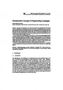


![FREE [DOWNLOAD] CONCEPTS OF PROGRAMMING LANGUAGES ...](https://m.moam.info/img/260x300/free-download-concepts-of-programming-languages-_647766e0097c47a9708bab98.jpg)
