ment (VIED) fund and that of the European Union's Seventh Framework. Programme (FP7/2007-2013) under the auspices of the CONCERTO project.
IEEE TRANSACTIONS ON WIRELESS COMMUNICATIONS, ACCEPTED FOR PUBLICATION
1
Irregular Convolution and Unity-Rate Coded Network-Coding for Cooperative Multi-User Communications Hung Viet Nguyen, Soon Xin Ng, and Lajos Hanzo
Abstract—Near-Capacity Multi-user Network-coding (NCMN) based systems operating in multiple modes and relying on an amalgamated Irregular Convolutional Code, a Unity-Rate Code and M-ary Phase-Shift Keying are proposed. We consider a multiuser network in which the users cooperatively transmit their independent information to a common base station (BS). Extrinsic Information Transfer (EXIT) charts were used for designing the proposed NCMN scheme for the sake of approaching the Discrete-input Continuous-output Memoryless Channel’s (DCMC) capacity. The NCMN systems are capable of simultaneously exploiting the advantages of all the new modes we designed for our system and those of the conventional mode. The design principles presented in this contribution can be extended to a vast range of NCMN based systems using arbitrary channel coding schemes. Index Terms—
I. I NTRODUCTION
N
ETWORK coding is a recent data transport paradigm [2], [3] that was introduced from an informationtheoretic perspective in [4]. Since then, network coding has penetrated various fields, including channel coding, wireless communications, computer networks, switching theory, cryptography, data storage and computer science [2], [5]. Network coding [4] has been shown to be capable of increasing the achievable throughput, while minimising both the amount of energy by optimising the allocation of the transmit power of each user [6] as well as delay of packets travelling through the network employing rateless random network codes [7]. Dynamic Network Codes (DNC) were proposed by Xiao et al. [8]–[11], where each of the M users broadcasts a single Information Frame (IF) of its own both to the Base Station (BS) and to the other users during the first Time Slot (TS). Then, during the 2nd to the (M )th TS, each user transmits to the BS (M − 1) nonbinary linear combinations of those particular IFs that were successfully decoded. Manuscript received April 26, 2012; revised September 26, 2012; accepted November 25, 2012. The associate editor coordinating the review of this paper and approving it for publication was N. Devroye. The authors are with the School of ECS, University of Southampton, SO17 1BJ, UK (e-mail: {hvn08r, sxn, lh}@ecs.soton.ac.uk). The financial support of the Vietnamese International Education Development (VIED) fund and that of the European Union’s Seventh Framework Programme (FP7/2007-2013) under the auspices of the CONCERTO project (grant agreement no 288502) is gratefully acknowledged. Part of this work was presented at VTC2011-Fall [1]. Digital Object Identifier 10.1109/TWC.2012.12.120587
Generalised Dynamic Network Codes (GDNC) were proposed in [12], [13] by interpreting the design problem as being equivalent to that of designing linear block codes defined over GF(q) for erasure correction. The authors of [12], [13] extended the original Dynamic Network Code (DNC) concept presented in [9]–[11] by allowing each user to broadcast several IFs (as opposed to a single IF in [9]–[11]) IFs of its own during the Broadcast Phase (BP) via orthogonal channels, as well as to transmit several nonbinary linear combinations, which are also considered as Parity Frames (PFs), during the Cooperative Phase (CP) via orthogonal channels. T¨uchler and Hagenauer proposed the employment of Irregular Convolutional Codes (IrCCs) [14], [15] for serially concatenated schemes, which are constituted by a family of convolutional codes having different rates, in order to design a near-capacity system. They were specifically designed with the aid of Extrinsic Information Transfer (EXIT) charts conceived for analysing the convergence properties of iterative decoding aided concatenated coding schemes [16]. As a further advance, it was shown in [17] that a recursive Unity-Rate Code (URC) having an infinite impulse response is capable of efficiently spreading the available extrinsic information across the entire iterative receiver chain. This URC may be employed as an intermediate code, in order to improve the attainable decoding convergence. The URC may be viewed as a precoder invoked for creating a serially concatenated inner code component having an infinite impulse response in order to reach the (1,1) point in the EXIT chart and hence to achieve an infinitesimally low Bit Error Ratio (BER) [18], as detailed in [19]. For example, a near-capacity Irregular Convolutional Coded (IrCC)-URC-M-ary Phase-Shift Keying (IrCC-URCMPSK) scheme may be designed for the sake of approaching the achievable channel capacity. Additionally, implementing iterative decoding exchanging extrinsic information between channel coding and network coding is capable of improving the system’s performance. This idea has been studied in [20], [21]. However, extending our knowledge acquired from [20], [21] to iterative decoding in the context of our scenario considering multiple-relays/users1 leads to an extremely high complexity, rendering the adoption of a joint channel-network code design impractical. This conclusion was also suggested by Iscan and Hausl in [22]. Alternatively, the inter-operation of channel- and network1 In our scenario, each user itself plays a role as a relay, hence our model has multiple-users and multiple-relays.
c 2012 IEEE 1536-1276/12$31.00 �
IEEE TRANSACTIONS ON WIRELESS COMMUNICATIONS, ACCEPTED FOR PUBLICATION
coding may be exploited to provide an improved performance, as suggested in [23]. We further develop this philosophy for the case of employing a practical near-capacity scheme, rather than an ideal/perfect capacity-approaching channel code. Furthermore, provided that reliable error detection is achieved, the random linear network coding regime of [24] can also be invoked for overcoming the quasi-static fading experienced by the system, in order to approach the attainable capacity, when the Galois field size of the network coding coefficients is sufficiently large. Against this background, the novel contribution of this article is that a practical near-capacity channel coding scheme is designed with the aid of EXIT charts for the sake of supporting cooperative communications employing our multimode network coding based system. More specifically: 1) A near-capacity coded modulation scheme is conceived for the proposed network-coding based system, in order to achieve a good performance. The near-capacity coded modulation scheme is designed with the aid of EXIT charts by considering both the effects of the quasi-static fading as well as of the small-scale Rayleigh fading in our channel model. 2) We formulated the complementary Cumulative Distribution Function (CDF) F (SN Rr |R ) of the SN R for characterising the Discrete-input Continuous-output Memoryless Channel (DCMC) employing MPSK. Based on F (SN Rr |R ), we defined and formulated the outage capacity of the coded modulation scheme corresponding to different outage probability values ε. This outage capacity is then employed for formulating the best-case performance bounds of both a single link as well as of our Near-Capacity Multi-user Network-coding (NCMN) based system. 3) Based on the upper bound and lower bound formulae conceived in [25] for a coherent Continuous-input Continuous-output Memoryless Channel (CCMC) based network coding aided system, we devise formulae for calculating the FER performance bounds and for quantifying the diversity order of the NCMN system operating in the conventional mode defined in [12], [13]. These bounds guide our network coding design as well as assist us in estimating the FER performance of the NCMN system without running extremely time-consuming MonteCarlo simulations. 4) The adaptive modes of our system are devised by appropriately adapting the philosophy suggested in [23] for our realistic coding scheme, in order to jointly treat channel coding and network coding. The performance bounds corresponding to the adaptive modes are also derived. 5) We propose to include the full-diversity mode for improving the attainable diversity gain of our system by extending the idea suggested in [26] for a network coding aided system relying on an idealised channel coding scheme operating exactly at the CCMC capacity. We then formulate the performance bound of the system operating in the full-diversity mode. 6) We also propose an additional random network coding layer in order to allow our system to have a three-layer
1.0 0.9 0.8
Outage Capacity/
2
0.7 0.6 0.5 0.4 0.3 0.2 0.1 0.0 -10
-5
. . .. . . .. .. .... .. .. .. .... .. ..... .. . . . . . . .. . 0
5
10
15
20
25
30
35
.
BPSK, QPSK, BPSK, QPSK, BPSK, QPSK, 40
45
-1
=10 -1 =10 -2 =10 -2 =10 -3 =10 -3 =10 50
SNR [dB]
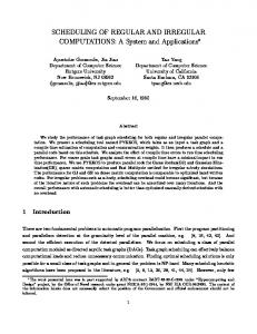
Fig. 1. Outage capacity of DCMC for the cases of employing the BPSK and the QPSK modulation schemes.
coding architecture, which may facilitate the further improvement of our system’s performance. 7) We introduced a novel family of multi-mode NCMNbased systems that is capable of simultaneously exploiting the advantages of all the modes available in our system. The rest of this article is organised as follows. The outage probabilities are derived for determining the outage capacity in Section II. Then, our system model is portrayed in Section III, detailing the coding layers as well as the operational principle of all of its modes. The bounds of the system’s outage probability corresponding to the various modes are derived in Section IV. In Section V, we present appropriate design procedures for both our near-capacity IrCC-URC-MPSK arrangement and for network coding. Our performance results are discussed in Section VI, before offering our conclusions in Section VII2 . II. P RELIMINARIES A. Outage Probability We consider a single transmission link associated with the transmitted and received signals of x and y, respectively. The received signal can be represented as y = hx + n ,
(1)
where h = hs hf is the complex-valued fading coefficient that comprises two components, a slow fading (or quasistatic fading) coefficient hs , which is constant for all symbols within a frame and a fast fading (small-scale Rayleigh fading) coefficient hf , which varies on a symbol by symbol basis. Finally, n is the Additive White Gaussian Noise (AWGN) process having a variance of N0 /2 per dimension. We refer to C as the maximum achievable transmission rate of reliable communication supported by this channel. Let us assume that the transmitter encodes data at a rate of R bits/s/Hz. If the channel realisation h has a capacity of C|h < R, the system is declared to be in outage, where the outage probability is given by: (2) Pe (R) = P r {C|h < R} , 2 The frequently used acronyms are NCMN (Near-Capacity Multi-user Network-coding), BS (Base Station), IF (Information Frame), PF (Parity Frame), BP (Broadcast Phase) and CP (Cooperative Phase).
NGUYEN et al.: IRREGULAR CONVOLUTION AND UNITY-RATE CODED NETWORK-CODING FOR COOPERATIVE MULTI-USER COMMUNICATIONS
N
3
2
1
1
2
N frames
Q
N
3
3
Q frames NET WO RK CODIN G 2 (NC2) To (From) M − 2 other Users
From Antenna
π
URC − 1
DEMOD
−1
IRCC − 1
π
Inner decoder
User f To
From
NC1
To
π
IRCC
MODulation
URC
NC1
User m
Antenna
User’s Unit
From Antenna
Fr om M Users
π− 1
URC − 1
DEMOD
π
Inner decoder
IRCC − 1
Base Station (BS)
To
NC1
Mode A : Convent ion
Mode A 1 : Adaptiv e 1
Mode F D : Full Diversity
Mode A 2 : Adaptiv e 2
Base Station CHANNEL CODIN G
Fig. 2.
NET WO RK CODIN G 1 (NC1)
The general architecture of the system.
and C|h is the channel capacity, provided that h is known. Furthermore, corresponding to the channel capacity C|h of (2), the maximum achievable transmission rate of reliable communication supported by the Discrete-input Continuous-output Memoryless Channel (DCMC) shown in [27] as: � was L � � L � � � 1 DCMC =η− E log2 exp(ψl,z )�� , (3) C(η) L l=1
z=1
Xl
where L = 2η is the number of modulation levels, while η is the number of modulated bits, and E [A|Xl ] is the expectation of A conditioned on the L-ary signals Xl , whereas ψl,z is a function of the transmitted signal and channel as defined in [27]. For the system relying on a single transmit and a single receiver antenna, it is given by � �2 −�h(xl − xz ) + n� + |n|2 , (4) ψl,z = N0 where h, x and n are the complex-valued fading coefficient, the transmitted signal and the AWGN, respectively. We define the receiver’s SN R as SN Rr = E[|h|2 SN R] = |hs |2 /N0 when E[|hf |2 ] = 1. At a given data rate R = ηRc , where Rc is the channel coding rate, we readily identify the corresponding SN Rr |R that is defined as the SNR value associated with the DCMC DCMC capacity C(η) = R on the C(η) -versus-SN R capacity curve represented by (3). Then, the outage probability of the DCMC model becomes equivalent to the probability of the specific event that we have |hs |2 SN R < SN Rr |R : � � SN Rr |R PeDCMC (R,η) = P r |hs |2 < . (5) SN R B. Outage Capacity In the slow fading channel, the outage capacity C(ε) introduced in [28] is defined as the highest possible rate of transmission R, while ensuring that the outage probability Pe remains less than ε. We define F (SN Rr |R ) as the
complementary cumulative distribution function of |h|2 = |hs |2 |hf |2 = |hs |2 , which is given by F (SN Rr |R ) =
� � SN Rr |R P r |hs |2 > . SN R
(6)
Note that F (SN Rr |R ) depends on the transmission rate R, and the corresponding SN Rr may then be calculated from (3). Similar to the formula established for the CCMC case in [28], it can be inferred from (5) that the SN R value associating with the outage capacity of the DCMC channel may be formulated as: SN R(ε, η) =
F −1 (1 − ε).
(7)
Hence the distribution function F (SN Rr |R ) can be used in conjunction with Equation (7) to calculate the outage capacity plotted in Fig. 1 corresponding to different outage probability values ε, namely to ε = 10−1 , 10−2 and 10−3 . III. S YSTEM M ODEL The general architecture of our system shown in Fig. 2 can be structured into three coding layers, namely Channel Coding, Network Coding 1 (NC1) and Network Coding 2 (NC2). In our three-layer coding system, N frames of a user’s information are processed in NC2, before feeding the Q resultant encoded frames to NC1. In the NC1 layer, M users cooperatively transmit M k1 IFs to the same destination node during a transmission session, where k1 is the number of IFs transmitted by each of the M users during the transmission session. Once the frames to be transmitted have been constructed according to the processes performed at NC1 and NC2, each of the frames is encoded by the channel coding scheme, as shown in Fig. 2.
4
IEEE TRANSACTIONS ON WIRELESS COMMUNICATIONS, ACCEPTED FOR PUBLICATION
(2 I2
U2
U2 (B 1 ) Broadcast phase 2
U2
U2
BS
(C 2 ) Cooperati ve phase 2
(C 1 ) Cooperati ve phase 1
BS
(C 3 ) Cooperati ve phase 3
= 7I
1 (1 )
+ 6I 2 (2 )
BS
M̂2(2 )
M̂2(2) = 7 I 1 (1) + 6I 2 (2)
+ 4I 2 (2 ) 1 (1 )
)
) 3I 2(2
= 5I
(1 ) + = I1
M̂2(1) = 5 I 1 (1) + 4I 2 (2)
U1
U1 ) M̂1(2
I 2 (2)
BS
M̂1(2) = I 1 (1) + 3I 2 (2)
BS
) 2I 2(2
U1
(1 ) +
(B 1 ) Broadcast phases 1
= 3 I1
BS
U2
U1
U1
)
) M̂1(1
(1
M̂1(1) = 3 I 1 (1) + 2I 2 (2)
I 1 (1)
I1
M̂2(1 )
U1
U2 (C 4 ) Cooperati ve phase 4
Fig. 3. Model of NC1 exploiting M = 2 users where each user transmits k1 = 1 IF and k2 = 2 PFs.
A. Network Coding 1, NC1 Our NC1 portrayed in Fig. 2 is capable of operating in various regimes, which are determined by activating an appropriately selected set of the following four modes: • The Conventional (C) mode is used for the default operation of NC1. • The Full Diversity (F D) mode can be activated for improving the system’s diversity gain. • Two adaptive modes, namely modes A1 and A2 , can be chosen for improving the multiplexing gain of the system. 1) The conventional mode, C mode: In our example depicted in Fig. 3, each of the M = 2 users transmits k1 = 1 IF during M k1 = 2 broadcast phases (B1 and B2 ) and k2 = 2 PFs during M k2 = 4 cooperative phases (C1 , C2 , C3 and C4 ), respectively. If we denote an IF transmitted by User m as Im (t), t = [m, M + m, ..., (k1 − 1)M + m], which takes place during the specific broadcast phase t, t = [m, M + m, ..., (k1 − 1)M + m], the arrangement of the BPs and CPs in Fig. 3 can be summarised as follows: I1 (1)
I1 (1)
(=0)
(=0)
I2 (2)
I2 (2)
(=0)
(=0)
(B1 U2 ) : U1 −−−→ U2 , (B1 B) : U1 −−−→ BS, (B2 U1 ) : U2 −−−→ U1 , (B2 B) : U2 −−−→ BS, �1(1)=3I1 (1)+2I2 (2)
(C1 U2 ) : U1 −−−−−−−−−−−−−− → U2 , (=1)
�1(1)=3I1 (1)+2I2 (2)
(C1 B) : U1 −−−−−−−−−−−−−−→ BS, (=1)
�2(1)=5I1 (1)+4I2 (2)
(C2 U1 ) : U2 −−−−−−−−−−−−−− → U1 , (=1)
�2(1)=5I1 (1)+4I2 (2)
(C2 B) : U2 −−−−−−−−−−−−−−→ BS, (=0)
�1(2)=I1 (1)+3I2 (2)
(C3 U2 ) : U1 −−−−−−−−−−−−−→ U2 , (=0)
�1(2)=I1 (1)+3I2 (2)
(C3 B) : U1 −−−−−−−−−−−−−→ BS, (=1)
�2(2)=7I1 (1)+6I2 (2)
(C4 U1 ) : U2 −−−−−−−−−−−−−−→ U1 . (=0)
�2(2)=7I1 (1)+6I2 (2)
(C4 B) : U2 −−−−−−−−−−−−−−→ BS. (=0)
(8) (9) (10) (11) (12) (13) (14) (15)
direction, while the variable �3 i(j) seen in Fig. 3 represents the j th PF of User i. Applying our convention used in [25], if all the frames transmitted in a session are successfully received at both the M = 2 users and the BS, then the transmission session can be described by the following transfer matrix [13]: � 1 0 | 3 5 1 7 . (18) G2×6 = 0 1 | 2 4 3 6 Note that the transfer matrix G2×6 is constructed from the generator matrix of Reed Solomon (RS) code formed over the Galois Field GF (8). Please refer to [13] for more specifics of � the transfer matrix. We then define G2×6 as the corresponding modified transfer matrix, where the terminology modified � implies that the entries of G2×6 are modified with respect to those of the original transfer matrix G2×6 of (18) according to the success/failure of each transmission phase within an actual transmission session. Note that the notation ‘(= 0)’ (or ‘(= 1)’) below the arrows of (8)-(17) indicates that the frame was unsuccessfully (or successfully) recovered at the receiver. According to the example of the transmission session given � by (8)-(17), the entries of G2×6 can be calculated by applying the general principles detailed in [25], in order to obtain the � modified matrix G2×6 as: � � 0 0 | 3 0 1 0 G2×6 = . (19) 0 0 | 0 0 0 0 Let us now generalise the above-mentioned example. The transfer matrix Gk1 M×(k1 M+k2 M) (or G for shorthand), which comprises the identity matrix Ik1 M×k1 M (or I for shorthand) and the parity matrix Pk1 M×k2 M (or P for shorthand), represents a transmission session of the system, where all the frames transmitted during that session are successfully decoded. We also � define the modified transfer matrix � Gk1 M×(k1 M+k2 M) (or G for shorthand) representing an actual transmission session. Note that the corresponding identity ma� � trix I of matrix G represents the results of the transmissions of the M k1 IFs sent by the M users to the BS during the k1 M broadcast phases.� By contrast, the corresponding parity matrix � P of matrix G illustrates the results of all the inter-user transmissions during the k1 M broadcast phases as well as the transmission results of all PFs transmitted from the M users to the BS during the k2 M cooperative phases. For the sake of brevity, please refer to� [25] for the generalised formulation of the matrices G and G as well� as for the recovery procedures of IFs at the BS relying on G . Accordingly, the NC1 information rate Rinf o is expressed as [12], [13] Rinf o
(16) (17)
Note that Bk U (or Bk B) represents a user-to-User transmission (or a user-to-BS transmission) during the broadcast phase Bk , while Cl U (or Cl B) indicates a user-to-User transmission (or a user-to-BS transmission) during the cooperative phase Cl . Additionally, the arrow ’−→’ represents the transmission
=
k1 . k1 + k2
(20)
2) The Full-Diversity mode, F D mode: It is worth noting that the transmissions in (C1 U2 ) of (10) (C2 U1 ) of (12), (C3 U2 ) of (14) and (C4 U1 ) of (16) are not employed in the C mode. If a network coding decoder is invoked by each of the M users, the cooperative transmissions, namely (C1 U2 ) of (10) (C2 U1 ) of (12), (C3 U2 ) of (14) and (C4 U1 ) of (16), 3 The
� operation in this context was first introduced in [9], [10].
NGUYEN et al.: IRREGULAR CONVOLUTION AND UNITY-RATE CODED NETWORK-CODING FOR COOPERATIVE MULTI-USER COMMUNICATIONS
can be exploited for recovering the erroneous frames that were corrupted by the outage of the inter-user channels during BPs as follows. • Cooperative Phase 1, when (C1 U2 ) is exploited. Ac� cordingly, the entries of the modified matrix GU2 ,2×6,C1 generated for transmissions from U1 to U2 at the end of phase (C1 U2 ) can be calculated by applying the general � algorithm detailed in [25], in order to obtain GU2 ,2×6,C1 as: � � 0 0 | 3 0 0 0 GU2 ,2×6,C1 = . (21) 0 1 | 0 0 0 0 �
By relying on GU2 ,2×6,C1 , U2 can now recover I1 (1) that could not be recovered owing to the outage occurring on (B1 U ). Note that after decoding all the frames received by the end of (C1 U2 ), U2 has already acquired the comprehensive knowledge of all the IFs, namely of I1 (1) and I2 (2). Hence, no further detection is needed at U2 . The above-mentioned comprehensive knowledge is then used for constructing the subsequent PFs transmitted by U2 during the subsequent CPs, namely during (C2 U1 ) and (C4 U1 ). Let us denote the knowledge of U2 about all IFs transmitted within the transmission session considered by Υ2 (ΓIF ), where ΓIF = {I1 (1), I2 (2)} represents all the IFs transmitted within the transmission session. As a result, U2 acquired a comprehensive knowledge of all two IFs as: Υ2 (ΓIF ) =
{I1 (1), I2 (2)} .
(22)
If (C1 U2 ) were not exploited at U2 , the corresponding � modified matrix GU2 ,2×6 generated for transmissions to U2 would be represented by: � � 0 0 | 0 0 0 0 GU2 ,2×6 = . (23) 0 1 | 0 0 0 0 �
Relying on the modified matrix GU2 ,2×6 , U2 would only be capable of recovering its own IF I2 (2). This would lead to the partial knowledge of U2 as: Υ2 (ΓIF ) =
•
{I2 (2)} .
(24)
It can be readily inferred from (22) and (24) that the exploiting network decoder at each user can assist in improving the inter-user transmissions degraded by outages encountered during the BPs. Cooperative phase 2, when (C2 U1 ) is taken into consideration. Similar to the above-presented process� associating with (C1 U2 ) of (10), the modified matrix GU1 ,2×6,C2 invoked for all transmissions from U2 to U1 by the end of (C2 U1 ) in (12) is formulated as: � � 1 0 | 3 0 0 0 . (25) GU1 ,2×6,C2 = 0 0 | 0 4 0 0 �
After applying the detection process for GU1 ,2×6,C2 , the comprehensive knowledge Υ1 (ΓIF ) of all the IFs is perfectly acquired by U1 as: Υ1 (ΓIF ) =
{I1 (1), I2 (2)} .
(26)
5
With the result of the network-decoding process at both U1 and U2 in mind, we can now formulate the modified matrix � G2×6,F D for the ensuing transmissions to the BS as: � � 0 0 | 3 0 1 0 G2×6,F D = . (27) 0 0 | 0 0 3 0 �
As seen from the modified matrix G2×6,F D of (27), the BS is now in a position to recover all two IFs, namely I1 (1) and I2 (2), (as opposed to only I1 (1) in the C mode example, as � represented by the modified matrix G2×6 given by (19)). Let us now generalise the processes at each user operating in F D mode by firstly denoting Υl (ΓIF ) as the knowledge of User l about all IFs transmitted within a certain transmission session, where ΓIF = {I1 (1), I2 (2), ..., IM (k1 M )} represents the set of all the IFs in the transmission session, while Γl (b) denotes the IF transmitted by User l during the bth BP. Accordingly, the processes occurring at User l during M k2 CPs of a transmission session are represented by an algorithm having M k2 iterations, each of which is accomplished by conducting the following four sequences; � Sequence 1: Construct a modified transfer matrix G for all transmissions to User l in the system. �The guidance for formulating the modified transfer matrix G can be found in [25]. Sequence 2: Apply the principle of the frame recovery described in [25], in order to recover all detectable IFs of the (M − 1)k1 IFs; Sequence 3: Update the knowledge Υl (ΓIF ) of User l about all the (M − 1)k1 IFs; Sequence 4: Build a subsequent PF required to transmit in subsequently assigned CP by using the current knowledge Υl (ΓIF ) of User l. 3) The Adaptive modes, A1 mode and A2 mode: The multiplexing gain of NC1 can be increased by reducing the number of transmitted PFs. In line with [23], we assume that the BS is capable of sending back to the users a modest amount of information containing feedback flags. Then, the reduced number of PFs can be calculated by making use of the successful/unsuccessful IF feedback flags sent from the BS. More specifically, let us denote the number of PFs transmitted by User j in a transmission session by k2,j . It was suggested in [23] that in order to increase the achievable multiplexing gain, the value of k2,j has to be adaptively adjusted for each transmission session according to two potential approaches. In the first adaptive (A1 ) mode, the diversity gain remains unaltered, while the value of k2,j is adaptively adjusted as � 0 : If Δ = 1 k2,j = , (28) k2 : Otherwise where the feedback flag Δ is an acknowledgement bit sent by the BS to indicate the successful/unsuccessful reception of all the M k1 IFs transmitted by all the M users during their BPs. The value of Δ obeys the following rule: � 1 : If M k1 IFs successfully decoded . (29) Δ= 0 : Otherwise In the second adaptive (A2 ) mode, the minimum diversity order of DN CMN = (M + k2 ) is guaranteed, while the value
6
of k2,j is adaptively adjusted as ⎧
M ⎨ 0 : If j=1 Λj = 1 k2,j = 1 : Else if Λj = 1 ⎩ k2 : Otherwise
IEEE TRANSACTIONS ON WIRELESS COMMUNICATIONS, ACCEPTED FOR PUBLICATION
,
(30)
where the feedback flag Λj is an acknowledgement bit sent by the BS to indicate the successful/unsuccessful reception of all the k1 IFs transmitted by User j during his/her BPs. The value of Λj can be specified as: � 1 : If k1 IFs successfully decoded Λj = . (31) 0 : Otherwise B. Near-capacity Channel Coding In the channel coding layer as shown in Fig. 2, we assume that all the links in the system are supported by channels having the same information rate R. In order to achieve an infinitesimally low BER, turbo detection may be employed at both the User’s unit and the BS. Therefore, a recursive URC [17] having an infinite impulse response may be employed as an intermediate code, as seen in the channel coding section of Fig. 2. If the User’s unit and the BS can afford the decoding complexity imposed by a near-capacity IrCC scheme, then a near-capacity performance may be achieved by employing the three-stage coding arrangement IrCC-URC-MPSK. In order to exploit the benefits of the turbo principle, an interleaver (π) is employed for efficiently spreading the extrinsic information in support of the inner iterations occurring between the intrinsically amalgamated URC-MPSK decoder and the IrCC decoder. In contrast to the IrCC-URC-MPSK scheme of [1] employing a 17-component IrCC code, a more powerful IrCC having 36 component codes is used in our system. As a benefit of having the 36-component-IrCC code, the 36-componentIrCC outer code is capable of achieving an improved matching to the EXIT curve of the intrinsically amalgamated inner URC-MPSK coding arrangement. Hence, our channel coding scheme, namely the IrCC-URC-MPSK scheme, is capable of approaching more closely to the DCMC capacity than the 17component scheme. C. Network Coding 2, NC2 In order to enhance the reliability of our system, NC2 may be activated for forming the three-layer coding architecture depicted in Fig. 2. In the NC2 layer, a random network code [24] is applied across the N IFs, namely across I1 , ...IN , in order to generate the Q network-coded frames of Z1 , ..., ZQ , where Q ≥ N . As a result, a linear combination of the N IFs having a length �N of LF bits each forms a network-coded frame Zj , Zj = i=1 αij Ii , where scalars αij (i ∈ [i, ..., N ] and j ∈ [1, ..., Q]) may be chosen randomly and uniformly from a GF (2q ). If the GF (2q ) is sufficiently large, the expected number of successfully received frames required by the BS for successfully decoding the N IFs is approximately N [24], [29]. Thereafter, we assume that the reception of N networkcoded frames at the BS is sufficient for the BS to recover N corresponding IFs. Accordingly, we define the conventional information rate of NC2 as: N . (32) Rinf o2 = Q
Once NC2 is activated in our system, the reception of N coded frames at the BS is sufficient for it to recover N IFs. Hence, an outage is declared, when the number of frames received at the BS is less than N , and this outage occurs with the probability of: PoN C2
=
N −1 � � i=0
� Q (1 − Po )i PoQ−i , i
(33)
where Po is the outage probability of the system when NC2 is not in operation.
D. System’s Parameters Our system can be characterised by using the set of main parameters: (R, M, k1 , k2 , G, N, Q, DN CMN ). Accordingly, the system’s overall information rate RN CMN is calculated by: RN CMN = Rinf o2 Rinf o R =
k1 RN . (k1 + k2 )Q
(34)
It should be noted that the value of Rinf o is duly changed when different modes are activated. We then define Eb /N0 as the energy per bit to noise power spectral density ratio, which can be computed as: Eb /N0 =
SN R (k1 + k2 )Q . = SN R RN CMN k1 RN
(35)
According to [9]–[13], the diversity order DN CMN of the system without N C2 is bounded by M + k2 ≤ DN CMN ≤ M k2 + 1.
(36)
The authors of [9]–[13] inferred the diversity order of DN CMN given in (36) based on the following formula: DN CMN =
lim
SN R→∞
− log2 Po , log2 SN R
(37)
where the order of Pe for the best-and worst-case Po value was estimated and used instead of Po itself, whereas Pe is the outage probability of a single link in the system. Furthermore, by exploiting the most influential terms of the upper- and lower-bounds instead of Po itself in (37), it may be seen that the upper- and lower-bounds derived in Section IV are in harmony with the estimated diversity order given by (36). In order to facilitate the illustration of the system design in the following sections, the key parameters of the system are briefly summarised in Table I.
IV. B OUNDS OF T HE S YSTEM ’ S O UTAGE P ROBABILITY In this section, we will derive the bounds of the system’s outage probability in different modes described in Section III, in order to estimate the approximate performance of the NCMN system without performing time-consuming MonteCarlo simulations.
NGUYEN et al.: IRREGULAR CONVOLUTION AND UNITY-RATE CODED NETWORK-CODING FOR COOPERATIVE MULTI-USER COMMUNICATIONS
TABLE I T HE MAIN PARAMETERS OF THE SYSTEM . Parameters R [BPS]
Description Information rate in Bit Per Symbol (BPS) for all the links in the system
Rc
The code rate of IrCC encoder
J [iteration] L [bit]
The number of iterations The frame length at the channel code layer
M [user] k1 [frame] k2 [frame]
The number of users The number of IF transmitted by each user
correctly recover the IF Im (t) is higher than or equal to the actual number of users ||Um,t ||. Thus, we have: ∗,F D FD FD ||Um,t || ≥ ||Um,t ||, ||Um,t || = M − ||Um,t ||,
Original transfer matrix
Rinf o [BPS]
The information rate of NC1
N [frame]
The number of uncoded frames
Q[frame]
The number of coded frames
Rinf o2 [BPS] RNCM N [BPS] DNCM N
The information rate of NC2 The system’s overall information rate Diversity order of the NC1-based system
(40)
∗,F D FD || is the complement set of ||Um,t ||. where ||Um,t Bearing (40) in mind, we may also follow the procedure of [25], in order to characterise the system’s performance bounds as:
P F D,Lower < PoF D < PoF D,Upper , � o �� � � �� � =PoC,Lower
The number of PF transmitted by each user
G
7
(41)
=PoC,U pper
where we define PoF D,Upper = PoC,Upper as the strict upper bound of the system’s outage probability PoF D , while PoF D,Lower = PoC,Lower is defined as the strict lower bound, while PoC,Upper and PoC,Lower are given in (38) and (39), respectively. It should be noted that the outage probability corresponding to the maximum (minimum) diversity order of (37) is employed for deriving the upper (lower) bound associated with the C mode and F D mode.
A. Conventional Mode: C
C. Adaptive Mode 1: A1
Let Um,t be the set of user indices corresponding to the specific users that succeeded in correctly recovering an IF Im (t) transmitted by User m during TS t. Note that User m itself is always included in this set. Let us denote the number of members in the user set Um,t by ||Um,t ||. Furthermore, ∗ let the complement set of Um,t be Um,t . We always have ∗ ||Um,t || = M − ||Um,t ||, 1 ≤ ||Um,t || ≤ M . Then, according to [9]–[12], there exist at least (k1 ||Um,t ||+k2 ||Um,t ||) frames, which contain the IFs transmitted by all the users in the set Um,t . Then, the strict upper bound PoC,Upper of the system’s outage probability PoC may be calculated by [25]: �� � �E+F �� M+k k1 +k2 −1 2 − F Pe (1 − Pe ) k 2 PoC,Upper = 1 − Pe − FE+1 Pe �E+F � M+k 2 Pe (1 − Pe ) 1 − RoM + F , (38) 1 − Ro 1 − Pe − FE+1 Pe
In can be readily inferred from (28) and (29) that none of the PFs are transmitted, when the BS already recovered all the IFs, while the same k2 PFs are transmitted otherwise. As a result, the diversity gain of the system remains unchanged. Hence, the system’s performance is only affected by the multiplexing gain defined as Ω1 , which can be calculated by:
where we have E = (M k1 − 1), F = M k2 and R0 = (1 − Pe )Pek2 −1 , provided that Pe is the outage� probability of the � single link as defined in [30]. Note that nk is the binomial coefficients. According to [25], the strict lower bound PoC,Lower can be calculated by: � �E+F � F +1 � Pe �E+1 E+1 P − (1 − P ) e e E+F F � � PoC,Lower = . Pe (1 − Pe )1−M E+F + Pe − 1 (39) B. Full Diversity: F D It should be noted that as a benefit of network coding used by each user unit, the outage of inter-channel transmissions encountered during the BPs is compensated, as illustrated by the numerical example of Section III. As a result, we may FD || of users that can argue that the equivalent number ||Um,t
=
Ω1
Rinf o,A1 . Rinf o
(42)
According to [23], the average network-coding rate Rinf o,A1 can be expressed as: Rinf o,A1 =
k1 � � . k1 + k2 1 − (1 − Pe )Mk1
(43)
Bearing in mind Rinf o = k1 /(k1 + k2 ) given by (20), we arrive at: Rinf o,A1 k + k2 � 1 � . Ω1 = = (44) Rinf o k1 + k2 1 − (1 − Pe )Mk1 Then, the upper bound PoA1 ,Upper and the lower bound of the system’s performance PoA1 can be computed as:
PoA1 ,Lower
Ω1 P C,Lower < Ω1 PoC < Ω1 PoC,Upper , � o�� � � �� � � �� � A ,Lower =Po 1
A =Po 1
(45)
A ,U pper =Po 1
where PoC,Upper and PoC,Lower are given in (38) and (39), respectively. D. Adaptive Mode 2: A2 In contrast to the A1 mode, it is suggested by (30) and (31) that upon introducing 0,1 or k2 PFs, an increased multiplexing gain can be achieved at the cost of a decreased diversity gain. Let us additionally define Dm,t = {dm,t , dm,t ∈ [1, ..., ||Um,t || − 1]} as a set of user indices belonging to Um,t except for User m, provided that all the
8
IEEE TRANSACTIONS ON WIRELESS COMMUNICATIONS, ACCEPTED FOR PUBLICATION
IFs transmitted by all users of Dm,t have been successfully recovered by the BS by the end of BPs. Bearing (30) and (31) in mind, there are at least Γ frames containing the IF transmitted by all the users of Um,t , where the value of Γ is specified by: Γ = ||Um,t ||(k1 + k2 ) + (1 − k2 )||Dm,t || .
where we define O = ||Um,t ||k1 − 1 and S = ||Um,t ||k2 . Having ||Um,t || − ||Dm,t || ≥ 1 [23] would lead to an A2 ∗ approximation of Γ , which would approximate Pm (Um,t ) given by (47) as: A2 ,S ∗ =Pm (Um,t ) � � ��� � O+S O O+i+2 � P e S+i A2 ∗ (Um,t ) ≥ , (48) Pm i+1−S i=0 (1 − Pe ) A2 ∗ (Um,t ) Pm
≤
i=0
k +||U
||+i
m,t Pe 2 (1−Pe )O−i
�−1 . �� O+k2 +||Um,t ||−1� k2 +||Um,t ||−1+i
�
��
A ,G
=Pm2
(49)
�
∗ ) (Um,t
However, there might be more than Γ frames [9], [10], [12], [13], which contain the IFs transmitted by all users of Um,t . If the availability of those extra frames is taken into account, we will have A2 ,Ac ∗ A2 ∗ (Um,t ) ≤ Pm (Um,t ), Pm
(50)
A2 ,Ac ∗ (Um,t ) is the actual probability of the outage where Pm A2 ,Ac ∗ (Um,t ) is for the information frame Im (t). Notably, Pm ∗ the outage probability for a given Um,t . The system’s outage ∗ probability PoA2 for all possible Um,t can be calculated by
=
P A2
M−1 �
∗ ||Um,t ||
Pe
A2 ,Ac ∗ Pm (Um,t ) ∗
∗ ||=0 ||Um,t
(1 − Pe )||Um,t ||−M+1
.
(51)
By focusing our attention on the region corresponding to a ∗ low Pe or small ||Um,t ||, (48) can be further approximated as P A2 >
∗ ||=0 PoA2 |||Um,t � �� �
(52)
A2 ,Ac ∗ ∗ ||=0 = when we take into account that Pm (Um,t )|||Um,t A2 ,S ∗ ∗ ||=0 . Additionally, upon substituting (49) Pm (Um,t )|||Um,t and (50) into (51), a further approximation can be derived ∗ as: M−1 A2 ,G ∗ � Pe||Um,t || Pm (Um,t ) A2 ≤ (53) P ∗ ||−M+1 . ||Um,t (1 − Pe ) ||U ∗ ||=0 m,t
Then, following a number of further steps commencing from (52) and (53), we arrive at:
where P
A2 ,L
is given by:
(55)
is calculated by: PeK (1−Pe ) O 1−Pe − K Pe
=
P A2 ,U
�� � k1 +k2 −1 k2
+
� ��−1 − O−1+K K−1 � � M
PeK (1−Pe ) O 1−Pe − K Pe
(Ro,A2 ) −1 Ro,A2 −1 �� ��−1 O+K−1 K−1
,
(56)
where we have Ro,A2 = 1 − Pe and K = k2 + M . Notably, the system’s performance is also affected by the multiplexing gain Ω2 defined as: Ω2
=
Rinf o,A2 . Rinf o
(57)
Since the average network-coding rate is Rinf o,A2 = k1 [23], we arrive at the k2 (k2 −1)(1−Pe )k1 k1 + −1 − −1 M k (M −1)k 1] [1−(1−Pe ) 1 ] [1−(1−Pe ) multiplexing gain Ω2 as: Ω2 =
k1 + k2 k1 +
k2 −1 [1−(1−Pe )M k1 ]
−
(k2 −1)(1−Pe )k1
[1−(1−Pe )
. (58)
(M −1)k1 −1
]
Then, the bounds of the system’s performance reflecting both the achievable diversity gain and multiplexing gain can be represented by Ω P A2 ,L < Ω2 P A2 < Ω2 P A2 ,U , � 2 �� � � �� � � �� �
A ,Lower =Po 2
A =Po 2
(59)
A ,U pper =Po 2
where PoA2 is the system’s outage probability when A2 is activated, while PoA2 ,Lower and PoA2 ,Upper are the corresponding lower and upper bounds of PoA2 , respectively. V. D ESIGN AND A NALYSIS In this section, the design guidelines of our system are discussed first. Then, a powerful channel coding scheme is designed for minimising the probability of errors imposed by link-level transmissions, which is followed by the analysis of both the attainable diversity gain and of the multiplexing gain of our system. A. System Design
,
A ,S ∗ )| ∗ ||=0 =(1−Pe )M −1 Pm2 (Um,t ||Um,t
P A2 ,L < P A2 < P A2 ,U ,
while P
A2 ,U
(46)
Accordingly, the outage probability for the information frame Im (t) may be calculated as: �O+S−||Dm,t ||k2 +||Dm,t ||� O � S−||Dm,t ||k2 +||Dm,t ||+i A2 ∗ , (47) Pm (Um,t ) = −||Um,t ||−i−1 i−Q (1 − Pe ) i=0 Pe
O �
P A2 ,L = PoC,Lower ,
(54)
As mentioned in [29], [31], the scalar of αij (i ∈ [i, ..., N ]) used in NC2 can be chosen from random coefficients defined over GF (28 ), which is sufficiently large for providing the Q virtually unlimited sets of αij , where the resultant Q sets of αij form Q vectors that are linearly independent of each other. According to [31], the coefficients αij may be obtained by obeying the constraints imposed by the specific structure of the Vandermonde matrix. Then, the coefficient matrix may be pregenerated and be stored by the users as well as by the BS for encoding and decoding. Accordingly, the users only transmit the indices of the coefficient sets employed for encoding the IFs to be transmitted to the other users or the BS, as part of the session setup information, before transmitting actual data. As a result, no overhead pertaining to the random coefficients is transmitted during the actual communications session. In
NGUYEN et al.: IRREGULAR CONVOLUTION AND UNITY-RATE CODED NETWORK-CODING FOR COOPERATIVE MULTI-USER COMMUNICATIONS
where matrix G4×8 and G6×12 are constructed over GF (8) and GF (16), respectively. Accordingly, the chosen parameters of the G4×8 -based system and the G6×12 -based system are listed in Table II. The G4×8 -based system and the G6×12 -based system are comparable, since they share the same parameter values of R = 1.0, M = 2 and Rinf o = 0.5. The systems employing G4×8 and G6×12 have a diversity order of 4 ≤ D4×8 ≤ 5 and 5 ≤ D6×12 ≤ 7, respectively. It is expected that the system possessing a higher diversity order exhibits a higher detection reliability, but may impose a higher detection complexity at the BS. B. Near-Capacity Channel Code Design As stated in Section I, a near-capacity IrCC-URC-MPSK channel coding scheme is chosen for the sake of approaching the achievable channel capacity. By apply the two-step principle that was used for 17-component IrCC codes in [1], the near-capacity IrCC-URC-MPSK channel coding scheme employing 36-component IrCC codes is designed. As a result, we obtain the EXIT curves in Fig. 4, where the corresponding
TABLE II T HE MAIN PARAMETERS OF THE NCMN SYSTEMS BASED ON THE G4×8 AND THE G6×12 . Parameters R[BPS]
G4×8 system
G6×12 system
1.0(QPSK)
1.0(QPSK)
Rc
0.5
0.5
J [iteration]
35
35
104 ,105 ,106
104 ,105 ,106
M [user]
2
2
k1 [frame]
2
3
k2 [frame]
2
3
G4×8
G6×12
L [bit]
G Rinf o [BPS] RNCM N [BPS] DNCM N
0.5
0.5
0.5(QPSK)
0.5(QPSK)
4 ≤ D4×8 ≤ 5
5 ≤ D6×12 ≤ 7
N
18
18
Q
20
20
1.0 0.9
.
0.7 0.6 0.5 0.4
... . . ... . . . ... . . ... . . ... . . ..
URC-QPSK,SNRr=2.3dB 36-component-IrCC Trajectory
0.8
IEURC-QPSK,IAIrCC
order to simply demonstrate the benefit of random network coding in the context of our system, we consider Q = 20, N = 18 and the fixed coding rate Rinf o2 = N/Q according to (32). By referring to the Rinf o expression of (20) and to the DN CMN formula of (36), we may conceive different systems having the same network coding rate Rinf o , but different diversity orders of DN CMN by independently adjusting k1 , k2 and M . In other words, using (34) and (36), we are able to design a network-coding based system having the highest possible diversity order at a given overall normalised data rate of RN CMN . A higher diversity order implies that the system is capable of achieving an improved FER performance. Based on the number of active users, a suitable transfer matrix is constructed from an appropriately chosen generator matrix of classic RS codes, which constitute maximum minimum distance codes. The generator matrix of RS codes constructed over the GF(q) is provided by the software application SAGE [32]. Again, the parameters characterising the system may be adjusted to meet diverse design criteria, such as the system’s effective information rate, or its expected FER-performance estimated on the basis of the system’s diversity order, etc. In order to highlight the generic design principles mentioned above, let us now consider a design example, where two specific systems, namely the G4×8 -based system and G6×12 based system, are taken into consideration. The matrix G4×8 and the matrix G6×12 ⎡ were provided by [12], ⎤ [13]: 1000 | 3736 ⎢ 0100 | 5774 ⎥ ⎥ (60) G4×8 = ⎢ ⎣ 0010 | 2461 ⎦ , 0001 | 5532 ⎡ ⎤ 1 0 0 0 0 0 | 11 2 4 6 14 12 ⎢ 0 1 0 0 0 0 | 1 11 13 10 14 10 ⎥ ⎢ ⎥ ⎢ 001000 | 2 4 2 10 5 9 ⎥ ⎥ G6×12 = ⎢ ⎢ 0 0 0 1 0 0 | 6 13 12 11 8 12 ⎥ , (61) ⎢ ⎥ ⎣ 000010 | 4 12 12 2 6 6 ⎦ 0 0 0 0 0 1 | 11 13 10 14 10 4
9
.. ...
..
.. . . . 0.2 .. Optimised Weighting Coefficients, [ ,..., ]= 0, 0, 0, 0.171, 0.355, 0, 0, 0.11, 0, 0, 0.198, ... [0, 0.1 .. 0.091, 0, 0, 0, 0, 0, 0, 0, 0, ... 0,0, 0,0, 0.032, 0, 0, 0, 0, 0, 0, 0, 0, 0, 0.040] 0.0 .
0.3
1
36
0.0 0.1 0.2 0.3 0.4 0.5 0.6 0.7 0.8 0.9 1.0
IAURC-QPSK,IEIrCC Fig. 4. The EXIT curves of the inner decoder URC-QPSK and the 36component-IrCC outer decoder for a single transmission link along with the Monte-Carlo simulation based decoding trajectory.
IrCC component-code weighting coefficients αi , i = 1, ..., 36 and the number of iterations of say J = 35 are shown. The Monte-Carlo simulation based FER and BER performance seen in Fig. 5 agrees with the prediction of our EXIT chart analysis. When employing J = 35 iterations between the IrCC and URC components, our IrCC-URC-QPSK channel coding scheme has a vanishingly low BER for SN Rs in excess of 2.3 dB, provided that the transmission frame length L is sufficiently high, such as L = 105 symbols. We hence opt for using the frame length of L = 105 symbols for all corresponding results from now on. Moreover, as seen in Fig. 5, the distance of γ = 0.5 dB from the DCMC capacity demonstrated that our 36-component-IrCC based coding arrangement outperforms the corresponding coding arrangement employing a 17-component IrCC code, which operates at a distance of γ = 1.0 dB from the corresponding DCMC capacity, as presented in [1]. For transmission over an uncorrelated Rayleigh fading channel, the transmitter can send data at the rate of R < C|h , while
10
IEEE TRANSACTIONS ON WIRELESS COMMUNICATIONS, ACCEPTED FOR PUBLICATION
......
1
-3
10
b
-4
C C MC ,R =1
10
B ER ,frame size =10 s ymbols 6 F ER ,frame size = 10 s ymbols 5 B ER ,frame size = 10 s ymbols 5 F ER ,frame size = 10 s ymbols 4 B ER ,frame size = 10 s ymbols 4 F ER ,frame size = 10 s ymbols C C MC ,R=1 DCMC-QP SK
-5
10
-6
10
0
6x12A1IrCC-URC-QPSK 6x12A2IrCC-URC-QPSK 6x12A1IrCC-URC-8PSK 6x12A2IrCC-URC-8PSK
1
0.9
.
b
b
2
.
3
SNR [dB ]
Fig. 5. Performance of the proposed IrCC-URC-QPSK scheme in an independently-fading Rayleigh channel.
Network Code Rate, Rinfo,A
BER/F ER
-2
10
1.0
6
DCMC -QP SK
.
-1
10
0.8
0.7
0.6 4x8,6x12 Conventional mode
0.5 4x8A1IrCC-URC-QPSK 4x8A2IrCC-URC-QPSK 4x8A1IrCC-URC-8PSK 4x8A2IrCC-URC-8PSK
0.4 7
8
9
10
11
12
13
14
15
16
17
SNR [dB]
maintaining an arbitrarily low error probability. However, this excellent performance cannot be maintained for quasi-static fading channels [28], where the channel coefficient is constant over the duration of a frame and varies independently from one frame to another. This flat Rayleigh fading channel will be referred to as a quasi-static Rayleigh fading channel for the sake of brevity. Accordingly, the performance of the proposed IrCC-URC-QPSK scheme recorded for transmission over the quasi-static Rayleigh fading channel is presented in Fig. 8 and Fig. 9 . Note that in Fig. 8 and Fig. 9, the FER performance corresponding to the equivalent outage capacity of both the IrCC-URC-QPSK arrangements is evaluated by calculating the outage capacity corresponding to a given range of outage probability, namely to ε = [10−1 , 10−4 ]. It can also be seen in Fig. 8 and Fig. 9 that the performance of the IrCC-URC-QPSK scheme communicating over the quasistatic Rayleigh fading channel and recorded for the frame length of L = 105 symbols is within about 0.4 dB apart from those of the corresponding outage capacity. C. Multiplexing and Diversity Enhancement in NC1 In the conventional scheme of [12], [13] as detailed in Section III-A1, the inter-user communications only take place during the BPs. By contrast, as illustrated by a specific example in Section III-A2 for the F D mode, a user may exploit the benefits of network coding and of the broadcast nature of wireless communications during both the BPs and CPs. Explicitly, the PFs transmitted during the CPs can be additionally detected by the other users, in order to improve the inter-user communications. The improved inter-user transmissions amongst the M users would result in an improved diversity gain for the system. More specifically, due to the broadcast nature of wireless communications, all users in the system are capable of listening to the PFs destined to the BS. Naturally, each of the M users has to be equipped with a network coding decoder for decoding the PFs with the aid of its own IFs and by additionally using the IFs successfully received from the other users during the BPs. As a benefit of the additional decoding process, each user becomes capable of compensating for not knowing the IFs transmitted from the other (M − 1) users, which is caused by outage of inter-user channels during the BPs.
Fig. 6. Network coding rate when the adaptive mechanism is applied in the system.
Having a full knowledge of the IFs of all the other users is the best scenario created by the F D mode. This best scenario is equivalent to the case, where all of the inter-user transmissions carried out during the BPs are successful. If this condition holds, our system always achieves its maximum diversity order given in [26] as: Max DN CMN
=
M k2 + 1.
(62)
Hence, the system’s performance associated with the idealised simplifying assumption of having perfect inter-user channels, where the inter-user channels are error free, sets a limit for the maximum attainable diversity gain of the nearfull-diversity process. In NC1, the adaptive network code rate Rinf o,A (either Rinf o,A1 or Rinf o,A2 ) may be calculated by Rinf o,A
= =
E[Number of IFs/session] , E[Number of frames/session] M k1 . M k1 + E[ΣM j=1 k2,j ]
(63)
The value of the adaptive network coding rate Rinf o,A given in (63) increases when the SN R increases as seen in Fig. 6. It can be also seen in Fig. 6 that the A2 mode can provide the improved network coding rate Rinf or,A2 in comparison to the Rinf or,A1 of the A1 mode. Furthermore, we can infer from (63) that the maximum value of the adaptive network coding rate can be calculated by: ! " M k1 Max {Rinf o,A } = Max , M k1 + E[ΣM j=1 k2,j ] = 1,
(64) E[ΣM j=1 k2,j ] of E[ΣM j=1 k2,j ]
approaches provided that the value of E[ΣM k ] = 0. The condition = 0 would j=1 2,j be satisfied, when PFs are no longer required to be transmitted to the BS, provided that a sufficiently high SN R value is experienced by our system. It can be readily inferred from (44), (58) and (64) that the maximum value of the multiplexing gains (Ω1 and Ω2 )
NGUYEN et al.: IRREGULAR CONVOLUTION AND UNITY-RATE CODED NETWORK-CODING FOR COOPERATIVE MULTI-USER COMMUNICATIONS
obtained by employing the adaptive feedback-flag based mechanism may be formulated as � � �� Rinf o,A � = Max 10 log [dB], Rinf o � � k1 + k2 [dB]. (65) = 10 log k1
Φ1 =
SN RC SN RC and Φ2 = , SN RA1 SN RA2
(66)
= Ω1 + Φ1 ,
(67)
where Ω1 and Φ1 are defined in (44) and (66), respectively. As a result of having a diversity gain of Φ1 = 0 for the A1 mode, the total-gain Σ1 is equal to the multiplexing gain Ω1 , as also seen in Fig 7. By contrast, introducing 0, 1 or k2 PFs in the CPs of the A2 mode detailed in (30) and (31) provides the improved multiplexing gain Ω2 seen in Fig. 7, which is also reflected by the network coding rate Rinf o,A2 plotted in Fig. 6. As seen in Fig. 7, although the system supported by the A2 mode has the higher multiplexing gain Ω2 , the overwhelming degradation4 of the related diversity gain Φ2 results in an inferior total gain of Σ2 , which is defined as: Σ2
= Ω2 + Φ2 ,
3 2
Gains
1 0
Multiplexing-Gain4 8,A1, IrCC-URC-QPSK Diversity-Gain4 8,A1, IrCC-URC-QPSK Total-Gain4 8,A1, IrCC-URC-QPSK
.
(68)
where Ω2 and Φ2 are defined in (58) and (66), respectively. Hence, it is expected that the system employing the A1 4 The degradation in multiplexing gain Φ is caused by introducing 0, 1 or 2 k2 PFs in the A2 mode, rather than employing 0 or k2 PFs in the A1 mode as detailed in (28)-(31).
..
..
.
.
.
.
.
.
.
.
..
. .
. .
-1 -2
Multiplexing-Gain4 8,A2, IrCC-URC-QPSK Diversity-Gain4 8,A2, IrCC-URC-QPSK Total-Gain4 8,A2, IrCC-URC-QPSK
.
-3 -4
4
6
8
10
12
14
SNR [dB] Fig. 7. The diversity-versus-multiplexing gain breakdown of the G4×8 based systems relying on the IrCC-URC-QPSK scheme, when considering both A1 mode and A2 modes.
.
-1
10
¤
5
¤
2
¤
.
.
-2
10
¤
5
5
. ¤
2
¤
-3
10
.
.
¤
-4
10
.
5 2 -5
8
NC14x8,C,SIMUL NC14x8, F D,SIMUL NC14x8,Perfect-inter,S IMUL NC14x8,C,Upper NC14x8,C,Lower 10
.
¤ ¤
¤ 12
NC14x8, A1,SIMUL NC14x8, A1,Upper NC14x8, A1,Lower NC14x8, A2,SIMUL NC14x8, A2,Upper NC14x8, A2,Lower
¤
.
¤
5
10
IrC C -URC -QPS K, L=10 6 IrC C -URC -QPS K, L=10 DCMC-QP SK
.
.
2
where SN RC , SN RA1 and SN RA1 denotes the SN R value required by the system using the C mode, A1 mode and A2 mode, respectively. It is worth noting that the SN RC , SN RA1 and SN RA2 corresponding to a specific F ER can be obtained with the aid of simulation results. In the system supported by the A1 mode, none of the PFs are transmitted, when the BS already recovered all the IFs, as detailed in (28) and (29). As a result, the F ER-versusSN R performance of the system remains unchanged at a given SN R value, when the A1 mode is applied. Hence, the diversity gain Φ1 corresponding to the system exploiting the A1 mode is Φ1 = 0, as seen in Fig 7. Let us define the totalgain Σ1 as the sum of the diversity gain and multiplexing gain in the case of employing the A1 mode, which can be formulated as: Σ1
4
F ER
max = 3 dB in our As a result, the maximum value is Ω1,2 configurations, where we have either k1 = k2 = 2 or k1 = k2 = 3 . Furthermore, as analysed in Section IV-C and Section IV-D, the attainable diversity gain may be characterised by the F ER-versus-SN R performance of the system, when the adaptive mode is employed. More specifically, if either the A1 or the A2 mode is activated in our system, the attainable FER-performance of the system associated with a given SN R value directly reflects the effects of decreasing the number of PFs, as described in (28)-(31). Therefore, let us define the diversity gain Φ1 and Φ2 achieved in our system by applying the A1 and A2 mode, respectively:
11
14
16
. 18
Eb /N0 [dB ] Fig. 8. FER performance in various configurations based on matrix G4×8 and the IrCC-URC-QPSK scheme and their corresponding bounds.
mode outperforms the system invoking the A2 mode in our investigations. VI. N UMERICAL R ESULTS AND D ISCUSSIONS The FER-performance curves seen in Fig. 8 substantiate that the system’s actual FER performance curves are always between their upper bound and lower bound. This suggested that the performance of NCMN systems can be characterised by the upper and lower bounds, rather than by extremely timeconsuming simulations. The convenience of using the bounds becomes particularly remarkable, when a large transfer matrix is employed. It is shown in Fig. 9 that the difference in the diversity order of the G4×8 and G6×12 based systems specified in Section V-A is demonstrated by the different slopes of the performance curves. Another important result gleaned from Fig. 9 and Fig. 10 is that the performance of the NCMN systems using the idealised/perfect DCMC channel coding schemes represents the best-case performance bound of all NCMN systems using realistic channel coding schemes, provided that those schemes employ the same modulation scheme as well as have the same equivalent data rate R. In addition, as seen in Fig. 9 and Fig. 10, the performance of G4×8 and G6×12 -based systems using our IrCC-URC-QPSK FEC scheme was merely within 0.5 dB from that of the corresponding systems relying on the assumption of using an idealised/perfect DCMC-QPSK capacity-achieving FEC channel coding scheme.
12
IEEE TRANSACTIONS ON WIRELESS COMMUNICATIONS, ACCEPTED FOR PUBLICATION -1
1
10
2
b b
-2
F ER
10
5
NC14x8,C NC14x8,C,DC MC NC16x12,C NC16x12,C,DC MC
b
. 5
.
IrC C -URC - QP SK , L =10 6 Ir C C -URC -QP SK , L =10 DCMC-QP SK
b 2
«
-3
10
b
2
5
¤
10
NC16x12, A1 NC26x12, A2 NC16x12,F D NC26x12,Perfect-inter NC16x12, F D+A1 NC16x12, F D+A2 NC16x12,Perfect-inter+A1 NC16x12,Perfect-inter+A2
5 2
-4
¤
-1
«
IrC C - URC -QPS K, L=10 , Eb N0 =42.5 dB at F ER=10
¤
¤ ¤ ¤
¤ ¤
¤
-2
10
5
NC218, 20,NC 14x8,C NC218, 20,NC 14x8,C,DC MC NC218,20,NC 16x12,C NC218, 20,NC 16x12,C,DC MC
¤ ¤
2 -3
5
10
«
5
b
2
b
«
-4
10
¤
5
F ER
5
11
12
2
NC218, 20 ,NC 14x8, F D+A1 NC218, 20 ,NC 14x8, F D+A2 NC218, 20,NC 16x12, F D+A1 NC218, 20 ,NC 16x12, F D+A2
¤ ¤
-4
13
Eb /N0 [dB ]
14
15
16
Fig. 9. FER performance of the G4×8 and G6×12 based system employing the IrCC-URC-QPSK scheme, in the scenarios employing the full-diversity mode and adaptive mechanism.
10
8.0
8.5
9.0
9.5
Eb /N0 [dB ]
10.0
10.5
Fig. 10. FER performance of the G4×8 and G6×12 based system employing the IrCC-URC-QPSK scheme, when NC2 is activated.
VII. C ONCLUSIONS As regards to the achievable diversity enhancement, the FER-performance curves of Fig. 8 and Fig. 9 substantiate our analysis provided both in Section III-A2 and in Section V-C, demonstrating that the FER-performance of system employing the F D mode is bounded by that of the idealised system relying on the simplifying assumption of error-free inter-user channels. The discrepancy is shown in Fig. 8 and Fig. 9 to be within 0.1 dB at an F ER of 10−4 . As regards to the achievable multiplexing gain analysed in Section V-C, it is seen in Fig. 8 and Fig. 9 that the adaptive modes are capable of providing a significant Eb /N0 performance improvement in comparison to that of the system operating in the C mode. For instance, an Eb /N0 performance improvement of 2.3 dB and 1.6 dB is recorded at an F ER = 10−5 , when applying the A1 mode and A2 mode of the G4×8 -based system, respectively. The attainable Eb /N0 improvement increases upon increasing the Eb /N0 value and 2 ) = 3 dB, when the reaches its maximum of � = 10log( k1k+k 1 Eb /N0 value becomes sufficiently high, as suggested by our analysis in Section V-C. As analysed in Section V-C, although the less complex A1 mode exhibits a lower multiplexing gain, it is capable of assisting the system in achieving a better FER performance than the system employing the A2 mode, as seen in Fig. 9. This is because the superior multiplexing gain of the A2 mode fails to compensate for the diversity-gain loss caused by transmitting less PFs. This result is in line with the conclusions presented in [23]. Furthermore, the superior performance supported by the A1 mode remains undiminished, when the system activates simultaneously the adaptive mode (A1 or A2 ), the F D mode and the additional network code NC2, as seen in Fig. 9 and Fig. 10. As expected, upon combining our adaptive modes, namely A1 and A2 with the F D mode, the system’s performance can be increased further, as evidenced by Fig. 9 and Fig. 10. Moreover, the system’s performance is in fact significantly improved by employing the NC2. More specifically, as shown in Fig. 9 and Fig. 10, a significant FER versus Eb /N0 performance improvement of about 30.0 dB (34 dB) can be achieved at an FER of 10−4 by activating the most appropriate modes of our two-layer (three-layer) coding scheme.
In this contribution, we conceived novel Near-capacity Cooperative Network-coding aided Multi-user (NCMN) systems capable of operating in multi-modes relying on our 36component IrCC-URC-MPSK scheme. The achievable performance was benchmarked against that of the corresponding systems employing the idealised/perfect capacity-achieving FEC schemes assumed to be operating exactly at the DCMC capacity. EXIT charts were used to assist the design of NCMN systems. We also derived the performance bounds of the NCMN scheme for designing our network coding system and for estimating the system’s performance. The performance of our proposed schemes was within 0.3-0.5 dB from that of the corresponding systems relying on the assumption of using an idealised/perfect DCMC-MPSK capacity-achieving FEC scheme. The joint treatment of channel and network coding leads to the adaptive modes, which is capable of 2 ) providing a maximum multiplexing gain of � = 10log( k1k+k 1 dB, i.e � = 3 dB in the configurations considered. As an alternative method, applying the full-diversity mode in our system allows the system to operate as close as 0.1 dB from the ideal/perfect inter-channel regime, when compared at an F ER of 10−4 . As expected, by combining the adaptive mode and full-diversity mode in order to achieve both a multiplexing and diversity gain, our system’s performance was further improved in comparison to that of the system employing the individual modes, namely either the adaptive or the full-diversity mode. Our proposed triple-layer architecture appears to provide even further performance improvements. For example, an improvement of as much as 34 dB was recorded at an F ER = 10−4 , provided that always the most suitable regime was activated by our illustrative triple-layer coding arrangement. R EFERENCES [1] H. Nguyen, S. X. Ng, J. Rebelatto, Y. Li, and L. Hanzo, “Near-capacity network coding for cooperative multi-user communications,” in Proc. 2011 IEEE Vehicular Technology Conference – Fall, pp. 1–5. [2] S.-Y. Li, Q. Sun, and Z. Shao, “Linear network coding: theory and algorithms,” Proc. IEEE, vol. 99, pp. 372–387, Mar. 2011. [3] B. Li and Y. Wu, “Network coding,” Proc. IEEE, vol. 99, pp. 363–365, Mar. 2011. [4] R. Ahlswede, N. Cai, S.-Y. Li, and R. Yeung, “Network information flow,” IEEE Trans. Inf. Theory, vol. 46, pp. 1204–1216, July 2000. [5] R. Yeung, “Network coding: a historical perspective,” Proc. IEEE, vol. 99, pp. 366–371, Mar. 2011.
NGUYEN et al.: IRREGULAR CONVOLUTION AND UNITY-RATE CODED NETWORK-CODING FOR COOPERATIVE MULTI-USER COMMUNICATIONS
[6] M. Xiao and T. Aulin, “Energy-efficient network coding for the noisy channel network,” in Proc. 2006 IEEE International Symposium on Information Theory, pp. 778–782. [7] M. Xiao, M. Medard, and T. Aulin, “Cross-layer design of rateless random network codes for delay optimization,” IEEE Trans. Commun., vol. 59, pp. 3311–3322, Dec. 2011. [8] M. Xiao and T. Aulin, “Optimal decoding and performance analysis of a noisy channel network with network coding,” IEEE Trans. Commun., vol. 57, pp. 1402–1412, May 2009. [9] M. Xiao and M. Skoglund, “M-user cooperative wireless communications based on nonbinary network codes,” in Proc. 2009 IEEE Information Theory Workshop on Networking and Information Theory, pp. 316–320. [10] M. Xiao and M. Skoglund, “Design of network codes for multipleuser multiple-relay wireless networks,” in Proc. 2009 IEEE International Symposium on Information Theory, pp. 2562–2566. [11] M. Xiao and M. Skoglund, “Multiple-user cooperative communications based on linear network coding,” IEEE Trans. Commun., vol. 58, pp. 3345–3351, Dec. 2010. [12] J. L. Rebelatto, B. F. Uchˆoa-Filho, Y. Li, and B. Vucetic, “Generalized distributed network coding based on nonbinary linear block codes for multi-user cooperative communications,” in Proc. 2010 IEEE International Symposium on Information Theory, pp. 943–947. [13] J. Rebelatto, B. Uchoa Filho, Y. Li, and B. Vucetic, “Multi-user cooperative diversity through network coding based on classical coding theory,” IEEE Trans. Signal Process., vol. PP, no. 99, p. 1, 2011. [14] M.T¨ucher and J. Hagenauer, “Exit charts of irregular codes,” in Proc. 2002 Conference on Information Sciences and Systems. [15] M. Tuchler, “Design of serially concatenated systems depending on the block length,” IEEE Trans. Commun., vol. 52, pp. 209–218, Feb. 2004. [16] S. ten Brink, “Convergence behavior of iteratively decoded parallel concatenated codes,” IEEE Trans. Commun., vol. 49, pp. 1727–1737, Oct. 2001. [17] S. X. Ng, J. Wang, M. Tao, L.-L. Yang, and L. Hanzo, “Iteratively decoded variable length space-time coded modulation: code construction and convergence analysis,” IEEE Trans. Wireless Commun., vol. 6, pp. 1953–1963, May 2007. [18] R. Tee, R. G. Maunder, and L. Hanzo, “Exit-chart aided near-capacity irregular bit-interleaved coded modulation design,” IEEE Trans. Wireless Commun., vol. 8, pp. 32–37, Jan. 2009. [19] L. Hanzo, O. Alamri, M. E. Hajjar, and N. Wu, Near-Capacity MutiFunctional MIMO Systems. John Wiley and Sons, 2009. [20] R. Y. S. Tee, T. Nguyen, S. X. Ng, L.-L. Yang, and L. Hanzo, “Luby transform coding aided bit-interleaved coded modulation for the wireless internet,” in Proc. 2007 IEEE Vehicular Technology Conference – Fall, pp. 2025–2029. [21] T. Nguyen, M. El-Hajjar, L. Yang, and L. Hanzo, “A systematic Luby transform coded V-BLAST system,” in Proc. 2008 IEEE International Conference on Communications, pp. 775–779. [22] O. Iscan and C. Hausl, “Iterative network and channel decoding for the relay channel with multiple sources,” in Proc. 2011 IEEE Vehicular Technology Conference – Fall), pp. 1–5. [23] J. Rebelatto, B. Uchoa-Filho, Y. Li, and B. Vucetic, “Adaptive distributed network-channel coding,” IEEE Trans. Wireless Commun., vol. 10, pp. 2818–2822, Sep. 2011. [24] T. Ho, M. Medard, R. Koetter, D. Karger, M. Effros, J. Shi, and B. Leong, “A random linear network coding approach to multicast,” IEEE Trans. Inf. Theory, vol. 52, pp. 4413–4430, Oct. 2006. [25] H. V. Nguyen, S. X. Ng, and L. Hanzo, “Performance bounds of network coding aided cooperative multiuser systems,” IEEE Signal Process. Lett., vol. 18, pp. 435–438, July 2011. [26] J. L. Rebelatto, B. F. Uchoa-Filho, and D. Silva, “Full-diversity network coding for two-user cooperative communications,” in Proc. 2011 IEEE Information Theory Workshop, pp. 543–547. [27] S. X. Ng and L. Hanzo, “On the MIMO channel capacity of multidimensional signal sets,” IEEE Trans. Veh. Technol., vol. 55, pp. 528–536, Mar. 2006. [28] D. Tse and P. Viswanath, Fundamentals of Wireless Communications. Cambridge University Press, 2005. [29] B. Li and D. Niu, “Random network coding in peer-to-peer networks: from theory to practice,” Proc. IEEE, vol. 99, pp. 513–523, Mar. 2011. [30] J. Laneman, D. Tse, and G. Wornell, “Cooperative diversity in wireless
13
networks: efficient protocols and outage behavior,” IEEE Trans. Inf. Theory, vol. 50, pp. 3062–3080, Dec. 2004. [31] R. Kim, J. Jin, and B. Li, “Scattered random network coding for efficient transmission in multihop wireless networks,” IEEE Trans. Veh. Technol., vol. 60, pp. 2383–2389, June 2011. [32] SAGE, “Open source mathematics software,” Available: http://wwwsagemath.org/. Hung Viet Nguyen received the B.Eng. degree in Electronics & Telecommunications from Hanoi University of Science and Technology (HUST), Hanoi, Vietnam, in 1999 and his M.Eng. in Telecommunications from Asian Institute of Technology (AIT), Bangkok, Thailand, in 2002. Since 1999 he has been a lecturer at the Post & Telecommunications Institute of Technology (PTIT), Vietnam. He is currently working towards the Ph.D. degree in the Communications Group, School of Electronics and Computer Science, University of Southampton, UK, where he is involved in the European Union project known as OPTIMIX. His research interests include cooperative communications, channel coding and network coding. Dr Soon Xin Ng (S’99-M’03-SM’08) received the B.Eng. degree (First class) in electronics engineering and the Ph.D. degree in wireless communications from the University of Southampton, Southampton, U.K., in 1999 and 2002, respectively. From 2003 to 2006, he was a postdoctoral research fellow working on collaborative European research projects known as SCOUT, NEWCOM and PHOENIX. Since August 2006, he has been a member of academic staff in the School of Electronics and Computer Science, University of Southampton. He is involved in the OPTIMIX and CONCERTO European projects as well as the IU-ATC and UC4G projects. He is currently a senior lecturer at the University of Southampton. His research interests include adaptive coded modulation, coded modulation, channel coding, space-time coding, joint source and channel coding, iterative detection, OFDM, MIMO, cooperative communications, distributed coding, quantum error correction codes and joint wireless-and-optical-fiber communications. He has published over 150 papers and co-authored two John Wiley/IEEE Press books in this field. He is a senior member of the IEEE, a Chartered Engineer and a fellow of the Higher Education Academy in the UK. Lajos Hanzo FREng, FIEEE, FIET, Fellow of EURASIP, DSc received his degree in electronics in 1976 and his doctorate in 1983. In 2009 he was awarded the honorary doctorate “Doctor Honoris Causa” by the Technical University of Budapest. During his 35-year career in telecommunications he has held various research and academic posts in Hungary, Germany and the UK. Since 1986 he has been with the School of Electronics and Computer Science, University of Southampton, UK, where he holds the chair in telecommunications. He has successfully supervised about 80 PhD students, co-authored 20 John Wiley/IEEE Press books on mobile radio communications totalling in excess of 10,000 pages, published 1250+ research entries at IEEE Xplore, acted both as TPC and General Chair of IEEE conferences, presented keynote lectures and has been awarded a number of distinctions. Currently he is directing an academic research team, working on a range of research projects in the field of wireless multimedia communications sponsored by industry, the Engineering and Physical Sciences Research Council (EPSRC) UK, the European IST Programme and the Mobile Virtual Centre of Excellence (VCE), UK. He is an enthusiastic supporter of industrial and academic liaison and he offers a range of industrial courses. He is also a Governor of the IEEE VTS. Since 2008 he has been the Editor-in-Chief of the IEEE Press and since 2009 a Chaired Professor also at Tsinghua University, Beijing. For further information on research in progress and associated publications please refer to http://wwwmobile.ecs.soton.ac.uk