resources (time, frequency or spreading code). In NOMA systems, multiple users can be scheduled on the ... for multiuser MIMO-NOMA downlink systems, where the ...... [21] M. Grant and S. Boyd, âCVX: Matlab software for disciplined convex.
This article has been accepted for publication in a future issue of this journal, but has not been fully edited. Content may change prior to final publication. Citation information: DOI 10.1109/ACCESS.2017.2700018, IEEE Access 1
Joint Beamforming and Power Optimization with Iterative User Clustering for MISO-NOMA Systems Zhengxuan Liu, Lei Lei, Ningbo Zhang, Guixia Kang, and Symeon Chatzinotas
Abstract—In this paper, we minimize transmit power for multiple-input single-output and non-orthogonal multiple access systems. In our analysis, a large number of users are partitioned into multiple user clusters/pairs with small size and uniform power allocation across the clusters, and each cluster is associated with a beamforming vector. The considered optimization problem involves how to optimize beamforming vectors, power allocation and user clustering. Considering the high computational complexity in solving the whole problem, we decompose the problem into two parts, and design a joint algorithm to iteratively optimize them. Firstly, given a user partition, we formulate the beamforming and power allocation problem under a set of practical constraints. The problem is nonconvex. To tackle it, we reformulate, transform, and approximate the nonconvex problem to a quadratically constrained optimization problem, and develop a joint beamforming and power allocation algorithm based on semidefinite relaxation to solve it. Secondly, to address the issue of high complexity in obtaining the optimal clusters, we propose a low-complexity algorithm to efficiently identify a set of promising clusters, forming as a candidate user partition. Based on these two algorithms, we design an algorithmic framework to iteratively perform them and to improve performance. By the algorithm design, the produced user partition can be further improved in later iterations, in order to further reduce power consumption. Numerical results demonstrate that the performance of the proposed solution with iterative updates for user clustering, and joint beamforming and power allocation optimization outperforms that of previous schemes. Index Terms—Non-orthogonal multiple access, beamforming, semidefinite positive programming, user clustering.
I. I NTRODUCTION Non-orthogonal multiple access (NOMA) is considered as a promising technique for 5G systems due to its enhanced performance compared to orthogonal multiple access (OMA) [1]-[4]. In OMA systems, each user exclusively accesses radio resources (time, frequency or spreading code). In NOMA systems, multiple users can be scheduled on the same resource in the power domain. The interference among co-channel allocated users can be partially canceled by successive interference cancellation (SIC) at the receivers. It has been shown that NOMA can outperform OMA not only in terms of the sum rate but also in terms of each user’s individual rate [4]. To further improve system capacity, beamforming is applied to NOMA in multiple-input multiple-output (MIMO) systems [5]-[15]. Random beamforming was studied in MIMO-NOMA Z. Liu, N. Zhang and G. Kang are with the Key Laboratory of Universal Wireless Communications, Beijing University of Posts and Telecommunications, China (Emails: {liuzhengxuan, nbzhang, gxkang}@bupt.edu.cn). L. Lei and S. Chatzinotas are with the Interdisciplinary Centre for Security, Reliability and Trust (SnT), University of Luxembourg, Luxembourg ({lei.lei, symeon.chatzinotas}@uni.lu).
systems, and a weighted proportional fair-based power allocation was adopted in [5]. Due to its randomness, interference cannot be effectively canceled, which may result in limited performance improvement. In [6], the authors enhanced system capacity for multiple-input single-output NOMA (MISONOMA) systems by performing a serial optimizations with user clustering, power allocation and zero-forcing beamforming (ZFBF) in a separated manner. The ZFBF vector of each cluster is obtained by utilizing the strongest user’s channel gain of this cluster. The solution selected two users with high correlation and large difference in channel gains. Similarly, the authors of [7] proposed a method that ZFBF vectors can be obtained by using any user’s channel vector in each cluster, and then a user matching algorithm was proposed to choose another user for clustering. Different from [5]-[7], beamforming vector of each cluster was calculated by utilizing optimization beamforming algorithm based on majorization minimization method in [8], and fractional transmit power control (FTPC) which was a sub-optimal power allocation method was utilized to allocate power to all users. The authors of [9] investigated beamforming design and power allocation for multiuser MIMO-NOMA downlink systems, where the number of users is more than the number of transmit antennas. The beamforming vector of each cluster was obtained by using a new ZFBF technique, which considered the equivalent channel gain of all users in its cluster. The optimal power allocation proposed in [3] was utilized for intra-cluster power allocation. Moreover, they proposed user clustering algorithm based on channel gain correlations and differences of among users to maximize network throughput. In [10], the authors investigated the model of channel uncertainties for MISONOMA downlink systems. A robust beamforming design and power allocation are attained by decoupling the formulated nonconvex optimization problem into four optimization problems, and then the problem is solved by applying alternating optimization algorithm. In [11], a general MIMO framework for NOMA downlink and uplink transmission based on signal alignment was proposed to enhance the performance gains of NOMA, and the impact of fixed power allocation and cognitive radio inspired power allocation on the performance of MIMONOMA was studied as well. Note that in [5]-[11], each beam serves one cluster and all users in a cluster are scheduled in a NOMA manner. Differently, the works [12]-[15] studied that each beam serves only one user. In [12], an iterative algorithm based on concaveconvex procedure was proposed to obtain beamforming vectors of all users for maximizing sum rate. The broadcast messages are the superposition of all users’ signals. This
2169-3536 (c) 2016 IEEE. Translations and content mining are permitted for academic research only. Personal use is also permitted, but republication/redistribution requires IEEE permission. See http://www.ieee.org/publications_standards/publications/rights/index.html for more information.
This article has been accepted for publication in a future issue of this journal, but has not been fully edited. Content may change prior to final publication. Citation information: DOI 10.1109/ACCESS.2017.2700018, IEEE Access 2
scheme may result in higher computational complexity and error propagation of SIC if there are too many users in systems. In [13] and [14], the beamforming vector of each user is obtained by combining conventional ZFBF and their proposed beamforming algorithm for each cluster. The authors in [15] first employed ZF method to avoid mutual interference and information leakage among clusters, and then they proposed an alternating optimization method and a constrained concaveconvex procedure to obtain secure beamforming design and power allocation. The proposed schemes in [13]-[15] require that the number of transmit antennas is no less than the number of users. However, the radio front end has a complexity, size and price that scales with the number of antennas [16]. In general, the number of transmit antennas is limited. There may be many users in systems. In such case, the number of transmit antennas is possibly far less than that of users. This results that the methods proposed in [13]-[15] is not feasible. In addition, the works [5]-[10] focused on spectral efficiency improvement. The transmit power minimization problem with SINR constraints was considered in [13]-[14]. In [17], a power minimization problem for multi-carrier NOMA subject to individual user’s data requirement has been investigated. In multi-antenna NOMA systems, power allocation and beamforming, as well as user clustering are key factors for system performance in terms of power consumption. In previous studies, e.g., [5]-[9],[11], user clustering, power allocation and beamforming were typically considered separately. We observe that if joint optimization is considered, system performance can be further improved from two perspectives. One is joint beamforming and power allocation. Observing the expressions of signal-to-interference-plus-noise ratio (SINR), power allocation is affected by beamforming design, and vise versa. Hence, the mutual influence between beamforming and power allocation should be considered. On the other aspect, power and beamforming optimization largely depends on the decision of user clustering, i.e., which users are grouped into a cluster. Improper user clusters may result in either high power consumption or failures in SIC. If power and beamforming are based on proper user clusters and then optimized, the former can efficiently suppress intra-cluster interference, while the later can suppress inter-cluster interference. The powersaving performance can be therefore benefited from the joint optimization. In this paper, based on aforementioned considerations, we take into account all three key factors, i.e., beamforming design, power allocation and user clustering, in our optimization procedure. Considering the high computational complexity for jointly optimizing three factors to global optimum, the proposed algorithmic solution is simplified to two components, i.e., algorithm for user clustering, and algorithm for joint beamforming and power allocation. The two components are jointly and iteratively performed in an algorithmic framework. That is, once a user partition is produced, the joint beamforming and power optimization is then performed. By our design, the user partition can be improved in later iterations, followed by joint beamforming and power optimization at each iteration. Compared to previous works, e.g., [5]-[9], we provide more opportunities to search user clusters based on
different criteria, instead of producing only one user partition based on a single criterion, e.g., greedy selection for the users with the largest difference in channel gains. Thus, in this work, the overall power performance can be improved from the diverse selection in user clustering, and performing joint beamforming and power optimization. Specifically in our proposed algorithmic framework, for generating user clusters, we design a sub-optimal algorithm with low complexity. In order to solve the joint beamforming and power allocation for each given user partition, we first formulate the problem and conclude its non-convexity. We then derive an equivalent reformulation and approximately convert it to a convex problem. An joint power allocation and beamforming design algorithm is proposed based on semidefinite relaxation (SDR) technique. Numerical results demonstrate the proposed joint optimization and iterative algorithm is able to reduce power consumption, compared to previous schemes. The rest of this paper is organized as follows. Section II outlines system model. Problem formulation, the formulated problem transformation and proposed joint beamforming and power allocation algorithm are presented in Section III. Section IV gives the proposed iterative user clustering and joint beamforming and power allocation algorithm. The numerical results are provided in Section V. Finally, Section VI concludes the paper. Notation: Boldface uppercase and boldface lowercase letters denote matrices and column vectors, respectively. The symbols Cn and Rn+ are used for n-dimensional complex and nonnegative real spaces, respectively. CN (a, b) represents the distribution of circularly-symmetric complex Gaussian random H variable with mean a and covariance b. The superscript (·) denotes the Hermitian transpose operator. tr (·), rank (·), |·| and ∥·∥ denote the trace, the rank, the absolute value and the Euclidean norm operators, respectively. O (·) is reserved for complexity estimates. Let Xl ≽ 0 denote that X is a Hermitian positive-semidefinite matrix. A (m, n) represents (m-th and n-th) element of matrix A, A (m, :) and A (:, n) denote the m-th row elements and n-th column elements of matrix A, respectively. Finally, X \x denotes that x component is not included in the X set. II. S YSTEM M ODEL Consider a MISO-NOMA downlink system consisting of a base station (BS) with M antennas serves K users equipped with single antenna. Each beam serves a cluster consisting of two or more users. In order to reduce the system complexity, we follow the same settings as previous works [1], [11], that is, two users for each cluster. According to users’ channel strengths, denoted as the Euclidean norm of channel vectors, the two users are defined as near user and far user corresponding to stronger channel user and weaker channel user, respectively. Note that this definition is different from [11] and [13], in which one user close to the BS, denoted as near user and the other user is not, denoted as far user. Let L denote the number of clusters, and the clusters set is defined as L = {1, 2, . . . , L}. BS sends the following L × 1
2169-3536 (c) 2016 IEEE. Translations and content mining are permitted for academic research only. Personal use is also permitted, but republication/redistribution requires IEEE permission. See http://www.ieee.org/publications_standards/publications/rights/index.html for more information.
This article has been accepted for publication in a future issue of this journal, but has not been fully edited. Content may change prior to final publication. Citation information: DOI 10.1109/ACCESS.2017.2700018, IEEE Access 3
information-bearing vector √ √ 1 − λ1 x1,n + λ1 x1,f .. x= , . √ √ 1 − λL xL,n + λL xL,f
(1)
in which xl,n and xl,f , ∀l ∈ L denote the near user and far user’s signals with zero √ mean and unit √ variance in the l-th cluster, respectively, and 1 − λl and λl denote power allocation coefficients of the near user and far user of the l-th cluster. The receive signal for the k-th user of the l-th cluster can be represented as ˜ yl,k = hH l,k Wx + zl,k , ∀l ∈ L, k ∈ {n, f } ,
(2)
in which hl,k ∈ CM denotes user k channel vector in the ˜ = [w l-th cluster, W ˜ 1, . . . , w ˜ L ], and w ˜ l ∈ CM denotes the √ beamforming vector of the l-th cluster. Let w ˜ l = pl wl , in 2 which pl = ∥w ˜ l ∥ is the transmit power for the l-th cluster, and wl is normalized beamforming vector( of that ) cluster, i.e., ∥wl ∥ = 1. We assume that zl,k ∼ CN 0, σ 2 , l ∈ L, k ∈ {n, f } and channel state information is available at users and BS. According to the system model, all users have been partitioned into different clusters. At the far user of the l-th cluster, the receive signal can be represented by √ √ yl,f = hH 1 − λl xl,n + hH λl xl,f l,f wl l,f wl ) ∑ (√ √ +hH + +zl,f .(3) 1 − λ x λ x j j,n j j,f l,f j∈L\l
In (3), the first term is the intra-cluster interference caused by near user in the l-th cluster. The third term is inter-cluster interference which comes from other beams. Similarly, the receive signal for the near user of the l-th cluster is represented by √ √ yl,n = hH 1 − λl xl,n + hH λl xl,f l,n wl l,n wl ) ∑ (√ √ +hH + +zl,n .(4) 1 − λ x λ x j j,n j j,f l,n j∈L\l
Assume the decoding order is (f, n). At far user and near user receiver, the near user signal is considered as noise when decoding far user signal. Therefore, the SINRs of far user at far user and near user receiver in the l-th cluster are respectively expressed as 2 λl pl hH l,f wl SIN Rl,f = 2 2 ∑ H (1 − λl ) pl hH w + p w h + σ2 l j j l,f l,f j∈L\l
(5) and
2 λl pl hH wl l,n f SIN Rl,n = . 2 ∑ 2 H 2 (1 − λl ) pl hH w + p w +σ j hl,n j l,n l j∈L\l
(6) In NOMA systems, the SINR of far user should be equal to ( ) f min SIN Rl,f , SIN Rl,n so that the far user’s signal xl,f
has to be decodable at far user and near user’s receivers of the l-th cluster, and SIC can be carried out at near user in decoding xl,n . As described above, SIC can be implemented to cancel far user’s interference at near user receiver. Hence, near user can decode xl,n without interference from xl,f . The SINR of near user in the l-th cluster can be written as 2 (1 − λl ) pl hH w l l,n . (7) SIN Rl,n = ∑ 2 H 2 pj hl,n wj + σ j∈L\l
Observing (5), (6) and (7), one can see that the SINRs of users are mainly decided by two factors: power allocation coefficient and beamforming vector. Different from [5]-[9] which optimize one factor in their formulated problems, we will optimize them together. In this paper, we focus on the total transmit power minimization subject to all users’ quality of service (QoS) requirements and ∥wl ∥ = 1, ∀l ∈ L. We consider that the power pl of each cluster is same as settings in [5]-[8], i.e, p = pl , ∀l ∈ L. III. J OINT B EAMFORMING D ESIGN AND P OWER A LLOCATION Given a user partition, we formulate the beamforming and power optimization problem in (8). We collect all the beamforming vectors w1 , . . . , wL and all power allocation coefficients λ1 , . . . , λL to w and λ, respectively. The optimizing variables are w, λ, and p. min
{w,λ,p}
p
(8a)
s.t. SIN Rl,n ≥ γl,n , ∀l ∈ L, ( ) f min SIN Rl,f SIN Rl,n ≥ γl,f , ∀l ∈ L, ∥wl ∥ = 1, ∀l ∈ L.
(8b) (8c) (8d)
In constraints (8b) and (8c), γl,n and γl,f are the target SINR threshold of the near user and the far user in the lth cluster, respectively. The optimization problem in (8) can be equivalently formulated as follows: min
{w,λ,p}
s.t.
p
(9a)
SIN Rl,n ≥ γl,n , ∀l ∈ L, SIN Rl,f ≥ γl,f , ∀l ∈ L,
(9b) (9c)
f SIN Rl,n ≥ γl,f , ∀l ∈ L,
(9d)
∥wl ∥ = 1, ∀l ∈ L.
(9e)
It can be observed that formulation (9), as well as formulation (8), is non-convex, due to non-linear and non-convex constraints (9b) ∼ (9d). This motivates us to pursuit an approximated solution instead of obtaining global optimal solution. In order to address (9), we first reformulate (9) to an equivalent problem, since the reformulated problem can be converted to a convex problem by using Taylor series expansion and SDR method. Then an iterative algorithm is proposed to obtain the power allocation and beamforming vector solutions in this section. The non-linear form of the
2169-3536 (c) 2016 IEEE. Translations and content mining are permitted for academic research only. Personal use is also permitted, but republication/redistribution requires IEEE permission. See http://www.ieee.org/publications_standards/publications/rights/index.html for more information.
This article has been accepted for publication in a future issue of this journal, but has not been fully edited. Content may change prior to final publication. Citation information: DOI 10.1109/ACCESS.2017.2700018, IEEE Access 4
coupled optimization variables is the main difficult in solving 1 problem (9). In order to tackle it, we first define αl = 1−λ , l 1 1 βl = λl and r = p , αl and βl denote the l-th component of the vector α and β, respectively. Then, we give the following proposition to transform original problem to an equivalent one. Proposition 1 The optimization problem in (9) can be equivalently expressed as (10). max r 2 hH l,n wl ≥ γl,n ul αl , ∀l ∈ L, 2 s.t. ∑ H hl,n wj ≤ ul − rσ 2 , ∀l ∈ L, {w,α,β,u,v,t,r}
(10a)
(10b)
j∈L\l
2 γl,f hH l,f wl ≥ 1+γl,f vl βl , ∀l ∈ L, 2 ∑ H hl,f wj ≤ vl − rσ 2 , ∀l ∈ L,
(10c)
j∈L
2 γl,f hH l,n wl ≥ 1+γl,f tl βl , ∀l ∈ L, 2 ∑ H hl,n wj ≤ tl − rσ 2 , ∀l ∈ L, j∈L
( )
αl − βl
≤ αl + βl − 2, ∀l ∈ L,
2 ∥wl ∥ = 1, ∀l ∈ L. where w ∈ C , u ∈ and r ∈ R+ . M
RL +, v
∈
RL +, t
∈
RL +, α
∈
RL +, β
(10d)
αl βl ≥ 0. Let αl + βl ≤ αl βl be divided by αl βl . We obtain 1 1 ∗ ∗ ∗ αl + βl ≤ 1. Let wl , αl , βl , ∀l ∈ L be the optimum solutions 1 1 of problem (10). If α∗ + β ∗ = 1, then wl∗ , λ∗l = β1∗ , ∀l ∈ L are l l l the optimum solutions of problem (9) since the same problem is solved with a change of variables. Otherwise, α1∗ + β1∗ < 1. l) l ( ) ( Let α ˜ ∗ = α∗ 1∗ + 1∗ and β˜∗ = β ∗ 1∗ + 1∗ such that l
1 α ˜∗ l
∈ RL +
Proof : Since r is in inverse proportion to p which is positive, the original minimum problem of p becomes the maximum problem of r. Let numerator and denominator of SIN Rl,n divide p. Then, (9b) is recasted as 2 H hl,n wl ≥ γl,n αl . (11) 2 ∑ H hl,n wj + rσ 2
2 H hl,n wl γl,f ≥ βl . 2 ∑ H (1 + γl,f ) hl,n wj + rσ 2
βl
l
l
αl
βl
l
in which the superscript c denotes the c-th iteration in the following proposed iteration algorithm. After this operation, the first set of constraints in (10b) becomes convex in the variables of interest. Similarly, the bilinear products on the right side of the first set of constraints (10c) and (10d) are respectively expressed as ( ) 2 2 ψ (vl , βl ) = vl βl = 0.25 (vl + βl ) − (vl − βl ) ( 2 2 (15) = 0.25(vl + βl ) − 0.25 (vlc − βlc ) +2 (vlc − βlc ) (vl − vlc − βl + βlc )) and
(12)
j∈L
and
αl
= 1 without violating SINR constraints (10b) ∼
+2 (ucl − αlc ) (ul − ucl − αl + αlc )) ,
j∈L\l
Similarly, (9c) and (9d) are respectively rewritten as H 2 hl,f wl γl,f βl ≥ 2 ∑ H (1 + γl,f ) hl,f wj + rσ 2
l
1 β˜∗
(10d) since α1∗ + β1∗ < 1. Furthermore, the objective value l l keeps invariable since the objective is only a function of p. Thus, the obtained optimum solutions wl∗ , α ˜ l∗ , β˜l∗ , ∀l ∈ L of ∗ ∗ problem (10) are the optimum ones wl , λl = β˜1∗ , ∀l ∈ L of l problem (9). Putting together all transformations above, we obtain the equivalent problem (10). � The first set of constraints in (10b), (10c) and (10d) is nonconvex because of the bilinear term on the right side. To make the problem become convex, we approximate them through a first order Taylor series around ucl , αlc as used in [12] since ul and αl are all nonnegative, i.e., ( ) 2 2 φ(ul , αl ) = ul αl = 0.25 (ul + αl ) − (ul − αl ) ( 2 2 (14) = 0.25(ul + αl ) − 0.25 (ucl − αlc )
(10e) (10f)
+
( ) 2 2 ϕ (tl , βl ) = tl βl = 0.25 (tl + βl ) − (tl − βl ) ( 2 2 = 0.25(tl + βl ) − 0.25 (tcl − βlc )
(16)
+2 (tcl − βlc ) (tl − tcl − βl + βlc )) . (13)
j∈L
To arrive at a tractable solution, we introduce additional slack variables ul , vl and tl such that the constraints of (11), (12) and (13) are transferred into (10b), (10c) and (10d), respectively. The variables ul , vl and tl are the l-th component of the vector u, v and t, respectively. Then, we adopt the similar method as proposed in Theorem 1 of [20] to prove that (10e) can be equivalently transformed by following process. The condition in (10e) implies that αl + βl ≤ αl βl . Observing the right-hand side of it, we know αl + βl ≥ 2. Hence,
After these transformations above, (10) becomes a quadratically constrained convex optimization problem, which is able to be solved by concave-convex procedure [12]. However, this method has a drawback that it needs a feasible point as initialization [18], which is difficult to obtain in general. SDR is a powerful, computationally efficient approximation technique for quadratically constrained optimization problem and widely used in the area of signal processing and communication [19][20]. Therefore, SDR approach is considered to solve (10). First, problem (10) is rewritten as the semidefinite positive (SDP) form, as shown in (17) by relaxing rank constraints on rank (Wl ) = 1, ∀l ∈ L, where Wl = wl wlH , after some
2169-3536 (c) 2016 IEEE. Translations and content mining are permitted for academic research only. Personal use is also permitted, but republication/redistribution requires IEEE permission. See http://www.ieee.org/publications_standards/publications/rights/index.html for more information.
This article has been accepted for publication in a future issue of this journal, but has not been fully edited. Content may change prior to final publication. Citation information: DOI 10.1109/ACCESS.2017.2700018, IEEE Access 5
basic operations and define Hl,k = hl,k hH l,k , k ∈ {n, f }. max r {{Wl }Ll=1 ,α,β,u,v,t,r} { tr∑ (Hl,n Wl ) ≥ γl,n φ(ul , αl ), ∀l ∈ L, s.t. tr (Hl,n Wj ) ≤ ul − rσ 2 , ∀l ∈ L,
(17a)
(17b)
j∈L\l
γl,f tr (Hl,f Wl ) ≥ 1+γ ψ (vl , βl ) , ∀l ∈ L, l,f ∑ 2 tr (H W ) ≤ v l,f j l − rσ , ∀l ∈ L, j∈L γl,f tr (Hl,n Wl ) ≥ 1+γ ϕ (tl , βl ) , ∀l ∈ L, l,f ∑ tr (H W ) ≤ t − rσ 2 , ∀l ∈ L, l,n j l
(17c)
(17d)
j∈L
tr (Wl ) = 1, ∀l ∈ L,
(17e)
Wl ≽ 0, (10e).
(17f) (17g)
We now conclude problem (17) is convex and can be effectively solved by convex optimization solver such as SeDuMi [21], which uses an interior point algorithm to efficiently find an optimum solution to the problem. Based on the derivation and analysis above, an iterative optimization algorithm is summarized as Algorithm 1 referred as Joint Beamforming and Power Allocation Algorithm (JBPA). Convergence Analysis: From Algorithm 1, it will be readily seen that the obtained optimal solution at the c-th iteration are also feasible for the problem at the iteration c + 1, which is due to the approximation (14) ∼ (16) [22]. This implies that Algorithm 1 returns a non-decreasing sequence of objective values, i.e., rc+1 ≥ rc . Moreover, according to the definition of the feasible set wl , ∀l ∈ L, α, β, u, v, t, r in (10), these optimization variables are convex and compact. This makes the algorithm converges to a finite value [12]. Following the proof of the Theorem 1 in [22], one can prove that the proposed algorithm converges to a Karush-Kuhn-Tucker point of problem (9). Due to the relaxation, the solutions of (17), denoted as Wl∗ , ∀l ∈ L may not be rank one. This is because the (convex) feasible set of problem (referred the rank-one relexation problem ) is a superset of the (nonconvex) feasible set of problem (referred the rank-one kept problem). In addition, the optimum objective value of problem (17) is merely a lower bound on the transmitted power required by the rank-one transmit beamforming scheme [23]. If Wl∗ , ∀l ∈ L contain only rank-1 matrices, then the principal component of each Wl∗ is the optimum beamforming vector for the l-th cluster. Otherwise, we use the randomization technique as applied in [23] and [24] to generate candidate solution of power allocation coefficients and beamforming vectors from Wl∗ , ∀l ∈ L and choose the one that yields the minimum transmit power solution among all feasible ones. A. Randomization Algorithm In this subsection, we develop a randomization algorithm to obtain an approximate solution to the original problem from the solution to its relaxed version if rank(Wl∗ )>1. The randomization algorithm is described as follows.
Algorithm 1 Joint Beamforming and Power Allocation Algorithm (JBPA) 1: Initialization: Set iteration index c = 0, maximum iteration number Cmax , and generate initial points (uc , vc , tc , αc , β c , rc ). Error tolerance ε ≪ 1. 2: repeat 3: c=c+1 4: Solve (17) with (uc−1 , vc−1 , tc−1 , αc−1 , β c−1 , rc−1 ) L and obtain the solution {Wl∗ }l=1 and ∗ ∗ ∗ ∗ ∗ ∗ (u , v , t , α , β , r ) . 5: Update uc = u∗ , vc = v∗ , tc = t∗ , αc = α∗ ,β c = β ∗ and rc = r∗ . 6: until r ∗ − r c−1 ≤ ε or c ≥ Cmax .
Similar to [24], the eigen-decomposition of each optimal matrix is first calculated as Wl∗ = Ul Σl UH l and the i-th candidate beamforming vector for the l-th cluster is generated 1/2 as wli = Ul Σl vi , where Ul and Σl denote an unitary matrix of eigenvector and a diagonal matrix of eigenvalues for the l-th cluster beamforming matrix, and the elements of vi are independent random variables uniformly distributed on the unit circle( in the ) complex plane. This( ensure )that ( i )H i 1/2 1/2 H = wl wl = viH Σl UH l Ul Σl vi = tr Σl vi vi ∗ tr (Σl ) = tr (Wl ) = 1 for any realization of vi . Let 2 i al,k = hH l,k wl , k ∈ {n, f } denote the signal power received at receiver k of the l-th cluster. Then the following problem emerges in converting candidate power allocation coefficients and beamforming vectors to a candidate solution of problem (9). max ri
(18a)
{λ,r i }
(1 − λl ) al,n s.t. ∑ ≥ γl,n , ∀l ∈ L, al,n + ri σ 2
(18b)
j∈L\l
λl al,f ∑ ≥ γl,f , ∀l ∈ L, (18c) (1 − λl ) al,f + al,f + ri σ 2 j∈L\l
λl al,n ∑ ≥ γl,f , ∀l ∈ L. (18d) (1 − λl ) al,n + al,n + ri σ 2 j∈L\l
The process can be repeated the randomization process to obtain a new candidate solution until it reaches the predetermined maximum number I of randomizations. Note that a feasible solution of (18) does not always be achieved due to the random generated beamforming vector. If the particular instance of problem (18) is infeasible, discard the proposed set of candidate beamforming vectors; else, record the set of beamforming vectors, the power allocation factors λ and the objective value. { Finally, the } best solution corresponding to the maximum r˜ ∈ r1 , · · · , rI from these candidate solutions is chosen. The randomization process above is different from [23] and [24], which have to multiply corresponding scale coefficients to satisfy all types of constraints. In our problem, all constraints can be satisfied by controlling power allocation coefficients.
2169-3536 (c) 2016 IEEE. Translations and content mining are permitted for academic research only. Personal use is also permitted, but republication/redistribution requires IEEE permission. See http://www.ieee.org/publications_standards/publications/rights/index.html for more information.
This article has been accepted for publication in a future issue of this journal, but has not been fully edited. Content may change prior to final publication. Citation information: DOI 10.1109/ACCESS.2017.2700018, IEEE Access 6
B. Complexity Analysis In Algorithm 1, SDP is solved in each iteration. The total number of iterations are fixed and only variables are updated in each run of the algorithm. Therefore, we focus on the complexity analysis of solving SDP optimization problem (17). As aforementioned, the SDP problem is solved by convex solver which uses interior point methods to obtain optimum solution. Problem (17) has L matrix variables of size M × M and consists of a linear objective function, (6L + 2) L linear constraints and L positive-semidefinite constraints. Hence, the worst-case complexity of solving the SDP (√problem (17) )using interior point methods will take O LM log (1/ξ) iterations, and each iteration involves ( ) at most O L3 M 6 + (6L + 2) L2 M 2 arithmetic operations [23], where the parameter ξ denotes the solution accuracy at the algorithm’s termination. For the randomization technique, problem (18) is a linear program with L + 1 nonnegative variables(√and 3L linear in-) equality constraints. Hence, it will take O L + 1 log (1/ξ) iterations to obtain a ξ-optimal solution ( of problem (18), and ) 3 each iteration requires at most O (L + 1) + 3L (L + 1) arithmetic operations [23]. Hence, if rank(Wl∗ )>1, the overall complexity CJBPA equals that of solving problem (17) once and problem (18) I times; else, CJBPA equals the complexity of solving problem (17). For comparison, we also consider other schemes, such as power allocation coefficient is fixed or decided by channel gains of users. For instance, the power allocation coefficient is assigned to a constant value or set by using FTPC method as used in [8]. Then, the beamforming vectors are obtained by utilizing the proposed algorithm without the optimization variable of power allocation coefficients. The comparison results are given in Section V.
Algorithm 2 Improved User Clustering Algorithm (IUCA) 1: Input: M , L, ς, θ, d1 , d2 , . . . , d2L , h1 , h2 , . . . , h2L and g1 , g2 , . . . , g2L . 2: Output: G. 3: Sort users according to descending channel gain, i.e., ∥h1 ∥ ≥ ∥h2 ∥ ≥ . . . ≥ ∥h2L ∥. Define A = {1, . . . , L} as near users index set and B = {L + 1, . . . , 2L} as far users ∥gH gn ∥ index set. Let C (m, n) = ∥gmm∥∥gn ∥ , and D (m, n) = ∥hm ∥ − ∥hn ∥, m ∈ A, n ∈ B denote the value of channel gain correlation and channel gain difference between near user m and far user n, respectively. 4: Step 1. Obtain all the channel gain correlations and differences between near users and far users 5: for m=1:L do 6: for n=L+1:2L do 7: Calculate C (m, n) and D (m, n). 8: end for 9: end for 10: Step 2. Select a far user to each near user for clustering 11: for m=1:L do 12: if max {C (m, :)} ≥ ς then 13: Obtain the candidate far users set F (m) such that the channel gain correlations between user m and each far user in F (m) are no less than ς, i.e., C (m, j) ≥ ς, j ∈ F (m). 14: else if max {C (m, :)} ≥ ς − θ then 15: Obtain F (m) as line 13 such that C (m, j) ≥ ς − θ, j ∈ F (m). 16: else if max {C (m, :)} ≥ ς − 2θ then 17: Obtain F (m) as line 13 such that C (m, j) ≥ ς − 2θ, j ∈ F (m). .. 18: . 19: 20:
IV. I TERATIVE U SER C LUSTERING AND J OINT B EAMFORMING AND P OWER A LLOCATION
21: 22:
A. User Clustering Algorithm The SINR of each user is affected by intra-cluster and intercluster interference. Efficient clustering algorithm can reduce these interference to improve system performance as shown in [6]-[9], [26] and [27]. Hence, it is important for how to group users into which clusters. Since the proposed user clustering scheme in [6-9] and [26] cannot be directly applied to our problem, we propose an improved user clustering algorithm (IUCA) to further reduce total power consumption in this section. The optimum user clustering can be found by exhaustive search. However, the complexity is proportional to L!, which cannot be affordable if the number of clusters is large. To this end, a sub-optimal with low-complexity IUCA is proposed. numerator and denominator include (5), (6) and (7), Observed H w , j ∈ L\l, k ∈ {n, f } respectively. hl,k wl and hH j l,k Assume near users allocation has been done, since both near user and far user are served by one beam, the channel gain correlation between the near user and far user selected should be as large as possible. In this way, the SINR of the selected far
23: 24:
else if max {C (m, :)} > 0 then Obtain F (m) as line 13 such that C (m, j) ≥ 0, j ∈ F (m). end if Select user q from F (m) through maximizing the channel gain differences between user m and the user p in F (m), i.e., q = arg max D (m, p) , p ∈ F (m). Obtain G (m) = {m, q}. Set C (m, :) = 0, C (:, q) = 0, D (m, :) = 0 and D (:, q) = 0. end for
H w w and user will be optimized since hH , j ∈ L\l h j l l,f l,f become larger and smaller, respectively. Note that the channel gain correlation between two users refers to their Rayleigh fading gain correlation in this paper. Moreover, according to [6] and [9], the maximum channel gain difference between near user and all candidate far users is considered as criterion to choose a far user for clustering. Based on the above discussions, IUCA is performed by two steps. According to channel strength, we classify users into two sets: near users set and far users set. The first step is to obtain all channel gain correlations and differences between near users and far users. The second step is to select a far
2169-3536 (c) 2016 IEEE. Translations and content mining are permitted for academic research only. Personal use is also permitted, but republication/redistribution requires IEEE permission. See http://www.ieee.org/publications_standards/publications/rights/index.html for more information.
This article has been accepted for publication in a future issue of this journal, but has not been fully edited. Content may change prior to final publication. Citation information: DOI 10.1109/ACCESS.2017.2700018, IEEE Access 7
user from far users set for clustering after the near users are assigned to different clusters. Setting the channel gain correlation metric ς, we can obtain a far users set F (m), in which all user’s channel gain correlations with near user m are not less than ς. If the assigned metric is too large and all channel gain correlations are less than this metric, the set F (m) is null. In order to obtain non-null set of far users, the metric becomes ς −θ, where θ ∈ (0, 1) is a step size. If F (m) is still null, the metric should become smaller by reducing the step size again until it is larger than zero to obtain non-null far users set. Then, a far user is selected from F (m) following a predefined criterion, e.g., choosing the user with the maximum difference of channel gain. After user m and the selected far user clustering, the channel gain correlations and differences associated with them are set to zero. Repeating the second step, we will obtain all clusters. Let G denotes the output cluster set. The m-th element of G is denoted by G (m) = {m, n} which consisting of user m and user n. The details of the proposed IUCA are described in Algorithm 2.
Algorithm 3 Iterative User Clustering and Joint Beamforming and Power Optimization Algorithmic Framework 1: Initialization: Set iteration index b = 0. 2: repeat 3: b=b+1 4: Step 1. Implement Algorithm 2 for user clustering, and the line 22 in Algorithm 2 is varying according to different criteria as follows: 5: if b==1 then 6: The criterion is same as the line 22 in Algorithm 2. 7: else if b==2 and card (F (m)) ≥ 2 then 8: The criterion is the second largest channel gain difference between selected user q and user m. 9: else if b==3 and card (F (m)) ≥ 3 then 10: The criterion is the third largest channel gain difference between selected user q and user m. .. 11: .
B. The Proposed Algorithmic Framework
14:
Based on JBPA and IUCA, we next design an algorithmic framework to jointly and iteratively update user clustering in IUCA, followed by beamforming and power allocation in JBPA at each iteration. For generating user clusters, in line 22 of Algorithm 2, the far user is chosen through maximizing the channel gain differences between it and a near user. This process has been applied in [6] and [9]. By adopting this single criterion, clusters are generated only once in their works, i.e., only one user partition is considered. However, we observe that this solution may not be optimal, and cannot always lead to good performance. Therefore, we provide diverse criteria to choose a far user, and provide more opportunities to search user clusters which possibly can result in better performance in power savings. Thus in our design, after attaining one user partition and performing JBPA, in the next iteration, we re-implement IUCA but adopts different criteria to generate clusters. The proposed algorithmic framework explores the diversity in user selection, and has potentials to further improve power-saving performance. According to our observations, if the criterion becomes choosing the second largest difference of channel gains, i.e, the channel gain difference is the second largest between the selected far user and near user, it may lead to less transmit power than the largest difference of channel gains. Hence, we use different criteria in each iteration in our algorithmic framework. For example, assume there are n candidate far users for clustering. In the first iteration, the criterion is to use the largest channel gain difference. In the second iteration, the criterion can be the second largest channel gain difference, and so on. Due to more possibility in cluster selections, the line 22 of Algorithm 2 is varying according to the criterion in each iteration. For a given user partition, Algorithm 1 will be carried out to obtain beamforming and power solution. At the last iteration, we choose the joint solution of cluster, beamforming and power with the minimum transmit power. The algorithmic
12: 13:
15: 16: 17:
18: 19:
else if b==Bmax and card (F (m)) ≥ Bmax then The criterion is the Bmax -th largest channel gain difference between selected user q and user m. else The criterion is same as the line 22 in Algorithm 2. end if Step 2. Obtain a user partition, and then implement Algorithm 1 to attain beamforming and power solution. until b ≥ Bmax . Choose the user clustering, beamforming and power solution corresponding to minimum transmit power. TABLE I: SIMULATION PARAMETERS Parameter Value Cell radius Transmission bandwidth Path loss Shadowing Fading Noise power
200 m 4.32 MHz COST-231-HATA Log-normal, 8 dB standard Rayleigh flat fading [29] -173 dBm/Hz
framework is presented in Algorithm 3, in which the maximum iteration number Bmax is set as max {card (F (m))} , m ∈ A, where card (·) denotes the cardinality of a set. V. N UMERICAL R ESULTS In this section, we evaluate the performance of the proposed solution of iterative user clustering, and joint power and beamforming design for MISO-NOMA downlink systems. Table I summarizes the key simulation parameters. Without other declarations, all users are dropped uniformly and randomly in the cell as considered in [28]. In general, the SINRs threshold for the near user and the far user in all clusters are uniform if the same modulation scheme is adopted for both users. Hence, we set γ = γl,n = γl,f , ∀l ∈ L in simulations. Fig. 1 shows the impact of number of transmit antennas in three schemes: the proposed JBPA, and two existing schemes fixed power allocation and FTPC for comparison. For the fixed power allocation scheme, the power allocation coefficient
2169-3536 (c) 2016 IEEE. Translations and content mining are permitted for academic research only. Personal use is also permitted, but republication/redistribution requires IEEE permission. See http://www.ieee.org/publications_standards/publications/rights/index.html for more information.
This article has been accepted for publication in a future issue of this journal, but has not been fully edited. Content may change prior to final publication. Citation information: DOI 10.1109/ACCESS.2017.2700018, IEEE Access 8
6
70 65 60
ZFBF−HighCorr, λ=0.5 5
JBPA−HighCorr,λ=0.08 ZFBF−HighCorr, λ=0.08 JBPA−Rand,λ=0.5
55 Sum Rate (bps/Hz)
Total transmit power (w)
JBPA−HighCorr,λ=0.5
Fixed power allocation FTPC JBPA
50 45 40 35 30
4
ZFBF−Rand, λ=0.5 JBPA−Rand,λ=0.08 ZFBF−Rand, λ=0.08
3
2
1
25 20
5
6
7 8 9 The number of transmit antennas, M
0 −5
10
0
5 10 15 Total Transmit Power (dB)
20
25
(a) Total transmit power versus sum rate
Fig. 1: Power consumption with respect to the number of transmit antennas for three schemes, L = 5, γ = 0.1.
5 JBPA−HighCorr,λ=0.5
1 When λ =0.8, more transmit power is allocated to far users according to l (5). Consequently, the SINRs of far and near user become comparable so that fixed power allocation and JBPA can be compared fairly. This set value has been used in [25].
ZFBF−HighCorr, λ=0.5 JBPA−HighCorr,λ=0.08
4
ZFBF−HighCorr, λ=0.08 3.5 3 2.5 2 1.5 1 0.5 0
0
5
10 15 Total transmit power (dB)
20
25
(b) Total transmit power vs sum rate of all near users Fig. 2: Performance comparison of JBPA and ZFBF, L = 5, M = 5. 0.5 0.45 0.4 Objective of (17)
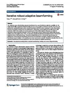
λl , ∀l ∈ L is set to 0.8 , while the power allocation coefficient is calculated according to far user’s channel gain in each cluster as used in [8] for FTPC scheme. The beamforming vector solutions of the fixed power allocation and FTPC schemes are obtained by using the proposed JBPA, in which the power allocation coefficient is no longer optimum variable. The number of cluster is set as L = 5. In this simulation, we assume that the user distances are fixed and the fast fading components of the channel vectors are averaged over 1000 simulation runs with I = 1000 randomizations. As shown in the figure, the JBPA scheme requires less transmit power than other schemes for any number of antennas to satisfy all users’ QoS requirements. The reason is that the both power allocation and beamforming which affect the users’ SINRs are considered together for JBPA scheme, which makes the intracluster interference and inter-cluster interference minimize. As expected, the consumed power decreases as the number of antennas increases due to spatially diversity gains for the three schemes. As the number of transmit antennas increases, the total transmit power differences among them decrease. This implies that beamforming plays an important role on power performance when there are a number of transmit antennas. In order to further show the performance gain of JBPA, we also give a comparison between ZFBF proposed in [6] and JBPA in Fig. 2 to investigate power consumption under different achieving throughput. The number of antennas and clusters are set as M = 5 and L = 5, respectively. We consider two different channel gain correlations scenarios: the channel gain correlation between near user and far user in each cluster is high correlation (the channel gain correlation metric is no less than 0.95) and the channel gain correlation between near user and far user in each cluster is random. Notice that an exhaustive search method is used for ZFBF approach to find the best pairs that can achieve the maximum sum rate for a given total transmit power. on one hand, the power allocation 1
Sum rate of all near users (bps/Hz)
4.5
0.35 0.3 2 clusters 3 clusters 4 clusters 5 clusters
0.25 0.2 0.15 0.1
1
2
3
4
5 6 Iteration number
7
8
9
10
Fig. 3: Convergence trajectory of Algorithm 1, M = 5, γ = 0.1.
coefficient is set as λ = 0.5 for all clusters so that the rate to near users is larger than that to far users for ZFBF. on the other hand, the power allocation coefficient is set as λ = 0.08 such that both near user and far user in a cluster achieve similar data rate. After finding the best pairs and fixing power allocation coefficient for ZFBF, we obtain the SINRs of all
2169-3536 (c) 2016 IEEE. Translations and content mining are permitted for academic research only. Personal use is also permitted, but republication/redistribution requires IEEE permission. See http://www.ieee.org/publications_standards/publications/rights/index.html for more information.
This article has been accepted for publication in a future issue of this journal, but has not been fully edited. Content may change prior to final publication. Citation information: DOI 10.1109/ACCESS.2017.2700018, IEEE Access 9 90 IUCA, ς =0.1,θ=0.1 IUCA, ς =0.3,θ=0.1 IUCA, ς =0.5,θ=0.1 IUCA, ς =0.7,θ=0.1 IUCA, ς =0.7,θ=0.05 Clustering algorithm in [3] Random user clustering Algorithm 3,ς =0.5,θ=0.1 Exhaustive search
80
Total transmit power (w)
70 60 50 40 30 20 10 0
1
2
3
4 5 6 7 The number of clusters, L
8
9
10
Fig. 4: User clustering algorithm with fixed antenna for different number of clusters for Scenario 1, M = 10, γ = 0.1.
users. For comparison fairness, the obtained SINRs are set to corresponding users of the JBPA scheme. In Fig. 2(a), when the channel gains are high correlations in each cluster, we can see that the sum rate of JBPA outperforms that of ZFBF when the total transmit power is less than 13 dB and 16 dB for λ = 0.5 and λ = 0.08, respectively. Moreover, if the channel gain correlations are random, the sum rate of JBPA significantly outperforms that of ZFBF at any transmit power for λ = 0.5 and λ = 0.08. Especially, sum rate of JBPA is three times more than that of ZFBF at 16 dB for λ = 0.08. In Fig. 2(a), we also note that the sum rate of ZFBF is superior to that of JBPA if the total transmit power is larger than 13 dB and 16 dB for λ = 0.5 and λ = 0.08, respectively. The reason is that the inter-cluster interference is completely canceled for ZFBF, such that the sum rate of all near users for ZFBF outperforms that of all near users for JBPA as the total transmit power is larger than a power threshold. This phenomenon is verified by Fig. 2(b). The complexity of ZFBF is from the inversion for an M × M matrix to obtain beamforming vectors for the given user clusters [30]. In general, ( ) the complexity of an M × M matrix inversion is O M 3 . The total L! possible user clusters are required when using exhaustive method to search the best pairs for maximizing sum rate. Therefore, the overall complexity of ZFBF is O(M 3 L!) which is exponential in L. Assume the rank of beamforming matrix is equal( to one after solving JBPA ) ( (17). The complexity of √ ) is O LM log (1/ε) O L3 M 6 + (6L + 1) L2 M 2 , where (√ ) ( ) O LM log (1/ε) and O L3 M 6 + (6L + 1) L2 M 2 denotes the total number of iteration and complexity of each iteration, respectively. The complexity of JBPA can be higher than that of ZFBF for small M and L. For larger L, the complexity in ZFBF increases exponentially, and JBPA is with polynomial-time complexity. Moreover, the beamforming vector and the power allocation can be obtained simultaneously in JBPA. In addition, to evaluate the convergence of the proposed JBPA, we consider a downlink system with M = 5 antennas under different clusters conditions. The error tolerance is
ε = 10−3 . As shown in Fig. 3, one can see that Algorithm 1 generates a non-decreasing objective of problem (17) and converges within 6 iterations for the two, three, four and five clusters. The objective (17) for two clusters is larger than that for others clusters since it consumes much less energy than others. We observe that the performance gain of the proposed user clustering algorithm is influenced by user density. In simulations, we consider two scenarios: Scenario 1, users are randomly located with uniform distribution; Scenario 2, users are densely deployed. The second scenario can be referred to as the typical scenarios in hotspot with ultra-dense user distribution. We first provide the simulation results of different user clustering algorithm for Scenario 1 in Fig. 4. This figure shows the effectiveness of proposed IUCA and Algorithm 3 for different number of clusters. The number of transmit antennas is fixed and set as M = 10. The best pairs are found by exhaustive search. Due to its high computational complexity as L increases, the optimum user clustering is considered up to L = 5, and the fast fading components of the channel vectors are averaged over 200 simulation runs with I = 1000 randomizations in this simulation. In order to investigate the impact of channel gain correlations metric ς and step size θ, ς and θ are set to different values for IUCA. As shown in the figure, the total transmit power increases as the number of clusters increases since more users are supported. We can also see that the required transmit power of the proposed IUCA approaches that of exhaustive search. We note that the transmit power of θ = 0.05 is almost same with that of θ = 0.1 for the same metric ς = 0.7. Moreover, for different number of cluster, the required total transmit power is nearly same when ς= 0.3 ∼ 0.7. Hence, the parameters ς= 0.5 and θ = 0.1 can meet the requirement of IUCA in general. In the figure, we also plot the curves of random user clustering and user clustering algorithm proposed in [3], where the strongest channel user and the weakest channel user are grouped into one cluster, the second strongest channel user and the second weakest channel user are grouped into another cluster, and so on. We can see that the required transmit power of random user clustering is larger than other schemes due to its randomness, which results in higher interference of intra-cluster and inter-cluster. Since user clustering scheme in [3] does not consider the correlation of inter-user, it consumes more energy than our proposed IUCA even if ς= 0.1. We also see that Algorithm 3 achieves the best power-saving performance. This is because that Algorithm 3 adopts various criteria in user clustering, iteration by iteration, as described in Algorithm 3. Compared with user clustering algorithm in [3], about 10% performance gain can be obtained by using IUCA and Algorithm 3. The simulation results of different user clustering algorithm for Scenario 2 are given in Fig. 5. From the figure, compared with clustering algorithm in [3], one can observe that power consumption can be reduced about 13% and 20% by using the proposed IUCA with ς=0.5, θ = 0.1 and Algorithm 3 for L = 10, respectively. The reason is that user clustering algorithm in [3] does not consider channel gain correlations, while the IUCA and Algorithm 3 do. The proposed IUCA
2169-3536 (c) 2016 IEEE. Translations and content mining are permitted for academic research only. Personal use is also permitted, but republication/redistribution requires IEEE permission. See http://www.ieee.org/publications_standards/publications/rights/index.html for more information.
This article has been accepted for publication in a future issue of this journal, but has not been fully edited. Content may change prior to final publication. Citation information: DOI 10.1109/ACCESS.2017.2700018, IEEE Access 10
VI. C ONCLUSION In this paper, we have considered iterative user clustering, and joint optimization with beamforming design and power allocation for MISO-NOMA downlink systems. All users are grouped into multiple clusters. Each cluster consists of two users and is supported by one beamforming vector. For joint power allocation and beamforming optimization, we formulated the problem subject to users’ SINR requirements. Due to its
50 Clustering algorithm in [3] IUCA, ς =0.1,θ=0.1 IUCA, ς =0.5,θ=0.1 Algorithm 3, ς =0.5,θ=0.1
45
Total transmit power (w)
40 35 30 25 20 15 10
5
6
7 8 The number of clusters, L
9
10
Fig. 5: Comparison among clustering algorithm in [3], IUCA and Algorithm 3 for different number of clusters for Scenario 2. M = 10, γ = 0.2.
45 40 35 Total transmit power (w)
with ς=0.1, θ = 0.1 obtains less power performance due to its considering less channel gain correlations. Algorithm 3 achieves the best performance since it not only considers channel gain correlations of among users, but also takes into account channel gain differences of among them. Next, we use an example, as shown in Fig. 6, to reveal the reason behind. We refer to the selection of user clustering with the largest and the third largest channel gain differences as Criterion 1 and Criterion 2. The Criterion 1 has been utilized in [6] and [9]. As shown in the figure, the powersaving performance of Criterion 1 and Criterion 2 is superior to that of clustering algorithm in [3]. Moreover, the power performance of Criterion 2 outperforms that of Criterion 1. Hence, it explains the reason why our developed solution can achieve better performance, and also verifies the necessity of considering diverse user clustering. According to the simulation results of Figs. 4∼6, we can conclude that the user clustering algorithm in [3] may achieve good performance for the cases of larger channel gain differences among users, such as Scenario 1. Note that there is the only one clustering strategy considered in [3]. No matter how the scenarios vary, all the user clusters in their work are formed by following this single criterion without optimization. As a consequence, this clustering strategy may not always lead to good performance. When the differences of channel gain are small, such as Scenario 2, the performance gains of IUCA and Algorithm 3 become impressive compared with user clustering algorithm in [3]. The reason is that diverse criteria are adopted in IUCA and Algorithm 3. Assume there are L cluster in the MISO-NOMA system. Since the strongest channel user and the weakest channel user are grouped into one cluster in user clustering algorithm proposed in [3], it requires one loop to form all clusters, and then JBPA is implemented. Its total complexity is O (L) +CJBPA , in which CJBP A is computational complexity of JBPA given in Section III-B. According( to procedure of IUCA, the total ) complexity of IUCA is O L2 + L +CJBPA . Hence, IUCA has a little higher complexity than clustering algorithm in [3]. In Algorithm 3, Bmax iterations are required to calculate the minimum transmit power and the complexity of each iteration is equal to that of( IUCA. Thus, ( ) the total ) complexity of Algorithm 3 is Bmax O L2 + L +CJBPA . Obviously, Algorithm 3 has the highest computational complexity among them. However, it can achieve best power performance as shown in Figs. 4∼6. In Algorithm 3, we proposed some simple criteria for user clustering. More sophisticated criteria may be provided in our proposed algorithmic framework to further improve system performance, which will be left to investigate in our future work.
Clustering algorithm in [3] Criterion 1, ς =0.1,θ=0.1 Criterion 1, ς =0.5,θ=0.1 Criterion 2, ς =0.5,θ=0.1
30 25 20 15 10 5 0
6
8 The number of clusters, L
10
Fig. 6: An example: comparison between different criteria and clustering algorithm in [3] in user clustering for Scenario 2. M = 10, γ = 0.2.
non-convexity, the optimization problem was further converted to an approximated convex problem by using first order Taylor series. Then, an iterative algorithm JBPA based on SDR technique was proposed to solve it. For user clustering, based on channel gain correlation and difference, a sub-optimal with low-complexity IUCA was also proposed to further reduce energy consumption. Combining with JBPA and IUCA, an algorithmic framework is developed to iteratively and jointly reduce system power consumption. Numerical results showed that the proposed iterative algorithm required less transmit power than that of power allocation and beamforming considered separately, and the performance of the proposed scheme outperformed that of ZFBF. For the considered scenarios, the proposed iterative JBPA algorithm can converge after a few iterations. Simulation results also showed that the performance of the proposed IUCA approached to that of exhaustive search and outperformed random user clustering scheme and existing user clustering approaches, which demonstrated the efficiency of the proposed IUCA. Moreover, compared to the singlecriterion user clustering, the proposed algorithmic framework has superior performance.
2169-3536 (c) 2016 IEEE. Translations and content mining are permitted for academic research only. Personal use is also permitted, but republication/redistribution requires IEEE permission. See http://www.ieee.org/publications_standards/publications/rights/index.html for more information.
This article has been accepted for publication in a future issue of this journal, but has not been fully edited. Content may change prior to final publication. Citation information: DOI 10.1109/ACCESS.2017.2700018, IEEE Access 11
VII. ACKNOWLEDGEMENTS The work of Z. Liu, N. Zhang and G. Kang was supported by the National Natural Science Foundation of China under Grant 61501056 and National Science and Technology Major Project of China under Grant 2016ZX03001012. The work of L. Lei and S. Chatzinotas was supported by the Luxembourg National Research Fund (FNR) Multi-Annual Thematic Research Programme (CORE) projects SEMIGOD and SATSENT. R EFERENCES [1] Y. Saito, Y. Kishiyama, A. Benjebbour, T. Nakamura, A. Li, and K. Higuchi, “Non-orthogonal multiple access (NOMA) for cellular future radio access,” in Proc. IEEE Veh. Technol. Conf., Jun. 2013, pp. 1-5. [2] Z. Ding, Y. Liu, J. Choi, Q. Sun, M. Elkashlan, C. I, and H. V. Poor, “Application of non-orthogonal multiple access in LTE and 5G networks,” IEEE Commu. Mag., vol. 55, no. 2, pp. 185-191, Feb. 2017. [3] M.S. Ali, H. Tabassum, and E. Hossain, “Dynamic user clustering and power allocation in Non-orthogonal multiple access (NOMA) systems,” IEEE Access., vol. 4, no. 8, pp. 6325-6343, Aug. 2016. [4] P. Xu, Z. Ding, X. Dai, and H. V. Poor, “A new evaluation criterion for non-orthogonal multiple access in 5G software defined networks,” IEEE Access., vol. 3, no. 9, pp. 1633-1639, Sep. 2015. [5] K. Higuchi and Y. Kishiyama, “Non-orthogonal multiple access using intra-beam superposition coding and successive interference cancellation for cellular MIMO downlink,” IEICE Trans. Commun., vol. E98-B, no. 9, pp. 1888-1895, Sep. 2015. [6] B. Kim, S. Lim, H. Kim, S. Suh, J. Kwun, S. Choi, C. Lee, S. Lee, and D. Hong, “Non-orthogonal multiple access in a downlink multiuser beamforming system,” in Proc. IEEE Military Commun. Conf., Nov. 2013, pp. 1278-1283. [7] S. Liu, C. Zhang, and G. Lyu, “User selection and power schedule for downlink non-orthogonal multiple access (NOMA) system,” in IEEE Int. Conf. Commun. Workshop, Jun. 2015, pp. 2561-2565. [8] J. Kim, J. Koh, J. Kang, K. Lee and J. Kang, “Design of user clustering and precoding for downlink non-orthogonal multiple access (NOMA),” in Proc. IEEE Military Commun. Conf., Oct. 2015, pp. 1170-1175. [9] M.S. Ali, E Hossain, and D Kim, “Non-Orthogonal Multiple Access (NOMA) for Downlink Multiuser MIMO Systems: User Clustering, Beamforming, and Power Allocation”. IEEE Access., vol. 5, pp. 565577, 2017. [10] Q. Zhang, Q. Li, and J. Qin, “Robust beamforming for non-Orthogonal multiple access systems in MISO channels”. IEEE Trans. Veh Technol., vol. 65, no. 12, pp. 10231-10236, Dec. 2016. [11] Z. Ding, R. Schober, and H. V. Poor, “A general MIMO framework for NOMA downlink and uplink transmission based on signal alignment,” IEEE Trans. Wireless Commun., vol. 15, no. 6, pp. 4438-4454, Jun. 2016. [12] M. Hanif, Z. Ding, T. Ratnarajah and G. K. Karagiannidis, “A minorization-maximization method for optimizing sum rate in the downlink of non-orthogonal multiple access systems,” IEEE Trans. Signal Process., vol. 64, no. 1, pp. 76-88, Jan. 2016. [13] J. Choi,“Minimum power multicast beamforming with superposition coding for multiresolution broadcast and application to NOMA systems,” IEEE Trans. commun., vol. 63, no. 3, pp. 791-800, Mar. 2015. [14] Z. Chen, Z. Ding, and X. Dai, “Beamforming for combating inter-cluster and intra-cluster interference in hybrid NOMA systems,” IEEE Access., vol. 4, no. 8, pp. 4452-4463, Aug. 2016. [15] Y. Li, M. Jiang, Q.Zhang, Q. Li and J. Qin. “Secure beamforming in downlink MISO non-orthogonal multiple access Systems,” To appear in IEEE Trans. Veh Technol., 2017. [16] S. Sanayei and A. Nosratinia, “Antenna selection in MIMO systems,” IEEE Commun. Mag., vol. 42, no. 10, pp. 68-73, Oct. 2004. [17] L. Lei, D. Yuan, and P. Värbrand, “On power minimization for nonorthogonal multiple access (NOMA),”. IEEE Commun. Letts., vol. 20, no. 12, pp. 2458-2461, Dec. 2016. [18] A. Beck, A. Ben-Tal, and L. Tetruashvili, “A sequential parametric convex approximation method with applications to nonconvex truss topology design problems,” J. Global Optim., vol. 47, no. 1, pp. 2951, Jan. 2010. [19] Z. Luo, W. Ma, A. So, Y. Ye, and S. Zhang, “Semidefinite relaxation of quadratic optimization problems,” IEEE Signal Process. Mag., vol. 27, no. 3, pp. 20-34, May. 2010.
[20] Ö. T. Demir and T.E. Tuncer, “Antenna selection and hybrid beamforming for simultaneous wireless information and power transfer in multigroup multicasting systems,” IEEE Trans. Wireless Commun., vol. 15, no. 10, pp. 6948-6962, Oct. 2016. [21] M. Grant and S. Boyd, “CVX: Matlab software for disciplined convex programming, version 2.1,” http://cvxr.com/cvx/, Jun. 2015. [22] B. Marks and G. Wright,“A general inner approximation algorithm for nonconvex mathematical programs,” Oper. Res., vol. 26, no. 4, pp. 681683, Jul./Aug. 1978. [23] E. Karipidis, N.D Sidiropoulos, and Z. Luo, “Quality of service and maxmin fair transmit beamforming to multiple cochannel multicast groups,” IEEE Trans. Signal Process., vol. 56, no. 3, pp. 1268-1279, Mar. 2008. [24] K. T. Phan, S. A. Vorobyov, N. D. Sidiropoulos, and C. Tellambura,“Spectrum sharing in wireless networks via QoS-aware secondary multicast beamforming,” IEEE Trans. Signal Process., vol. 57, no. 6, pp. 2323-2335, Jun. 2009. [25] Z. Ding, P. Fan, and H. V. Poor, “Impact of user pairing on 5G nonorthogonal multiple access downlink transmissions,” IEEE Trans. Veh Technol., vol. 65, no. 8, pp. 6010-6023, Aug. 2016. [26] L. Lei, D. Yuan, C. K. Ho, and S. Sun, “Optimal cell clustering and activation for energy saving in load-coupled wireless networks,” in IEEE Trans. Wireless Commun., vol. 14, no. 11, pp. 6150–6163, Nov. 2015. [27] Z. Liu, G. Kang, L. Lei, N. Zhang and S. Zhang, “Power Allocation for Energy Efficiency Maximization in Downlink CoMP Systems With NOMA", IEEE Wireless Communications and Networking Conference (WCNC), Mar. 2017. [28] Z. Ding, Z. Yang, P. Fan and H. V. Poor. “On the performance of non-orthogonal multiple access in 5G systems with randomly deployed users,”. IEEE Sig Proc Lett., vol. 21, no. 12, pp. 1501-1505, Dec. 2014. [29] D. Tse and P. Viswanath, Fundamentals of Wireless Communication. Cambridge U.K.: Cambridge Univ. Press, 2005. [30] T. Yoo and A. Goldsmith, “On the optimality of multiantenna broadcast scheduling using zero-forcing beamforming,”. IEEE J.Sel.Areas Commun., vol. 24, no. 3, pp. 528-541, Mar. 2006.
2169-3536 (c) 2016 IEEE. Translations and content mining are permitted for academic research only. Personal use is also permitted, but republication/redistribution requires IEEE permission. See http://www.ieee.org/publications_standards/publications/rights/index.html for more information.