This work was supported by the Office of Naval Research under grant ...... [10] C.
Lacatus and D. C. Popescu, “Interference avoidance with incremental.
Joint Power Control and Waveform Adaptation for Distributed Networks R. Menon, A. B. MacKenzie, R. M. Buehrer and J. H. Reed The Bradley Department of Electrical and Computer Engineering Virginia Tech, Blacksburg, VA {rmenon, mackenab, buehrer, reedjh}@vt.edu Abstract— This paper presents a joint power control and waveform adaptation algorithm for networks with non-colocated receivers, amenable to a distributed implementation. The proposed algorithm allows users to meet their target Signal to Interference plus Noise Ratio (SINR) requirements while reducing the transmit power-levels in the network. The performance of the algorithm is investigated via theoretical-analysis and simulations. It is shown that the joint algorithm results in better solutions than a pure power-control or a pure waveform adaptation algorithm.
I. I NTRODUCTION Recent research and industry trends suggest a shift towards dynamic and distributed spectrum access. Distributed usernodes with distributed receivers are required to independently adapt their transmission parameters in a way that facilitates multi-user communication while at the same time conserving network resources. This paper proposes a joint power-control (PC) and waveform-adaptation (WA) algorithm framework which allows users to achieve a target performance while reducing the transmit power-levels in a distributed network. Distributed WA techniques, which involve the design of signature sequences or waveforms by users such that multiuser interference is reduced, have been extensively investigated for networks with a centralized receiver (or equivalently networks with co-located receivers) ([1], [2], [3] and references within). The symmetry of interference between users in these networks, lead to very simple greedy adaptation WA schemes. However, these same techniques lead to non-convergence in networks with non-colocated receivers since the mutual interference between users is asymmetric [4]. Hence convergent WA techniques in these networks require some feedback in the network and some possible schemes are proposed in [5]. One of the seminal investigations of the design of PC algorithms for achieving target-SINRs was presented by Yates in [6]. The proposed algorithms were based on the“standard interference function update” and convergence was shown under a variety of network scenarios. Extensions of the above framework with power limitations and a pricing constraint on the battery life were developed in [7]. PC algorithms based on a potential game framework have been proposed in [8]. Since both transmit power-levels and transmit waveforms influence the interference in the network, it is believed that This work was supported by the Office of Naval Research under grant N000140310629, NSF under Grant No. 0448131 and ETRI, Korea.
joint PC and WA can lead to more efficient network solutions. However, such algorithms have been previously analyzed only for networks with centralized or colocated receivers ([9], [10], [11] and references within) and, as is the case with pure WA, direct extensions of these algorithms to networks with distributed receivers do not lead to convergence [11]. In this paper, we propose a joint algorithm that converges in distributed networks and which allows users to achieve target SINRS while reducing the sum of power-levels in the network. The rest of the paper is organized as follows: The system model is described in Section II. Section III provides the background and motivation for the joint algorithm. The proposed algorithm is discussed in Section IV. An extension of the proposed algorithm with two stages that leads to lower transmit power-levels in the network is described in Section V. Finally, Section VI concludes the paper. II. S YSTEM M ODEL We consider a distributed network, made up of a cluster of transmit and receive node-pairs (as in an ad hoc network). Figure 1 shows an example network with transmit-receive node-pairs indicated by arrows. This network model is a generalization of a network with co-located or centralized receivers and hence the results presented here are applicable to the centralized network scenario as well. Receiver Node
Transmitter Node
Fig. 1.
Example network with multiple un-coordinated receivers
A signal-space characterization is used to represent transmit waveforms [2] for nodes. This signal-space representation specifies the transmit waveform of a node in orthogonal signal dimensions (time or frequency) and is referred to as the signature sequence of the node. Let N denote the number of transmission dimensions available to the network and K denote the number of transmitting nodes in the network. Vector sk ∈ RN ×1 is used to denote the signature sequence associated with transmitting node k. The signature sequences are allowed
694 1930-529X/07/$25.00 © 2007 IEEE This full text paper was peer reviewed at the direction of IEEE Communications Society subject matter experts for publication in the IEEE GLOBECOM 2007 proceedings.
to have real values (as opposed to bi-polar sequences). Without loss of generality, the signature sequences are assumed to have unit norm and � N − 1 dimensional � hence constrained to the 2 sphere S = sk ∈ RN ×1 : �sk � = 1 . The set of allowable transmit power-levels are denoted by P and the transmit power level of the k th node is denoted by pk ∈ P . P is assumed to be a compact set with pmax = max{P } and pmin = min{P }. The fading coefficient of the channel between the k th transmit node and the j th receive node is denoted by gkj . The channel is assumed to be constant over all signal dimensions and also constant over the time required for the adaptation process. The data symbol (assumed to be of zero-mean and unit-variance) transmitted from the k th transmit node is denoted by bk . The received signal at the j th receive node is then given by �√ pk gkj sk bk + z, (1) rj = k∈K
where K = [1, . . . , K], rj ∈ RN ×1 , and the vector z ∈ RN ×1 models zero mean additive Gaussian noise with variance σ 2 . In the analysis in this paper, the signature sequences from multiple users are assumed to be synchronized at the receivers. However, this is done only for the sake of notational simplicity. Similar to the analysis in [12] (which considers WA in centralized networks), the scheme can be easily extended to an asynchronous system. Interference is caused at a receive node by transmissions from nodes different from the one associated with the particular receive node. Interference caused is influenced by the correlation between the waveforms of user nodes, transmit power levels and the channel characteristics. III. F ORMULATION OF TARGET-SINR P ROBLEM Our goal in this paper is to design an adaptation framework where users in the network are able to achieve a feasible target SINR while at the same time minimizing the required transmit power levels in the network. The SINR of the k th user in the network is given by 2 pk gkk . γk = Ik (p, s)
(2)
Here, Ik (p, s) is the interference-plus-noise at the k th user’s receive-node and Ik (p, s) = sTk Rk sk + σ 2 , � is given by T 2 s s p where Rk = j∈K,j�=k j j j gjk . A target SINR vector T γ¯ = [γ¯1 , . . . , γ¯K ] is feasible if there exists a vector p = T T [p1 , . . . , pK ] ∈ P K and a sequence set s = [s1 , . . . , sK ] ∈ K S such that γk ≥ γ¯k , ∀k ∈ K. The adaptation objective can be formulated as the following optimization problem: � pk min p,s k∈K (3) P1 : 2 subject to: pk gkk ≥ γ¯ , st s = 1 ∀k k k k Ik (p,s) Now, consider the following optimization problem: � Ik (p,s)γ¯k min 2 gkk p,s k∈K P2 : subject to: pk ≥ γ¯k Ik (p,s) , stk sk = 1 ∀k g2 kk
(4)
It can be seen that problems P 1 and P 2 are closely related and γ¯k ∀k can be are equivalent if the condition pk = γ¯k Ik (p,s) 2 gkk satisfied for the target power-levels and signature sequences at the optimal point. The combined power and WA framework we develop is a sub-optimal iterative approach to solving problem P 2 and hence problem P 1. The framework consists of a WA component that iteratively reduces the objective function of P 2 and a PC component that ensures that the transmit power levels ∀k, are feasible (i.e. the power constraints, pk ≥ γ¯k Ikg(p,s) 2 kk for P 1 and P 2 are satisfied). Let us first consider the design of the WA component. The objective function of P 2 can be written as follows: � γ¯k sH Rk sk k . (5) Isum (s) = 2 gkk k∈K
The terms involving the k � γ¯k sH k Isum (s) = �
+
j∈K,j�=k
�
+
th
�
user can be separated to yield
j∈K,j�=k
2 2 sj sH j pj gjk + σ I
sk
2 gkk
H 2 γ¯j sH j sk sk sj pk gkj 2 gjj � � H H 2 2 γ¯j sj sl sl pl glj + σ I sj
j∈K,j�=k
l∈K,l�=k,j
�
2 gjj
(6)
.
Non-contributing terms
The effects of the actions of the kth user are only perceived in the first two terms: the first term is the inverse-SINR of the user at its receive node and the second term is the interference caused by the user to all other users in the network. Therefore, the user can iteratively decrease Isum (s) if it adapts its waveform to decrease function uk (s) = sTk Xk sk , where Xk =
� γ¯k Rk + 2 gkk
j∈Kj�=k
2 γ¯j sj sTj pk gkj . 2 gjj
(7)
A user’s adaptation thus incorporates the effect of the user’s waveform on other users in the network. It can be observed that matrix Xk is a symmetric matrix since it consists of terms that are weighted cross-correlations of the transmit sequences of users and which are hence symmetric. Hence the utility function is the negative of a weighted Rayleigh quotient of Xk (refer [13] for a definition of Rayleigh quotient). This is maximized by the eigenvector corresponding to the minimum eigenvalue of Xk [13]. Therefore a possible way for a user-k to adapt its waveform such that it reduces uk (s) is to replace sk by the minimum eigenvector of Xk (denoted by sk,EV I ). This waveform iteration is referred to as the eigen-value-iteration (EVI). A similar waveform iteration is discussed in [5]. Note that to implement the EVI, each adapting node requires access to the signature sequences of all transmit-nodes in the network and the received power levels at all receivenodes from each transmit-node. This can be accomplished by
695 1930-529X/07/$25.00 © 2007 IEEE This full text paper was peer reviewed at the direction of IEEE Communications Society subject matter experts for publication in the IEEE GLOBECOM 2007 proceedings.
requiring each transmit node to broadcast its sequence and transmit power level and each receive-node to broadcast the channel coefficients at the beginning of the adaptation process and requiring the adapting node to broadcast its new signature sequence after each adaptation. However, this process could considerably increase network overhead. This motivates the gradient-based-iteration (GI), an extension of the WA scheme proposed in [14] and described in detail in Appendix I, which involves limited feedback in the network. In this approach a user adapts to a waveform that improves its SINR (using a gradient-scheme which only utilizes local information available at the receiver) and sticks to the adaptation if the sumchange in weighted inverse SINR at all the other receivers (a measure of interference) in the network is negative. Hence feedback in the network comprises only of receivers that can hear the adapting user sending their change in weighted inverse SINR due to the adaptation. The sequence that user-k adapts to while following GI is denoted by sk,GI . It can be shown that this adaptation reduces function uk [14]. IV. A LGORITHM FOR J OINT P OWER C ONTROL AND WAVEFORM A DAPTATION A. Algorithm Description As mentioned earlier, the iterative algorithm (stated below) has two components: the WA component which reduces the correlation between user transmissions and the PC component which ensures that the target SINRs of users are met. Target-based Power and Waveform Adaptation Algorithm 1) Initialize transmit power of all users to pk = pini,k = γ¯k σ 2 . 2 gkk 2) Assign random transmit sequences to all users. 3) For k ∈ K a) Replace sk with s�k . γ¯k sT k Rk sk b) If pk < , replace pk by p�k = 2 gkk � � T γ¯k sk Rk sk , pmax . min g2 kk
4) Repeat step 3 until a termination criterion is reached. Here, s�k = sk,EV I (defined in Section III) if EVI is used and s�k = sk,GI (defined in Appendix I) if GI is used. Note that the PC component of the algorithm (Step 3.b) is based only on SINR measurements at a user’s receiver. Hence most of the network overhead required to implement the algorithm is due to the WA component (Step 3.a). This overhead can be substantially reduced by using GI instead of EVI. B. Convergence and Fixed Points Consider the following function: V (p, s) =
Isum (p, s) + C � , pk
(8)
k∈K
� where C is a constant with C > Kpmax
� �
i∈K j∈K
2 γ¯j gij 2 gjj
2 .
The following two theorems show that at each iteration, the
waveform and power adaptation by a user monotonically decreases the above function. Theorem 1: Each WA, where user-k (k ∈ K) replaces sequence sk by s�k decreases function V (p, s). Proof: The change in function V (p, s) when user-k (k ∈ K) replaces sk by s�k is given by � � t s Xk sk − s�k t Xk s�k � . (9) V (p, s) − V (p, (s�k , s−k )) = k pk k∈K
t
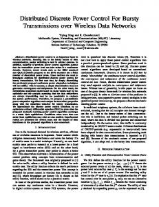
Since EVI or GI is used, s�k Xk s�k < stk Xk sk . Therefore, V (p, s) − V (p, (s�k , s−k )) > 0. Theorem 2: Each power adaptation, where user-k (k ∈ K) replaces power-level pk by p�k decreases function V . Proof: Given in Appendix II. The target-based power and WA algorithm thus iteratively decreases the value of function V (p, s), where s ∈ S K and p ∈ P K . Also S K and P K are both compact sets and the value of V is bounded from below. Since a monotonic sequence converges if it is bounded [15], the algorithm that generates the sequence also converges. A more precise proof can also be easily formulated using Zangwill’s convergence theorem-A [16]. However, it is not included here for the sake of brevity. C. Simulation-based Performance Analysis A distributed network is simulated by placing K transmit and receive nodes uniformly in a circular region with radius R (R = 5m in the simulations). The power at a receive node from a transmit-node at a distance of r from the transmit node is assumed to be given by rpαk , where pk is assumed to be the power received from a transmit node at a distance of 1m and α is the path-loss exponent (α = 3 in the simulations). The path loss at a distance of 1m is assumed to be 40dB and pmax = 500mwatts. Noise power is assumed to be −90dBw per signal dimension. Figure 2 illustrates the SINRs of the users that over multiple iterations of the joint algorithm. It is seen that the proposed algorithm (with both EVI and GI) converges and users are able to achieve SINRs that are greater than the required target SINRs. Note that users over-achieve the required SINRs since the algorithm does not allow transmit power-levels to be reduced. It can also be seen that using GI as opposed to EVI increases the number of iterations required for convergence. This is due to the fact that EVI corresponds to the optimal WA at each iteration. Figure 3 shows the value of function V (p, s) for multiple iterations of the algorithm. It can be observed, as expected, that the algorithm iteratively decreases this function. The performance of the proposed joint algorithm is now compared with a pure WA algorithm (which is essentially the proposed algorithm without the power update step 3.b and an extension of the pure WA algorithms in [5]) and the pure PC algorithm proposed in [6]. Two cases of the pure PC algorithm are considered: in the first case, users transmit using random sequences and in the second case, users choose a signal-dimension randomly from the N available signal dimensions. Figure 4 plots histograms of the number of users
696 1930-529X/07/$25.00 © 2007 IEEE This full text paper was peer reviewed at the direction of IEEE Communications Society subject matter experts for publication in the IEEE GLOBECOM 2007 proceedings.
5
receiver. Hence the joint algorithm further (and substantially) improves the network solution that results from a pure WA algorithm with minimal additional feedback.
1 1 2
4
3 3
SINR (dB)
2 3 6 2
1−stage Joint Algorithm with EVI 1−stage Joint Algorithm with GI Pure PC algorithm with random spreading sequences Pure PC algorithm with random choice of dimensions Pure WA with EVI [5]
60
7 4 5 7 4
1
50
6 Percentage number of runs
5
0
Solid − EVI Dotted − GI −1
−2
2
4
6 8 10 Number of Round−robin Iterations
12
14
40
30
20
Fig. 2. Convergence of user-SINRs in a network with 7 users sharing 5 signal dimensions and target SINRs, γ ¯ = [5111111]dB. Single-stage Algorithm is employed. The number of bits fedback for GI is 1(q = 1).
10
0
0
1
2
3
4
5
6
7
Number of users that achieve target−SINRs 85.5
Fig. 4. Normalized histogram of the number of users that achieve their Target-SINRs that result from different algorithms, over 500 realizations of a random network and with random initial signature sequences. Networks have 7 users sharing 5 signal dimensions. Target SINRs, γ ¯ = [5111111]dB.
85
84.5
Value of V(s,p)
84
83.5
1.1
Solid − EVI Dotted − GI
83
1 0.9
82.5
0.8 82
5
10
15
20
25
30
35
40
Number of iterations (Not round−robin)
Fig. 3. Plot to illustrate that function V (s, p) monotonically decreases. Network has 7 users sharing 5 signal dimensions and target SINRs, γ ¯ = [5111111]dB. Single-stage Algorithm is employed. The number of bits fedback for GI is 1(q = 1).
Cumulative distribution
0.7 81.5
0.6 0.5
2−stage Joint Algorithm with EVI 2−stage Joint Algorithm with GI 1−stage Joint Algorithm with EVI 1−stage Joint Algorithm with GI Pure PC algorithm with random spreading sequences Pure PC algorithm with random choice of dimensions
0.4 0.3 0.2 0.1
0
0.5
1
1.5
2
2.5
3
3.5
4
4.5
5
Final transmit power−levels (×100 mwatts)
that achieve target-SINRs resulting from different algorithms. In the simulations, to ensure a fair comparison, the transmit power-level for all users in the pure WA algorithm, is fixed to be the average transmit-power level resulting from the joint algorithm. It is found that the proposed joint algorithm leads to a larger number of users achieving their target SINRs than both the pure PC and the pure WA algorithm. In addition, as can be observed from Figure 5, which plots the cumulative distribution of the transmit power-levels resulting from different algorithms, the proposed (1-stage) algorithm leads to lower transmit power-levels than the pure PC algorithms. It can also be observed from Figure 4 that in algorithms which incorporate WA, users are able to achieve their target SINRs in a larger percentage of network scenarios, as compared to in pure PC algorithms. This is due to the fact that WA reduces the correlation between sequences and hence the effective interference at receivers. Therefore the RHS of ∀k in problem P 2 is reduced, the constraint pk ≥ γ¯k Ikg(p,s) 2 kk leading to a larger set of feasible power-vectors. Also, note that a majority of the overhead in the network for the joint algorithm results from the WA component. The PC component for a user is based only SINR measurement at the user’s
Fig. 5. Cumulative distribution of the transmit power-levels of users that result from different algorithms, over 500 realizations of a random network and with random initial signature sequences. Networks have 7 users sharing 5 signal dimensions. Target SINRs, γ ¯ = [5111111]dB.
V. T WO - STAGE A LGORITHM FOR J OINT P OWER C ONTROL AND WA A LGORITHM Note that, in the proposed algorithm, users might overachieve their target-SINRs. This can be remedied by including a second stage, where when starting from feasible target SINRs, user power-levels are decreased such that the achieved SINRs are equivalent or nearer to the target requirements. A. Algorithm Description Two-stage Target-based Power and Waveform Adaptation Algorithm 1) Initialize transmit power of all users to pk = pini,k . 2) Assign random transmit sequences to all users 3) For k ∈ K a) Replace sk with s�k . γ¯ sT R s b) If pk < k gk2 k k , replace pk by p�k . kk
697 1930-529X/07/$25.00 © 2007 IEEE This full text paper was peer reviewed at the direction of IEEE Communications Society subject matter experts for publication in the IEEE GLOBECOM 2007 proceedings.
γ¯ sT R s
k k k k , Let pk a) If pk > 2 gkk � � T γ¯k sk Rk sk , pmin . max g2
=
pˇk
=
kk
6) Repeat step 5 until a termination criterion is reached. B. Convergence and Fixed Points The first phase of the algorithm is the same as that proposed in the previous section. Hence the first phase converges by the same arguments. The convergence of the second-stage of the algorithm can be established using the following theorem. Theorem 3: Each power adaptation in the second stage of the algorithm, where user-k (k ∈ K) replaces transmit power level pk by pˇk ∈ P does not increase function Isum (in other words the objective function of P 2). Proof: The change in function Isum when the k th user adapts from power-level pk to power-level pˇk is given by γ¯k sH γ¯k sH k Rk sk k Rk sk − 2 2 gkk gkk 2 H H � pˇk gkj sj sk sk sj 2 pj gjj
Isum (s, p) − Isum (s, (p−k , pˇk )) = +
� j∈K,j�=k
2 H pk gkj sj sk sH k sj − 2 pj gjj
j∈K,j�=k
(10) The first two terms are independent of the transmit power-level of the k th user. Since pˇk ≤ pk , the sum of the last two terms is positive and hence the power-adaptations in the second-stage do not increase Isum . This is also intuitive since a reduction in the transmit power-level of a user decreases the interference it causes to all the other users in the network. From the above theorem it can be seen that the second stage of the joint algorithm monotonically decreases function Isum which is bounded from below. Since a monotonic and bounded function converges, the second stage of the algorithm also converges. The corollary below shows that when starting from a feasible solution, the second-stage of the algorithm maintains the feasibility constraint for all users. Corollary 1: When starting from feasible power-levels, each power adaptation in the second stage of the algorithm maintains the feasibility condition of the power levels of all , ∀k. users i.e. pk ≥ γ¯k Ikg(p,s) 2 kk Proof: It follows from the proof of Theorem 3, that ∀k. a power-adaptation does not decrease function γ¯k gIk (p,s) kk2 Thus when starting from a feasible solution, the condition is maintained ∀k. pk ≥ γ¯k Ikg(p,s) 2 kk The following theorem characterizes the solution of the twostage algorithm for a specific network scenario. Theorem 4: In an under-loaded (K < N ) or equally-loaded (K = N ) network scenario with a white noise process, the joint two-stage algorithm with EVI as the WA component converges to the optimal solution. Proof: The optimal solution in an under-loaded or equally-loaded network corresponds to an allocation of orthogonal sequences to users and transmit power-levels given
by pk = pini,k , ∀k (provided these power-levels are within the transmission constraints.). Let (s∗ , p∗ ) be the fixed point of the joint power and WA algorithm. Let Aw (p) be the WA component of the algorithm when the power-levels are fixed at p and let Ap (s) be the PC component when the waveforms are fixed at s. Then it can easily be shown that s∗ is a fixed point of Aw (p) and p∗ is a fixed point of Ap (s). It is shown in [14] that orthogonal sequences are the fixed points of EVI. Hence s∗ corresponds to a set of orthogonal sequences. Since orthogonal sequences are allocated to different users, the interference between users is zero and the first-stage of the joint algorithm results in transmit-power levels that satisfy pk ≥ pini,k , ∀K (provided these power-levels are within the transmission constraints.). The second stage of the algorithm then reduces the transmit power-levels of algorithms that over-achieve the required target SINRs resulting in pk = pini,k , ∀k. C. Simulation-based Performance Analysis The SINRs of users over multiple iterations of the joint two-stage algorithm is illustrated in Figure 6. The simulated network has the same parameters as that in the previous section. The two stages of the algorithm can be clearly identified in the figure. In the second stage of the algorithm, power-levels of users (with feasible transmit power-levels) are reduced such that target-SINRs are just met. It can also be observed from Figure 5 that, as expected, the two-stage algorithm results in lower transmit power-levels than the single-stage algorithm. However, the two-stage algorithm requires some additional iterations as compared to the single-stage algorithm. 12 10 8 6 1 SINR(dB)
4) Repeat step 3 until a termination criterion is reached. Stage-2 5) For k ∈ K
4 2 2−7
0
Solid − EVI Dotted − GI
−2 −4 −6 5
10 15 Number of Round−robin Iterations
20
Fig. 6. Convergence of user-SINRs in a network with 7 users sharing 5 signal dimensions and target SINRs, γ ¯ = [5111111]dB. Two-stage Algorithm is employed. The number of bits fedback for GI is 1(q = 1).
VI. S UMMARY Single-stage and two-stage joint power-control and waveform adaptation algorithms that converge in networks with non-colocated receivers and which are amenable to a distributed implementation, were developed in this paper. Previously, convergent joint power and WA algorithms have been developed only for networks with centralized or co-located receivers. The proposed algorithms allow users to achieve their
698 1930-529X/07/$25.00 © 2007 IEEE This full text paper was peer reviewed at the direction of IEEE Communications Society subject matter experts for publication in the IEEE GLOBECOM 2007 proceedings.
target-SINRs while reducing the transmit power-levels in the network. The convergence and performance of both algorithms were investigated via theoretical-analysis and simulations. It was shown that the joint algorithms result in better solutions than a pure PC or a pure WA algorithm. In addition, in underloaded and equally-loaded scenarios, the two-stage algorithm with eigen-value iterations converges to the optimum allocation. Note that the joint algorithm requires additional network overhead as compared to a pure PC algorithm. However, as was shown in the paper, the use of gradient iterations can considerably reduce this overhead. A PPENDIX I
(11)
Note that the signature sequence sk and Rk are usually known at the receiver corresponding to user k and consequently, dk (sk , s−k ), can be estimated no additional overhead in the network. The k th receive-node then finds q (q ∈ {1, . . . , N }) dimensions in which vector dk (sk , s−k ) has the largest magnitude(referred to here as the ascent direction and denoted by aq ). The variable q is used to control the amount of feedback in the network. The transmit-sequence of the user is then adapted along this direction if interference in the network is decreased. The GI algorithm component for user-k can be written as follows: 1) Calculate dk (sk , s−k ) and aq at receive-node k. 2) Feedback aq to the transmit-node k. = 3) Adapt transmit-node k to sequence s˜k sk +�k aq √ , where � is the adaptation k (sk +�k aq )H (sk +�k aq ) constant. 4) All receivers in the network send change in weighted γ I inverse SINR ( gj2 j ). jj 5) If the sum change in weighted inverse SINR is negative (interference in the network is reduced), set sk,GI = s˜k . Else set sk,GI = sk . It can easily be shown that the above adaptation reduces the value of function uk [14]. A PPENDIX II The change in the value of function V (.) due to the power adaptation by user k is given by �
V (p, s) − V ((p�k , p−k ) , s) = � −
sT k Rk sk γ¯k 2 gkk
� + p�k B + C
B=
� j�=k
K �
j=1
�
� + pk B + C
�
pk + D
(12)
.
p�k + D
�=C+ � Here, C
sT k Rk sk γ¯k 2 gkk
γ¯j
j�=k T 2 sT k sj sj sk gkj γ¯j . 2 gjj
� i�=j,k
T 2 sT j si si sj gij 2 gjj
Let p¯k =
, D =
sT k Rk sk γ¯k . 2 gkk
� j�=k
V (p, s) − V ((p�k , p−k ) , s) � � � � 1 1 � − � p¯k + pk B + C p¯k + p¯k B + C = pk + D p�k + D � � p¯k pk B + C p¯k B + C p¯k − + − = pk + D p�k + D pk + D p�k + D (13) � � pk B + C p�k B + C p¯k − p¯k + − (Since p�k > pk ) > p�k + D pk + D p�k + D � (p�k − pk ) pk B (p�k − p¯k ) + BD (pk − p�k ) + C = (pk + D) (p�k + D)
�
If C is chosen such that C > Kpmax
The gradient of Ik (s) with respect to sequence sk is � � � � 2 sTk sk Rk sk − 2 sTk Rk sk sk duk (s) dk (s) = = . 2 dsk (sTk sk )
Substituting,
pj and
� �
i∈K j∈K
2 γ¯j gij 2 gjj
2
(Note
that such a choice is possible since the all values are bounded and can easily be estimated for a given system), V (p, s) − V ((p�k , p−k ) , s) > 0.
(14)
R EFERENCES [1] S. Ulukus and R. Yates, “Iterative construction of optimum signature sequence sets in synchronous CDMA systems,” IEEE Trans. Inform. Theory, vol. 47, pp. 1989–1998, July 2001. [2] C. Rose, S. Ulukus, and R. D. Yates, “Wireless systems and interference avoidance,” IEEE Trans. Wireless Commun., vol. 1, pp. 415–427, July 2002. [3] J. Hicks, A. B. MacKenzie, J. Neel, and J. Reed, “A game theory perspective on interference avoidance,” in IEEE Global Telecom. Conf., vol. 1, pp. 251–261, Nov./ Dec. 2004. [4] C. W. Sung and K. K. Leung, “On the stability of distributed sequence adaptation for cellular asynchronous DS-CDMA systems,” IEEE Trans. Inform. Theory, vol. 49, pp. 1828–1831, July 2003. [5] R. Menon, A. B. MacKenzie, R. M. Buehrer, and J. H. Reed, “A gametheoretic framework for interference avoidance in ad-hoc networks,” in IEEE Global Telecom. Conf., Nov. 2006. [6] R. Yates, “A framework for uplink power control in cellular radio systems,” IEEE J. Select. Areas Commun., vol. 13, pp. 1341–1347, Sept. 1995. [7] C. U. Saraydar, N. B. Mandayam, and D. J. Goodman, “Efficient power control via pricing in wireless data networks,” IEEE Trans. Commun., vol. 50, pp. 291–303, Feb. 2002. [8] J. O. Neel, Analysis and Design of Cognitive Radio Networks and Distributed Radio Resource Management Algorithms. PhD thesis, Virginia Polytechnic and State University, Dec. 2006. [9] D. C. Popescu and C. Rose, “Interference avoidance and power control for uplink CDMA systems,” in The 58th IEEE Veh. Technol. Conf., vol. 3, pp. 1473–1477, Oct. 2003. [10] C. Lacatus and D. C. Popescu, “Interference avoidance with incremental power updates for uplink CDMA systems,” in IEEE WCNC, vol. 4, pp. 1842–1847, Apr. 2006. [11] C. W. Sung, K. W. Shum, and K. K. Leung, “Stability of distributed power and signature sequence control for CDMA systems-a gametheoretic framework,” IEEE Trans. Inform. Theory, vol. 52, pp. 1775– 1780, Apr. 2006. [12] S. Ulukus and R. D. Yates, “Signature sequence optimization in asynchronous CDMA systems,” in IEEE Int. Conf. Commun., vol. 2, pp. 545– 549, June 2001. [13] G. H. Golub and C. F. V. Loan, Matrix Computations. Johns Hopkins University Press, Nov. 1996. 3rd edition. [14] R. Menon, A. B. MacKenzie, R. M. Buehrer, and J. H. Reed, “Interference avoidance in networks with distributed receivers.” Submitted to IEEE Trans. Commun., [Online], https://filebox.vt.edu/˜rmenon/Distributed/AdHoc Tcom.pdf. [15] W. Rudin, Principles of Mathematical Analysis. McGraw-Hill, 1976. 3rd edition. [16] W. I. Zangwill, Nonlinear programming; a unified approach. Englewood Cliffs, N.J: Prentice-Hall, 1969.
699 1930-529X/07/$25.00 © 2007 IEEE This full text paper was peer reviewed at the direction of IEEE Communications Society subject matter experts for publication in the IEEE GLOBECOM 2007 proceedings.