ISPRS Annals of the Photogrammetry, Remote Sensing and Spatial Information Sciences, Volume IV-3, 2018 ISPRS TC III Mid-term Symposium “Developments, Technologies and Applications in Remote Sensing”, 7–10 May, Beijing, China
JOINT PROCESSING OF ENVELOPE ALIGNMENT AND PHASE COMPENSATION FOR ISAR IMAGING 1
Tao Chen1, Guanghu Jin1 ,Zhen Dong1 School of Electronic Science and Engineering, National University of Defense Technology, 410073 Changsha, P.R. China
[email protected],
[email protected],
[email protected] Commission VI, WG VI/4
KEY WORDS: Envelope Alignment, Phase Compensation, ISAR, Joint Processing ABSTRACT: Range envelope alignment and phase compensation are spilt into two isolated parts in the classical methods of translational motion compensation in Inverse Synthetic Aperture Radar (ISAR) imaging. In classic method of the rotating object imaging, the two reference points of the envelope alignment and the Phase Difference (PD) estimation are probably not the same point, making it difficult to uncouple the coupling term by conducting the correction of Migration Through Resolution Cell (MTRC). In this paper, an improved approach of joint processing which chooses certain scattering point as the sole reference point is proposed to perform with utilizing the Prominent Point Processing (PPP) method. With this end in view, we firstly get the initial image using classical methods from which a certain scattering point can be chose. The envelope alignment and phase compensation using the selected scattering point as the same reference point are subsequently conducted. The keystone transform is thus smoothly applied to further improve imaging quality. Both simulation experiments and real data processing are provided to demonstrate the performance of the proposed method compared with classical method.
1. INTRODUCTION The Inverse Synthetic Aperture Radar (ISAR) imaging has been given sustained attention since it has the ability of all-time and all around weather to obtain high-resolution images of moving targets such as airplanes. In the classical ISAR imaging model, the movement of moving target relative to the line of sight (LOS) of the radar can be decomposed into the translational motion and the rotational motion. Unlike the rotational motion can be utilized to realize the azimuth high resolution, the translational motion of the target should be compensated at first since it can lead to misalignment and phase errors. There are lots of methods proposed for the translational motion compensation which includes range alignment and phase compensation. The traditional method of range alignment is based on the similarity of adjacent profiles by searching the maximum correlation (C.C. Chen, 1980a). Modified means have been proposed to reduce the envelope drift errors or/and the jump errors (Su F L, 1996; Wang J F, 2003a; Yu li, 2007b). Moreover, a minimum entropy method could be applied to deal with the compensation when there is a complex movement for a target (Li X, 1999a). As for the phase compensation, a common method is the Phase Difference (PD) estimation which uses the conjugate multiplication between adjacent echoes to obtain the phase difference. However, by this calculation, cross terms between the signal and the noise may lead to a reduction of signal to noise ratio (Bao Z, 2005). The Prominent Point Processing (PPP) method is conducted to find range cell containing an isolated scatter which is seen as the rotation centre. The phase of the isolated scatter cell is then subtracted from all range cells of the same echoes to complete phase compensation. Prominent point with small clutters, rather than isolated scatter, is more probably to find in practical. This has been showed an efficient way to improve the compensation
effects (Wang G L, 2013b). Though methods of the translational motion compensation are relatively mature, the two steps of the compensation in these methods are spilt into two isolated parts. This leaves difficulty to conduct the keystone transform to eliminate coupling term perfectly. In this paper, we will discuss why it is difficult to conduct the keystone transform perfectly using the isolated compensation method and then give the joint processing way to solve this problem. The PPP method is utilized as a follow-up step after the conventional compensation (Tor Berger, 2013b) instead of being conducted directly on the raw data to complete the phase correction. The effects of the correction of Migration Through Resolution Cell (MTRC) after conducting the two compensation methods respectively have been compared (Jiang Z L, 2002a). The rest of the paper is organized as follows. Section 2 makes a statement of the research in this paper, which includes the model of rotating object imaging, obtaining a coarse image through the classic method of the isolated translational motion compensation. Correction of MTRC is also introduced in this section. Section 3 illustrates the joint processing of compensation method. Results of simulation and real data processing are showed in section 4. 2. PROBLEM FORMULATION 2.1
Model of Rotating Object Imaging
As depicted in Figure 1, the 2D rotation geometry is given by X and Y axes. The line of the sight of the radar aligns with the Y axis. The ideal model is that the object rotates around the centre at a constant angular velocity ω, which is the situation of target after translational motion compensation.
This work was supported by the National Natural Science Foundation of China under Grant numbers 61501474.
This contribution has been peer-reviewed. The double-blind peer-review was conducted on the basis of the full paper. https://doi.org/10.5194/isprs-annals-IV-3-61-2018 | © Authors 2018. CC BY 4.0 License.
61
ISPRS Annals of the Photogrammetry, Remote Sensing and Spatial Information Sciences, Volume IV-3, 2018 ISPRS TC III Mid-term Symposium “Developments, Technologies and Applications in Remote Sensing”, 7–10 May, Beijing, China
resolution cell since the term xk ,0tm of the point is zero. Thus
Y
the origin point can be seen as the reference point of the envelope alignment. pk O θ
ra
ω
The range cells of each range profile have basically aligned through the envelope alignment of which the precision can reach 1/8 range cell. However, it is still essential for the implementation of the phase correction because even a distance of centimetres can lead to a large phase error. The range profiles after the envelope alignment can be expressed as:
Rk
X Radar
O
K 2 S R ( f i , tm ) AkTp sinc Tp f i yk ,0 xk ,0tm C k 1
Figure 1 Geometry of the ISAR imaging A linear frequency modulated (LFM) signal is usually utilized which can be expressed as: 1 ST (tˆ, t ) rect(tˆ / Tp )exp{ j 2 ( f ct tˆ2 )} 2
where
(1)
rect() is the rectangular function T p = pulse width
= chirp rate
f c = carrier frequency Supposing there are K point scatterers and the distance from the scattering point to the radar is Rk (t ) . After conducting operations including de-chirp, removing the residual video phase and some other approximations, the frequency domain expression of the returned signal is as follows: K
where
(2)
Rpsk (tm ) = instantaneous range from the scattering
(4)
The Phase Difference method in which adjacent echoes are used to do the conjugate multiplication to remove the initial phase and the maximum likelihood method are adopted to estimate the phase error caused by the translational motion. The phase error difference is shown as M m angle s p (m) s*p (m 1) p 1
tˆ = fast time t = slow time
2 S R ( f i , tm ) Ak sinc Tp ( f i R psk (tm )) c k 1 4 f c exp j R psk (tm ) c
4 f c xk ,0tm yk ,0 (t1 ) exp j C
(5)
Taking the scattering point p which can be seen later as the reference point for an instance, we conduct the conjugate operation to extract the phase difference of two echoes between m and m+1. The calculated results are: p x p,0(tm 1 tm ) tm 1 tm
(6)
Then the (6) could be utilized to correct other scattering point through iterative operation. Take point k for instance, the profile is shown as 2 S R , k ( f i , tm ) AkTp sinc Tp f i yk ,0 xk ,0tm C 4 f c exp j xk ,0 x p,0 tm yk ,0 (t1 ) C
(7)
point to the reference point in de-chirping
f i = the sum of the frequency term in the de-chirp Considering the translational motion, then the R psk in the (2) is: Rpsk xk ,0tm yk ,0 (tm )
(3)
Thus a motion compensation and the correction of MTRC are needed to remove the influence of (tm ) and xk ,0tm , respectively.
This allows the range profile to contain the only random phase brought by the first echo, and at the same time a linear phase is added. Although it does not affect the focus, it affects the location of the azimuthal imaging. That is to say, the imaging position of other points is referenced by the point p. For convenience of analysis of the correction of MTRC, (7) is transformed into the time domain.
j
4 f c xk ,0 x p,0 tm yk ,0 (t1 ) C 4 f c ts tm 4 ts j yk ,0 j xk ,0 C C 4 f c 4 f c 4 f c j (t1 ) yk ,0 j x p ,0tm j C C C j
2.2
Translational motion compensation
The shapes of adjacent range profiles vary from the target rotation relative to the radar. Owing to the small rotation angle and the limited target extent, the change is fairly small. Therefore adjacent range profiles possess quite high correlation and their correlation functions have maximum value when they are aligned. As we can see from formula (3), the origin point of the coordinate system does not have migration through
4 ts yk ,0 xk ,0tm C
(8)
The keystone transform is introduced in order to uncouple the coupling term between tm and t s :
This contribution has been peer-reviewed. The double-blind peer-review was conducted on the basis of the full paper. https://doi.org/10.5194/isprs-annals-IV-3-61-2018 | © Authors 2018. CC BY 4.0 License.
62
ISPRS Annals of the Photogrammetry, Remote Sensing and Spatial Information Sciences, Volume IV-3, 2018 ISPRS TC III Mid-term Symposium “Developments, Technologies and Applications in Remote Sensing”, 7–10 May, Beijing, China
tm ( fc ts )tm / fc
(9)
range bin. Thus the PPP method could be conducted to further explain the phase compensation. The model of prominent point range cell can be expressed as
As we can see from the formula (10), the coupling term between tm and t s cannot be uncoupled entirely because of the
4 mx p ,0 s p (m) exp j (1 p 0 1 p (m) (m)) , (12) m 0,1, M 1
term of x p ,0 0 .To perfectly conduct the keystone transform, measures must be taken.
where 1 p 0 = the starting phase
(m) = the initial phase (10)
j
The phase correction can be completed by subtracting the phase in (12) from all the range cells belonged to the same echo. One small problem is the phase term 1 p (m) will be introduced in this way, but it is a small variable and has slight influence on the peak.
3. JOINT PROCESSING OF MOTION COMPENSATION Since we have discussed above, the origin point is the reference point of the envelope alignment and it is probably not the same point introduced by the PD method. This means x p ,0 0 and thus leaves a difficulty in the correction of MTRC. What we are trying to do next is to make the two reference points unanimous as one. Through the classical imaging method described above we could acquire a coarse image of the target. The modified method starts by choosing a strong scattering point on this image as the only reference point. By conducting the Fourier transform along the slow time direction, we convert the chosen point back to the range frequency domain in which the data of the point occupies several range cells and exhibits as a slanted line along azimuth. To make the chosen point the reference point of the envelope alignment is equivalent to bring the point as the origin point of the coordinate system. The strategy is executed to obtain the offset of the slanted line, and then realign the whole range profiles. In doing this, the slanted line corresponding to the chosen point turns into a straight line, which means it has been aligned into one range cell. The phase compensation is implemented taken the chosen point as reference point. Since the chosen point is now the origin point, the horizontal ordinate x p ,0 0 and thus the correction of MTRC can be perfectly conducted. The formula (10) is thus turned into the next equation. It is clear that the coupling term between tm and t s has been uncoupled entirely.
The complete processing flow of the presented method can be interpreted as follows Step 1: use classic method for translational motion to obtain a coarse image. Step 2: select a prominent point as the only reference point. Step 3: realign the range profiles to eliminate the MTRC of the profile of the selected referenced point. Step 4: utilize the PD method or the PPP method to compensate the initial phase Step 5: obtain image and conduct the correction of MTRC. 4. RESULTS OF SIMULATION AND REALDATA PROCESSING 4.1
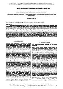
Experiment Based on simulated data
Simulations are conducted to further illustrate the performance of the proposed method. In the simulation, the carrier frequency is 9GHz and bandwidth is 2GHz, the initial distance of the radar to the target is 200km. We can see that the modified method have a better performance than the method directly conducting MTRC on the coarse image. 1500
1500
2000
Range
4 ts 4 f ct 'm yk ,0 j xk ,0 C C t 4 f c 4 f c 4 f c j yk ,0 j x p ,0 1 s t 'm j (t1 ) C C f C c
1 p (m) = small phase modulation produced by clutters
Range
4 ts 4 f ct 'm yk ,0 j xk ,0 C C 4 f c 4 f c fc 4 f c (t1 ) j yk ,0 j x p ,0 t 'm j C C f c ts C
j
2500
2000
2500
3000
3000
80
100
120 140 Azimuth
160
180
80
(a)
4 ts 4 f ct 'm 4 f c yk ,0 j xk ,0 j yk ,0 C C C
4 f c j (t1 ) C 4 ts 4 f ct 'm 4 f c j yk ,0 j xk ,0 j yk ,0 C C C 4 f c j (t1 ) C
120 140 Azimuth
160
180
(b) 1500
(11)
In the practical application, the chosen scattering point could be understood as fitting the prominent point model in which a significant scatter point and small clutters exist in the same
Range
j
100
2000
2500
3000 100
120
140 160 Azimuth
180
200
(c) Figure 2 (a) image obtained by the classic method; (b) image obtained by conducting MTRC on (a); (c) image obtained by the modified method
This contribution has been peer-reviewed. The double-blind peer-review was conducted on the basis of the full paper. https://doi.org/10.5194/isprs-annals-IV-3-61-2018 | © Authors 2018. CC BY 4.0 License.
63
ISPRS Annals of the Photogrammetry, Remote Sensing and Spatial Information Sciences, Volume IV-3, 2018 ISPRS TC III Mid-term Symposium “Developments, Technologies and Applications in Remote Sensing”, 7–10 May, Beijing, China
4.2
proposed method has a better performance than directly implementing MTRC on the coarse image.
Experiment Based on Real data
Real data of the Yak-42 aircraft is processed in a similar way. From Figure 3(c) we can see that scattering points especially those on the nose of the aircraft have been better focused. Figure (4) is the partial enlarged drawing of images obtained by the two methods. It is clear that images on the right side which are obtained by the modified method have a better focus than the two on the left side which are obtained by the classic method. 250
250
300
C.C. Chen, H.C. Andrews. Target-Motion-Induced Radar Imaging, [J] IEEE Transaction on Aerospace Electronic Systems, 1980, 16(1): 2-14. Bao Z, Xing M D, Wang T, Radar imaging, Electronic publishing house, Beijing, 2005.
300
350
350
400
Jiang Z L, Xing M D, Bao Z, correction of migration through resolution cell in ISAR imaging, [J] Journal of Electronics and Information Technology, vol.24, no.1, May 2002
400
450
Azimuth
Azimuth
REFERENCES
500 550
450 500 550
600
600
650
Li X, Liu G S, Ni J L. Autofocusing of ISAR images based on entropy minimization, [J] IEEE Transactions on Aerospace and Electronic Systems, 1999, 35(4): 1240-1251.
650
700
700 600
800
1000 1200 Range
1400
1600
600
800
1000 1200 Range
(a)
1400
1600
(b) Su F L,Cao Z D. Improvements on the range alignment of the motion compensation for ISAR imaging, IEEE International Radar Conference.
250 300 350
Azimuth
400 450
Tor Berger, Svein-Erik Hamran, A two-step maximum likelihood algorithm for ISAR motion compensation, IEEE Radar Conference, 2013
500 550 600 650 700 600
800
1000 1200 Range
1400
1600
(c) Figure 3 (a) image obtained by the classic method; (b) image obtained by conducting MTRC on (a); (c) image obtained by the modified method 420
440 440
Wang J F,Kasilingam D. Global range alignment for ISAR, [J] IEEE Transactions on Aerospace and Electronic Systems, 2003, 39(1): 351 - 357. Wang G L, Zhou D Y, Bo Y X, Modified prominent point processing in ISAR imaging based on minimum entropy method, in the 6th International Symposium on Computational Intelligence and Design, 2013
460
Azimuth
Azimuth
460
480
Yu li, Li Chong-yi. Global correlation envelope alignment of high precision, APSAR, 2007.
480 500
500
520 520
540 540 1250
1300
1350 1400 Range
1450
1500
1300
1350
1400 1450 Range
(a)
1500
1550
(b)
460
480 480
500
Azimuth
Azimuth
500
520
520 540
540
560 560
580 580 650
700
750
800
850
900
700
Range
(c)
750
800 850 Range
900
950
(d )
Figure 4 partial enlarged drawings; image (a) and (c) are right wing and left wing obtained by the original method; image (b) and (d) are obtained by modified method correspondingly 5. CONCLUSIONS A joint processing of motion compensation which links the phase correction and envelope alignment has been presented in this paper. The two reference points discussed are turned into the sole point in the modified method, which truly improves the imaging effects. Simulation and real data processing also showed that conducting MTRC on the image produced by the
This contribution has been peer-reviewed. The double-blind peer-review was conducted on the basis of the full paper. https://doi.org/10.5194/isprs-annals-IV-3-61-2018 | © Authors 2018. CC BY 4.0 License.
64