This algorithm provides a power and rate allocation that is Pareto-optimal and ... In this algorithm, a base-station is assigned to each mobile taking into account the .... At each time slot (this could be a generic interval of time), the power.
1
Joint Resource Allocation and Base-Station Assignment for the Downlink in CDMA Networks Jang Won Lee, Ravi R. Mazumdar, and Ness B. Shroff School of Electrical and Computer Engineering Purdue University West Lafayette, IN 47907, USA {lee46, mazum, shroff}@ecn.purdue.edu
Abstract In this paper, we consider the joint resource allocation and base-station assignment problem for the downlink in CDMA networks with heterogeneous data services. We first study a power and rate control problem that attempts to maximize the expected throughput of the system. This problem is inherently difficult because it is in fact a nonconvex optimization problem. To solve this problem, we propose a distributed algorithm based on dynamic pricing. This algorithm provides a power and rate allocation that is Pareto-optimal and asymptotically optimal. We study the properties of the proposed power and rate allocation and the global optimal power and rate allocation and show that they have similar properties. We also characterize the optimality conditions of pure TDMA and CDMA type of transmissions, which depend not only on the fixed system parameters but also on the channel state and the maximum data rate of each mobile. Finally, using the outcome of the proposed power and rate allocation algorithm, we propose a pricing based base-station assignment algorithm resulting in joint resource allocation and base-station assignment. In this algorithm, a base-station is assigned to each mobile taking into account the congestion level of the base-station as well as the transmission environment of the mobile. We show that it provides higher performance than the SIR based base-station assignment algorithm in which only the transmission environment of the mobile is considered.
I. I NTRODUCTION The increasing demand for high data rate services in wireless networks and scarcity of radio resources necessitate efficient usage of radio resources. Some of the main difficulties in using radio resources efficiently are the time and location dependent channel characteristics and the demand to accommodate mobiles This research has been supported in part by NSF grants ANI-0073359, ANI-9805441, and ANI-0207728.
2
with diverse service requirements. Hence, for the efficient utilization of radio resources, it is necessary to adopt a resource allocation scheme according to the channel status and the service requirements of mobiles. Moreover, if the joint allocation of two or more resources is considered, the performance gain could be significantly increased. Recently, there have been a number of papers that have studied joint resource allocation problems [1], [2], [3], [4], [5], [6], [7]. Oh and Wasserman [1] consider a joint power and spreading gain allocation problem for the uplink in Code Division Multiple Access (CDMA) networks. They consider a single cell system and formulate an optimization problem for a single class of mobiles. Their objective is to maximize the total system throughput of mobiles with a constraint on the maximum transmission power of each mobile. In this work, they do not impose any constraint on the spreading gain (i.e., data rate). They show that for the optimal solution, mobiles are selected for transmission according to the channel state and if a mobile is selected, it transmits at its maximum transmission power. They generalize their algorithm to multi-cellular networks in [2]. Bedekar et al. [3] and Berggren et al. [4] consider joint power and rate allocation for the downlink of the CDMA system with a constraint on the total transmission power for the base-station. However, their models do not consider that each mobile could have a maximum data rate constraint. They show that, for the downlink of the system without the maximum data rate constraint, selecting only one mobile at a time and allocating the total transmission power to that mobile (i.e., the pure Time Division Multiple Access (TDMA) type of strategy) is an optimal strategy. Joint power allocation and base-station assignment problems for the uplink have been considered by Hanly [5] and Yates and Huang [6]. In these papers, the minimum transmission power satisfying the Signal to Interference Ratio (SIR) threshold of each mobile is obtained by joint power allocation and base-station assignment. At each iteration of the algorithm, each mobile is assigned to the base-station that provides the maximum SIR. Saraydar et al. [7] also consider a joint power allocation and base-station assignment problem for the uplink case. They model the problem as an N -person non-cooperative power allocation game. Each mobile selects the optimal power level and the base-station that maximizes its net utility, (i.e., utility minus cost) without considering other mobiles. The performance of their algorithm depends on the choice of the price. However, they do not provide a strategy of how to determine the optimal price. In this paper, we study a joint resource allocation and base-station assignment problem for CDMA networks. We focus on the downlink problem in this paper, since the downlink is typically considered a bottleneck due to the asymmetric bandwidth demand between the downlink and the uplink for data services [8],
3
[9], [10], [11]. We first consider a joint power and rate allocation problem by focusing on one cell of the system. Power is the most important resource in CDMA networks. By increasing the transmission power level of a specific mobile, the performance of the mobile can be improved. But this increase in transmission power also deteriorates the performance of the other mobiles, since it produces more interference to other mobiles. Hence, the power allocation among mobiles is an important resource allocation problem in CDMA networks. Further, there is a trade off between the data rate and Eb /I0 (bit energy to interference density ratio) that is related to the transmission success probability. At a given transmission power level, if the data rate is increased, Eb /I0 is decreased and vice versa. Therefore, by jointly optimizing the allocation of power and data rate, the throughput of the system can be improved significantly. In this paper, the goal of the joint power and rate allocation is to maximize the total expected system throughput. We allow for constraints on the total transmission power at the base-station and the maximum data rate for each mobile. It turns out that this problem is a non-convex programming problem. In general, obtaining a global optimal solution of a non-convex programming problem is not easy and requires a complex algorithm. Hence, in this paper, we propose a simple distributed power and rate allocation algorithm that provides a Pareto-optimal power and rate allocation as well as an asymptotic optimal power and rate allocation. We also study the properties of power and rate allocation in the downlink of the system in the presence of the constraint on the maximum data rate and heterogeneous mobiles. As mentioned above, it was proven that, for the downlink in the idealized system in which there is no constraint on the maximum data rate for each mobile, the optimal strategy is to transmit only one mobile at a time. In addition, it can be easily shown that if all mobiles are homogeneous, transmitting a mobile in the best transmission environment is an optimal strategy. However, in practice, due to either the physical limit of the hardware or the application limit, each mobile cannot receive more than some maximum data rate and there exists a constraint on the maximum data rate. Further, it is possible that each mobile has a different modulation scheme and a different coding level that depend on the channel state and the application [12]. In this case, each mobile has a different function fi , since it depends on the modulation and the coding schemes. Because of these two generalizations (that are practically important), a strategy that transmits only one mobile in the best transmission environment may not be optimal. In this paper, we characterize the optimality conditions for pure CDMA type of transmission in which the base-station transmits to all mobiles simultaneously and pure TDMA type of transmission in which the base-station transmits to only one mobile at a time, when there exists a constraint on the maximum data rate for each mobile. We also study the properties of our
4
mobile selection strategy, when there are heterogeneous mobiles in the system. We next consider a multi-cellular system. Here we propose a pricing based base-station assignment algorithm. In the traditional SIR based base-station assignment, a mobile is assigned the base-station that can transmit to it at the highest SIR. Hence, in this scheme, only the transmission environment (the channel state and the interference level) between a base-station and a mobile is considered in determining which basestation should communicate to a mobile. However, when a cell is congested, by reassigning some of the mobiles in the cell to other cells that are less congested, we can expect to improve the system performance by balancing the load of cells. Therefore, when a base-station is assigned to a mobile, by taking into account the congestion level of the cell as well as the transmission environment of the mobile, we can significantly improve the performance of the system. However, obtaining optimal assignment of base-stations may need complicated algorithm to be implemented in practice, since it may require global coordinations among basestations. Hence, we propose a heuristic and simple algorithm in this paper. To measure the congestion level in the cells and the transmission environment of mobiles, we will use the outcomes of the proposed power and rate allocation algorithm in this paper. Our base-station assignment algorithm has two distinguishing features compared with base-station assignment algorithms proposed in [5], [6], [7]. First, it is simple and needs less signaling costs than the other algorithms. In our algorithm, each mobile needs only base-stationspecific information that can be broadcasted from the base-station, while in other algorithms, each mobile needs mobile-specific information that requires for the base-station to maintain signaling channels with not only mobiles in its own cell but also mobiles in other cells. Second, our algorithm is based on the downlink performance, while others are based on the uplink performance. As mentioned before, in wireless networks, the downlink is the bottleneck link. Hence, base-station assignment based on downlink performance may be a more appropriate approach. In many problems in wireless networks, the algorithm for the uplink can be used for the uplink with simple modifications. However, as shown in [13], in the joint power allocation and base-station assignment problems, the uplink problem and the downlink problem have different properties. This implies that the algorithm for the uplink cannot be easily modified for the use in the downlink, which necessitates the study of the downlink problem independently. The rest of the paper is organized as follows. In Section II, we describe the system model. We present the joint power and rate allocation algorithm in Section III and study the properties of power and rate allocation in Section IV. In Section V, the base-station assignment algorithm is presented. We provide numerical results using computer simulation in Section VI and conclude in Section VII.
5
II. S YSTEM MODEL We consider the downlink in a CDMA network consisting of B base-stations (cells) and M mobiles. The system is assumed to be time-slotted. At each time slot (this could be a generic interval of time), the power and data rate allocation algorithm and the base-station assignment algorithm are executed. A time slot in our system is an arbitrary interval of time and could consist of one packet or several packets. Each base-station has its maximum power limit PT and each mobile communicates with one base-station. For a given mobile i, Rimax is the maximum data rate at which it can receive and fi is the probability of packet transmission 4
success, which is a function of γi = Eb /I0 (bit energy to interference density ratio) for mobile i and depends on the modulation and coding level. We can express γi for mobile i that communicates with base-station b as: γi (Ri , P¯ (b)) =
W Gi (b)Pi X Ri θGi (b) Pm − θGi (b)Pi + Ii (b) m∈M (b)
=
W Pi X Ri θ Pm − θPi + m∈M (b)
=
Ii (b) Gi (b)
Pi W X , Ri θ Pm − θPi + Ai (b) m∈M (b)
where W
: Chip rate.
θ
: Orthogonality factor.
Pi
: Allocated power for mobile i.
Ri
: Data rate for mobile i.
P¯ (b) : Power allocation vector for mobiles that communicate with base-station b. Gi (b) : Path gain from base-station b to mobile i. Ii (b) : Background noise and intercell interference to mobile i that communicates with base-station b. M (b) : Set of mobiles that communicate with base-station b. Ai (b) : Ii (b)/Gi (b). We assume that fi has the following properties. Assumptions: (a) fi is an increasing function of γi . (b) fi is twice continuously differentiable.
6
(c) fi (0) = 0. (d)
∂ 2 fi (γi ) W ( Ri ∂γi2
(e) If
i (γi ) + θγi ) + 2θ ∂f∂γ = 0 has at most one solution for γi > 0. i
∂ 2 fi (γi ) W ( Ri ∂γi2
γi < γio and
i (γi ) + θγi ) + 2θ ∂f∂γ = 0 has one solution at γio > 0, i
∂ 2 fi (γi ) W ( Ri ∂γi2
P
i∈M (b)
In addition, if it has an inflection point Pio , then P
i∈M (b)
i (γi ) + θγi ) + 2θ ∂f∂γ > 0 for i
i (γi ) + θγi ) + 2θ ∂f∂γ < 0 for γi > γio . i
Remark 1: By the assumptions above, if
We will show that
∂ 2 fi (γi ) W ( Ri ∂γi2
Pi is constant,
∂2f
i (γi ) ∂Pi2
∂ 2 fi (γi ) ∂Pi2
has at most one inflection point.
> 0 for Pi < Pio and
∂ 2 fi (γi ) ∂Pi2
< 0 for Pi > Pio .
Pi = PT later. Therefore, fi can be one of three types: a sigmoidal-like function
of its own power allocation1 , a concave function of its own power allocation, or a convex function of its own power allocation. In most cases, the probability of packet transmission success can be characterized by one of these three types of functions. In Fig. 1, we provide some examples for Binary Phase-Shift Keying (BPSK), Differential Phase-Shift Keying (DPSK), and Frequency-Shift Keying (FSK) modulation schemes. In this figure, we assume a packet consists of 800 bits without channel coding and set PT = 10, θ = 1, W Ri
= 16, and Ai (b) = 0.7407.
III. P OWER
AND RATE ALLOCATION
In this section, we study the power and data rate allocation problem focusing on one cell of the system. For notational convenience, we will omit the parameter for the base-station in variables. We assume that mobiles from 1 to M communicate with their target base-station. First, we define Ui , the utility function of 1
A sigmoidal-like function means a function fi (x) that has one inflection point, xo and
d2 fi (x) dx2
> 0 for x < xo and
d2 fi (x) dx2
i.e. fi (x) is a convex function for x < xo and a concave function for x > xo .
1 0.8
f(P)
0.6 0.4 BPSK DPSK FSK
0.2 0 0
2
4
P
6
8
10
Fig. 1. Probabilities of packet transmission success for BPSK, DPSK, and FSK modulation schemes.
< 0 for x > xo ,
7
mobile i as Ui (Ri , P¯ ) = Ri fi (γi (Ri , P¯ )),
i = 1, 2, · · · , M,
(1)
which is the expected throughput of mobile i. Then, the optimization problem for power and rate allocation considered in this paper is given by (A)
max
M X
Ui (Ri , P¯ )
i=1
subject to
M X
Pi ≤ PT ,
i=1
0 ≤ Pi ≤ PT ,
i = 1, 2, · · · , M,
0 ≤ Ri ≤ Rimax ,
i = 1, 2, · · · , M.
Therefore, our goal is to maximize the total expected system throughput (the sum of the expected throughput of all mobiles) with constraints on the total transmission power at the base-station and the maximum data rate for each mobile. To solve problem (A), we first calculate the optimal data rate given a power allocation and, next, obtain the power allocation. It can easily be shown that, to maximize the total system throughput, the base-station must transmit at its maximum power limit, PT . This implies that
PM
i=1
Pi = PT and
W Pi γi (Ri , P¯ ) = M Ri X θ Pm − θPi + Ai m=1
Pi W = Ri θPT − θPi + Ai 4
= γi (Ri , Pi ),
i = 1, 2, · · · , M.
Note that γi (Ri , Pi ) does not depend on the power allocation for other mobiles and we can rewrite the utility function for mobile i defined in Equation (1) as Ui (Ri , Pi ) = Ri fi (γi (Ri , Pi )),
(2)
which does not depend on the power allocation for other mobiles. Therefore, each mobile i can determine Ri∗ (Pi ), the optimal data rate for a given power allocation Pi without considering the other mobiles. The optimal data rate for mobile i for a given power allocation is obtained by the following proposition.
8
Proposition 1: For the power allocation Pi , Ri∗ (Pi ), the optimal rate for mobile i, is given by
Ri∗ (Pi )
=
Rimax γi∗ (θPT +Ai ) , W +θRimax γi∗
W Pi , γi∗ (θPT −θPi +Ai )
if Pi ≤
Rimax ,
otherwise,
where γi∗ = arg maxγ≥1 { γ1 fi (γ)}. Proof: See Appendix A. From Proposition 1 and Equation (2), the utility function of mobile i at the optimal data rate allocation for a given power allocation, Pi , Ui (Ri∗ (Pi ), Pi ) is expressed as R∗
4
Ui i (Pi ) = Ui (Ri∗ (Pi ), Pi )
=
Pi W f (γ ∗ ), γi∗ θPT −θPi +Ai i i
if Pi ≤
Rimax γi∗ (θPT +Ai ) , W +θRimax γi∗
(3)
Rmax f (γ (Rmax , P )), otherwise, i i i i i
and problem (A) is equivalent to the following optimization problem.2 (B)
max
M X i=1
R∗
Ui i (Pi )
subject to
M X
Pi ≤ PT ,
i=1
0 ≤ Pi ≤ PT ,
i = 1, 2, · · · , M.
In problem (B), the problem is reduced to a power allocation problem from the original power and rate allocation problem. After obtaining the appropriate power allocation by solving problem (B), the optimal transmission data rate can be obtained via Proposition 1. R∗
Remark 2: In Equation (3), Ui i (Pi ) is a convex function for Pi ≤ Ri∗
Ui (Pi ) follows the shape of fi for
Rimax γi∗ (θPT +Ai ) W +θRimax γi∗
Rimax γi∗ (θPT +Ai ) W +θRimax γi∗
and the shape of
Ri∗
< Pi ≤ PT . Therefore, Ui (Pi ) is a convex function,
or a sigmoidal-like function of Pi , since by assumption, fi is a convex function, a concave function, or a sigmoidal-like function of Pi . Ri∗
Since Ui
could be a sigmoidal-like function, which is the more interesting case, in general, it is not easy
to obtain an optimal solution for problem (B). However, it turns out that the structure of problem (B) is similar to that of the problem studied in [14]. In [14], a power allocation algorithm that provides a power allocation that is Pareto-optimal as well as a good approximation of the global optimal power allocation 2
A mobile with the fixed data rate Rf can be easily accommodated in this problem, if we assume that Ri∗ (Pi ) = Rf for 0 ≤ Pi ≤ PT .
9
for sigmoidal-like, convex, and concave utility functions. Further, it is proved that the power allocation is asymptotically optimal in [15]. We can hence exploit the power allocation strategy in [14] to obtain a Pareto-optimal and asymptotically optimal power allocation and obtain the optimal data rate for the power allocation using Proposition 1. In the following, we briefly describe the power allocation algorithm. We refer readers to [14], [15] for more details. The power allocation algorithm is a dynamic pricing based algorithm. The base-station broadcasts λ, the price per unit power to all mobiles that communicate with it. Based on λ, each mobile i requests a power level Pi (λ) that maximizes its net utility, i.e., R∗
Pi (λ) = arg max {Ui i (P ) − λP }. 0≤P ≤PT
(4)
Based on the amount of power requested by all mobiles, the base-station updates λ to maximize the total system utility. The algorithm consists of two stages, the mobile selection stage and the power allocation stage. At the mobile selection stage, mobiles are selected by the mobile selection algorithm: Mobile Selection Algorithm (a) If P1 (λmax ) = PT , mobile 1 is selected. 1 (b) If (c) If (d) If
Pk−1 j=1
Pk−1 j=1
PM
j=1
Pj (λmax k−1 ) < PT and Pj (λmax ) < PT and k
Pk−1
Pj (λmax ) ≥ PT , mobiles 1, 2, · · · , k − 1 are selected. k
j=1
Pk
j=1
Pj (λmax ) > PT , mobiles 1, 2, · · · , k − 1 are selected. k
Pj (λmax M ) ≤ PT , mobiles 1, 2, · · · , M are selected.
where λmax is the maximum willingness to pay per unit power of mobile i and is defined as i R∗
λmax = arg min { max {Ui i (P ) − λP } = 0}, i 0≤λ≤∞ 0≤P ≤PT
max and we assume that λmax > λmax > · · · > λmax the maximum willingness to pay per unit 1 2 M . We call λi
power of mobile i, since Pi (λ) > 0 for λ ≤ λmax and Pi (λ) = 0 for λ > λmax . Therefore, at the mobile i i selection stage, mobiles are selected in a decreasing order of λmax as many as possible satisfying the power i constraint. Each mobile i can calculate λmax as: i
λmax = i
R∗
∂Ui i (P ) |P =P ∗ , ∂P R∗ Ui i (PT )
PT
,
if 0 < Pio < PT and P ∗ exists, otherwise,
R∗
where Pio is an inflection point of Ui i (P ) and P ∗ is a solution of the following equation. R∗ Ui i (P )
R∗
∂U i (P ) −P i = 0, ∂P
Pio ≤ P ≤ PT .
(5)
10
After selecting mobiles, the problem is reduced to a convex programming problem. Thus, at the power allocation stage, power is allocated optimally to the selected mobiles using a simple algorithm. In [14], the power allocation algorithm was implemented using a bisection algorithm. It was shown that if a condition in either (a), (b), or (d) of the mobile selection algorithm is satisfied, the power allocation is a global optimal power allocation. But, if the condition in (c) of the mobile selection algorithm is satisfied, the power allocation might be different from the global optimal power allocation. IV. S TUDY OF THE PROPOSED POWER AND RATE ALLOCATION ALGORITHM A. Mobile selectivity We study the properties of the mobile selectivity in this subsection. Recall that Ai is defined by Ii /Gi , where Ii is background noise and intercell interference to mobile i and Gi is path gain from the base-station to mobile i, fi is the probability of packet transmission success for mobile i, and Rimax is the maximum data rate for mobile i. Thus, Ai represents the degree of “goodness” of the transmission environment from the base-station to mobile i. Smaller Ai implies that a better transmission environment. ≥ λmax and mobile The next proposition shows that if mobile i is more efficient than mobile j, then λmax i j i has a greater chance to be selected by the algorithm than mobile j. This is the case because in the mobile selection algorithm, mobiles are selected in a decreasing order of λmax . As pointed out in the previous i section, the power allocation is a global optimal power allocation for the selected mobiles. Therefore, with this efficient mobile selection combined with the globally optimal power allocation for the selected mobiles, our algorithm can achieve high efficiency of the system. We first define the efficiency of mobiles. R∗
R∗
Definition 1: Mobile i is said to be more efficient than mobile j if Ui i (P ) ≥ Uj j (P ) for 0 ≤ P ≤ PT . Proposition 2: If mobile i is more efficient than mobile j, then λmax ≥ λmax . i j Proof: See Appendix B.
Corollary 1: Suppose fi (γ) = fj (γ) and Ai = Aj . Then, if Rimax > Rjmax , λmax ≥ λmax . i j Proof: See Appendix C. Corollary 1 implies that if other conditions are same, the mobile with a higher maximum data rate has a higher priority to be selected than the mobile with a lower maximum data rate. Corollaries 2 and 3 can be proved in a similar way to Corollary 1.
11
Corollary 2: Suppose Rimax = Rjmax and Ai = Aj . Then, if fi (γ) ≥ fj (γ) for all γ, λmax ≥ λmax . i j In Corollary 2, fi (γ) ≥ fj (γ) implies that mobile i needs a lower value of Eb /I0 to achieve the same transmission success probability as mobile j, i.e., mobile i has a more efficient transmission scheme than mobile j. Hence, Corollary 2 implies that if other conditions are same, the mobile with the more efficient transmission scheme has a higher priority to be selected than the mobile with the less efficient transmission scheme. ≥ λmax . Corollary 3: Suppose fi (γ) = fj (γ) and Rimax = Rjmax . Then, if Ai < Aj , λmax i j In Corollary 3, Ai < Aj implies that mobile i is in a better transmission environment than mobile j. Hence, if other conditions are same, a mobile in a better transmission environment has a higher priority to be selected than a mobile in a worse transmission environment. This also implies that if all mobiles are homogeneous, then mobiles are selected in an increasing order of Ai , i.e., mobiles are selected according to their transmission environment. It can be easily shown that the results in this subsection can be applied to the global optimal power and rate allocation. Therefore, in the system with heterogeneous mobiles, the mobile selectivity depends not only on the transmission environment of mobiles but also on the maximum data rate and the transmission scheme of mobiles. This implies that, in general situations in which several conditions are mixed, it is not easy to determine which mobiles must be selected for the global optimal solution. However, our mobile selection that selects mobiles in a decreasing order of λmax provides a simple and unified strategy of mobile i selection, while providing a good approximation of the global optimal solution.
B. Properties of the proposed power and rate allocation In this subsection, we study properties of the proposed power and rate allocation. The next proposition gives us the optimal transmission data rate of the selected mobiles. Proposition 3: Suppose that mobile i is selected by the mobile selection algorithm, then Ri∗ , the transmission data rate for mobile i is given by
Ri∗ = Proof: See Appendix D.
PT W γi∗ Ai
< Rimax , if Ai >
Rimax ,
PT W , Rimax γi∗
otherwise.
12
Proposition 3 implies that each mobile can compute its transmission data rate when it is selected by the proposed power and rate allocation algorithm before the power allocation procedure, since Ri∗ does not depend on the individual power level Pi . This is true even though the optimal data rate of a mobile is a function of the level of the power allocation, as shown in Proposition 1. From the proof of Proposition 3, R∗
if Ri∗ < Rimax , Ui i (P ) is a convex function and mobile i is allocated the total transmission power PT at price λ∗ = λmax . This implies that if a mobile is selected for transmission, it is always allocated the data i rate either Ri∗ = Rimax that is a constant or Ri∗ < Rimax that requires the total transmission power PT . Thus, we can think that Ri∗ does not depend on the individual power level Pi . Using this property, mobile i can calculate its transmission data rate Ri∗ after measuring its transmission environment Ai and it can act like a mobile with a fixed data rate Ri∗ during the power allocation procedure. We also have the next corollary that indicates that the joint power and data rate allocation for a mobile using the proposed algorithm is one of boundary points of the individual constraint set of the mobile. Corollary 4: If mobile i is selected by the mobile selection algorithm and Ri∗ < Rimax , only mobile i is selected and the total power is allocated to it. Corollary 4 implies that at most one mobile can be allocated a data rate that is smaller than its maximum data rate. Further, if there exists such a mobile, other mobiles cannot be selected. Therefore, if we assume that mobiles are selected sequentially (in a decreasing order of the maximum willingness to pay) in the proposed scheme, a new mobile can be selected, only when both the mobiles that are already selected and the new mobile can be allocated their maximum data rates. A similar result can be shown for the global optimal power and rate allocation. ∗ ) is a global power allocation, then at most one mobile achieves Proposition 4: If P¯ ∗ = (P1∗ , · · · , PM
utility value in the convex region of the utility function among the selected mobiles for transmission. Proof: See Appendix E. Proposition 4 implies that at the global optimal power and rate allocation, at most one mobile can be allocated a data rate that is smaller than its maximum data rate (similar to the case in our scheme), since at the concave region of the utility function, a mobile is allocated its maximum data rate. If some mobile, that is allocated a smaller data rate than its maximum data rate, is selected for transmission along with other mobiles, we can think that this mobile utilizes power most inefficiently among the selected mobiles. This has to be true, otherwise, by taking some power from the other mobiles and allocating it to the mobile, we can increase its
13
data rate up to the maximum data rate and improve the overall system performance. Hence, if we assume that mobiles are selected for transmission sequentially (in a decreasing order of the efficiency of power utilization) at the global optimal power and rate allocation, a new mobile can be selected, only when mobiles that are already selected can be allocated their maximum data rate as in our scheme. But in the global optimal scheme, a new mobile can be allocated a data rate that is smaller than its maximum data rate, which is not allowed in our scheme. Therefore, we can infer that if we have a situation when a mobile is in the convex region at the global optimal power and rate allocation, the proposed algorithm does not allocate power to the mobile but distributes power to be allocated to the mobile to the other selected mobiles optimally. As pointed out before, in general, the mobile in the convex region at the global optimal power and rate allocation utilizes power less efficiently than the other selected mobiles and the utility value in the convex region is relatively small. But finding the mobile in the convex region at the global optimal power and rate allocation is not easy. Hence, by ignoring the mobile that is relatively inefficient, we can obtain a good approximation of the global power and rate allocation with the simple proposed algorithm.
C. Study of the optimality conditions for TDMA and CDMA type of transmissions In this subsection, we study the optimality conditions of pure TDMA type of transmission that transmits to only one mobile at a time and pure CDMA type of transmission that transmits to all mobiles simultaneously. The next proposition gives us the optimal conditions for the TDMA type of transmission and the CDMA type of transmission. Proposition 5:
) ≥ PT , where λmax > λmax > · · · > λmax (a) If P1 (λmax 2 1 2 M , then selecting only mobile 1
and allocating the total transmission power to it is an optimal strategy. (b) If
PM
i=1
max Pi (λmax > λmax > · · · > λmax M ) ≤ PT , where λ1 2 M , then selecting all mobiles and transmit-
ting to all mobiles simultaneously is an optimal strategy. Proof: See Appendix F. Note that the optimality conditions in Proposition 5 depend not only on system parameters that are constant, but also on the transmission environment of each mobile (time varying and location dependent) and the maximum data rate of each mobile (also time varying from the point of view of the system). Moreover, selecting a subset of mobiles at a time and transmitting only to them can be an optimal strategy depending
14
on the system status. This implies that a static strategy for transmission could be inefficient in some cases and to obtain a high efficiency of the system, we need a strategy that can be adapted to dynamic characteristics of the system, such as the scheme proposed in this paper. From Proposition 5 (a), we can also infer that if Rimax >
PT W Ai γi∗
for all mobiles (i.e., if mobiles have a high
enough maximum data rate or the transmission environment of mobiles is bad because of high interference or high channel loss), then pure TDMA type of transmission is optimal. In this case, Ri∗ < Rimax for all R∗
mobiles by Proposition 3 and Ui i (P ) is a convex function for each mobile i that has Pi (λmax ) = PT . i Therefore, by Proposition 5 (a), selecting only one mobile and allocating the total transmission power to it is an optimal strategy. This also implies that if there is no constraint on the maximum data rate for mobiles, then TDMA type of transmission is always optimal regardless of transmission environment of mobiles as shown in [3], [4].
V. BASE - STATION ASSIGNMENT In the previous sections, we considered a power and rate allocation problem by focusing on one cell of the system. In this section, we consider a multi-cellular system and it brings us two additional problems that were not considered in the previous sections. One is the total transmission power allocation problem for each base-station and the other is the base-station assignment problem for each mobile. To maximize the improvement of the system performance, the power allocation for base-stations must be done considering the status of each cell and and the channel state of each mobile. But, in practice, this would require a very complex power allocation algorithm, since it needs the cooperation among base-stations (at least among adjacent base-stations). In addition, each base-station may require information not only from mobiles in its cell, but also from mobiles in other cells, resulting in a significant amount of signaling cost. For instance, Oh et al. extend their power control and spreading gain allocation algorithm for a single cell system [1] to a multi-cellular system [2]. To perform the algorithm, each base-station needs to know the detailed information of the status of the mobiles in its own cell and adjacent cells. However, even with this significant amount of information, the algorithm is not guaranteed to converge to the optimal allocation and requires much longer convergence time than the algorithm for the single cell system. Therefore, in this paper, we adopt a strategy that each base-station tries to maximize its total system utility without considering the status of other cells. Using this strategy, each base-station performs the power allocation algorithm in the previous section by independently transmitting at its maximum power
15
level, which makes the algorithm simple. This is typically called a non-cooperative situation and results in a Nash equilibrium operating point, which might be inefficient, i.e., there might exist another total power allocation with which each mobile can obtain higher utility than the Nash equilibrium power allocation. If the load of each cell is unbalanced, the inefficiency might be large. For example, if one cell is heavily loaded and an adjacent cell is lightly loaded, by decreasing the total transmission power of the base-station in the lightly loaded cell, interference for mobiles in the heavily loaded cell can be decreased. This results in a decrease of the utility of the lightly loaded cell and an increase in the utility of the heavily loaded cell. In such a case, generally, the increase can be larger than the decrease in utility and hence the total system utility could be higher than the total system utility at the Nash equilibrium. To cope with this situation, we propose a base-station assignment algorithm. By reassigning some mobiles in the heavily loaded cells to lightly loaded cells, we can expect to improve the total system utility by balancing the load among the base-stations. We next describe the proposed base-station assignment algorithm. Each base-station performs the power and data rate allocation algorithm in the previous section independently. For the base-station assignment, we use the results of the power and data rate allocation algorithm, which is a pricing based algorithm. Thus, we call our base-station assignment the pricing based base-station assignment. We first define some variables. •
S c (b): Set of mobiles that are not selected for transmission by base-station b among mobiles that communicate with base-station b.
•
λmax (b): Maximum willingness to pay per unit power of mobile i for base-station b. i
•
λ∗ (b): Equilibrium price per unit power for base-station b.
•
w(b) =
maxi∈S c (b) {λmax (b)}, i
if S c (b) 6= φ,
0,
otherwise.
Also, recall that Ai (b) indicates the transmission environment between base station b and mobile i. Smaller Ai (b) indicates a better transmission environment. Assume that mobile i is currently communicating to base-station b. If mobile i is selected for transmission by base-station b, it continues to communicate to base-station b in the next time slot. But, if mobile i is not selected for transmission by base-station b, at the next time slot, it selects and connects to a base-station d that satisfies d = arg max {λmax (k) − λ∗ (k)}, i k∈g(i)
(6)
16
where g(i) = {k ∈ B|λmax (k) ≥ w(k)} i
(7)
and B is the set of base-stations. Note that B may not be the set of all base-stations. It could be a subset of all base-stations. For example, B could be the set of adjacent base-stations of base-station b or the set of base-stations from which mobile i receives pilot signal with enough strength. If w(b) > λmax (b), mobile i i cannot be selected by base-station b and in Equation (7), we exclude base-station b ∈ B from g(i) whose w(b) is larger than λi (b). Therefore, g(i) can be thought as the set of candidate base-stations by which mobile i can be selected. By Equation (6), the mobile selects a base-station that has the maximum value of the maximum willingness to pay for the base-station minus the equilibrium price of the base-station among the candidate base-stations. We can explain the intuition of the proposed algorithm using two interpretations. First, from the point of view of pricing, we can think that the mobile selects the base-station which gives it the highest profit per unit power. Since λmax (b) can be interpreted as the maximum value for unit power of mobile i at base-station i b and λ∗ (b) can be interpreted as the current price for unit power at base-station b, λmax (b) − λ∗ (b) can be i interpreted as the profit per unit power that mobile i can obtain if it is selected by base-station b. Another interpretation is that the mobile selects the base-station with which it has the relatively best transmission environment considering the congestion level of the base-station. The next proposition tells us that λmax (b) i is an indicator of the transmission environment between base-station b and mobile i. Proposition 6: If λmax (n) < λmax (m), then Ai (n) > Ai (m). i i Proof: See Appendix G. By the definition of Ai (b), λmax (n) < λmax (m) implies that the transmission environment between basei i station m and mobile i is better than the transmission environment between base-station n and mobile i. Thus, λmax (b) can be interpreted as the “goodness” of the transmission environment of mobile i when it is i connected to base-station b. Also, we can interpret λ∗ (b) as being the congestion level at base-station b from the following propositions. Proposition 7: Suppose mobile i is selected by base-station n and mobile j is selected by base-station m. Further suppose that fi = fj , Rimax = Rjmax , and Ai (n) = Aj (m). Then, if λ∗i (n) < λ∗j (m), Pi (λ∗ (n)) ≥ Pj (λ∗ (m)). Proof: See Appendix H.
17
What Proposition 7 tells us is that if two mobiles are in the same condition and they are selected by different base-stations, a mobile in the base-station with a lower equilibrium price is allocated more power than a mobile in the base-station with a higher equilibrium price. In other words, the base-station with a higher equilibrium price has more demand for power than the base-station with a lower equilibrium price. Thus, (b) − λ∗ (b) in Equation we can interpret λ∗ (b) as being the congestion level of base-station b. Hence, λmax i (6) can be interpreted as the relative “goodness” of the transmission environment between mobile i and base-station b, taking into account the congestion level of the cell. From this interpretation, Equation (6) implies that mobile i is reassigned to base-station d which has the relatively best transmission environment considering the congestion level of the cell among the candidate base-stations from which it can be selected. To perform the base-station assignment algorithm in Equations (6) and (7), mobile i must calculate λmax (b) and know λ∗ (b) and w(b) for b ∈ B. Mobile i can calculate λmax (b), if it knows Ai (b) and PT i i and Ai (b) can be measured at mobile i. Hence, the information that mobile i needs to perform the algorithm are PT , λ∗ (b) and w(b) for b ∈ B and these parameters must be transmitted from base-station b. But this is base-station-specific information not mobile-specific information and this can be broadcasted by each base-station. In contrast, for the algorithms in [5], [6], [7], each mobile needs to know some mobile-specific information that must be transmitted from the base-stations that are candidates for the assignment, requiring each mobile to maintain its own signaling channels with several base-stations. Therefore, our algorithm needs less signaling costs than the algorithms in [5], [6], [7]. VI. N UMERICAL RESULTS In this section, we provide numerical results of our power and rate allocation algorithm and base-station assignment algorithm by computer simulations. We also compare the performance of our algorithms with the performance of Qualcomm’s HDR [8], [9], which is proposed for downlink transmission for high data rate services. In HDR, each base-station transmits a pilot signal. Each mobile measures its received SIR from the pilot signals of several base-stations and is connected to the base-station with the highest SIR. At each base-station, for downlink transmission, the base-station transmits at the maximum power, if there is at least one mobile to transmit to, without considering the status of other cells. The downlink transmissions are time multiplexed and at each time slot, each base-station transmits to only one mobile. Therefore, ignoring fairness, the optimal strategy that maximizes the throughput in HDR is to transmit to a mobile that can achieve the highest expected throughput. We adopt this strategy to obtain the performance of HDR, since in this paper, we do not consider fairness.
18
BS
BS
BS
BS
BS
BS
BS
BS
BS
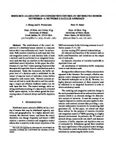
Fig. 2. Cellular network model.
TABLE I PARAMETERS FOR THE SYSTEM .
Maximum power (PT )
10
Chip rate (W )
100000
Distance loss exponent (α)
4
Variance of log-normal distribution (σ 2 )
8
Length of the side of the cell
1000
For the simulation, we model the cellular network with 9 square cells as shown in Fig. 2. We assume that the base-station is located at the center of each cell. We model the path gain from a base-station i to a mobile j, Gi,j as Gi,j =
Ki,j , dαi,j
(8)
where di,j is the distance from the base-station i to mobile j, α is a distance loss exponent and Ki,j is the lognormally distributed random variable with mean 0 and variance σ 2 (dB), which represents shadowing [16]. The parameters for the system are summarized in Table I. For the simulation, we use a sigmoid function to represent fi (γ). The sigmoid function is expressed as fi (γ) = ci { where we set ci =
1+eai hi eai hi
and di =
1 1+eai hi
1 1+
e−ai (γ−hi )
for the normalization.
− di },
(9)
19
TABLE II T HE PROBABILITY OF PACKET TRANSMISSION SUCCESS (a = 3, h = 3.5).
γ(dB) f (γ)
5
6
7
0.2662 0.8089 0.9894
8 0.9998
We first present the performance of the power and rate allocation algorithm without considering basestation assignment. We focus on the cell at the center of the system and assume that the base-stations in other cells transmit at the maximum power limit. In Tables III - V, we assume that there are two classes of mobiles and set the orthogonality factor, θ = 1. In Tables III - IV, we have 10 mobiles that are located independently according to a uniform distribution and mobiles in each class are generated with probability 0.5. In Table III, each class is assumed to have the same fi (γ) = f (γ) but different Rimax . For f (γ), we set a = 3 and b = 3.5 and the values of it for several γ’s are provided in Table II. We provide simulation results by setting R2max = 6250 (N2min = 16) and varying R1max (N1min ). First, the selection ratio of mobiles of each class is provided. The results in Table III indicate that the class with the higher Rimax has a higher selection ratio of mobiles than the class with the lower Rimax . This implies that the proposed power and rate allocation gives a higher priority to be selected to mobiles with the higher maximum data rate, as proved in Corollary 1. We also provide the system utilities obtained by the proposed power and rate allocation and HDR, and the ratio of their utilities. When R1max = 25000, these two algorithms give almost the same utility. This is because if there exist mobiles with high maximum data rate, the optimal strategy is to select one mobile and TABLE III C OMPARISON OF PERFORMANCES OF OUR POWER AND RATE ALLOCATION AND HDR.
R1max
1562.5
3125
6250
12500
25000
(N1min )
(64)
(32)
(16)
(8)
(4)
Selection ratio of class 1
0.50052
0.427702
0.388386 0.347643
0.197597
Selection ratio of class 2
0.567581
0.509915
0.391784 0.121819
0.0197844
Utility (Our algorithm)
21324.7
22298.9
24085.7
25379.3
25307.1
Utility (HDR)
6243.77
6247.18
6250
12485.8
24919
Utility (Our algorithm)/Utility (HDR)
3.41536
3.56944
3.85372
2.03265
1.01557
20
TABLE IV C OMPARISON OF PERFORMANCES OF OUR POWER AND RATE ALLOCATION AND HDR.
h1
2.5
3.0
Selection ratio of class 1
0.565704
0.471902
0.391296 0.306037
0.230125
Selection ratio of class 2
0.288467
0.320855
0.388662 0.448649
0.484367
Utility (Our algorithm)
26222.5
24570.6
24077.7
23196.7
22031.6
Utility (HDR)
6250
6250
6250
6250
6250
Utility (Our algorithm)/Utility (HDR)
4.1956
3.93129
3.85243
3.71148
3.52505
3.5
4.0
4.5
allocate the total transmission power to that mobile. However, as R1max decreases, the utility achieved by our power and rate allocation becomes much higher than that of HDR. The reason for this is that if R1max is not high, the optimal strategy is to select several mobiles and transmit to them simultaneously. From the results, we know that HDR is optimized only for high data rate services and it could be very inefficient, if there exist heterogeneous services, while our algorithm can be used in any cases with high efficiency. In Table IV, numerical results are provided by varying h1 . We set R1max = R2max = 6250 (N1min = N2min = 16), a1 = a2 = 3, and h2 = 3.5. As presented in this table, the class with the lower value of hi has a higher selection ratio than the class with the higher value of hi . By Equation (9), the mobile with the lower hi needs the lower SIR to achieve the same probability of packet transmission success than the mobile with the higher hi . Hence, the former has the more efficient transmission scheme and a higher priority to be selected than the latter, as proved in Corollary 2. We also compare the performance of the proposed power and rate allocation and HDR. From the results, we know that as h1 decreases the difference between the two algorithms gets larger. Hence, the results indicates that as mobiles get more efficient, the base-station can select more mobiles and transmit them simultaneously to improve the system throughput. In table V, we assume that each class has the same maximum data rate, Rimax = 6250, and the same function for the probability of packet transmission success, fi = f . We set a = 3 and b = 3.5. But we divide the cell into two regions: an inner region that is a square at the center of the cell whose length of the side is a half of the length of the side of the cell and an outer region that is the remaining region of the cell. We say that mobiles in the inner region belong to class 1 and the mobiles in the outer region belong to class 2. Thus, a mobile in class 1 is closer to the base-station than a mobile in class 2 and, in general, the former is in a better transmission environment than the latter. As we studied in Corollary 3, the comparison of selection
21
TABLE V C OMPARISON OF PERFORMANCES OF OUR POWER AND RATE ALLOCATION AND HDR.
Ratio of class 1
0.2
0.4
0.6
0.8
Selection ratio of class 1
0.981354
0.849091
0.653282
0.4994
Selection ratio of class 2
0.02528
0.00391738
0.000125534
0
Utility (Our algorithm)
13328.8
21279.4
24450.7
24877.3
Utility (HDR)
6141.44
6242.9
6250
6250
Utility (Our algorithm)/Utility (HDR)
2.17031
3.40857
3.91211
3.98037
TABLE VI C OMPARISON OF PERFORMANCES OF OUR POWER AND RATE ALLOCATION AND HDR.
θ Utility (Our algorithm) Utility (HDR) Utility (Our algorithm)/Utility (HDR)
0.2
0.4
92914.3 63127.7 25000
25000
3.71657 2.52511
0.6
0.8
49559.4 44446.7 25000
25000
1.98238 1.77787
1.0 25000 25000 1
ratio indicates that mobiles in a better transmission environment have a higher priority to be selected. The comparison of the performance of our scheme and that of HDR shows that as the number of mobiles in a better transmission environment increases, our scheme more outperforms a scheme like HDR. This is because mobiles in a better transmission environment need less power to achieve the desired performance and, thus, as the number of mobiles in a better transmission environment increases, the base-station can transmit to more mobiles simultaneously. In table VI, we assume that a single class of mobiles are in the cell. We set Rmax = 25000, a = 3, and b = 3.5. We provide the result varying θ, the orthogonality factor of the system. As we have a smaller orthogonality factor, mobiles have less intracell interference and the base-station can transmit to more mobiles simultaneously. This is indicated by the result that our scheme more outperforms HDR, as the orthogonality factor gets smaller. We now present the performance of the proposed base-station assignment algorithm. Recall that in the proposed base-station assignment algorithm, power and rate are allocated using our power and rate allocation in the previous section. We call this Algorithm A. We also compare it with two other algorithms. One is called
22
Algorithm B, in which the power and rate are allocated using the proposed power and rate allocation, but each mobile is assigned to the base-station with the highest SIR, as in HDR. In this case, mobile i is assigned to base-station d such that d = arg min{Ai (b)}. b∈B
(10)
The comparison of these two algorithms shows us the performance gain of the pricing based base-station assignment algorithm over the SIR based base-station assignment algorithm. The other algorithm that we compare with is the one in HDR, in which each mobile is assigned to the base-station using Equation (10), and each base-station transmits with full power to only one mobile that can receive the highest data rate. We assume that there are two classes of mobiles and set a1 = a2 = 3, h1 = h2 = 3.5, R1max = 12500 (N1min = 8), and R2max = 1562.5 (N2min = 64). Mobiles in class 1 are generated with probability 0.2 and mobiles in class 2 with probability 0.8. For the simulation, we model hot spot situation as follows. First, Mu mobiles are located in each cell with uniform distribution. We call these mobiles balanced mobiles. Thus, there exist a total of 9 × Mu balanced mobiles in the system. Balanced mobiles are generated in the system one by one in each cell in a sequential order, while trying to preserve a balanced load for each cell. Next, Mh mobiles are located one by one in the center cell with uniform distribution. We call these mobiles hot spot mobiles. Therefore, a total of 9 × Mu + Mh mobiles are in the system with Mu + Mh mobiles in the center cell and Mu mobiles in each of other cells. In addition, we assume that σ 2 = 0 in Equation (8), which implies that at the SIR based base-station assignment, each mobile is assigned the closest base-station from it. In Figs. 3–5, we compare the system utility achieved by each algorithm by varying Mu . In the way we generate mobiles, if the number of mobiles is less than or equal to 9, each base-station has at most one mobile, and, thus, all three algorithms provide the same results. For balanced mobiles (i.e., up to 9 × Mu mobiles) Algorithm A and Algorithm B achieve almost the same utility. But, during the hot spot period, Algorithm A outperforms Algorithm B. This implies that the pricing based base-station assignment outperforms the SIR based base-station assignment at the hot spot situation by reassigning mobiles connected to the more congested base-station to less congested base-stations. As shown in the single cell results, Algorithm B outperforms HDR, and, thus, so does Algorithm A. In Fig. 6, we provide the ratio of the system utility achieved by Algorithm A to that achieved by Algorithm B for Mu = 1, 2, 3, respectively. The only difference between Algorithm A and Algorithm B is the base-station assignment algorithm. Hence, the difference in the performance of these two algorithms provides the effect of the base-station algorithm for
23 4
7
x 10
4
10
Algorithm A Algorithm B HDR
Algorithm A Algorithm B HDR
9 System utility
System utility
6
x 10
5
8 7 6 5
4
4
3
10
20 30 Number of mobiles
3
40
10
20 30 Number of mobiles
Fig. 3. System utility (Mu = 1).
40
Fig. 4. System utility (Mu = 2).
4
x 10
10 System utility
1.25
Algorithm A Algorithm B HDR
Algorithm A/Algorithm B
12
Mu = 1 Mu = 2 Mu = 3
1.2
1.15
8 6
1.1
1.05
4 2
10
20 30 Number of mobiles Fig. 5. System utility (Mu = 3).
40
1
0.95
Fig. 6.
10
20 30 Number of mobiles
40
The ratio of utility of Algorithm A to that of
Algorithm B.
the system performance. Since, as the “unbalancedness” of the system increases (i.e., as Mu decreases), more mobiles in the more congested cell can be reassigned to less congested cells, the performance gain of Algorithm A over Algorithm B increases with the “unbalancedness” of the system. The results also implies that balancing the load of each cell by connecting mobiles to the base-station considering the load of each cell and the channel state is more beneficial to increase the system utility than connecting mobiles to the base-station with the best channel state. We now compare the increment of the system utility during the hot spot period in Figs. 7–9. In these figures, the increment in system utility is the increment in the system utility from the system utility achieved when only balanced mobiles exist, (i.e., the system utility achieved by all mobiles minus the system utility when only 9 × Mu balanced mobiles exist). The number of mobiles during the hot spot period, Mh , means that the number of mobiles added at the center cell after 9 × Mu balanced mobiles are located. Hence
24 4
4
x 10
3 Algorithm A Algorithm B HDR
3
2.5 2
2.5
System utility increment
System utility increment
3.5
x 10
Algorithm A Algorithm B HDR
2
1.5
1.5 1
1
0.5
0.5 0 0 10 20 30 Number of mobiles during the hot spot period (Mh)
0 0 10 20 30 Number of mobiles during the hot spot period (Mh)
Fig. 7. System utility increment during the hot spot pe-
Fig. 8. System utility increment during the hot spot pe-
riod (Mu = 1).
riod (Mu = 2).
4
2
x 10
1.6 Algorithm A Algorithm B HDR
1.5 1
1.5
Algorithm A/Algorithm B
System utility increment
2.5
1.4
Mu = 1 Mu = 2 M =3 u
1.3 1.2 1.1
0.5
1
0 0 10 20 30 Number of mobiles during the hot spot period (Mh)
0.9 0 10 20 30 Number of mobiles during the hot spot period (Mh)
Fig. 9. System utility increment during the hot spot pe-
Fig. 10. The ratio of utility increment of Algorithm A to
riod (Mu = 3).
that of Algorithm B during the hot spot period.
when the number of mobiles during the hot spot period is Mh , the total number of mobiles in the system is 9 × Mu + Mh and the number of mobiles in the center cell is Mu + Mh . As shown the figures, Algorithm A gives the highest performance while HDR gives the lowest performance. In Fig. 10, the ratio of the increment in the utility of Algorithm A to that of Algorithm B is provided varying Mu to investigate the effect of the base-station assignment algorithm. When Mh is small, the performance gain of Algorithm A over Algorithm B is increasing, as Mu is increasing. In such a case, the hot spot cell with a smaller Mu is less congested and, thus, it has smaller performance gain. However, when the hot spot cell is congested (i.e., Mh is large), the performance gain depends on the congestion level of adjacent cells. As adjacent cells are less congested (i.e., smaller Mu ), the number of mobiles that can be reassigned to adjacent cells increase and, thus, the performance gain is increasing. Thus, from the results, we know that the performance gain of the proposed base-station assignment algorithm over the SIR based base-station
25
assignment depends not only on the congestion level of the cell itself but also on the difference of the congestion levels among cells.
VII. C ONCLUSION In this paper, we study the joint resource allocation and base-station assignment problem for the downlink in CDMA networks with heterogeneous data services. The resource allocation part of the problem that we consider is a joint power and rate allocation problem intended to maximize the total expected throughput with constraints on the total transmission power for the base-station and the maximum data rate for each mobile. We propose an asymptotically optimal power and rate allocation algorithm which is based on a utility and pricing based algorithm. For the downlink of an idealized system with homogeneous mobiles without a constraint on the maximum data rate, it is well known that transmitting only one mobile in the best transmission environment at a time is an optimal strategy. However, we show that in the presence of heterogeneous mobiles and a constraint on the maximum data rate (both of are more practically relevant), this may not be true. We show that the proposed algorithm in this paper achieves high system throughput in a various different situations. For the base-station assignment problem, we propose a pricing based basestation assignment algorithm that uses information from the proposed power and rate allocation algorithm, which results in joint resource allocation and base-station assignment. The proposed algorithm assigns a base-station to a mobile taking into account the congestion level of the cell as well as the transmission environment between the base-station and the mobile. The numerical results show that the proposed algorithm outperforms the SIR based base-station assignment algorithm that considers only the transmission environment between a base-station and a mobile. This implies that load balancing among cells as well as the transmission environment between the base-station and the mobile is quite important to improve the system performance.
A PPENDIX A. Proof of Proposition 1 4
First, suppose that Rimax = ∞, i.e., Nimin = W/Rimax = 0. Then, by Proposition 1 in [1], Ri∗ (Pi ) =
γi∗ (θPT
W Pi , − θPi + Ai )
26
where γi∗ = arg maxγ≥1 { γ1 fi (γ)}. In this paper, we have a constraint on the maximum data rate, Rimax . Therefore, considering the constraint Ri∗ (Pi )
=
W Pi , γi∗ (θPT −θPi +Ai )
if
W Pi γi∗ (θPT −θPi +Ai )
Rimax ,
otherwise,
≤ Rimax ,
and the equation above is equivalent to
Ri∗ (Pi ) =
W Pi γi∗ (θPT −θPi +Ai )
, if Pi ≤
Rimax ,
Rimax γi∗ (θPT +Ai ) , W +θRimax γi∗
otherwise.
B. Proof of Proposition 2 Let us define wi (λ) = wj (λ) =
R∗
max {Ui i (P ) − λP },
0≤P ≤PT
R∗
max {Uj j (P ) − λP }.
0≤P ≤PT
Then, wi (λ) ≥ wj (λ) by the definition of the mobile efficiency and they are non-increasing functions of λ. Therefore, wi (λmax ) ≥ wj (λmax )=0 j j and this implies that λmax ≥ λmax , i j since we must have wi (λmax ) = 0. i C. Proof of Corollary 1 Since Ai = Aj , γi (R, P ) = γj (R, P ) and R∗
Ui i (P ) = ≥ =
max {Rfi (γi (R, P ))}
0≤R≤Rimax
max {Rfi (γi (R, P ))}
0≤R≤Rjmax
max {Rfj (γj (R, P ))}
0≤R≤Rjmax R∗
= Uj j (P ),
0 ≤ P ≤ PT .
Therefore, mobile i is more efficient than mobile j and by Proposition 2, the proof is completed.
27
D. Proof of Proposition 3 Since we assume that mobile i selected, Pi (λ∗ ) > 0, where λ∗ is an equilibrium price. Suppose Ai > PT W , Rimax γi∗
then PT
λmax and Pi (λ) = PT for λ ≤ λmax . Since Pi (λ∗ ) > 0, i i
mobile i is allocated power level PT . Hence, by Proposition 1 and Equation (11), Ri∗ = Now, suppose Ai ≤
PT W , Rimax γi∗
PT W γi∗ Ai
and Ri∗ < Rimax .
then PT ≥
Rimax γi∗ (θPT + Ai ) . W + θRimax γi∗
(12)
R∗
R∗
In this case, Ui i (Pi ) is a convex function or a sigmoidal-link function for 0 ≤ Pi ≤ PT . If Ui i (Pi ) is a convex function, mobile i is allocated power level PT . Hence, by Proposition 1 and Equation (12), R∗
Ri∗ = Rimax . If Ui i (Pi ) is a sigmoidal-like function, mobile i is allocated power level Pi (λ∗ ) that forces R∗
R∗
Ui i (Pi (λ∗ )) to be in the concave region, since Pi (λ) > 0 that forces Ui i (Pi (λ)) to be in the convex region ∗
does not satisfy the second order necessary condition for the solution of Equation (4), implies that Pi (λ∗ ) >
Rimax γi∗ (θPT +Ai ) W +θRimax γi∗
Ri∗
, since Ui (Pi ) is a convex function for Pi ≤
∂ 2 U Ri (P ) ∂P 2
< 0. This
Rimax γi∗ (θPT +Ai ) W +θRimax γi∗
by
Equation (3). Therefore, by Proposition 1, Ri∗ = Rimax . E. Proof of Proposition 4 First, in the next lemma, we show that at the global optimal power and rate allocation, the marginal utilities of the selected mobiles are same. ∗ Lemma 1: If P¯ ∗ = (P1∗ , · · · , PM ) is a global power allocation and K is the set of the selected mobiles for R∗
transmission, then
∂Ui i (Pi ) |Pi =Pi∗ ∂Pi
R∗
=
∂Uj j (Pj ) |Pj =Pj∗ ∂Pj
for all i, j ∈ K.
∗ Proof: We will prove this by using contradiction. Suppose that P¯ ∗ = (P1∗ , · · · , PM ) is a global optimal
power allocation, Pi∗ > 0, Pj∗ > 0, and R∗ ∂Ui i (Pi ) ∂Pi
>
R∗ ∂Uj j (Pj )
∂Pj
R∗
R∗
∂Ui i (Pi ) |Pi =Pi∗ ∂Pi
>
∂Uj j (Pj ) |Pj =Pj∗ . ∂Pj
Thus, we can find δP such that
for all Pi ∈ [Pi∗ , Pi∗ + δP ] and Pj ∈ [Pj∗ − δP, Pj∗ ]. Hence Z
Pi∗ +δP
Pi∗
R∗ R∗ Z P∗ ∂Uj j (Pj ) j ∂Ui i (Pi ) dp > dp. ∂Pi ∂Pj Pj∗ −δP
28
This implies that R∗
R∗
R∗
R∗
R∗
R∗
Ui i (Pi∗ + δP ) − Ui i (Pi∗ ) > Uj j (Pj∗ ) − Uj j (Pj∗ − δP ), R∗
R∗
Ui i (Pi∗ + δP ) + Uj j (Pj∗ − δP ) > Ui i (Pi∗ ) + Uj j (Pj∗ ), and utilities for all other mobiles are unchanged, which is contradiction. Now, we will prove Proposition 4. We will prove this by using contradiction. Suppose that P¯ ∗ = R∗
R∗
∗ (P1∗ , · · · , PM ) is a global optimal power allocation, Pi∗ > 0, Pj∗ > 0, and Ui i (Pi∗ ) and Uj j (Pj∗ ) are in the
convex region. Since Pi∗ and Pj∗ are optimal allocation, by Lemma 1 R∗
R∗
∂Uj j (Pj ) ∂Ui i (Pi ) |Pi =Pi∗ = |Pj =Pj∗ ∂Pi ∂Pj R∗
R∗
and we can find δP such that Ui i (Pi )|Pi =Pi∗ +δP and Uj j (Pj )|Pj =Pj∗ −δP are still in the convex region. Hence Z
Pi∗ +δP
Pi∗ R∗
R∗
since
∂Ui i (Pi ) ∂Pi
R∗ R∗ Z P∗ ∂Uj j (Pj ) j ∂Ui i (Pi ) dp > dp ∂Pi ∂Pj Pj∗ −δP
and
∂Uj j (Pj ) ∂Pj
are increasing functions of Pi and Pj , respectively. This implies that
R∗
R∗
R∗
R∗
R∗
R∗
Ui i (Pi∗ + δP ) − Ui i (Pi∗ ) > Uj j (Pj∗ ) − Uj j (Pj∗ − δP ), R∗
R∗
Ui i (Pi∗ + δP ) + Uj j (Pj∗ − δP ) > Ui i (Pi∗ ) + Uj j (Pj∗ ), and utilities for all other mobiles are unchanged, which is contradiction.
F. Proof of Proposition 5 We first prove Proposition 5(a). If P1 (λmax ) ≥ PT , condition (a) in the mobile selection algorithm is 2 satisfied or condition (b) in the mobile selection algorithm is satisfied with k − 1 = 1. Thus, only mobile 1 is selected and allocated the total transmission power to it and this is a global optimal solution. Now, we prove Proposition 5(b). If
PM
i=1
Pi (λmax M ) ≤ PT , then condition (d) in the mobile selection
algorithm is satisfied. In this case, all mobiles are selected and power can be allocated to all mobiles and it is a global optimal solution.
29
G. Proof of Proposition 6 This is equivalent to the situation when there exist two mobiles, mobile n and mobile m, in the same cell. Mobile n has fi , Rimax , λmax (n), and Ai (n). Mobile m has fi , Rimax , λmax (m), and Ai (m). By Corollary i i 3, if λmax (n) < λmax (m), then Ai (n) ≥ Ai (m). However, Ai (n) 6= Ai (m), since if Ai (n) = Ai (m), i i λmax (n) = λmax (m), which is contradiction to the assumption. Therefore, Ai (n) > Ai (m). i i H. Proof of Proposition 7 Since mobiles i and j are in the same condition, Pi (λ) = Pj (λ). From Equation (4), Pi (λ) is nonincreasing as λ is increasing. Therefore, Pi (λ∗ (n)) ≥ Pj (λ∗ (m)), since λ∗i (n) < λ∗j (m). R EFERENCES [1] S.-J. Oh and K. M. Wasserman, “Optimality of greedy power control and variable spreading gain in multi-class CDMA mobile networks,” in ACM Mobicom’99, 1999, pp. 102–112. [2] S.-J. Oh, T. L. Olsen, and K. M. Wasserman, “Distributed power control and spreading gain allocation in CDMA data networks,” in IEEE Infocom’00, 2000, pp. 379–385. [3] A. Bedekar, S. Borst, K. Ramanan, P. Whiting, and E. Yeh, “Downlink scheduling in CDMA data networks,” in IEEE Globecom’99, 1999, pp. 2653–2657. [4] F. Berggren, S.-L. Kim, R. J¨antti, and J. Zander, “Joint power control and intracell scheduling of DS-CDMA nonreal time data,” IEEE Journal on Selected Areas in Communications, vol. 19, pp. 1860–1870, 2001. [5] S. V. Hanly, “An algorithm for combined cell-site selection and power control to maximize cellular spread spectrum capacity,” IEEE Journal on Selected Areas in Communications, vol. 13, pp. 1332– 1340, 1995. [6] R. D. Yates and C.-Y. Huang, “Integrated power control and base station assignment,” IEEE Transactions on Vehicular Technology, vol. 44, pp. 638–644, 1995. [7] C. U. Saraydar, N. B. Mandayam, and D. J. Goodman, “Power control in a multicell CDMA data system using pricing ,” in IEEE VTC’00, 2000, pp. 484–491. [8] P. Bender, P. Black, M. Grob, R. Padovani, N. Sindhushayana, and A. Viterbi, “CDMA/HDR: A bandwidth-efficient high-speed wireless data service for nomadic users,” IEEE Communications Magazine, vol. 38, pp. 70–77, July 2000.
30
[9] Y. Jou, “Developments in Third Generation (3G) CDMA Technology,” in IEEE ISSSTA’00, 2000, pp. 460–464. [10] S. Parkvall, E. Dahlman, P. Frenger, P. Beming, and M. Persson, “The evolution of WCDMA towards higher speed downlink packet data access,” in IEEE VTC’01 Spring, 2001, pp. 2287–2291. [11] M. Frodigh, S. Parkvall, C. Roobol, P. Johansson, and P. Larsson, “Future-generation wireless networks,” IEEE Personal Communications, vol. 8, pp. 10–17, Oct. 2001. [12] S. Nanda, K. Balachandran, and S. Kumar, “Adaptation techniques in wireless packet data services,” IEEE Communications Magazine, vol. 38, pp. 54–64, Jan. 2000. [13] R. D. Yates, “A framework for uplink power control in cellular radio systems,” IEEE Journal on Selected Areas in Communications, vol. 13, pp. 1341–1347, 1995. [14] J. W. Lee, R. R. Mazumdar, and N. B. Shroff, “Downlink power allocation for multi-class CDMA wireless networks,” in IEEE Infocom’02, 2002, pp. 1480–1489. [15] J. W. Lee, R. R. Mazumdar, and N. B. Shroff, “Downlink power allocation for multi-class wireless systems,” submitted for publication, 2002. (http://expert.cc.purdue.edu/∼lee46/Documents/pa.pdf). [16] G. Stuber, Principles of Mobile Communication, Kluwer Academic Publishers, 1996.