1540
IEEE JOURNAL OF SELECTED TOPICS IN QUANTUM ELECTRONICS, VOL. 13, NO. 5, SEPTEMBER/OCTOBER 2007
Label-Controlled Optical Packet Routing—Technologies and Applications A. M. J. Koonen, Fellow, IEEE, Ni Yan, J. J. Vegas Olmos, Idelfonso Tafur Monroy, Christophe Peucheret, Erik Van Breusegem, and Evi Zouganeli (Invited Paper)
Abstract—An overview is given of various optical packet labeling techniques. The architecture and technologies are discussed for optical packet routing nodes using orthogonal labeling with optoelectronic label processing, and for nodes using time-serial labeling with all-optical time-serial label processing. An example of a nearterm application is given, and a comparison of routing technologies is made regarding their cost and reliability aspects. Index Terms—Optical packet routing, orthogonal modulation, packet labeling, routing node architecture.
I. INTRODUCTION ODAY’S networks show an ever-continuing growth of packet-based data traffic, driven by heavy internet usage, peer-to-peer traffic, gaming, being always on-line, etc. The data traffic in many parts of the network has surpassed the voice traffic in volume, but not yet in revenues. How to effectively bill data traffic is a topic of ongoing debates. There is, however, a consensus that keep data traffic affordable at these rapidly increasing volumes, the techniques to handle data should become significantly more cost-efficient. Packet-switched data transmission can deploy the network’s resources more effectively than circuit-switched transmisson, as line capacity is occupied only during the actual data transport. However, packet switching requires signal processing of the packet routing information in every node, which should, therefore, be done as efficiently as possible in order to avoid traffic jams of the packets. The throughput of a node can be increased significantly by routing the payload data transparently through the node without optoelectrical–optical conversion. To control this routing, however, an amount of so-called label information
T
Fig. 1. Label swapping in an IP-over-WDM network.
Manuscript received December 22, 2006; revised June 8, 2007. This work was supported by the European Commission under the STOLAS and LASAGNE projects. A. M. J. Koonen, N. Yan, and I. T. Monroy are with COBRA Institute, Eindhoven University of Technology, Eindhoven NL5600MB, The Netherlands (e-mail:
[email protected];
[email protected];
[email protected]). J. J. Vegas Olmos was with COBRA Institute, Eindhoven University of Technology, Eindhoven NL5600MB, The Netherlands. He is now with the Graduate School of Engineering, Osaka University, Osaka 565-0871, Japan. I. T. Monroy and C. Peucheret are with the Department of Communications, Optics and Materials (COM•DTU), the Technical University of Denmark (DTU), DK-2800 Kgs. Lyngby, Denmark (e-mail:
[email protected];
[email protected]). E. V. Breusegem is with IMEC, University of Ghent, Ghent 9000, Belgium (e-mail:
[email protected]). E. Zouganeli is with Telenor R&D, Fornebu 1331, Norway (e-mail:
[email protected]). Digital Object Identifier 10.1109/JSTQE.2007.902626
embedded in the data signal is needed, which can be split off the data payload easily and processed separately. As shown in Fig. 1, packets from metro/access networks are fed to the metro/core network through an edge router. In the label-switched packet routing approach, the edge router sets out a label-switched path through the network based on the packet header’s addressing information, and attaches the appropriate label to the packet. While traversing through the network, in each node the label is inspected, translated into a new label setting out the next appropriate links of the path; this new label is replacing the old label, and the packet is routed onto the next link. The high-speed payload data is remaining in the optical domain, and may only be changed in wavelength. The label processing, however, may be done at medium speed in the electrical domain. As the label information is commonly at much lower speed than the payload data, optoelectrical–optical conversion steps are not limiting the data throughput noticeably here. Various ways have been reported to embed the label information in the data packets [1] by putting the label on a subcarrier outside the payload spectrum, the label in an other wavelength channel running in parallel to the data channel, the label data in time serially in front of the payload data; by using optical code division multiplexing for encrypting the label on the payload data; etc. Each of these ways has its pros and cons, for e.g., requiring extra spectrum for the label, strict synchronization between payload and label, increasing sizeably the line rate, etc. Another labeling method is the orthogonal labeling, in which out of the several dimensions available for modulation of an optical wave two are used for carrying the payload and the label information, respectively. For example, intensity
1077-260X/$25.00 © 2007 IEEE
KOONEN et al.: LABEL-CONTROLLED OPTICAL PACKET ROUTING—TECHNOLOGIES AND APPLICATIONS
Fig. 2. Orthogonal packet labeling.
modulation (IM) may be used for the payload and frequency (or phase) modulation (FM) for the label, thus, deploying two basically independent modulation dimensions. This approach has been taken in the European joint research project Switching Technologies for Optically Labeled Signals (STOLAS) [2]–[4]. When using time-serial labeling particularly at high payload data rates, the label processing speed needed may become very high, in which case all-optical label processing may be needed. All-optical label processing is pursued in the European joint research project All-Optical Label Swapping Employing Optical Logic Gates in Network Nodes (LASAGNE) [5]. In this paper, a concise review of a number of optical packet labeling techniques is given. Subsequently, the implementation and performance aspects of the orthogonal labeling approach taken in the STOLAS project and of the all-optical time-serial labeling approach pursued in the LASAGNE project are described, and a comparison is made regarding costs and reliability with competing approaches. II. PACKET LABELING TECHNIQUES For labeling packets in a multiwavelength network, a number of basic methods may be deployed: 1) orthogonal labeling; 2) subcarrier multiplexing (SCM) labeling; 3) time-domain multiplexing (TDM) labeling; 4) optical code division multiplexing (OCDM) labeling; and 5) wavelength-division multiplexing (WDM) labeling. In the first four methods, the label is transmitted together with the payload in the same wavelength channel, whereas in the fifth method all the labels are transmitted in a single separate wavelength channel. The methods are discussed in more detail in the following sections. A. Orthogonal Labeling As an optical wave can be characterized with its amplitude, frequency (or phase), and polarization, there are several dimensions in which it can carry information. Therefore, the payload data and the label data can be transported in two independent dimensions. When the payload is carried by IM, i.e., amplitude variations, we may code the label in an orthogonal dimension by using frequency shift keying (FSK) or phase shift keying (PSK) (see Fig. 2). In principle, this method permits label coding without an accompanying increase of the optical bandwidth of the signal. However, while using wide-deviation FSK the optical bandwidth may be increased noticeably. The IM/FSK orthogonal concept has been pursued in the STOLAS project [2]–[4]; more details are given in Section III. The payload data are intensity-modulated at 10 Gbit/s, and the label data at 155 Mbit/s are modulated orthogonally in FSK format on the same optical carrier as the payload.
1541
Label erasure is accomplished in STOLAS by using an intensity-driven wavelength converter, where only the IM payload information is transposed to a new wavelength channel, not the label information. Label rewriting is done by FSK modulation of the tuneable laser at the wavelength converter. Alternatively, it can be modulated in differential phase shift keying (DPSK) format by means of a phase modulator following the wavelength converter. In STOLAS, the FSK format has been preferred as it puts fewer demands on the source linewidth, and allows a simpler receiver circuitry. The orthogonal labeling technique offers several advantages. It implies that the label is attached to the payload in a single wavelength channel; this eases the bookkeeping in the routing nodes. The label and the payload are, however, not strictly coupled regarding timing, which implies that rigorous time synchronization is not needed. Synchronization is only necessary at the packet level, not at the bit level. The label information can be written anywhere along the payload, so no strict delineation is needed for label erasure and rewriting. When the FSK deviation is not large with respect to the payload rate, the spectral broadening induced by the FSK labeling is only modest. A virtually unlimited number of different labels are feasible, which facilitate scalability of the network. The embedded label channel can also be readily used as a kind of nonintrusive control channel in circuit-switched or hybrid packet-circuit switched networks (e.g., see Section III-B). The labeling is most efficiently done on an aggregate of packets, a so-called packet burst, in order to have a sufficient payload length to modulate the label on. The orthogonal labeling has some limitations regarding the transmission properties. Obviously, an FSK-modulated label needs nonzero payload signals to be modulated on, and thus, the extinction ratio (on/off ratio) of the payload cannot be very high, which reduces the payload receiver sensitivity. Also the intensity and frequency dimensions may not be fully independent in practice: some chirp in the wavelength converter may cause crosstalk from the payload to the label. Crosstalk from the label to the payload may occur by FM-to-IM conversion processes in the transmission links, as may be caused by fiber dispersion and interferometric effects in cavities formed by subsequent reflections from fiber splices. The FM-to-IM conversion may also be caused by detuning of the wavelength channel with respect to the bandpass characteristics of wavelength-filtering system elements such as arrayed waveguide grating routers. For example, for an FSK label modulation with a frequency deviation of 20 GHz and a payload data rate of 10 Gbit/s, a detuning of up to 15 GHz is allowed with respect to the centre of a Gaussianshaped bandpass filter with full-width half-maximum (FWHM) width of 0.6 nm, in order to keep the payload eye opening reduction penalty less than 3 dB [6]. In a multiwavelength system, the detection of the labels belonging to packets in the various wavelength channels requires first a wavelength demultiplexing operation. B. SCM Labeling SCM has been extensively studied for labeling. The label information is modulated on a subcarrier, which is positioned
1542
IEEE JOURNAL OF SELECTED TOPICS IN QUANTUM ELECTRONICS, VOL. 13, NO. 5, SEPTEMBER/OCTOBER 2007
Fig. 3. Subcarrier labeling in a multiwavelength channel system.
in the same wavelength channel as the payload, well above the baseband spectrum of the payload; for e.g., in the HORNET project [7], the payload data rate is 2.5 Gbit/s, and a subcarrier at 3 GHz carries FSK-modulated label data. In a multiwavelength system, the subcarrier frequencies may be chosen to be unique per wavelength channel, which allows easy recognition by direct detection and bandpass filtering. By intensity-modulating the subcarrier label on the optical carrier, two subcarrier sidebands next to the baseband payload spectrum will occur, centered on the optical carrier (see Fig. 3). The wavelength channels need to be spaced by more than twice the subcarrier frequency. As with the orthogonal labeling, an advantage of the SCM labeling is the close coupling between payload and label within the same wavelength channel, without requiring synchronization on the bit level. Moreover, in a multiwavelength system the different subcarriers belonging to the different wavelength channels can be detected by means of a single photodiode, without wavelength demultiplexing. Alternatively, one may use narrowband optical bandpass filters to separate the subcarrier labels individually. Some limitations associated with the SCM labeling may occur due to nonlinearities in the label detection process, by which intermodulation distortions may occur that cause interference among the labels of the different channels. Also, due to fiber dispersion, fading of the double-sideband subcarrier signal in a fiber link may occur. More complicated optical single-sideband modulation techniques have been explored to avoid the fading problem [8]. For high payload data rates, the subcarrier needs to be positioned at a very high frequency, which requires complicated electronics and which enlarges the minimum allowed wavelength channel spacing. When using narrowband optical bandpass filtering to retrieve the label, the filter may be designed such that it only allows the passing of the upper or lower sideband of the label data information; thus, the fading issue is avoided. Then, the filter output signal is the label baseband signal, so no high frequency receiver is needed. Swapping of a subcarrier label is done in two steps: first, erasure of the old label, and subsequently, insertion of the new label. In order to erase the SCM label, the subcarrier can be suppressed by using a notch filter while the payload is left intact. A subcarrier suppression of 25–32 dB and a payload loss of 2 dB by using a Fabry–P´erot filter have been demonstrated [9]. Label suppression has also been realized by using a fiber Bragg grating (FBG) [10]. This technique is pursued in the IST LABELS project. Alternatively, a fiber nonlinear mirror can be used for subcarrier suppression. SCM erasure can also be
Fig. 4. Dual-drive MZI modulator and generation of SSB subcarrier label (from [10]).
Fig. 5. Serial transmission of label and payload on a single wavelength.
performed by wavelength conversion by cross-gain modulation (XGM) in a semiconductor optical amplifier (SOA) [1]. If the corner frequency of the low-pass wavelength conversion response is located at a higher frequency than the upper frequency of the baseband payload but far enough below the subcarrier channel, the SOA will efficiently convert the baseband payload to the new wavelength while suppressing the SCM label signal. In order to insert a new SCM label, a Mach–Zehnder interferometer (MZI) LiNbO3 dual drive modulator may be used. The data payload can, thus, be differentially modulated, eliminating chirp effects. To achieve optical single-sideband (SSB) modulation of the subcarrier, the subcarrier with the label information is added to the payload and fed to one modulator port, and after shifting by π/2 and adding to the inverted payload fed to the other modulator port (see Fig. 4, [8]). Another option for SCM label insertion is to use an MZISOA wavelength converter, in which the current of one of the SOAs in the MZI structure is modulated to impress the label information. A two-stage scheme using XGM + XPM (crossphase modulation) in an MZI-SOA has been demonstrated for a payload at 2.5 Gbit/s and a SCM label up to 10 GHz [1], [9]. Alternatively, using an MZI-SOA wavelength converter and a tuneable laser, the new SCM label can be premodulated by means of an external modulator onto the output of the tuneable laser that delivers the probe signal for the wavelength converter. C. TDM Labeling In TDM labeling (also called bit-serial labeling), the label information is attached in the time domain, by putting it in front of the payload and the header (see Fig. 5). The payload/header
KOONEN et al.: LABEL-CONTROLLED OPTICAL PACKET ROUTING—TECHNOLOGIES AND APPLICATIONS
and the attached label are encoded on the same wavelength carrier. Guard time bands are used to separate the label bits from the payload/label, and synchronization bits are used for time-alignment. The guard time may also serve to reduce the buffer time for the payload data needed to allow completion of the processing of the label and preparing of the new label, before the new label can be attached to the payload. Two versions of TDM labeling may be discerned. 1) Synchronous TDM labeling: In this version, the label bitrate is the same as the payload one. This allows full flexibility in label processing. Such an approach requires label processing at the payload rate, which may exceed the capabilities of electronic processing, and thus, requires all-optical label processing such as pursued in the LASAGNE project (see Section IV). It requires a tight synchronization and delineation at the bit level of the label with respect to the payload, which becomes hard at high bitrates. Adequately chosen guard times alleviate this issue, but reduce the net data throughput. An interesting option to facilitate detection and extraction of the label is to apply OCDM of the label. As each label is represented by a codeword, a set of correlators is needed for handling a set of labels. Hardware complexity limits the number of labels, and thus, the network scalability; comprehensive correlator devices able to relax these constraints and simultaneously generate several codewords have been proposed [11], [12]. 2) Asynchronous TDM labeling: In this version, the label bitrate is (preferably) much lower than the payload bitrate. AS in the orthogonal labeling and SCM labeling, this approach does not require a tight synchronization of label and payload on the bit level. Also the label can be processed at lower speeds in the electronic domain. However, relatively large guard times are needed to allow separation of the label, and the label may take up relatively much time when the label bitrate is low; thus, the net payload throughput is reduced. D. OCDM labeling As another option for packet labeling, OCDM has been proposed [13], [14]. The label information is attached by scrambling the payload with a specific code carrying the label information. Labeling by OCDM allows label recognition for routing; this recognition can be done instantaneously by optical autocorrelators made of, for e.g., patterned fiber Bragg gratings, instead of by time-consuming look-up table operations. Its implementation may become quite comprehensive for a larger label addressing space. For example, if a wavelength supports N OCDM codes, a bank of N optical autocorrelators per wavelength is needed for every channel, and a replica of every channel should be provided to every autocorrelator of the bank. By combining OCDM labeling with WDM subbands and optical time division multiplexing (OTDM) transmission, the complexity may be reduced [14]. As for the labeling techniques discussed before, OCDM labeling offers the advantage of a close coupling between label and payload in the same wavelength channel. When scrambling the payload bits with the label code signature, however, a significant increase of the line rate is incurred, which compromises with the transmission capabilities.
1543
Fig. 6. Single WDM channel carrying the labels for all the packets in the other wavelength channels.
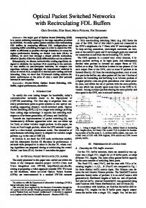
E. WDM labeling In a multiwavelength system, the labels of the packets in every wavelength channel may also be time-multiplexed in a separate common wavelength channel (see Fig. 6). This approach is, for instance, implemented in HORNET [7]. Thus, only the common wavelength channel needs to be inspected and processed for the label handling. However, careful synchronization of the individual label signals with the respective payload channels needs to be maintained, which requires time-slotted operation in all wavelength channels with careful synchronization among the channels. Chromatic dispersion in the fiber links may affect the strict synchronization, by introducing group velocity differences between the label-channel and the various payload channels; this requires tight dispersion control, and may become a serious issue at long link lengths and high payload rates. Furthermore, there is no close coupling between the labels and the data payloads, which implies comprehensive bookkeeping when routing in a larger scale node. Table I gives an overview of the various labeling techniques considered summarizing the observations made in this section. III. ORTHOGONAL LABELING TECHNIQUES As mentioned in Section II-A, orthogonal labeling has been pursued in the STOLAS project. The label information is orthogonally modulated in FSK format to the intensity-modulated data payload, as illustrated in Fig. 2. The payload data rate is usually much higher than the label rate, e.g., STOLAS used 10 Gbit/s versus 155 Mbit/s, respectively. The basic STOLAS node architecture is shown in Fig. 7(a). Inside the node, the packet bursts are routed by means of a passive wavelength router—arrayed waveguide grating router (AWGR)—that may be composed in a modular way by several smaller AWGRs. The FSK label information from each packet burst is read and after consulting a routing table the wavelength of the packet burst is changed accordingly in a tunable wavelength converter (TWC). The TWC is composed of a fast-tunable laser, which can be FSK modulated, and an MZI in which the IM payload drives the cross-phase modulation in the SOAs (see Fig. 8). As only the IM is transferred onto the new wavelength in such a wavelength converter, the FSK label is erased. Through FSK modulation of the tunable laser, a new label is attached. The node architecture of Fig. 7(a) may suffer from blocking: collisions may occur between packet bursts that are converted to the same wavelength in order to enter a common output fiber. In order to avoid these collisions, and thus, make the node
1544
IEEE JOURNAL OF SELECTED TOPICS IN QUANTUM ELECTRONICS, VOL. 13, NO. 5, SEPTEMBER/OCTOBER 2007
TABLE I COMPARISON OF PACKET LABELING TECHNIQUES
nonblocking, a second set of wavelength converters with fixed output wavelength (FWC) can be applied after the passive router, as shown in Fig. 7(b) [3]. By FSK modulating the CW output of the tunable pump laser in each of these FWCs, new labels can be affixed to the outgoing packet bursts. The passive router is composed of multiple AWGRs in a modular way, which enables scaling of the node to more input/output fibers and wavelength channels. A. Orthogonal Label-Controlled Packet Routing System Experiments 1) Impact of Extinction Ratio: As mentioned before, for adequate detection of the FSK label the extinction ratio (ER) of the IM payload should not be too high. On the other hand, a low ER causes a penalty for detection of the payload. Hence, the optimum ER is a compromise, depending on the payload data rate and the label data rate. Measurements have been done in the system setup shown in Fig. 9 [3]. The IM payload was a 10-Gbit/s PRBS 27 − 1 signal. Its FSK labeling was done at 50 Mbit/s with a tone spacing of 20 GHz allowing single-filter demodulation. Fig. 10(a) shows the receiver sensitivities for the IM payload and the FSK la-
bel, respectively, when the payload ER is increased from 6 to 12 dB. Due to the relatively low label data rate, the label receiver sensitivity is, then, only degraded by 2 dB, whereas the payload receiver sensitivity is improved by more than 3 dB. The optimum ER is found to be around 14 dB. At higher label rates, the degradation of the label receiver sensitivity is more pronounced because less payload bits per label bit are available. This yields a lower optimum ER [about 6.5 dB at 312 Mbit/s label rate as shown in Fig. 10(b)], and hence, a degraded IM payload receiver sensitivity [15]. The eye patterns for the 10-Gbit/s payload and the 312-Mbit/s label data are shown in Fig. 11. Next to lowering the label rate, applying forward error correction (FEC) coding on the label allows the increase of ER, and thus, improving the link budget. 2) Scalability: In order to assess the scalability of the labelswapping concept, experiments have been done by putting two label-swapping TWCs in cascade, using an ER of 7 and 12 dB [4]. Four wavelength channels were used, with a spacing of 200 GHz (1555.75, 1557.36, 1558.98, and 1560.61 nm). The payload bit error rate (BER) measurement results are shown in Fig. 12. Passing through a single TWC, a power penalty at BER = 10−9 is incurred of 2.7 dB for an ER = 7 dB, and of
KOONEN et al.: LABEL-CONTROLLED OPTICAL PACKET ROUTING—TECHNOLOGIES AND APPLICATIONS
1545
Fig. 10. Impact of payload extinction ratio at (a) 50-Mbit/s FSK label rate and (b) 312-Mbit/s FSK label rate.
Fig. 7. STOLAS label-controlled routing node. (a) Basic node architecture. (b) Nonblocking node architecture. Fig. 11. Detected eye pattern of (a) 10-Gbit/s payload and (b) 312-Mbit/s label, at the respective receivers.
Fig. 8. STOLAS tunable wavelength converter yielding FSK label swapping.
1.9 dB for ER = 12 dB. Passing two TWCs, the penalties are 5.3 and 4.4 dB, respectively. These cumulative penalties are largely due to insufficient speed of the SOAs inside the TWC, which causes patterning effects. With a payload rate of 10 Gbit/s and a dynamic range of 20 dB for the payload receiver, the insufficient TWC speed limits the cascadability to four nodes. At a lower payload speed of 2.5 Gbit/s, the penalties are found to be remarkably lower (< 2dB after passing six nodes); hence, much more nodes could be cascaded. B. Application of Orthogonal Labeling: Overspill Routing
Fig. 9. IM/FSK payload/label transmission testbed.
As an example of how the STOLAS orthogonal packet labeling could be deployed in a practical network on short term, the orthogonal labeling of overspill packets in a hybrid optical circuit switched/optical burst switched (OCS/OBS) network has been explored. This so-called ORION (overspill routing in optical networks) [16]—a network architecture developed within STOLAS—is exemplified in Fig. 13.
1546
IEEE JOURNAL OF SELECTED TOPICS IN QUANTUM ELECTRONICS, VOL. 13, NO. 5, SEPTEMBER/OCTOBER 2007
Fig. 12. Payload BER performance when cascading TWCs, for ER = 7 dB and ER = 12 dB.
Fig. 14. Time-serial label-swapping switch with two line ports (AOLSW: alloptical label swapper; demux: demultiplexer; mux: multiplexer; syn: synchronization; TWC: tunable wavelength converter).
Fig. 13. Labeled overspill routing.
Assume that 13-Gbit/s data packet traffic is to be sent from node A to B, whereas a single wavelength channel λ0 can only carry up to 10 Gbit/s. To realize this, one may route the excess 3 Gbit/s on a second wavelength channel λ1 from A to C, and then, via λ0 to B. This deflection routing solution uses quite some extra resources on the link B-C, and may fail when C already had to send, say 9 Gbit/s, to B. A more efficient solution is the ORION one, where the 3-Gbit/s excess packets are orthogonally labeled as being overspill packets, and are sent from A to B on λ1 . At B, by means of the label these packets are recognized as being overspill packets meant for B and are dropped at B, thus, avoiding additional load on the link B-C. System emulation experiments have shown that remarkable throughput gains can, thus, be reached [4]. ORION essentially is an add-on of packet-switching on top of a primarily circuit-switched network. This may be especially advantageous for traffic scenarios with a primarily stable aggregated traffic pattern, where capacity peaks may be accommodated by ORION packets. The ORION concept may, thus, be particularly attractive in the nearer term. IV. TIME-SERIAL LABELING WITH ALL-OPTICAL LABEL PROCESSING All-optical label processing for time-serial labels is pursued in the EU 6th Framework Programme project LASAGNE [5]. The switching node architecture is similar to the one in the STOLAS project: the packet switching is also done by tunable wavelength conversion and routing through an AWGR. The main difference lies in the label swapping process. Like STOLAS, the LASAGNE project addresses fixed-length opti-
Fig. 15. LASAGNE AOLSW label processing block diagram.
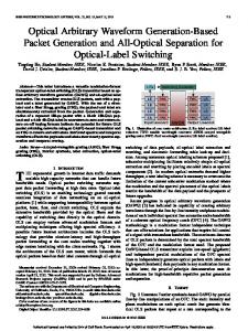
cal packets, but now with intensity-modulated optical time-serial labels in front of the payload, separated by a certain guard time. The LASAGNE switch uses all-optical EXCLUSIVE OR (XOR) correlators [17], [18] to compare the incoming label with the keyword indexes of the node forwarding table. These XORs generate a control pulse for the packet wavelength conversion, and thus, control the routing of the packet to the desired output port by an AWGR [19]. Fig. 14 shows a LASAGNE switch with two fiber input ports and two output ports; it is largely similar to the STOLAS one, including the fiber feedback loops facilitating buffering and multicasting as shown in Fig. 7. Inside the all-optical label switch (AOLSW) as illustrated in Fig. 15, the packet label is separated from the payload [20], and compared to a list of keywords, which are generated locally at each node according to the node forwarding table [21]–[23]. The keywords serve as the indexes of the node forwarding table. Each of the keywords maps a corresponding entry of the node forwarding table, where the new label pattern and the internal packet wavelength are indicated. When the old label matches one of the keywords, the relevant new label is generated and inserted, and the whole packet is then converted into the internal wavelength specified by the node forwarding table. The details of the AOLSW label processing logical interconnections are shown in Fig. 16. The label/payload separation circuit employs an all-optical AND logic gate in combination with a packet clock recovery circuit [24], which is required for
KOONEN et al.: LABEL-CONTROLLED OPTICAL PACKET ROUTING—TECHNOLOGIES AND APPLICATIONS
1547
Fig. 17. Qualitative cost comparison of electrical packet switching (EPS), OBS, and OCS. Fig. 16. LASAGNE AOLSW label processing logical connections.
the label extraction according to the TDM approach. In the label comparison subsystem, the label bits will be copied, and XOR correlated with locally generated optical keywords from the forwarding table, using SOA-MZI optical logic gates. Two label comparison schemes have been proposed: the first one is based on a feedback label correlation scheme [25], where the SOA-MZI compares the relevant bits of the time-serial label and the keyword, and if that particular bit matches, the generated optical pulse will be sent back through a feedback link to serve as the control pulse for the next bit correlation; the second one is based on cascaded label correlation scheme [17], [18], where still each SOA-MZI compares a pair of corresponding bits, and the resulting pulse of the previous bit match drives the next bit’s comparison by the next stage SOA-MZI. When there is an address match, which means all the bits of the label must match with the keyword, the relevant XOR gate produces an optical pulse, which sets the related optical flip-flop [26] in the control block. The optical flip-flops have two states of two different wavelengths. They are designed to change state when triggered by optical pulses, and in each state they emit one of the two wavelengths. In the AOLS packet switch, before receiving optical packets, the original state of these optical flip-flops is set to λ0 . After the label comparison, one of these optical flip-flops will change state and emit another wavelength. In the example shown in Figs. 15 and 16, the second flip-flop is triggered into its λ2 state. After a notch filter at λ0 , only this new wavelength will enter the wavelength converter as the continuous wave (CW) control signal for the wavelength conversion. Finally, the wavelength converter [27] converts the optical packet onto the assigned wavelength for the AWG routing toward the correct output port of the packet switch. This AOLSW core based on integrated SOA-MZIs has been demonstrated with all-optical routing of 40-Gbit/s nanosecondrange packets, allowing wavelength transparent operation and passive packet forwarding [19]. V. COMPARISON OF DATA ROUTING TECHNOLOGIES A. Cost Aspects As traffic volume increases, it becomes uneconomical and inefficient to use internet protocol (IP)/multiprotocol label switch-
ing (MPLS) electrical packet-per-packet processing and forwarding, since this limits the throughput, as well as requires relatively costly optoelectronic conversions at each node. Therefore, for end-to-end traffic volumes exceeding a certain value, OCS becomes more efficient than IP/MPLS. However, at 2.5, 10, and 40 Gbit/s per wavelength channel, OCS has a rather large granularity, so that the utilization of these circuits is often rather low. A detailed theoretical and network simulation study [28] has shown that the statistical multiplexing gains that can be obtained by optical packet switching (OPS) or OBS compared with OCS become significant only for highly bursty traffic of relatively large mean volume per source. Also, the larger the network, the larger are the gains obtained with OPS/OBS. In-depth studies have shown that an OPS/OBS network may typically require half the resources required by an OCS network in order to attain similar performance [28]. For sufficiently high end-to-end traffic volumes, OCS should theoretically become again more efficient than OPS/OBS. However, this cross-over point appears to lie beyond foreseeable practical levels, especially since traffic becomes more and more bursty with time at a higher pace than it increases in volume. These qualitative comparisons are depicted in Fig. 17. In addition to statistical multiplexing gains, OPS/OBS provides gains because of its lower granularity. These gains are manifested as a better flexibility to accommodate traffic variations, for e.g., due to daily fluctuation patterns or restoration processes, and as increased flexibility in implementing QoS and traffic engineering processes. These granularity related gains are manifested in particular when the traffic volume per end-to-end connection is small, i.e., of the order of a couple of channels while they decrease and become insignificant for a large count of channels per end-to-end connection. This combined with a thorough technoeconomic study [28] done in the STOLAS project suggests that IP/MPLS will either be displaced or transformed by optical technologies, and that in the longer term OPS/OBS will be introduced to combine the flexibility of packet technologies with the high throughput of optical switching technologies. B. Reliability Aspects The reliability of a packet routing node will largely depend on the cumulative failing probability of the active components; the passive components, once installed and connected properly, will not degrade noteworthily.
1548
IEEE JOURNAL OF SELECTED TOPICS IN QUANTUM ELECTRONICS, VOL. 13, NO. 5, SEPTEMBER/OCTOBER 2007
Furthermore, when a port-selecting gate fails in the B&S node, all wavelengths of that input port intended for a particular output fiber are blocked. Also, when a wavelength-selecting gate fails, all packets at that wavelength from every input port intended for a particular output fiber are blocked. In the STOLAS node, however, a failing TWC at the input side of the waveguide router blocks only a specific wavelength in a specific input fiber port. Such failures, therefore, affect less traffic in the STOLAS node than in the B&S node. VI. CONCLUSION Fig. 18. Basic B&S packet routing node.
In the STOLAS and LASAGNE node, the actual routing is done by the central passive arrayed waveguide router by means of allocating the appropriate wavelength to the packets. Typically, such a waveguide router is made by integrated-optics technology in a glass substrate, and hence, suffers no noteworthy degradation. Once connected and installed properly, this passive router itself should not cause failures. However, TWCs are needed at each side of the passive router, and these active elements may degrade. Such a TWC basically consists of a fast tunable laser diode and a wavelength converter based on SOAs in an MZI configuration. As an example, the nonblocking STOLAS node architecture given in Fig. 7(b) is considered. In this example, two input fiber ports, two output fiber ports, one add and one drop port are assumed. Two feedback loops are foreseen for multicasting. Each packet passes two TWCs and multiples of that when it is to be multicasted. So the probability that a packet is lost due to malfunctioning of the router is Pr[packet lost] = 1 − (1 − Pr[TWC failing])2 ≈ 2 Pr[TWC failing]. To compare this with alternative node designs, a broadcastand-select (B&S) node architecture has been considered. The B&S node equivalent with the basic STOLAS node is shown in Fig. 18, with again two input and output fiber ports, and one add and one drop port. Each packet now has to pass two fast optical gates, plus a TWC to adapt its wavelength. As such, the probability that a packet is lost due to malfunctioning of the router is Pr[packet lost] = 1 − (1 − Pr[gate failing])2 × (1 − Pr[TWC failing]) ≈ Pr[TWC failing] + 2 Pr[gate failing]. Comparing these two node designs, it can be observed that the B&S node requires more active components than the STOLAS node, and thus, it has a higher chance of malfunctioning somewhere in the node. Also the packet loss probability due to failures in the B&S node is higher than that in the STOLAS node, provided that Pr[gate failing] >
1 Pr[TWC failing]. 2
The throughput capacity of packet-routing nodes in an optical network can be significantly increased by keeping the payload data of the packets in the optical domain while controlling the routing by means of the packet labels. Thus, the optoelectronic-optical processing speed bottleneck for the payload data is avoided. Usually the label data rate is much lower than the payload data rate, and then, the label processing may be done in the electrical domain without compromising the node throughput. As shown in the STOLAS and LASAGNE projects, by using fast tunable lasers feeding wavelength converters and by using passive wavelength routing elements, a scalable modular router node with high reliability can be realized. Orthogonal labeling, pursued in STOLAS, is relatively easy to implement, and is robust against the timing constraints of the label with respect to the packet’s payload. It may first find applications in hybrid optical circuit/packet-switched networks. At very high payload data speeds using high-speed time-serial labels, all-optical label processing is required. The LASAGNE project has shown the feasibility of this concept by deploying advanced all-optical signal processing modules. ACKNOWLEDGMENT The authors would like to thank the other partners in the STOLAS and LASAGNE projects for their valuable contributions. REFERENCES [1] D. J. Blumenthal, B.-E. Olsson, G. Rossi, T. E. Dimmick, L. Rau, M. Masanovic, O. Lavrova, R. Doshi, O. Jerphagnon, J. E. Bowers, V. Kaman, L. A. Coldren, and J. Barton, “All-optical label swapping networks and technologies,” IEEE J. Lightw. Technol., vol. 18, no. 12, pp. 2058–2075, Dec. 2000. [2] A. M. J. Koonen, G. Morthier, J. G. L. Jennen, H. de Waardt, and P. Demeester, “Optical packet routing in IP-over-WDM networks deploying two-level optical labeling,” in Proc. ECOC, Amsterdam, the Netherlands, Sep. 30-Oct. 4, 2001, pp. 608–609. [3] A. M. J. Koonen, J. J. Vegas, Olmos, I. T. Monroy, J. G. L. Jennen, C. Peucheret, and E. van Breusegem, “Optical packet routing using orthogonal labelling-results from the FP5 STOLAS project,” presented at ECOC, Glasgow, U.K., Sep. 2005, Paper 4.4.1. [4] I. T. Monroy, E. V. Breusegem, T. Koonen, J. J. Vegas Olmos, J. van Berkel, J. Jennen, C. Peucheret, and E. Zouganeli, “Optical label switched networks: laboratory trial and netwok emulator in the IST-STOLAS project,” IEEE Commun. Mag., vol. 44, no. 8, pp. 43–51, Aug. 2006. [5] F. Ramos, E. Kehayas, J. M. Martinez, R. Clavero, J. Marti, L. Stampoulidis, D. Tsiokos, H. Avramopoulos, J. Zhang, P. V. HolmNielsen, N. Chi, P. Jeppesen, N. Yan, I. T. Monroy, A. M. J. Koonen, M. T. Hill, Y. Liu, H. J. S. Dorren, R. V. Caenegem, D. Colle, M. Pickavet, and B. Riposati, “IST-LASAGNE: Towards all-optical label swapping
KOONEN et al.: LABEL-CONTROLLED OPTICAL PACKET ROUTING—TECHNOLOGIES AND APPLICATIONS
[6] [7] [8] [9]
[10]
[11]
[12]
[13]
[14]
[15]
[16]
[17] [18] [19]
[20]
[21]
[22] [23] [24] [25]
employing optical logic gates and optical flip-flops,” IEEE J. Lightw. Technol., vol. 23, no. 10, pp. 2993–3011, Oct. 2005. J. P. A. van Berkel, J. J. Vegas Olmos, I. T. Monroy, and A. M. J. Koonen, “Influence of non-optimal filtering on FSK/IM modulaetd signals,” presented at ECOC, Glasgow, U.K., Sep. 2005, Paper 3.4.5. I. White, M. Rogge, Y.-L. Hsueh, K. Shrikhande, and L. Kazovsky, “Experimental demonstration of the HORNET survivable bi-directional ring architecture,” presented at OFC, Anaheim, CA, Mar. 2002, Paper WW1. Y. M. Lin, W. I. Way, and G. K. Chang, “A novel optical label swapping technique using erasable optical single-sideband subcarrier label,” IEEE Photon. Technol. Lett., vol. 12, no. 8, pp. 1088–1090, Aug. 2000. B. Meagher, G. K. Chang, G. Ellinas, Y. M. Lin, W. Xin, T. F. Chen, X. Yang, A. Chowdhury, J. Young, S. J. Yoo, C. Lee, M. Z. Iqbal, T. Robe, H. Dai, Y. J. Chen, and W. I. Way, “Design and implementation of ultralow latency optical label switching for packet-switched WDM networks,” IEEE J. Lightw. Technol., vol. 18, no. 12, pp. 1978–1987, Dec. 2000. H. J. Lee, V. Hernandez, V. K. Tsui, and S. J. B. Yoo, “Simple, polarization-independent, and dispersion-insensitive SCM signal extraction technique for optical switching systems applications,” Electron. Lett., vol. 37, no. 20, pp. 1240–0000, 2001. G. Cincotti, N. Wada, and K.-I. Kitayama, “Characterization of a full encoder/decoder in the AWG configuration for code-based photonic routers—Part I: Modeling and design,” IEEE J. Lightw. Technol., vol. 24, no. 1, pp. 103–112, Jan. 2006. N. Wada, G. Cincotti, S. Yoshima, N. Kataoka, and K.-I. Kitayama, “Characterization of a full encoder/decoder in the AWG configuration for codebased photonic routers—Part II: Experiments and applications,” IEEE J. Lightw. Technol., vol. 24, no. 1, pp. 113–121, Jan. 2006. Y. G. Wen, Y. Zhang, and L. K. Chen, “On architecture and limitations of optical multiprotocol label switching (MPLS) networks using opticalorthogonal-code (OCC)/wavelength label,” Opt. Fiber Technol., vol. 8, pp. 43–70, 2002. H. Sotobayashi, W. Chujo, and K.-I. Kitayama, “Photonic gateway: Multiplexing format conversions of OCDM-to-WDM and WDM-to-OCDM at 40 Gbit/s (4 × 10 Gbit/s),” IEEE J. Lightw. Technol., vol. 20, no. 12, pp. 2022–2028, Dec. 2002. J. Zhang, N. Chi, P. V. Holm-Nielsen, C. Peucheret, and P. Jeppesen, “An optical FSK transmitter based on an integrated DFB laser/EA modulator and its application in optical labeling,” IEEE Photon. Technol. Lett., vol. 15, no. 7, pp. 984–986, Jul. 2003. E. Van Breusegem, J. Cheyns, D. Colle, M. Pickavet, and P. Demeester, “Overspill routing in optical networks: A new architecture for future-proof IP over WDM networks,” Proc. SPIE, vol. 5285, no. 13, pp. 226–236, 2003. J. M. Martinez, J. Herrera, F. Ramos, and J. Mart´ı, “All-optical correlation using cascaded logic XOR gates based on active Mach–Zehnder interferometers,” in Proc. ECOC, Glasgow, U.K., Sep. 25–29, 2005, pp. 103–104. J. M. Martinez, F. Ramos, and J. Marti, “All-optical packet header processor based on cascaded SOA-MZIs,” Electron. Lett., vol. 40, no. 14, pp. 894–895, Jul. 2004. J. Seoane, P. V. Holm-Nielsen, P. Jeppesen, E. Kehayas, H. Avramopoulos, Y. Liu, S. Zhang, H. J. S. Dorren, J. M. Martinez, J. Herrera, F. Ramos, J. Mart´ı, R. McDougall, and G. D. Maxwell, “Towards transparent alloptical label-swapped networks: 40 Gb/s ultra-fast dynamic wavelength routing using integrated devices,” presented at ECOC, Cannes, France, Sep. 24–28, 2006, Paper We2.4.5. O. Zouraraki, D. Petrantonakis, D. Apostolopoulos, E. Kehayas, N. Pieros, and H. Avramopoulos, “A 40 Gbps all-optical label/payload separation circuit using hybrid integrated MZI switches,” presented at ECOC, Cannes, France, Sep. 24–28, 2006, Paper Th1.4.1. D. C. Rogers, J. V. Collins, C. W. Ford, J. Lucek, M. Shabeer, and G. Sherlock et al., “Optical pulse pattern generation for self-synchronizing 100 Gbit/s networks,” in Proc. OFC Tech. Dig., Feb./Mar. 1996, pp. 98– 99. T. Otsuji, M. Yaita, T. Nagatsuma, and E. Sano, “10-80-Gb/s highly extinctive electrooptic pulse pattern generation,” IEEE J. Select. Top. Quantum. Electron., vol. 2, no. 3, pp. 643–649, Sep. 1996. K. L. Hall and K. A. Rauschenbach, “All-optical bit pattern generation and matching,” Electron. Lett., vol. 32, no. 13, pp. 1214–1215, Jun. 1996. L. Stampoulidis, E. Kehayas, H. Avramopoulos, Y. Liu, E. Tangdiongga, and H. J. S. Dorren, “40 Gb/s fast-locking all-optical packet clock recovery,” in Proc. OFC Tech. Dig., Anaheim, CA, Mar. 2005, pp. 199–201. J. M. Martinez, F. Ramos, J. Marti, J. Herrera, and R. Llorente, “All optical N-bit XOR gate with feedback for optical packet header processing,” presented at ECOC, 2002, Paper P4.8.
1549
[26] R. McDougall, G. Maxwell, R. Harmon, L. Rivers, A. Poustie, Y. Liu, M. T. Hill, S. Zhang, F. Huijskens, and H. J. S. Dorren, “Hybrid-integrated, alloptical flip-flop memory element for optical packet networks,” presented at ECOC, Cannes, France, Sep. 24–28, 2006, Paper Th1.4.5. [27] M. L. Nielsen, M. Nord, M. N. Petersen, B. Dagens, A. Labrousse, R. Brenot, B. Martin, S. Squedin, and M. Renaud, “40 Gbit/s standardmode wavelength conversion in all-active MZI with very fast response,” Electron. Lett., vol. 39, no. 4, pp. 385–386, 2003. [28] E. Zouganeli, R. Ø. Andreassen, B. Feng, N. Stol, A. Solem, B. E. Helvik, A. Sudbø, and R. B. Haugen, “Optical packets, circuits, or packets and circuits: Viability of optical packet/burst switching,” presented at OECC, Seoul, Korea, Jul. 4–8, 2005, Paper 6A2-1.
A. M. J. Koonen (M’00–SM’01–F’07) received the M.Sc. (cum laude) degree in electrical engineering from Eindhoven University of Technology, Eindhoven, The Netherlands, in 1979. He was with Bell Laboratories in Lucent Technologies as a Technical Manager of applied research for more than 20 years. He was a part-time Professor at Twente University, Enschede, The Netherlands from 1991 to 2000. Since 2001, he is a Full Professor at Eindhoven University of Technology in the Electrooptical Communication Systems Group at COBRA Institute, where he is the Chairman of this group since 2004. His current interests include broadband fiber access networks and optical packet-switched networks. He has initiated and led several European and national R&D projects in this area on label-controlled optical packet routed networks, dynamically reconfigurable hybrid fiber access networks, fiber-wireless, packet-switched access, and short-range multimode (polymer) optical fiber networks. Currently, he is involved in a number of access/in-home projects in the Dutch Freeband programme, the Dutch IOP Generieke Communicatie programme, and the EC FP6 IST Broadband for All programme. Prof. Koonen is a Fellow of Bell Laboratories since 1998.
Ni Yan was born in Hubei, China, in January 1979. She received the B.Eng./B.Sc. (honors) degree in communication engineering from Zhongshan University (ZSU), Guangzhou, China, and the M.Sc. (with distinction) degree in telecommunications (for industry) from the University College London (UCL), London, in June 2001 and September 2003, respectively. Currently, she is working toward the Ph.D. degree at the Electrooptical Communication Systems Group, COBRA Institute, Eindhoven University of Technology, Eindhoven, The Netherlands. Earlier, she was involved in the European Commission funded projects IST-LASAGNE and IST-STOLAS. Her current research interests include optical data communication systems, optical label-switched node architectures, all-optical wavelength conversions, packet router technologies, and computer networks and their applications.
J. J. Vegas Olmos was born in Barcelona, Spain, in 1978. He received the B.Sc. degree in telecommunications engineering and the M.Sc. degree in electronic engineering from the Universitat Politecnica de Catalunya, Barcelona, Spain, in 2001 and 2003, respectively, the Licenciature degree in business administration from the Universitat Oberta de Catalunya, Catalonia, Spain, in 2005, and the Ph.D. degree from Eindhoven University of Technology, Eindhoven, The Netherlands, in 2006. Currently, he is a Research Fellow at Osaka University, Osaka, Japan. He participated in the European research projects ISTLASAGNE and IST-STOLAS. Dr. Vegas Olmos was awarded with the IEEE Lasers and Electro-Optics Society Graduate Student Fellowship in 2006.
1550
IEEE JOURNAL OF SELECTED TOPICS IN QUANTUM ELECTRONICS, VOL. 13, NO. 5, SEPTEMBER/OCTOBER 2007
Idelfonso Tafur Monroy received the graduate and the M.Sc. degree in multichannel telecommunications from the Bonch-Bruevitch Institute of Communications, St. Petersburg, Russia, in 1992, the Technology Licenciate degree in telecommunications theory from the Royal Institute of Technology, Stockholm, Sweden, in 1996, and the Ph.D. degree from Eindhoven University of Technology, Eindhoven, The Netherlands in 1999. He was an Assistant Professor with the Electrooptical Communication Systems Group of Eindhoven University of Technology, till 2006. Currently he is an Associate Professor in the Department of Communications, Optics and Materials (COM·DTU) at the Technical University of Denmark (DTU), Copenhagen, Denmark. He has participated in several European research projects such as APEX, STOLAS, LASAGNE, and MUFINS. His research interests include optical label and packet switching, nanophotonic technologies and systems for integrated metro and access networks, and communication theory.
Christophe Peucheret received the engineering degree from Ecole Nationale Sup´erieure des T´el´ecommunications de Bretagne, Brest, France, in 1994, the M.Sc. degree in microwaves and optoelectronics from the University College London, London, in 1994, and the Ph.D. degree from the Technical University of Denmark (DTU), Copenhagen, Denmark, in 2003. He is currently an Associate Professor in the Department of Communications, Optics and Materials (COM•DTU) at DTU, working in the field of modulation formats for transmission and optical networking. He has been coordinating COM·DTU’s activities in the STOLAS project.
Erik Van Breusegem received the M.Sc. and Ph.D. degrees from Ghent University, Ghent, Belgium, in 2001 and 2006, respectively. He was a Researcher in the Department of Information Technology (INTEC), Ghent University, as part of the research group INTEC Broadband Communication Networks. His research interests include optical networks in general, with a focus on hybrid optical network designs. He was involved in several IST projects such as STOLAS, NOBEL, and LASAGNE, and in COST-Action 266. He is the author of over 40 scientific publications in international journals and conference proceedings.
Evi Zouganeli received the B.Sc. degree in applied physics from the University of Patras, Patras, Greece, in 1985, the M.Sc. degree in telecommunications and the Ph.D. degree in optoelectronics from the University College London, London, in 1988 and 1992, respectively, and the Master of Management degree from the Norwegian School of Management, Oslo, Norway, in 2001. She was a Postdoctoral Researcher at the Swiss Federal Institute of Technology, Zurich, Switzerland. In 1994, she joined Telenor R&D, Norway, where she is currently a Senior Research Scientist focussing on high-capacity optical networks, broadband access, network migration and upgrading strategies, and technology evaluations.