Landmark Selection for Task-Oriented Navigation - CS Technion
Recommend Documents
nion—Israel Institute of Technology, Haifa 32000, Israel (e-mail: ronenl@cs. technion.ac.il; [email protected]). I. Shimshoni is with the Department of ...
Search engines, multifaceted search, facet selection ... The algorithm selects facets that optimize the rank promo- ... the optimization problem of facet selection.
stored as 16x16 templates with a magni cation factor of. 5). Landmarks in Image Sectors. Bianco et al 1999] divides the visual eld up into a num- ber of sectors.
ence, University of Toronto, Toronto, ON M5S 3G4, Canada (e-mail: [email protected] ... R. Sim is with the Department of Computer Science, University of British. Columbia ..... from-motion problem online [25] using the Shi and Tomasi fea-.
Given a match to some land- .... isting vision methods to visual information acquisition, land- ..... tains the -coverable poses which are still unassigned to some.
Near-optimal Landmark Selection for Mobile Robot Navigation. Maximilian Beinhofer. Jörg Müller. Wolfram Burgard. AbstractâThe ability to accurately localize ...
trieve relevant documents that do not mention query terms explicitly, in particular when ..... query and filtering track experiments using pircs. In TREC, 217â. 228.
a vision-based localization sensor with active naviga- tion. We explain the localization process, how its per- formance varies across the configuration space, and ...
image planes are parallel to each other and the epipoles ... its corresponding point (x', y', f)T E I', ... their corresponding points in the current image, namely.
Jun 4, 2006 - Eldad Silberstein5, Yael Feferman1 & Ohad S Birk1,7. We describe an Israeli Jewish ..... Cohen-Sfady, M. et al. J. Immunol. 175, 3594â3602 ...
Both functional verification and program equivalence of general programs are ... for software â and equivalence checking â the most popular formal verification ...
has some scala b ility limitations, and is not as porta b le or interopera b le as, e .g ., the use of ..... I n Proc. of the TINA 96 Conference , pages 2 5-41 , September.
Aug 6, 2014 - level and then plays a three-second sound at each fre- quency ..... raw data by building in complex wear-leveling logic. There are some works ...
BIOGRAPHY. Quentin Ladetto is a Ph.D. candidate in the Geodetic. Engineering Laboratory at the Swiss Federal Institute of. Technology in Lausanne (EPFL).
OSCAR H. IBARRA* AND SHLOMO MORAN*, f. Department of Computer Science, University of Minnesota, Minneapolis, Minnesota. AND. ROGER Huit.
May 22, 2000 - Direct access, i.e., hash tables, ... hash tables are not the ... they lead to unbalanced structures: i.e., accessing some data might require passing.
section 6, we discuss a control hierarchy adopted in the AV-shell .... Asynchronous Recurrent Composition: T = P(v) .... to the set of attentive routines found in the AVIL. The AVIL ... example is to have the head track the train and signal when the
lorca, Spain. Received January 4, 1996 / Revised version received August 2, 1996. Summary. A novel geometric approach for three dimensional object ...
For example, if we have a pattern "White Rook at (1) attacks Black Pawn at (2) defended by Black Pawn at (3)" (the rever
Some people attribute such capability to ... approach to solve this problem is to pre-program the agent with a domain-sp
articulated objects, and make them play on stages from a computer graphics .... software, such as the 3D Studio Max, and then can be loaded to the application .... Furthermore, when using iterative methods, we can stop the solution process.
Jun 21, 2010 - the x86-64 architecture, some legacy I/O devices do not support long addresses and therefore cannot access the entire physical memory [7].
is searching for the maximum (resp. minimum) price of some asset. At each ..... Although randomization cannot help in one-way trading we will see that ... fixed transaction costs are introduced the deterministic competitive ratio increases and.
thus, practically speaking, useless when a large number of participants are involved. The contribution of this paper is to define a new privacy model â k-privacy ...
Landmark Selection for Task-Oriented Navigation - CS Technion
AbstractâMany vision-based navigation systems are restricted to the use of only a ... algorithm is proposed for subset selection from the available land- marks.
494
IEEE TRANSACTIONS ON ROBOTICS, VOL. 23, NO. 3, JUNE 2007
Landmark Selection for Task-Oriented Navigation Ronen Lerner, Ehud Rivlin, Member, IEEE, and Ilan Shimshoni, Member, IEEE
Abstract—Many vision-based navigation systems are restricted to the use of only a limited number of landmarks when computing the camera pose. This limitation is due to the overhead of detecting and tracking these landmarks along the image sequence. A new algorithm is proposed for subset selection from the available landmarks. This algorithm searches for the subset that yields minimal uncertainty for the obtained pose parameters. Navigation tasks have different types of goals: moving along a path, photographing an object for a long period of time, etc. The significance of the various pose parameters differs for different navigation tasks. Therefore, a requirements matrix is constructed from a supplied severity function, which defines the relative importance of each parameter. This knowledge can then be used to search for the subset that minimizes the uncertainty of the important parameters, possibly at the cost of greater uncertainty in others. It is shown that the task-oriented landmark selection problem can be defined as an integer-programming problem for which a very good approximation can be obtained. The problem is then translated into a semi-definite programming representation which can be rapidly solved. The feasibility and performance of the proposed algorithm is studied through simulations and lab experimentation. Index Terms—Covariance matrix, feature selection, landmarks, pose estimation, semi-definite programming (SDP).
I. INTRODUCTION N THIS PAPER, the problem of landmark-based navigation is examined. Landmarks are distinctive features in the surrounding scene for which the 3-D location is known with respect to some global coordinate system. Consider an autonomous vehicle equipped with a camera. In order to perform vision-based navigation, a set of predefined landmarks is supplied and the 2-D projections on the camera’s image-plane are identified and tracked during the vehicle’s movement. Given the 3-D and 2-D data, the navigation problem is defined as the estimation of the camera pose (position and orientation) with respect to the global reference frame. During the last two decades robust pose estimation algorithms have been developed by the computer vision community. These algorithms can integrate an arbitrary number of landmarks in the pose computation, leading to accurate and numerically stable results (e.g., [1]–[6]). However, due to performance limitations, many real-time navigation systems are restricted to the use of only a very small number (usually 4–10) of landmarks. This limitation arises from the large overhead of detecting and tracking
I
Manuscript received March 20, 2006; revised October 31, 2006. R. Lerner and E. Rivlin are with the Department of Computer Science, Technion—Israel Institute of Technology, Haifa 32000, Israel (e-mail: ronenl@cs. technion.ac.il; [email protected]). I. Shimshoni is with the Department of Management Information Systems, University of Haifa, Haifa 31905, Israel (e-mail: [email protected]). This paper contains supplementary multimedia material available at http://ieeexplore.ieee.org, provided by the author. This material consists of some videos in avi format, showing the experiments discussed in this paper. This material is 15.4 MB in size. Digital Object Identifier 10.1109/TRO.2007.895070
these landmarks along the image sequence. In [7], for example, a navigation system is presented where only four landmarks are simultaneously tracked. If the number of available landmarks is small as well, the system will use all the visible landmarks at hand. However, if the system is equipped with a large landmark database, a subset needs to be selected from the visible landmarks as the camera moves. An example of such a scenario is an unmanned aerial vehicle (UAV) that utilizes a digital map and an ortho-photo of the observed terrain. In this configuration, the 3-D location of any point on the terrain is known, and any visually distinctive point can thus be used as a landmark. The number of potential landmarks in such a case is large, and a subset must be chosen. Another example is a simultaneous localization and map building (SLAMB) system such as the ones in [8]–[11]. These systems estimate the camera motion and simultaneously track new features along the path of the robot’s movement. The 3-D locations of the tracked features are reconstructed and added to a landmark database. As a result, the database is progressively enlarged and after a while there will be more visible landmarks than it is possible to track. While the navigating platform moves, new landmark subsets should be occasionally selected. The need for a new subset may arise, for example, when one of the landmarks leaves the camera field of view or after the camera has moved more than a certain distance since the last subset was chosen. Whenever a new subset is required, an initial guess of the camera pose can be utilized to filter the landmarks which are supposed to be visible at the moment and to predict their projection location on the image before actually detecting them. At this stage we face an important question: how do we choose the subset from the filtered landmarks wisely, in a manner that will lead to the best pose estimate according to the requirements of the specific navigation task? This task-oriented landmark selection problem stands at the center of the present work. In most previous works (e.g., [8], [12], and [13]), the landmark selection problem was addressed from the image appearance standpoint, where the 3-D location of the landmarks was disregarded and the selection criterion based solely on a measure of distinction of the 2-D features in the captured image. In [14], the region from which each landmark is visible constituted the selection criteria in order to construct a small landmark subset that can be used from a variety of locations. In [7], [15], and [16], as in the present work, the 3-D structure of the selected landmark constellation and its influence on the obtained accuracies was studied. In [15], the design of special positioning objects (i.e., fiducials) was considered. The relatively small dimensions of such objects (compared to their distance from the imaging device) enabled the authors to assume weak-perspective projection, which is inadequate for general landmark-based navigation. In [7] and [16], a full-perspective projection model was used; however, the navigation problem
LERNER et al.: LANDMARK SELECTION FOR TASK-ORIENTED NAVIGATION
was restricted to a two-dimensional world where only three pose parameters had to be estimated. None of the aforementioned works addressed task-oriented considerations when selecting the landmark subset. Both [7] and [15] used the condition number of the pose covariance matrix as the landmark selection criterion. This criterion does not reflect the different severity of errors in the different pose parameters. For example, a unit error in the camera’s position (e.g., 1 cm) should not be considered equivalent to an angular unit error (e.g., 1 rad) in its orientation. Additionally, the purpose of the pose computation should not be overlooked. The navigation system usually supports a control system that uses the pose estimates to perform some predefined task. According to the requirements of the specific task, some of the pose parameters may be considered more essential than others. For example, if the platform needs to follow a predefined path, then accurately identifying its location along the path is not as important as identifying any drifts from the path. Another example is the task of landing an airplane on a landing track. Obviously, the set of relevant parameters and accuracies during landing differs from those that need to be controlled for maintaining straight and level flight. It would thus be desirable to select a subset of landmarks that minimizes the error in some of the pose parameters even at the expense of larger errors in the other parameters. In this paper we present a new criterion for task-oriented landmark selection. The system designer can use a severity function to specify the adequacy of different poses for the specific navigation task. This function can be used to construct a requirements matrix that reflects the importance of the different pose parameters for the task at hand. Next, we show that the landmark subset selection problem can be approximated by solving a semi-definite programming (SDP) problem. A solution for this class of optimizations can be found easily and rapidly, qualifying the proposed algorithm for real-time navigation systems. Although this paper shows how SDP can be utilized for landmark selection, it can also be applied to variety of problems from the computer-vision and robotics fields. The paper continues as follows. Section II reviews the topic of pose estimation from landmarks and its uncertainty. A method for evaluating how well the different subsets conform to the requirements of the navigation task is developed in Section III. A good and efficient approximate solution to the subset selection problem is presented in Section IV. Section V presents a method for translating the preferences of the navigation task into a requirements matrix. Experimental results on simulated and real data are presented in Section VI. We conclude in Section VII. II. LANDMARK-BASED NAVIGATION Before considering the task-oriented landmark selection problem, we briefly summarize the landmark-based navigation be a set of available problem. Let landmarks. The 3-D location of these points is assumed to be known with respect to some reference coordinate system . In order for an autonomous vehicle to navigate in this scene, it is equipped with a calibrated camera, to which another Cartesian coordinate system, denoted , is attached. Traditionally, the origin of this system coincides with the camera’s center of projection and the axis is oriented along the optical axis. The
495
pose of the camera with respect to orthonormal rotation matrix, such that position vector
can be represented by an , and by the camera
(1) where is the representation of in the camera’s system . Due to the orthonormality of , the camera’s orientation has only three degrees of freedom, usually represented by the and , which reflect the rotation around the Euler-angles and axes, respectively. Thus, the camera pose is fully . defined by a 6-D parameter vector, In the camera frame, the 3-D landmarks are perspectively projected to their 2-D location in the image-plane (2) Given the 3-D landmarks and their corresponding 2-D camera , the navigation problem is to accurately measurements estimate the camera pose parameters - . These parameters can be estimated by a nonlinear optimization procedure that minimizes the squared error between the camera’s 2-D measurements and the landmark projections (which are calculated using the pose hypothesis) (3) This least-squares solution is known to be the optimal solution when independently and identically distributed (i.i.d) isotropic errors are assumed. However, this solution is also known to be extremely sensitive to outliers. In order to estimate the pose parameters in a more robust manner, standard robust techniques, such as M-estimation (that searches for a reweighted least-squares solution), should be used in practice. In the present work it is assumed that the pose parameters are periodically estimated as part of the control-loop. As a result, a relatively accurate initial guess of these parameters is always available. Hence, any outlier will yield a large residual from the very beginning and therefore it will be easily suppressed using the aforementioned robust techniques. A. Pose Covariance Matrix The 2-D measurements obtained from the camera are not error-free. These errors result from errors in the feature detection procedure and are commonly modelled as i.i.d Gaussian additive errors. Let be the standard deviation of this isotropic Gaussian distribution. In the absence of these errors the exact would have been obtained; however, in realistic scepose narios these errors propagate through the optimization process and lead to the perturbed estimate of the pose . be the perspective projection function of the Let th landmark (4) Then the Jacobian of the ith landmark is the 2 6 matrix containing all ’s partial derivatives, and the Jacobian matrix
496
IEEE TRANSACTIONS ON ROBOTICS, VOL. 23, NO. 3, JUNE 2007
of all the landmarks which participate in the pose computation is defined as the concatenation of all the respective ’s (5) Following the derivations in [17], a first-order approximation of the error propagation from image measurements to the pose parameters is given by the covariance matrix of (6) in the above expression is the covariance matrix of the where image measurements, which reflects the errors in the 2-D measurements. Since it was assumed that these errors are i.i.d. and takes the special form of a diagonal matrix with isotropic, along the diagonal. Hence, the expression for constant value the pose covariance matrix may be simplified as follows:
(7) The diagonal of the pose covariance matrix contains the variances of the six pose parameters, while the off-diagonal elements represent the dependencies between these parameters. This symmetric matrix also represents a 6-D ellipsoid (usually known as the uncertainty ellipsoid) in the pose configuration space. The main axes of this ellipsoid are in the direction of ’s eigenvectors and their lengths correspond to the square’s eigenvalues. One can think of this ellipsoid as an roots of approximation of the volume in which the real pose is located up to some certainty. For accurate pose estimates this volume will be relatively small. III. TASK-ORIENTED GRADING OF LANDMARK SUBSETS Consider a scenario where 100 landmarks are available for robot navigation. Selecting all these landmarks for the camera pose computation will probably yield a very accurate estimate. However, for each selected landmark, its 2-D measurements need to be extracted from each image along the robot’s trajectory. A feature-extraction algorithm may be used in the first frame in order to identify the landmarks in the image, and some tracking algorithm will be used in the consecutive frames to obtain the 2-D feature displacement. Since navigation is a realtime task, the overhead of the tracking procedure must be considered. According to the specific system capabilities and performance, the maximal number of features that can be tracked is usually bounded to be very small (e.g., 10 or even 4, as was proposed in [7]). It is clear that different selections of landmark subsets will lead to different pose accuracies. As an illustrative example, consider the choice of a subset containing landmarks with very small distances between them. Their projection rays will form a very narrow bundle, which will in turn lead to a very inaccurate pose estimate as compared to a subset of landmarks that are far away from each other. The landmark selection problem is simply defined as the problem of finding the best subset—the one that will lead to the most accurate pose.
Fig. 1. Comparison between uncertainty ellipsoids in a 3-D pose configuration space. It is clear that ellipsoids B and C are preferable to A, but the choice between these two is less obvious and should take into account the requirements of the specific navigation task.
As was already shown in Section II-A, the pose accuracy is not represented by a scalar but rather by a 6 6 covariance matrix. Any landmark subset will lead to a different covariance matrix. This leads to a fundamental question: given two covariance matrices, which one is “better” ? Each covariance matrix reflects an uncertainty ellipsoid. If one of the ellipsoids contains the other, then it is clear that the smaller one should be preferred. For example, one can see that ellipsoids B and C in Fig. 1 are preferable to ellipsoid A. However, the choice between ellipsoids B and C is less obvious and should take into account the requirements of the specific navigation task. For example, if for some reason the -parameter is much more important than the -parameter to our navigation task, it may be preferable to choose ellipsoid C over ellipsoid B although it has higher uncertainty along the (less important) -direction. In [7] and [15], each landmark subset was graded according to the condition number of its covariance matrix, which is defined as the ratio between the largest and smallest eigenvalues. In terms of uncertainty ellipsoids, the condition number is the squared lengths ratio of the longest and shortest main-axes, thus measuring the “roundness” of the ellipsoid. Using this criterion will bring us to choose the landmark subset with the most spherical uncertainty ellipsoid. Note that in our 3-D example, ellipsoid A would have been chosen according to the condition number. Another problem with this criterion is that it perceives the configuration space as a Euclidian space, and thus an error of one angular unit (e.g., radian) in the camera orientation would be considered equivalent to an error of one metric unit (e.g., centimeter) in the pose translation vector. This behavior seems arbitrary and does not reflect the real severity of such errors. In order to address the aforementioned issues, a new grading criterion for landmark subsets is proposed. First, instead of grading according to the uncertainty ellipsoid’s roundness, we would like to use a criterion that reflects its size. Two straightforward alternatives are the summation and the product of the covariance matrix eigenvalues. These quantities can be easily obtained as the covariance matrix’s trace and determinant, respectively. At first glance, it seems that the product of the eigenvalues would be a better choice since it is proportional to the squared volume of the uncertainty ellipsoid. However, such a criterion might prefer an ellipsoid with a very long axis when the rest of the axes are very short and hence compensate for the long one. When summing the eigenvalues, on the other hand, the squared lengths of the axes are summed and hence will be relatively large even if only one of the axes is long.
LERNER et al.: LANDMARK SELECTION FOR TASK-ORIENTED NAVIGATION
Additionally, a requirements matrix should be supplied by the system designer, who is familiar with the requirements of the , specific navigation task. The requirements matrix, denoted should be symmetric, positive semi-definite, and reflect the importance of the different pose parameters (particularly the correct balance between angular and translational errors). The length of the uncertainty ellipsoid’s main axes will not be measured using the Euclidian norm but rather by the Mahalanobis norm induced by this requirements matrix. In Section V a systematic method for constructing such a matrix is described. that was obtained from a Given a covariance matrix landmark subset, the grading criterion is developed as follows. be the eigenvectors-eigenvalues deLet . is an orthonormal composition of matrix in which the eigenvectors of the covariance matrix is a diagonal matrix containing the are its columns, and eigenvalues- . Therefore, the grade of the covariance matrix, which is defined to be the sum of squared Mahalanobis lengths of the ellipsoid’s main axes, is grade
497
To conclude, given the requirements matrix of the navigation task, any landmark subset can be evaluated in a task-oriented manner by computing its corresponding covariance matrix, and then grading it according to the trace of the multiplication of these two matrices. IV. APPROXIMATE SOLUTION FOR THE SUBSET SELECTION PROBLEM Equipped with the task-oriented grading criterion, we can address the central problem of this work: the task-oriented landmark selection problem. Given a set of available and visible landmarks, we would like to obtain the best landmark subset of . This problem can be posed as some predefined size an integer programming optimization problem by introducing indicator variables, , each indicating whether the corresponding landmark was selected to the subset. be the vector concatenation of these variLet in (7) according ables. Stipulating the participation of each to its corresponding yields the subset’s covariance matrix (10) By substituting (10) into (9) and ignoring the constant factor , the integer-program becomes
(8) where denotes the Mahalanobis norm. In contrast to a ’s eigenvalues, here we obtained their simple summation of represent the severity of weighted sum. The weights the pose errors in the direction. During the optimization process, where the landmark subset with the minimal grade is sought, the grade function is evaluated many times for different subsets. Therefore, in order to reduce the overhead of the optimization, it would be desirable to avoid . Since it is the eigenvectors-eigenvalues decomposition of only the sum of squared lengths that we need for the grade computation, this function takes a much simpler form grade
(9)
where represents the matrix trace. The two grade definitions (8) and (9) are equivalent since
where is the diagonal matrix containing the square roots . In the above manipulation we used of the six eigenvalues— a cyclic permutation of the matrices in the trace. Such a permutation is known to preserve the trace.
(11) The first constraint guarantees that the obtained subset size will be as required, while the second constraint enforces the Boolean behavior of the indicators. Computing the exact solution for this program is NP-Hard. However, a very good approximation can be obtained by solving the problem relaxation, where the Boolean restriction of the variables is replaced by the relaxed constraint . The objective function of this program is convex (see Appendix I) and can be solved using any nonlinear optimization toolbox (e.g., [18]) to obtain the fractional solution. In order to decide which of the landmarks should be selected, a rounding variheuristic should be applied to the obtained fractional ables. A well-known rounding method [19] proceeds as follows: each fractional is perceived as the probability that the corresponding landmark will be selected to the subset. Hence, several subsets are randomly constructed according to these probabilities; next, the grade of each subset is evaluated according to (9), and the subset with the minimal grade is chosen. Note that although the expected size of the subsets is as desired (due to the subset size constraint), the actual size of the randomly generated subsets may be slightly different. Therefore, the random subsets should be corrected by adding or discarding landmarks in order to reach the necessary size, where the choice of which landmarks to add/discard is in accordance with the value of each
498
IEEE TRANSACTIONS ON ROBOTICS, VOL. 23, NO. 3, JUNE 2007
fractional : for subsets that are too large we will discard the landmarks with the lowest , and for subsets that are too small we will add the landmarks with the largest . Experimental results, which are presented in Section VI, demonstrate that this scheme can obtain a very good approximation for the optimal solution. A. Normalization Procedure for Improving Numerical Stability Computing the objective function of (11) requires the inversion of
B. Posing the Relaxed Program as an SDP The relaxed problem is a constrained nonlinear optimization problem. Although it can be solved using general optimization toolboxes (e.g., [18]), the overhead of converging to an accurate solution might be large, thus disqualifying the proposed method for real-time navigation systems. However, this problem can be easily converted to a SDP problem for which powerful and very efficient algorithms exist [19]–[22]. One can think of SDP as an extension of the well-known linear programming, in which the linear inequality constraints are extended by the so-called linear matrix inequality (LMI) constraint. Such an LMI constraint on the variables should be in the form (15)
When all the selected landmarks are far away from the camera, the translational elements of the Jacobian become extremely small compared to the rotational counterparts, which are not affected by the landmark’s range. Therefore, an ill-conditioned matrix is obtained and the inversion procedure might be prone to numerical instability. In order to prevent such a problem, the Jacobian elements can be scaled by multiplication with a diagonal “normalization” matrix (12)
where and are symmetric matrices and the notation reflects that should be positive semi-definite. Despite its name, one can see that such a constraint can express nonlinear behavior (through the requirement that the matrix will be positive semi-definite). Note that in the SDP formulation the objective function is still required to be linear in the problem’s variables. Recall the original relaxed problem
Each element on ’s diagonal can be chosen such that the average of the elements in the corresponding column of will be 1. Next, one can define the normalized covariance matrix of a subset as (16) (13) where the constant factor was dropped as in (11). The computation of the normalized matrix should be numerically stable. However, plugging (13) back into (9) yields a different objective function that may obtain its minimum at a different . In order to circumvent the aforementioned obstacle, the same normalization should be applied to the requirements matrix
In order to transfer the nonlinearity of from the objective function to the problem constraints (where nonlinearity can be handled), we introduce 21 additional slack variables arranged in a 6 6 symmetric matrix
(17)
(14) As a result
With these new variables the problem can be redefined as
(18) In order to verify that (16) and (18) are equivalent, one needs to show that the following two conditions hold. • Every feasible solution of (16) can be extended to a feasible solution of (18) by setting some values to such that the
LERNER et al.: LANDMARK SELECTION FOR TASK-ORIENTED NAVIGATION
two objective functions coincide [which implies that the optimum of (16) the optimum of (18)]. • The objective function of (16) is a lower bound of the objective function in (18) for any given and [implying that the optimum of (16) the optimum of (18)]. be equal to The first condition is easily verified by letting . The second condition is proved in the following lemma: Lemma 1: Let and be defined as before. Then
Proof:
In the above derivation, the Cholesky decomposition was used . The to decompose the requirements matrix into next step is based on the well-known property that multiplying positive semi-definite matrix from both sides by any matrix, , will not effect its positiveness. The last inequality results from the fact that the matrix trace is equal to the sum of its eigenvalues, which are all nonnegative for positive semi-definite matrices. In order to represent the nonlinear constraint in (18) as an LMI, the Schur complement lemma will be used: Lemma 2 (Schur complement lemma): Let
be a symmetric matrix where is positive definite. Then, is is positive semi-defipositive semi-definite iff nite. See [19] for a proof of this lemma. Thus, the constraint can be replaced by
499
The relaxed problem in its new formulation can be fed into an SDP toolbox such as [23]–[25] to rapidly obtain its solution. Such toolboxes solve semi-definite problems using interior point algorithms, which simultaneously optimize two problems: the original minimization problem—known as the primal problem—and its dual maximization problem. As in the linear programming scenario, the optimal solutions of the two problems coincide. Monitoring the decreasing gap between the two solutions thus gives us a very simple stopping criterion for the optimization process. The convergence speed of interior point algorithms is known to be exponential. Together with the convexity of the problem, this implies that a correct solution with the desired accuracy can be obtained in almost a fixed number of iterations regardless of the quality of the initial guess. On a Pentium 4 machine, full convergence is reached after about 0.1 s for 10 available landmarks and about 0.5 s in the case of 100 available landmarks. Much faster results can be obtained with a small compromise on the obtained accuracy. Since the selection procedure should be activated only once in a while, its time consumption is not too high for reasonable problem sizes. Thus, the algorithm can be integrated into real-time navigation and control systems of autonomous robots. C. Generalization for Nonidentical Distribution of Measurements Error There might be cases where some measure of stability or accuracy is associated with each of the available landmarks. In cannot be simplified as such a case, the covariance matrix shown in (7) of Section II-A, since the assumption about identical distribution of the image measurements error is dropped. However, the landmarks are still assumed to be independent, and takes the form of a block-diagonal matrix. Each block, thus , is a 2 2 covariance matrix associated with the th denoted landmark’s measurements. The relaxed optimization program, therefore, becomes
(19) (22) Finally, the LMI representation of our constraint is
(20) are 6 6 matrices with all elements where equal to zero except the entries of the corresponding in (as was defined in (17)), which are set to one. For example
(21)
where is defined in (13). As before, this program can be solved using any nonlinear optimization toolbox to obtain the fractional solution, which later can be rounded into an integral solution, as described in the beginning of this section. However, it is not clear how to translate this generalized problem into a SDP formulation, and thus it will be more time consuming to solve. V.
CONSTRUCTION
This section elaborates a method for translating the requirements of the navigation task into the symmetric positive semi. At first, a pose-severity definite 6 6 requirements matrix , is defined by the system designer. This function, denoted function evaluates how “bad” the pose is for the specific task. in For example, if our task is to photograph an object
500
IEEE TRANSACTIONS ON ROBOTICS, VOL. 23, NO. 3, JUNE 2007
the scene, then a proper severity function could be the 2-D distance between the object’s projection and the principal-point (23) is the principal-point. Such a severity function reflects where the desire to keep the object at the center of the image. Another classical example appears when the task is to follow some predefined trajectory. In this case, a reasonable severity function could measure the distance of the camera from the trajectory. Landing an airplane is an example of such a task: the trajectory leads the airplane along the landing track in a smooth and tangential manner. In the simpler case of a straight trajectory, defined by a source-point and a direction-vector , the severity function takes the form of
Fig. 2. Approximation factors that were obtained for different subset sizes. The solid line was obtained by the algorithm, the dotted line by taking the best of 10 uniformly selected subsets, and the dashed line by taking the best of 100 uniformly selected subsets.
(24) , we choose a close camera pose In order to obtain which is optimal according to the severity function . Thus, the value and gradient of at this pose vanish. In this simplified case, the second order approximation of at any perturbed is (25) is the Hessian matrix of . The vector where represents the perturbation direction in the pose’s configuration ’s eigenvecspace, and therefore can be replaced by any of tors, (26) is proComparing the above result to (8), we observe that portional to the weights in the sum of the eigenvalues. Therefore, we conclude that the Hessian may serve as the requirements matrix. VI. RESULTS In this section the performance and the advantages of the proposed algorithm are demonstrated through simulations and lab experimentation. A. Simulations Obtaining the dual value as part of the SDP solution is advantageous: it is a lower bound on the primal grade optimum, which is in itself a lower bound on any feasible integral solution of the original problem. Hence, one can use the dual value to obtain an upper bound on the approximation factor of any evaluated landmark subset. In Fig. 2 the approximation factors obtained by the algorithm are evaluated. A set of 100 landmarks was synthetically generated, from which subsets of different sizes were selected. One can see that the obtained approximation is very good, almost 1 for any subset size larger than 3. For comparison, groups of 10 and 100 subsets were selected uniformly as well (the dotted and dashed lines in Fig. 2). As could be expected, the
Fig. 3. Synthetic landmarks were placed on a plane parallel to the image plane z = 30 (black dots). The obtained fractional values (vertical lines) and the selected subset (circles) are presented. (a) Subset of four landmarks was selected when the navigation task required the camera position. (b) Subset of ten landmarks was selected when only the roll angle of the camera was required.
approximations obtained by this method were similar to those of the proposed algorithm when the subset size was near 100. However, a clear and drastic advantage can be observed in the more realistic scenarios where small subsets are selected. In some scenarios there exists a clear intuition about which landmarks should be selected for the subset. Fig. 3 demonstrates two such scenarios. In Fig. 3(a), most of the landmarks are located as a dense cluster while only two landmarks are placed at distant locations. If one needs to select a subset of size 4 in order to estimate the camera position, it is obvious that the two distant landmarks should be included, while the rest of the subset will be selected from the cluster. As can be seen, the obtained fractional values of these two features are 1, guaranteeing their inclusion as desired. In Fig. 3(b) a 10 landmark subset was selected from 100 synthetic landmarks that were placed on a plane parallel to the image plane. This time, computing the roll angle of the camera was defined as relevant for the task. In this case, landmarks should be selected from the image periphery in order to maximize their arc-length displacement for roll movement. Indeed, the relaxed values are equally distributed between the most extrinsic landmarks, necessitating that the subset be chosen from them.
LERNER et al.: LANDMARK SELECTION FOR TASK-ORIENTED NAVIGATION
501
Fig. 4. Subset selection of 5 and 40 landmarks for different tasks: (a) and (d) show coplanar landmarks parallel to the image plane, (b) and (e) show coplanar landmarks in general position, (c) and (f) show landmarks placed on three orthogonal planes. In all six images, the markers represent the selected landmarks according to different navigational tasks: an “x” marker—a task of computing the component of camera position, a diamond—a task of computing the component of camera position, a circle—a photographing task.
X
Fig. 5. Weighted error obtained by different subset sizes for the scene presented in Fig. 4(c). The dashed line shows the mean error of the pose when using the uniformly selected subsets, the solid line shows the pose error when using the selected subset of the algorithm. In (a), the navigation task requires the component of the camera position, while (b) shows the results for the photographing task.
X
B. Lab Experimentation In order to demonstrate the advantage of the proposed algorithm in real scenarios, two lab experiments were conducted: one with still images and the other with a video that was captured while a robotic arm was performing some tasks. 1) Still Images Experiment: For the first experiment two environments were constructed: the first one contained 100 coplanar landmarks that were defined by the squares’ corners on a 10 10 chessboard [see Fig. 4(a) or (b)], and the other contained 300 landmarks from three orthogonal chessboards [see Fig. 4(c)]. A calibrated camera was placed in various positions and orientations in the two environments and images of 640 480 were captured. Using the Harris corner detector, the image location of the visible landmarks was found up to subpixel resolution and the ground-truth camera pose was calculated from all available landmarks. Next, different tasks were defined and subsets were selected accordingly using the
Y
Fig. 6. Video camera mounted on 6 DOF robotic arm.
task-oriented algorithm. In order to study the advantages of the algorithm for different sizes of subsets, we examined subsets ranging from 4 to 50 landmarks. Fig. 4 shows the selected subsets of size 5 and 40 for three examined tasks: the first requires only the X-component of the camera position, the second requires the Y-component, and the third task is one in which an object is photographed as described in Section V. One can see that different subsets were automatically selected as a result of the different task definitions. For example in Fig. 4(d), only 25 out of the 40 selected landmarks were repeatedly selected regardless to the task, while the other 15 landmarks (37%) were selected differently from one task to another. Next, for each examined task and subset size, 500 additional subsets were uniformly selected for comparison. Fig. 5 compares the weighted error of the pose obtained by the algorithm’s selected subset to the mean weighted error of the poses when using the uniformly selected subsets. All these subsets were selected from the environments presented in Fig. 4(c).
502
IEEE TRANSACTIONS ON ROBOTICS, VOL. 23, NO. 3, JUNE 2007
Fig. 7. Subsets of ten landmarks that were selected during the six experiments. In (a), (b), and (c), a path-following task was performed. In (d), (e), and (f), a photographing task was performed. (a) and (d) show the first scene, (b) and (e) the second scene, and (c) and (f) show the third scene. The stars mark the selected landmarks. The circles in the subfigures of the photographing task show the location of the sight.
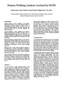
The weighted error was defined as the Mahalanobis norm of the pose parameter error. A clear advantage of the proposed algorithm can be observed for all subset sizes, although this advantage diminishes for large subsets, as in Fig. 2. Note that the graphs are not always monotonic. This is due to the specific measurement errors of the selected points, which affect the quality of the result. 2) Robot Experiment: In this experiment, a video camera with a resolution of 720 428 pixels was attached to a robotic arm (see Fig. 6). This arm can be manipulated in 6 DOF and supplies the trajectory in which it was maneuvered up to submillimetric accuracy. The positional information that was gathered from the robot was not used during the navigation task but rather was collected and saved as a ground truth for the algorithm evaluation. Six different scenarios were examined. These scenarios were a result of three scenes with different landmark constellations and two tasks to be performed. The first scene contained 90 coplanar landmarks homogeneously dispersed on a rectangular grid [see Fig. 7(a)]). Only 34 landmarks from the first scene were kept in the second: the upper 30 (forming a dense cluster) and 4 additional landmarks, widely dispersed in the lower part of the scene [see Fig. 7(b)]. The third scene was constructed from 34 landmarks lying on three orthogonal planes. Once again, 30 of them were located in a relatively dense cluster while the other 4 were dispersed in different locations [see Fig. 7(c)]. Using subsets of these landmarks, the robotic arm was supposed to perform two types of tasks: one was to accurately move along a predefined trajectory (path-following task), and the other was to keep a predefined target in a fixed location on the image (referred to as the sight) for as long as the camera was in motion (photographing or targeting task).
While the camera was in motion, landmark subsets were selected whenever required: when one of the landmarks left the field of view, or after the camera pose shifted beyond a certain threshold. As part of the control loop, the camera pose was constantly estimated on the basis of the selected landmarks and, as a consequence, the robotic arm trajectory was periodically adjusted. Fig. 7 shows examples for the selection results when using the proposed algorithm in the different scenarios.1 Note that in the nonhomogeneous landmark constellations the distant landmarks were always selected by the algorithm. This conforms to the intuition discussed in Section VI-A. For each examined scenario, subsets of different sizes were tested (6–15 landmarks). For each subset size, ten experiments were performed: in five of them the subsets were selected using the proposed algorithm while in the others the subsets were selected arbitrarily for purposes of comparison. The mean and maximum task-related errors are presented in Figs. 8 and 9. In all these figures the solid line represents the errors obtained when using the selection algorithm, and the dashed line represents the errors obtained when selecting the subsets arbitrarily. For the path-following task, the 3-D distance between the ground-truth camera location and the predefined trajectory was computed. For the photographing task, the target was located in the captured images at subpixel accuracy and its 2-D distance from the predefined sight was computed. It can be observed in all the experiments that there is a clear advantage 1Supplementary downloadable material provided by the authors is available at http://ieeexplore.ieee.org. This includes video files of the six examined scenarios with the selected landmarks at any moment along the trajectory. For the photographing experiments, additional videos are supplied showing the target-to-sight alignment during the experiments, with and without the selection algorithm. This material is 21.8 MB in size.
LERNER et al.: LANDMARK SELECTION FOR TASK-ORIENTED NAVIGATION
503
Fig. 8. Mean and maximal millimetric errors obtained for different subset sizes when a path following task was performed. In (a) and (b), the first landmark constellation was used, in (c) and (d), the second constellation, and in (e) and (f), the third constellation. Solid line—the error obtained when using the selection algorithm, dashed line—the error obtained when selecting the subsets arbitrarily.
Fig. 9. Mean and maximal projection errors (in pixels) obtained for different subset sizes when a photographing task was performed. In (a) and (b), the first landmark constellation was used, in (c) and (d), the second constellation, and in (e) and (f), the third constellation. Solid line-the error obtained when using the selection algorithm, dashed line-the error obtained when selecting the subsets arbitrarily.
to utilizing the proposed algorithm. As could be expected, the merit of the selection algorithm becomes more significant when the subset size decreases and when the distribution of the available landmarks is nonhomogeneous. One illustration of this is the vanishing gap between the mean photographing errors in Fig. 9(a) as the subset size increases. This is due to the homogeneous ordering of the landmarks in that experiment.
APPENDIX I PROOF OF THE GRADE FUNCTION CONVEXITY In this appendix, we present a convexity proof for the objective function of the relaxed selection problem grade
VII. CONCLUSION In this paper, a new algorithm for landmark selection was proposed. Due to performance limitations, a real-time navigation system can usually use only a small number of landmarks to compute the camera pose. It was shown that by defining the specific task requirements in the form of a requirements matrix, different subsets from the available landmarks are automatically selected. The obtained subset yields minimal uncertainty for the pose parameters according to the Mahalanobis metric, which is defined using the requirements matrix. Simulations and experimentation verify the advantages of integrating the proposed algorithm in real-time navigation systems.
(27) where
grade
(28)
, It is shown that the objective function grade is convex on . and thus maintains its convexity on any convex subset of Since each of the constraints in the relaxed problem defines a convex set (half-space or hyperplane), so does their intersection,
504
IEEE TRANSACTIONS ON ROBOTICS, VOL. 23, NO. 3, JUNE 2007
and therefore grade is convex on the problem’s feasible set. As a result, a search for a local minimum will surely lead to the global minimum as well. Proof: There are several methods for proving function convexity. The line restriction method, which is used in this proof, relies on the following lemma. be defined as Lemma 3: Let
and its transthe multiplication of this matrix by pose from each side does not affect its positiveness. Thus, the trace is activated on a positive semi-definite matrix, which yields a nonnegative value, as desired. ACKNOWLEDGMENT
grade
The authors would like to thank Prof. A. Nemirovski for enlightening discussion about the formulation of the problem as an SDP.
where the domain of is is feasible . Then, grade is convex iff is convex (in ) for any feasible and . Substituting (28) in the above definition yields
REFERENCES
(29) where (30) In order to show that is convex, it is proved that its second derivative is nonnegative. The following two equations are required for the derivations: (31) (32) and scalar . Therefore, the first derivative of
for any matrix is
(33) where the matrix
is defined as (34)
Next, the second derivative of
is obtained by
(35) In the last step of the above derivations, we used a circular permutation of the matrices inside the trace. Such a permutation is assumed to keeps the trace value unchanged. Since be feasible, is a symmetric positive semi-definite matrix and so is its inverse . Therefore, can be decomposed using , where is a the Cholesky decomposition, as real matrix. Once again the circular permutation of the matrices inside the trace will be used (36) Because
and
are symmetric matrices, it is clear that . Taking into account that ,
[1] D. DeMenthon and L. Davis, “Model-based object pose in 25 lines of code,” Int. J. Comp. Vision, vol. 15, no. 1–2, pp. 123–141, 1995. [2] P. David, D. DeMenthon, and R. Duraiswami, “Simultaneous pose and correspondence determination using line features,” in Proc. IEEE Conf. Comp. Vis. Pattern Recognit., 2003, pp. 424–431. [3] D. Philip, D. DeMenthon, and R. Duraiswami, “SoftPOSIT: Simultaneous pose and correspondence determination,” in Proc. Eur. Conf. Comput. Vis., 2002, pp. 698–714. [4] R. Haralick, H. Joo, C. Lee, X. Zhuang, V. Vaidy, and M. Kim, “Pose estimation from corresponding point data,” IEEE Trans. Syst. Man. Cybern,, vol. 19, no. 6, pp. 1426–1446, Dec., 1989. [5] Y. Hel-Or and M. Werman, “Absolute orientation from uncertain point data: A unified approach,” in Proc. IEEE Conf. Comp. Vision Patt. Recog., 1992, pp. 77–82. [6] Y. Liu, T. Huang, and O. Faugeras, “Determination of camera location from 2-d to 3-d line and point correspondences,” IEEE Trans. Pattern Anal. Mach. Intell., vol. 12, no. 1, pp. 28–37, Jan. 1990. [7] D. Burschka, J. Geiman, and G. Hager, “Optimal landmark configuration for vision-based control of mobile robots,” in Proc. IEEE Int. Conf. Robot. Autom., 2003, pp. 3917–3922. [8] S. Se, D. Lowe, and J. Little, “Vision-based mobile robot localization and mapping using scale-invariant features,” in Proc. IEEE Int. Conf. Robot. Autom., 2001, pp. 2051–2058. [9] C. Harris, “Geometry from visual motion,” in Active Vision. Cambridge, MA: MIT Press, 1993, pp. 263–284. [10] A. J. Davison, “Real-time simultaneous localisation and mapping with a single camera,” in Proc. IEEE Int. Conf. Comp. Vis., 2003, pp. 1403–1410. [11] J. Diebel, K. Reutersward, J. Davis, and S. Thrun, “Simultaneous localization and mapping with active stereo vision,” in Proc. Conf. Intell. Robots Syst.(IROS), 2004, pp. 3436–3443. [12] C. Tomasi and J. Shi, “Good features to track,” in Proc. IEEE Conf. Comp. Vis. Pattern Recognit., 1994, pp. 593–600. [13] C. Tomasi and T. Kanade, “Detection and tracking of point features,” Carnegie Mellon University, Tech. Rep. CMU-CS-91-132, Apr. 1991 [Online]. Available: citeseer.ist.psu.edu/tomasi91detection.html [14] P. Sala, R. Sim, A. Shokoufandeh, and S. Dickinson, “Landmark selection for vision-based navigation,” IEEE Trans. Robot., vol. 22, no. 2, pp. 334–349, Feb. 2006. [15] A. Bruckstein, R. Holt, T. Huang, and A. Netravali, “Optimum fiducials under weak perspective projection,” Int. J. Comp. Vis., vol. 35, no. 3, pp. 223–244, 1999. [16] K. Sutherland and W. Thompson, “Inexact navigation,” in Proc. IEEE Int. Conf. Robot. Autom., 1993, pp. I:1–I:7. [17] R. Haralick, “Propagating covariance in computer vision,” Int. J. Pattern Recognit. Artif. Intell., vol. 10, pp. 561–572, 1996. [18] Matlab Optimization Toolbox. 1995 [Online]. Available: http://www. mathworks.com/products/optimization/ [19] A. Ben-Tal and A. Nemirovski, Eds., Lectures on Modem Convex Optimization, ser. MPS-SIAM Series on Optimization. Philadelphia, PA: So. Ind. Appl. Math., 2001. [20] Y. Nesterov and A. Nemirovskii, Interior Point Polynomial Methods in Convex Programming: Theory and Applications. Philadelphia, PA: Society for Industrial and Applied Mathematics, 1994. [21] F. Alizadeh, “Interior point methods in semidefinite programming with applications to combinatorial optimization,” SIAM J. Optim., vol. 5, no. l, pp. 13–51, 1995. [22] C. Helmberg, F. Rendl, R. J. Vanderbei, and H. Wolkowicz, “Art iriifSor-point method for semidefinite programming,” SIAM J. Optim., vol. 6, pp. 342–361, 1996. [23] S. Benson, Y. Ye, and X. Zhang, DSDP Toolbox. [Online]. Available: http://www.unix.mcs.anl.gov/~benson/dsdp/ [24] K. Fujisawa, M. Kujima, K. Nakata, and M. Yamashita, SDPA Toolbox. [Online]. Available: http://grid.r.dendai.ac.jp/sdpa/ [25] J. Sturm, SeDumi Toolbox. [Online]. Available: http://fewcal.kub.nl/ sturm/software/sedumi.html
LERNER et al.: LANDMARK SELECTION FOR TASK-ORIENTED NAVIGATION
Ronen Lerner received the B.Sc. degree in computer science and mathematics from the University of Haifa, Haifa, Israel, in 2000 and the M.Sc. degree from the Technion—Israel Institute of Technology, Haifa, Israel, where he is currently working toward the Ph.D. degree in the Computer Science Department. His current research interest is in vision-based navigation.
Ehud Rivlin (M’90) received the B.Sc. and M.Sc. degrees in computer science and the MBA degree from the Hebrew University, Jerusalem, Israel, and the Ph.D. degree from the University of Maryland, College Park. Currently, he is an Associate Professor in the Computer Science Department, Technion-Israel Institute of Technology, Haifa, Israel. His current research interests are in machine vision and robot navigation.
505
Ilan Shimshoni (M’92) was born in Israel in 1959. He received the B.Sc. degree in mathematics and computer science from the Hebrew University, Jerusalem, Israel, in 1984, the M.Sc. degree in computer science from the Weizmann Institute of Science (1989), Rehovot, Israel, and the Ph.D. degree in computer science from the University of Illinois at Urbana Champaign in 1995. He spent three years as a Postdoc in the Computer Science Department in the Technion-Israel Institute of Technology, Haifa, Israel, and then several years in the Industrial Engineering Department. He joined the faculty of the Department of Management Information Systems, Haifa University, Haifa, Israel, in 2005, and is currently the Chair of that department. He also spent a year on sabbatical at Rutgers University, New Brunswick, NJ. He served as a committee member of all major conferences in computer vision. His research interests are in the fields of computer vision, robotics, and computer graphics specializing mainly in applications of statistical methods in these fields.