World Academy of Science, Engineering and Technology Vol:5 2011-01-26
Lattice Boltzmann Simulation of Binary Mixture Diffusion Using Modern Graphics Processors
International Science Index Vol:5, No:1, 2011 waset.org/Publication/11416
Mohammad Amin Safi, Mahmud Ashrafizaadeh, Amir Ali Ashrafizaadeh
Abstract—A highly optimized implementation of binary mixture diffusion with no initial bulk velocity on graphics processors is presented. The lattice Boltzmann model is employed for simulating the binary diffusion of oxygen and nitrogen into each other with different initial concentration distributions. Simulations have been performed using the latest proposed lattice Boltzmann model that satisfies both the indifferentiability principle and the H-theorem for multi-component gas mixtures. Contemporary numerical optimization techniques such as memory alignment and increasing the multiprocessor occupancy are exploited along with some novel optimization strategies to enhance the computational performance on graphics processors using the C for CUDA programming language. Speedup of more than two orders of magnitude over single-core processors is achieved on a variety of Graphical Processing Unit (GPU) devices ranging from conventional graphics cards to advanced, high-end GPUs, while the numerical results are in excellent agreement with the available analytical and numerical data in the literature. Keywords—Lattice Boltzmann model, Graphical processing unit, Binary mixture diffusion, 2D flow simulations, Optimized algorithm. I. INTRODUCTION
B
mixture diffusion is a complex process that has several applications in fluidic systems such as chemically reacting flows, gas purification, pollutant dispersion and so forth. Diffusion of oxygen and nitrogen, discussed in the present work, is of a crucial importance since these two elements are the major constituents of atmospheric air and their diffusion plays a great role in combustion systems and nitrogen/oxygen purification processes. However, such flows generally involve mass and momentum diffusion of two or more species of multiple phases dealing with complex geometries and boundary conditions such as adsorption and phase change. These conditions make the whole process difficult to be described using the conventional continuum assumptions as they involve many small scale transport INARY
M. A. Safi is a MSc. student of mechanical engineering at Isfahan University of Technology. He is Also with the university’s High Performance Computing Center. Isfahan University of Technology, Isfahan, 84156-8311, Iran (corresponding author; e-mail:
[email protected]). M. Ashrafizaadeh is an assistant professor of mechanical engineering at Isfahan University of Technology and the head of university’s High Performance Computing Center. Isfahan University of Technology, Isfahan, 84156-8311, Iran (e-mail:
[email protected]). Amir Ali Ashrafizaadeh is a BSc. student of mechanical engineering at Isfahan University of Technology, Isfahan, 84156-8311, Iran. (e-mail:
[email protected]).
phenomena. Recently, there has been a great interest in applying kinetic theory to capture the delicate diffusion processes in such flows and several models have been proposed to extend kinetic-based lattice Boltzmann Models (LBM) to these problems. Early implementations e.g. [1], [2] were unable to satisfy either the indifferentiability principle (recovering a simple component Lattice Bhatnagar-GrossKrook (LBGK) expression by setting the same properties for both species), or the H-theorem and some were limited to small molecular mass ratios [3]. A recent consistent model proposed by Arcidiacono et al. [4]-[6] is proved to satisfy both the indifferentiability principle and the H-theorem and is stable over a wide range of mass ratios. The model is based on the so called entropic LBM and successfully proved to recover the Navier-Stokes and the Stephan-Maxwell diffusion equations. Despite the outstanding accuracy and flexibility of the new model, the entropic nature of the algorithm increases the computational cost of a binary mixture simulation to much more than twice, compared to single component LBGK simulations. Considering such a high computational load and the extremely small time scales associated with diffusion phenomena in these problems, improving the computational efficiency is a real challenge especially when the model is to be applied to flows with complex geometries and/or boundary conditions. In addition, due to its highly explicit nature of solution, lattice Boltzmann method is widely accepted to be a well suited candidate for parallelization. Besides using multicore CPUs and compute clusters, some researchers have performed parallel LBM simulations on manycore Graphical Processing Units (GPU), using graphical languages such as OpenGl [7], [8]. By the advent of the modern programmable graphics cards and new graphical programming language, CUDA, in 2006 by nVIDIA, there has been a great interest in exporting conventional real world computational fluid dynamics solvers to graphics processors in order to enhance the previously expensive, time-consuming flow simulations, thereby lowering their total simulation time. However, the LBM implementations so far, have been restricted to single component fluid flows using elementary models such as single or multiple relaxation time LBGK [9]-[17], and there have not been any serious effort to implement complex multicomponent gas mixtures on GPUs. Moreover, the proposed multi-component entropic model of Arcidiacono et al. still inherits its fully explicit nature and massive parallelization is viable through the new heterogeneous, general purpose GPU
737
World Academy of Science, Engineering and Technology Vol:5 2011-01-26
International Science Index Vol:5, No:1, 2011 waset.org/Publication/11416
architectures. Recently, the computational power of modern GPUs has exceeded that of PC-based CPUs by far i.e. more than one order of magnitude while being available for a comparable price [9]. NVIDIA’s new gaming cards such as GeForce 9800 GT has been observed to deliver over 330 × 109 single precision Floating point Operations Per Second (330 Giga FLOPS) and its recently released Tesla C1060 computing cards have even a much greater peak performance of about 1 TeraFlops for single and 78 Giga Flops for double precision computations. In comparison, the theoretical peak performance of the Intel Core 2 Duo 3.0 GHz is only 24 GFLOPS for double and 48 GFLOPS for single precision computations [9]. A. Previous works Several papers have discussed porting conventional LB solvers to graphics processors and enhancing the computational performance of such solvers. Tolke [9] developed a highly optimized 2D lattice Boltzmann model using CUDA and reported one order of magnitude performance gain compared to standard CPU only codes. The main point of his work was using shared memory buffer to prevent inefficient memory transactions. Later on, Tolke and Krafczyk [10] reported efficiency gain of up to two orders of magnitude using a CUDA based lattice Boltzmann kernel for 3D flow simulations. Kaufman, Fan and Petkov [11] have advocated the use of GPU clusters for large scale LBM simulations and for high performance computing. Kuznik, Obrecht, Rusaouen and Roux [12] employed a high-end platform equipped with nVIDIA GT200 to simulate lattice Boltzmann flows and even performed double precision calculations on their GPU. Zadehgol, Ashrafizaadeh and Safi [13] implemented a lattice Boltzmann flow solver in a square cavity on different kinds of single GPUs and delivered a performance gain of up to 180 times over single CPUs. Bernasch, Fatica, Melchionna, Succi and Kaxiras [14] ported a 3D solver for flow in human coronary artery using D3Q19 model and obtained more than 900 Mega Lattice Update Per Second (MLUPS) by eight parallel GPUs. They employed some ad hoc techniques to manage the solid and fluid nodes separately and doing so, they prevented the calculations on inactive nodes. Ribbrock, Geveler, Goddeke and Turek [15] presented a solution for a two-dimensional shallow water flow and obtained eightfold speedup over multithreaded CPU code by means of a single GPU device. Obrecht, Kuznik, Tourancheau and Roux [16] suggested a set of new optimization instructions in their research and could extract more than %86 of the device throughput in their memory transactions without engaging the precious shared memory buffer, this way saving it for other instructions. Safi, Ashrafizaadeh and Zadehgol [17] implemented simulations of 2D flow over a column of cylinders on multiple GPUs and discussed some critical optimization approaches such as increasing hardware occupancy to enhance the computational performance.
B. Paper Contribution and Overview In this paper an efficient GPU based implementation of a LB model for time dependent binary diffusion of oxygen and nitrogen with a distinct initial concentration distribution is presented. The present parallel version is based on a serial solver previously developed by our research group [18]. A comparison of the present results with those of analytical data shows how accurately the present results can mimic the time varying analytic solution for such a basic but complex phenomenon. The LB model for binary mixtures is describes in section II. A brief review on GPU programming model is presented in Section III. Section IV discusses the optimization strategies and the programming methodology applied to the present implementation. The results, including time-elapsed concentration variation of each species as well as performance measurement for different platforms are presented in Section V. Conclusions are reported in section VI. II. LATTICE BOLTZMANN MODEL FOR BINARY MIXTURES In the lattice Boltzmann model the continuous spectrum of particle velocities has been replaced by a set of discrete velocities of imaginary particles which are forced to move on a lattice structure only. As a result of this simplification, the solution of the Boltzmann equation has become considerably easier and at the same time some limitations such as low Mach number, have been imposed on the standard model. A direct extension of the discrete lattice Boltzmann equation for multicomponent mixtures can be written as
∂t f ji + c jiα ∂α f ji = Ωji
(1)
where i = 0,..., N , with N being the number of discrete lattice velocities c jiα , α = {x, y, z} , and Ωji is the collision term. The above equation is further expanded based on fast-slow decomposition of motion in the vicinity of quasi-equilibrium state, as proposed in [19], which guarantees the positive entropy production of the process and hence satisfies the Htheorem. Therefore, the process is composed of a fast relaxation from the initial state f to the quasi-equilibrium f * and then moving slowly from the quasi-equilibrium state f * towards the equilibrium f eq . Expressing the two motions as BGK terms, the final collision term for the LB equation takes the following form for each species j : Ω ji = −
1
τ1 j
( f ji − f ji∗ ) −
1
τ2 j
( f ji∗ − f jieq )
(2)
where τ 1 j and τ 2 j are the two relaxation times corresponding to each of the relaxation stages, with the condition τ 2 j ≥ τ 1 j which ensures the stability of the model and puts a limit on the admissible Schmidt number ν / DAB , where ν is the kinematic viscosity and DAB is the binary diffusion coefficient. This bounding on the Schmidt number is further discussed at the
738
World Academy of Science, Engineering and Technology Vol:5 2011-01-26
where uα = Jα / ρ is the mixture velocity in α direction, and ρ = ρ A + ρB .
end of this section. The moments of each component are defined as, ρ j = ∑ f jieq
,
j
The quasi-equilibrium function f ji∗ can be obtained using
j jα = ∑ f ji c jiα
(3)
i
Pjeqαβ = ∑ f jieq c jiα c ji β , i
eq Qeq jαβγ = ∑ f ji c jiα c ji β c jiγ i
where ρ j , J jα , Pjαβ and Q jαβγ
are the density, the
International Science Index Vol:5, No:1, 2011 waset.org/Publication/11416
momentum, the pressure tensor and the third order moment of component j , respectively. For the D2Q9 model considered in this paper, the discrete lattice velocities are ⎧ ⎪ i=0 ⎪(0,0) ⎪ r ⎪ ⎧ ⎛ π (i − 1) ⎞ ⎛ π (i − 1) ⎞ ⎫ cij = ⎨c j ⎨cos ⎜ i = 1to 4, ⎟ ,sin ⎜ ⎟⎬ 2 ⎠ ⎝ 2 ⎠⎭ ⎪ ⎩ ⎝ ⎪ ⎪c 2 ⎨⎧cos ⎛ π (2i − 9) ⎞ ,sin ⎛ π (2i − 9) ⎞ ⎫⎬ i = 5 to 8 ⎜ ⎟ ⎜ ⎟ ⎪⎩ j 4 4 ⎠ ⎝ ⎠⎭ ⎩ ⎝
(4)
j .The entropic nature of the model requires the minimization of the H-function defined by the following equation,
f ji
(6)
Wi
which will be minimized under the constraints of conservation of density of each species ρ j and the total mixture momentum J α = J A + J B . The corresponding weighting factor is:
⎧4 / 9 i = 0 ⎪ Wi = ⎨1 / 9 i = 1,K, 4 ⎪1 / 36 i = 5,K,8 ⎩
⎛ 2c − c 2 + 3u 2 α j j = ρ jWi ∏ ⎜ ⎜ c α =1 j ⎝
The standard BGK model can be easily recovered for a single component fluid from (2) and (10), where τ A = τ B = τ and m A = mB and hence the indifferentiability principle is proved to be valid. The relaxation times τ 1 j and τ 2 j for each component are related to transport coefficients of the flow by using the Chapman-Enskog expansion in the hydrodynamic limit, adapting it to simplify the conservation equations for each component, and then comparing them to standard NavierStokes and Stephan-Maxwell diffusion equations. The lengthy mathematical process is beyond the scope of this paper and the details can be found in [5]. The final set of equations for the relaxation times for each component are expressed as, τ1 j =
(7) τ2 j =
The cumbersome process of minimization leads to the following final equation for the equilibrium distribution function that is similar to that of a single component fluid,
f
(10)
(5)
where k B is the Boltzmann constant, T0 is a reference temperature and m j is the molecular mass of component
eq ji
(9)
The above equations lead to derivation of the quasiequilibrium function merely by substituting the velocity of the species u jα = J jα / ρ j instead of Uα in (8), therefore obtaining, r r f ji∗ ( ρ j , u j ) = f jieq ( ρ j , u j )
csj = k BT0 / m j
d
ρ j = ∑ f ji i
is defined as,
i
quasi-equilibrium variable. The selection directly depends on magnitudes of transport coefficients of the species and will be further elaborated at the end of this section. Here, for brevity, only the first approach is explained. Using the difference between momentums along with the previous conservation rules, one may eventually reach to the following set of constraints:
i
the speed of sound of the components as c j = 3csj , where csj
j
minimization problem, or the stress tensor Pjαβ as the extra
J jα = ∑ f ji c jiα
where the magnitude of c j for each component is related to
H = ∑∑ f ji ln
two complementary approaches; taking either the difference between the momentum J α of the mixture and the momentum J jα of the component j as an extra constraint for the
⎞⎛ 2u + c 2 + 3u 2 α j ⎟⎜ α ⎟⎜ c j − uα ⎠⎝
c jiα
⎞ cj ⎟ ⎟ ⎠
(8)
μj nk BT0 DAB mAB X AX BP
(11)
where μ j is the dynamic viscosity of the component, X A , X B are the mole fractions of component A and B, n is the total number of moles in the mixture, P = k BT0 n is the mixture pressure, and mAB = ρ A ρ B / ( ρ A + ρ B ) is the mixture reduced mass. Considering these two equations, the mentioned restriction on the Schmidt number can now be introduced. Rewriting the Schmidt number as,
739
World Academy of Science, Engineering and Technology Vol:5 2011-01-26
and shared memories which will be discussed later. μj
Sc =
ρ j DAB
τ mAB = 1 τ2 X A X BP
(12)
The construction τ 1 j < τ 2 j leads to the following inequality: Sc j =
μj YY ≤ A B ρ j DAB X A X B
(13)
where Y j is the mass fraction of component j . Note that this restriction is a result of taking the difference between mixture momentum J α , and momentum of each component J jα as the extra quasi-equilibrium variable. The evaluation of quasiequilibrium function using the stress tensor Pjαβ as the extra
International Science Index Vol:5, No:1, 2011 waset.org/Publication/11416
constraint leads to a complementary inequality, Sc j ≥
YAYB X AXB
(14)
Deciding between the two models depends on which of the above inequalities is satisfied, considering the magnitudes of the species transport coefficients, as mentioned before. III. OVERVIEW OF GPU PROGRAMMING AND CUDA CUDA is a new computational architecture introduced by NVIDIA Corporation that includes heterogeneous computing innovations at both software and hardware levels. It has been designed for utilizing graphical processing units (GPUs) for non graphical and general purpose computations. The NVIDIA’s “C for CUDA” programming language is an extension to the conventional C language and allows the programmer to define new class of functions, called kernels which will be launched on GPU. By calling each kernel, N different CUDA threads will be executed in parallel, contrary to only once like regular C functions in serial algorithms [19]. In GPU terminology, the graphical processing unit is referred to as the “Device” while the CPU is referred to as the “Host”. As it can be seen in Fig. 1, the GPU is equipped with many cores (a number of multiprocessors, each constitutes of eight processors) as processing units, and different types of memories. In a typical CUDA program, data is first transferred from the host to the device. As shown in Fig. 2, the host then launches special GPU functions (kernels), which will run the program on the many cores of the device, in parallel, and finally the results are transferred back to the host. It is important to note that the maximum bandwidth and latency of various memory types of the GPU are quite different. The global device memory (DRAM of the GPU) is large; however, it is much slower than the shared memory which is a limited source of on-chip memory for each multiprocessor. Therefore, in order to achieve the best performance, there should be a careful balance between storing the variables on the global
Fig. 1 A simple graphical representation of host and device
As mentioned before, CUDA creates several threads which will run the kernel commands in parallel. Since the number of threads could be different from the number of available cores, the execution of threads on these available cores is managed by CUDA. Threads are packed in groups which are called “blocks”. A “grid” in CUDA terminology is a batch of thread blocks, and its dimension should be defined in accordance with the size of the problem. All the threads in a block will be passed to one multiprocessor to be processed and these threads can simultaneously access the shared memory while this is not possible for threads running on different blocks. Once a GPU core completes the execution of a thread, it can be utilized by CUDA for the execution of the next thread in line.
Fig. 2 Grids of blocks and thread of each block in the GPU programming model
One critical point in writing an efficient CUDA code is to appropriately manage the memory accesses. Most importantly, the programmer should pay special attention to the memory alignments. This, along with the concept of hardware occupancy will be discussed in the following sections.
740
International Science Index Vol:5, No:1, 2011 waset.org/Publication/11416
World Academy of Science, Engineering and Technology Vol:5 2011-01-26
A. Memory access management Achieving the maximum performance for memory transactions within different memories requires the following qualifications to be met: • Memory access coalescence in global memory • Preventing bank conflict in shared memory Since the latency of memory accesses in the device memory is rather high, the hardware would combine a number of memory calls into single packs or groups of data and transfers them all together. Depending on the type of the device, the memory size of these groups would be 32, 64, or 128 bytes. However, this requires the programmer to consider alignment in his memory calls [20], [21]. Memory alignment means that the pointer address value should always be a multiple of the size of the type of the variable. It is worthwhile to note that ignoring such principles would dramatically degrade the performance of the simulation and the memory bandwidth will drop to about 10 GB/s compared to its maximum of almost 100 GB/s [10]. Moreover, since the shared memory is made up of 16 separate memory banks, to prevent bank conflict within the shared memory space, the block size should be a multiple of 16. B. Hardware Occupancy Since each multiprocessor has a limited amount of registers and shared memory, it will have a certain capacity to accept threads. Therefore, keeping the multiprocessors of the GPU as busy as possible is vital to gain a good performance and is often referred to as occupancy which is the ratio of the number of active threads per multiprocessor to the maximum number of possible active threads [21]. It is up to the programmer to set the dimension of the blocks and the amount of shared memory and register for block threads to reach the maximum possible occupancy of the hardware. One should note that decreasing the allocated registers for each thread to a minimum count (in order to maximize the occupancy) will degrade the computational performance of kernel instructions. Therefore, care must be taken to find an appropriate balance while setting this parameter. IV. NUMERICAL OPTIMIZATIONS In order to satisfy the requirements mentioned in previous sections, the following steps were taken: • A structure consisting of 9 distinct arrays was used for different distribution functions. • Data transfer between the host and device is performed by means of one-dimensional buffers, therefore, onedimensional arrays are utilized. • The dimensions of the computational domain at least in one direction is multiple of powers of 2 (and preferably greater than 64 [20]), to satisfy the alignment requirements. • During the LBM propagation stage, transfer of data for the rest particles and for the north and south
directions, automatically satisfies the memory alignment requirements since under the above dimensional circumstances, the source and destination addresses are aligned with the size of the types of the variables. For the other directions; however, the use of the fast shared memory is preferred. • To engage the hardware as much as possible we have examined imposing different amounts of registers for each thread along with selecting an optimum size for our thread blocks. For the present study, we have analyzed several versions of our code, using the CUDA Visual Profiler provided by nVIDIA [22], to check whether we have reached the optimum possible memory alignment or not. Employing this useful tool, we were able to find the exact number of coalesced and uncoalesced memory transactions from or to the global memory, this way making sure that the misalign accesses are at the minimum level in the code. In addition to above conventional optimizations we have applied a new addressing scheme for the particular problem of interest in this paper. Here, we have two sets of distribution functions; one for Oxygen and the other for Nitrogen. In a serial programming approach, one has to define two sets of structures, launch separate functions for each component and solve them in serial. On the other hand, updating the distributions for each species in a particular grid point in the computational domain is absolutely independent from the other species and hence they can be solved at the same time. In a heterogeneous programming model of GPUs, the programmer can combine the two sets of distribution functions in a single grid of blocks and launch them all together. As such, instead of defining a set of distinct arrays for each component a structure of 9 arrays is defined. Each array contains the distribution functions of the first component, followed by the distributions of the second one, so that we can preserve the alignment requirements. Fig. 3 and Fig. 4 show how the separate grids of blocks will constitute a single grid, and how the two arrays combine, forming a single array, respectively. Using a single structure of arrays also brings this benefit of reducing the required shared memory and registers for storing the kernel arguments and managing data accesses inside the kernel. The only disadvantage of such an approach might be a rather complicated addressing scheme for the arrays in the kernel, since the array elements corresponding to the second species will be addressed by an offset of the size of the computational domain as depicted in Fig. 3.
741
World Academy of Science, Engineering and Technology Vol:5 2011-01-26
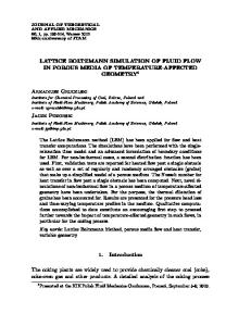
where X initial is the initial mole fraction of component j j is the initial mole fraction difference along the x axis, ΔX initial j and D is the binary diffusion coefficient. Fig. 5 shows an excellent agreement between the analytical solution and LB simulations for several time steps using graphical processing unit on a computational domain of typical size of 16 x 1024. Note that the simulations have been performed using single precision floating point operations.
International Science Index Vol:5, No:1, 2011 waset.org/Publication/11416
Fig. 3 The grids corresponding to the two distinct computational domain are combined to form a single one and are solved in parallel.
Fig. 4 The suggested array configuration scheme for each of the 9 discrete velocities, k, applied in this work. Here, F1 and F2 correspond to Oxygen and Nitrogen, respectively and F corresponds to the new binary array.
V. RESULTS AND DISCUSSION A. Hydrodynamics The geometry of the problem consists of a rectangular 2D box with an initial concentration of oxygen at the central region, and nitrogen distributed on both sides along the axial direction x with the following profile: X O2 = 85% , X N2 = 15% if - h / 2 ≤ X ≤ h / 2 X O2 = 46% , X N2 = 53% if - h / 2 ≥ X or h / 2 ≤ X
(15)
and includes the binary diffusion of the two gases from both sides, where h is the length of the Oxygen concentration zone. Simulating more abrupt changes in initial molar profile is a real computational challenge and care must be taken to choose a proper initial distribution, because under intense molar differences the flow is likely to allow some artificial pressure waves to grow and disturb the numerical results [18]. Periodic boundary conditions are imposed at the top and bottom of the computational domain and the unknown incoming distributions at x = 0, x = L (where L is the length of the domain) are approximated as
f * ( ρ j (t − 1), u = 0) , and
ρ j (t − 1) is the density of the component j evaluated at the
previous time step [23]. The above problem has the following analytical solution which expresses the evolution for the mole fraction of each component as a function of time [18]: X j = X initial + j
ΔX initial j 2
[erf (
h+x 4 Dt
) + erf (
h−x 4 Dt
)]
Fig. 5 Time evolution for the molar fraction of Oxygen from its initial distribution. The solid lines indicate the LB predictions and the symbols correspond to the analytical answer for the same problem; time step 1000 (diamonds); 3000 (circles); 6000 (squares), and 9000 (crosses).
B. Numerical Performance The technical specifications of the two GPUs in hand for our simulations are given in Table I. Two personal computer platforms are also used here. The first one is a regular Intelbased PC equipped with an Intel Core 2 Duo 3.0 GHz CPU and a GeForce 9800 GT GPU and the second platform is a high-end workstation equipped with 16 Intel Xeon x5570 2.93 GHz cores, and three Tesla C1060 GPUs. Table II and Table III show the best computational performance of single and even double precision runs, where applicable, in Millions of Lattice Updates per Second or MLUPS. Note that since the computational resources (especially the number of processor cores) are not the same for each of the platforms, the optimum size of the computational domain may vary on different devices.
(16)
742
World Academy of Science, Engineering and Technology Vol:5 2011-01-26
TABLE I COMPARISON OF THE MAJOR SPECIFICATIONS OF GEFORCE 9800 GT AND TESLA C1060 GPUS
GPU TYPE Geforce 9800 GT Tesla C1060
Single/double precision cores
Memory (GB)
Processor Clock (GHz)
Memory Bandwidth (GB/sec)
112 / 0
1
1.5
57.6
240 / 30
4
1.3
102
available memories. It is evident from Table III that the computational capability of double precision for Tesla C1060 is much lower than its single precision performance. Fortunately, this deficiency has been alleviated in the new Tesla C2050 generation; where the peak performance of double precision computations is increased to more than 500 Giga FLOPS. VI. CONCLUSIONS
International Science Index Vol:5, No:1, 2011 waset.org/Publication/11416
TABLE II NUMERICAL PERFORMANCE OF GEFORCE 9800 GT
Block size
Register count
Domain size (Y x X)
Occupancy
Performance (MLUPS)
64 128 192 256 256 256 256
30 30 30 30 30 30 30
64 x 1024 64 x 1024 64 x 1536 64 x 1024 128 x 1024 256 x 1024 512 x 1024
33% 33% 25% 33% 33% 33% 33%
113 121 120 123 132 134 143
TABLE III NUMERICAL PERFORMANCE OF TESLA C1060
Block size
Register count
Domain size (Y x X)
Occupancy
Performance (MLUPS) single/double
64 128 192 256 256 256 256
31 31 31 31 31 31 31
210 x 2024 210 x 2024 210 x 2112 210 x 2024 210 x 2024 420 x 3328 420 x 3804
50% 50% 38% 50% 50% 50% 50%
239 / 26 252 / 26 260 / 23 277 / 26 298 / 25 300 / 25 301 / 25
As it can be seen, the performance of single precision simulations will be more than 143, and 301 MLUPS on Geforce 9800 GT, and Tesla C1060, respectively, while ,regardless of the size of the domain, the performance on a single core intel Core2 Dou and Intel Xeon CPUs barely exceeds 1.1 and 1.4 MLUPS, respectively. This means that the best GPU performance by Tesla C1060 is extremely faster than that of the best CPU based code on Intel Xeon by a factor of almost 200, which is quite impressive. The register counts have been adjusted to reach a balance between the occupancy and the instructions’ performance, and the maximum affordable occupancy was evaluated to be not greater than 50 percent on Tesla C1060. The highlighted rows in both tables point to careless selections of block size which results in lower occupancy and hence a relatively lower performance. It can be seen that increasing the size of the thread blocks has a certain positive effect on the performance, since it allows for more coalesced memory transactions. Moreover, increasing the size of the domain up to certain values causes most of the computational resources to be engaged and hence increases the speed. Apparently, choosing 210 or 420 as the dimension in the y direction contributes to this effect on Tesla C1060 as it causes the computational grid to be aptly distributed on the existing number of multiprocessors and
A 2D lattice Boltzmann flow solver for binary diffusion of oxygen and nitrogen has been developed for the GPU. We used an optimized algorithm to employ the maximum computational power of GPUs using both conventional optimization strategies and a novel addressing scheme to solve the transport equations for both species in parallel. We have shown that, even using a relatively low cost graphical processing unit such as a GeForce 9800 GT, it is possible to obtain more than 100 times speed up for such a slow pace 2D LBM flow simulation. Using more advanced GPUs (TESLA C1060), more than 200 times speed up is achievable, bringing the long, wearisome simulation times down to just a few minutes. These results encourage the implementation of more sophisticated, 3D multi-component flow implementations on GPUs and indicate that similar speedups will be attainable for these problems. Preliminary results are quite promising and are subject to future publications. ACKNOWLEDGMENT Financial support of the Iranian ministry of science, research and technology and the aviation industries is acknowledged. REFERENCES [1] [2] [3]
[4]
[5]
[6]
[7]
[8]
[9]
743
X. Shan and J. Doolen, “Diffusion in a multicomponent Lattice Boltzmann model,” in , Physical Review E., Vol. 54, 1996. L .S. Luo and S. S. Girimaji, “Theory of Lattice Boltzmann Method: Two fluid model for binary,” in Physical Review E., Vol. 67, 2003. M. E. McCracken and J. Abraham, “Lattice Boltzmann Method for Physical binary mixtures with different molecular weights,” in Review E., Vol. 71, 2005. S. Arcidiacono, S. Ansumli, I. V. Karlin J. Mantzaras and K.B. Boulouchos, “Entropic Lattice Boltzmann Method for simulation of binary mixtures,” in Mathematics and Computers in simulation, Vol. 72, No. 2-6, pp. 79-83, 2006. S. Arcidiacono, I. V. Karlin J. Mantzaras and C. Foruzakis, “Lattice Boltzmann model for the simulation of multicomponent mixtures,” in Physical Review E., Vol. 78, No. 4, 2008. S. Arcidiacono, J. Mantzaras and I. V. Karlin “Lattice Boltzmann simulation of catalytic reactions,” in Physical Review E., Vol. 76, No. 4, 2007. W. Li, Z. Fan, X. Wei and A. Kaufman, “GPU-based flow simulation with complex boundaries,” in GPU Gems 2Pharr M., (ed) Addison Wesley: Boston, MA, 747-764, 2005. H. Zhu, X. Liu, Y. Liu and E. Wu, “Simulation of miscible binary mixtures based on Lattice Boltzmann method,” in Comp. Anim. Virtual Worlds, 17, 403-410, 2008. J. Tolke, “Implementation of a Lattice Boltzmann kernel using the compute unified device architecture,” in computing and Visualization in Science, 2008.
International Science Index Vol:5, No:1, 2011 waset.org/Publication/11416
World Academy of Science, Engineering and Technology Vol:5 2011-01-26
[10] J. Tolke and M. Krafczyk, “TeraFLOP computing on a desktop PC with GPUs for 3D CFD,” in International Journal of Computational Fluid Dynamics, Vol. 22, No. 7, 2008. [11] A. Kaufman, Z. Fan and K. Petkof, “Implementing the Lattice Boltzmann model on commodity graphics hardware,” in Journal of Statistical Mechanics: Theory and Experiment, 2009. [12] F. Kuznik, C. Obrecht, G. Rusaouen and J. Roux, “LBM Based flow simulation using GPU computing processor,” in Comp. and Math. With App. Volume 59, Issue 7, pp. 2380-2392, 2010. [13] A. Zahehgol, M. Ashrafizaadeh, and M.A. Safi, “GPU implementation of a lattice Boltzmann flow solver”, in Proc. 18th Annual International Conference on Mechanical Engineering, Sharif University of Technology, Tehran, 2010. [14] M. Bernasch, M. Fatica, S. Melchionna, S. Succi and E. Kaxiras, “A flexible high-performance Lattice Boltzmann GPU code for simulation of fluid flows in complex geometries,” in Concurrency and Computation: Prac. Exper. 22, pp 1-14, 2010. [15] D. Ribbrock, M. Geveler, D. Goddeke and S. Turek, “Performance and accuracy of Lattice Boltzmann kernels on multi- and manycore architectures,” in Procedia Computer science 1, pp 239-247, 2010. [16] C. Obrecht, F. Kuznik, B. Tourancheau and J. Roux, “A new approach to the lattice Boltzman method for graphics processing units,” in Comp. Math. with App. 2010, to be published. [17] M. A. Safi, M. Ashrafizaadeh, and A. Zahehgol, “Implementing lattice Boltzmann fluid flow simulations on graphics processors”, in Proc. 13 Annual and 2nd international Fluid Dynamics Conference, University of Shiraz, Shiraz, 2010, submitted for publication. [18] Rastegari, A., "Simulation of gaseous mixtures in a packed bed of unfixed particles," Msc. Thesis, Isfahan University of Technology, 2008. [19] A.N. Ghorban and I. V. Karlin, in Physica A 206, 40, 1994. [20] nVIDIA, CUDA Programming Guide V3.0, 2010. [21] nVIDIA, CUDA Best Practice Guide V3.0, 2010. [22] nVIDIA, CUDA Visual Profiler V3.0.23, 2010. [23] S. S. Chikatamarla, S. Ansumali, and I. V. Karlin, in Europhys. Lett. 74, 215, 2006.
744