Jul 22, 2013 ... Identifies a leaf statement at a configuration hierarchy level. ; (semicolon). GUI
Conventions. • In the Logical Interfaces box, select. All Interfaces.
Junos® OS Layer 2 Overview, Routing Instances, and Basic Services Feature Guide for Routing Devices
Release
13.2
Published: 2013-07-22
Copyright © 2013, Juniper Networks, Inc.
Juniper Networks, Inc. 1194 North Mathilda Avenue Sunnyvale, California 94089 USA 408-745-2000 www.juniper.net This product includes the Envoy SNMP Engine, developed by Epilogue Technology, an Integrated Systems Company. Copyright © 1986-1997, Epilogue Technology Corporation. All rights reserved. This program and its documentation were developed at private expense, and no part of them is in the public domain. This product includes memory allocation software developed by Mark Moraes, copyright © 1988, 1989, 1993, University of Toronto. This product includes FreeBSD software developed by the University of California, Berkeley, and its contributors. All of the documentation and software included in the 4.4BSD and 4.4BSD-Lite Releases is copyrighted by the Regents of the University of California. Copyright © 1979, 1980, 1983, 1986, 1988, 1989, 1991, 1992, 1993, 1994. The Regents of the University of California. All rights reserved. GateD software copyright © 1995, the Regents of the University. All rights reserved. Gate Daemon was originated and developed through release 3.0 by Cornell University and its collaborators. Gated is based on Kirton’s EGP, UC Berkeley’s routing daemon (routed), and DCN’s HELLO routing protocol. Development of Gated has been supported in part by the National Science Foundation. Portions of the GateD software copyright © 1988, Regents of the University of California. All rights reserved. Portions of the GateD software copyright © 1991, D. L. S. Associates. This product includes software developed by Maker Communications, Inc., copyright © 1996, 1997, Maker Communications, Inc. Juniper Networks, Junos, Steel-Belted Radius, NetScreen, and ScreenOS are registered trademarks of Juniper Networks, Inc. in the United States and other countries. The Juniper Networks Logo, the Junos logo, and JunosE are trademarks of Juniper Networks, Inc. All other trademarks, service marks, registered trademarks, or registered service marks are the property of their respective owners. Juniper Networks assumes no responsibility for any inaccuracies in this document. Juniper Networks reserves the right to change, modify, transfer, or otherwise revise this publication without notice. Products made or sold by Juniper Networks or components thereof might be covered by one or more of the following patents that are owned by or licensed to Juniper Networks: U.S. Patent Nos. 5,473,599, 5,905,725, 5,909,440, 6,192,051, 6,333,650, 6,359,479, 6,406,312, 6,429,706, 6,459,579, 6,493,347, 6,538,518, 6,538,899, 6,552,918, 6,567,902, 6,578,186, and 6,590,785.
®
Junos OS Layer 2 Overview, Routing Instances, and Basic Services Feature Guide for Routing Devices 13.2 Copyright © 2013, Juniper Networks, Inc. All rights reserved. The information in this document is current as of the date on the title page. YEAR 2000 NOTICE Juniper Networks hardware and software products are Year 2000 compliant. Junos OS has no known time-related limitations through the year 2038. However, the NTP application is known to have some difficulty in the year 2036.
END USER LICENSE AGREEMENT The Juniper Networks product that is the subject of this technical documentation consists of (or is intended for use with) Juniper Networks software. Use of such software is subject to the terms and conditions of the End User License Agreement (“EULA”) posted at http://www.juniper.net/support/eula.html. By downloading, installing or using such software, you agree to the terms and conditions of that EULA.
ii
Copyright © 2013, Juniper Networks, Inc.
Table of Contents About the Documentation . . . . . . . . . . . . . . . . . . . . . . . . . . . . . . . . . . . . . . . . . . . . ix Documentation and Release Notes . . . . . . . . . . . . . . . . . . . . . . . . . . . . . . . . . . ix Supported Platforms . . . . . . . . . . . . . . . . . . . . . . . . . . . . . . . . . . . . . . . . . . . . . ix Using the Examples in This Manual . . . . . . . . . . . . . . . . . . . . . . . . . . . . . . . . . . ix Merging a Full Example . . . . . . . . . . . . . . . . . . . . . . . . . . . . . . . . . . . . . . . . x Merging a Snippet . . . . . . . . . . . . . . . . . . . . . . . . . . . . . . . . . . . . . . . . . . . . x Documentation Conventions . . . . . . . . . . . . . . . . . . . . . . . . . . . . . . . . . . . . . . . xi Documentation Feedback . . . . . . . . . . . . . . . . . . . . . . . . . . . . . . . . . . . . . . . . xiii Requesting Technical Support . . . . . . . . . . . . . . . . . . . . . . . . . . . . . . . . . . . . . xiii Self-Help Online Tools and Resources . . . . . . . . . . . . . . . . . . . . . . . . . . . xiii Opening a Case with JTAC . . . . . . . . . . . . . . . . . . . . . . . . . . . . . . . . . . . . . xiv
Part 1
Overview
Chapter 1
MX Series Routers . . . . . . . . . . . . . . . . . . . . . . . . . . . . . . . . . . . . . . . . . . . . . . . . . . 3 MX Series Router Architecture . . . . . . . . . . . . . . . . . . . . . . . . . . . . . . . . . . . . . . . . . . 3 MX Series Router Packet Forwarding and Data Flow . . . . . . . . . . . . . . . . . . . . . . . . 5 Line Cards Supported on MX Series Routers . . . . . . . . . . . . . . . . . . . . . . . . . . . . . . . 5 FPCs and PICs . . . . . . . . . . . . . . . . . . . . . . . . . . . . . . . . . . . . . . . . . . . . . . . . . . . 6 DPCs . . . . . . . . . . . . . . . . . . . . . . . . . . . . . . . . . . . . . . . . . . . . . . . . . . . . . . . . . . 6 Modular Port Concentrator (MPC) and Modular Interface Card (MIC) Interfaces . . . . . . . . . . . . . . . . . . . . . . . . . . . . . . . . . . . . . . . . . . . . . . . . . . . 6 Understanding Trio Layer 2 Feature Parity . . . . . . . . . . . . . . . . . . . . . . . . . . . . . . . . . 7
Chapter 2
Features Operating At Layer 2 But Configured at Layer 3 . . . . . . . . . . . . . . . . 9 Layer 2 and Layer 3 Features on MX Series Routers . . . . . . . . . . . . . . . . . . . . . . . . . 9 Multicast Snooping on MX Series Routers . . . . . . . . . . . . . . . . . . . . . . . . . . . . . . . . 9 VPLS . . . . . . . . . . . . . . . . . . . . . . . . . . . . . . . . . . . . . . . . . . . . . . . . . . . . . . . . . . . . . 10 Layer 2 VPNs . . . . . . . . . . . . . . . . . . . . . . . . . . . . . . . . . . . . . . . . . . . . . . . . . . . . . . . 10
Chapter 3
Caveat . . . . . . . . . . . . . . . . . . . . . . . . . . . . . . . . . . . . . . . . . . . . . . . . . . . . . . . . . . . 13 Ethernet Frame Counts and Statistics on MX Series Routers . . . . . . . . . . . . . . . . . 13
Chapter 4
Layer 2 Routing Instances . . . . . . . . . . . . . . . . . . . . . . . . . . . . . . . . . . . . . . . . . . 15 Routing Instances Overview . . . . . . . . . . . . . . . . . . . . . . . . . . . . . . . . . . . . . . . . . . . 15 Layer 2 Routing Instance Types . . . . . . . . . . . . . . . . . . . . . . . . . . . . . . . . . . . . . . . . 16 Layer 2 Routing Instances Configuration Hierarchy . . . . . . . . . . . . . . . . . . . . . . . . . 17
Chapter 5
Basic Layer 2 Services . . . . . . . . . . . . . . . . . . . . . . . . . . . . . . . . . . . . . . . . . . . . . . 19 Understanding Multicast Snooping and VPLS Root Protection . . . . . . . . . . . . . . . 19 Load Balancing and Ethernet Link Aggregation Overview . . . . . . . . . . . . . . . . . . . 20 Layer 2 Learning and Forwarding in a Logical System Overview . . . . . . . . . . . . . . . 21
Copyright © 2013, Juniper Networks, Inc.
iii
Layer 2 Overview, Routing Instances, and Basic Services Feature Guide for Routing Devices
Chapter 6
MX Series DPC Specifications . . . . . . . . . . . . . . . . . . . . . . . . . . . . . . . . . . . . . . 23 MX Series DPC Overview . . . . . . . . . . . . . . . . . . . . . . . . . . . . . . . . . . . . . . . . . . . . . 23 DPCs Supported on MX240, MX480, and MX960 Routers . . . . . . . . . . . . . . . . . . 23
Chapter 7
MX Series PIC and FPC Specifications . . . . . . . . . . . . . . . . . . . . . . . . . . . . . . . 27 MX Series PIC Overview . . . . . . . . . . . . . . . . . . . . . . . . . . . . . . . . . . . . . . . . . . . . . . 27 PICs Supported by MX240, MX480, and MX960 Routers . . . . . . . . . . . . . . . . . . . 27 FPCs Supported by MX240, MX480, and MX960 Routers . . . . . . . . . . . . . . . . . . 28
Part 2
Configuration
Chapter 8
Configuration Tasks for Layer 2 Routing Instances . . . . . . . . . . . . . . . . . . . . . 33 Configuring a VPLS Routing Instance . . . . . . . . . . . . . . . . . . . . . . . . . . . . . . . . . . . 33 Configuring a Virtual Switch Routing Instance . . . . . . . . . . . . . . . . . . . . . . . . . . . . 34 Configuring a Layer 2 Control Protocol Routing Instance . . . . . . . . . . . . . . . . . . . . 35
Chapter 9
Configuration Tasks for Basic Layer 2 Services . . . . . . . . . . . . . . . . . . . . . . . . 37 Configuring Multicast Snooping to Ignore Spanning Tree Topology Change Messages . . . . . . . . . . . . . . . . . . . . . . . . . . . . . . . . . . . . . . . . . . . . . . . . . . . . . 38 Configuring Load Balancing on a LAG Link . . . . . . . . . . . . . . . . . . . . . . . . . . . . . . . 39 Enabling Layer 2 Learning and Forwarding in a Logical System . . . . . . . . . . . . . . 40
Chapter 10
Basic Layer 2 Services Examples . . . . . . . . . . . . . . . . . . . . . . . . . . . . . . . . . . . . 43 Example: Configuring Multicast Snooping for a Bridge Domain . . . . . . . . . . . . . . . 43 Example: Configuring Load Balancing on a LAG Link . . . . . . . . . . . . . . . . . . . . . . . 44 Example: Configuring Layer 2 Learning and Forwarding and RSTP in a Logical System . . . . . . . . . . . . . . . . . . . . . . . . . . . . . . . . . . . . . . . . . . . . . . . . . . . . . . . 44
Part 3
Index Index . . . . . . . . . . . . . . . . . . . . . . . . . . . . . . . . . . . . . . . . . . . . . . . . . . . . . . . . . 49
iv
Copyright © 2013, Juniper Networks, Inc.
List of Figures Part 1
Overview
Chapter 1
MX Series Routers . . . . . . . . . . . . . . . . . . . . . . . . . . . . . . . . . . . . . . . . . . . . . . . . . . 3 Figure 1: MX Series Router Packet Forwarding and Data Flow . . . . . . . . . . . . . . . . . 5
Copyright © 2013, Juniper Networks, Inc.
v
Layer 2 Overview, Routing Instances, and Basic Services Feature Guide for Routing Devices
vi
Copyright © 2013, Juniper Networks, Inc.
List of Tables About the Documentation . . . . . . . . . . . . . . . . . . . . . . . . . . . . . . . . . . . . . . . . . . ix Table 1: Notice Icons . . . . . . . . . . . . . . . . . . . . . . . . . . . . . . . . . . . . . . . . . . . . . . . . . . xi Table 2: Text and Syntax Conventions . . . . . . . . . . . . . . . . . . . . . . . . . . . . . . . . . . . xi
Part 1
Overview
Chapter 1
MX Series Routers . . . . . . . . . . . . . . . . . . . . . . . . . . . . . . . . . . . . . . . . . . . . . . . . . . 3 Table 3: Trio Layer 2 Feature Parity . . . . . . . . . . . . . . . . . . . . . . . . . . . . . . . . . . . . . . 7
Chapter 6
MX Series DPC Specifications . . . . . . . . . . . . . . . . . . . . . . . . . . . . . . . . . . . . . . 23 Table 4: DPCs Supported in MX240, MX480, and MX960 Routers . . . . . . . . . . . . 23
Chapter 7
MX Series PIC and FPC Specifications . . . . . . . . . . . . . . . . . . . . . . . . . . . . . . . 27 Table 5: PICs Supported by MX240, MX480, and MX960 Routers . . . . . . . . . . . . 28 Table 6: FPCs Supported by MX Series Routers . . . . . . . . . . . . . . . . . . . . . . . . . . . 29
Copyright © 2013, Juniper Networks, Inc.
vii
Layer 2 Overview, Routing Instances, and Basic Services Feature Guide for Routing Devices
viii
Copyright © 2013, Juniper Networks, Inc.
About the Documentation •
Documentation and Release Notes on page ix
•
Supported Platforms on page ix
•
Using the Examples in This Manual on page ix
•
Documentation Conventions on page xi
•
Documentation Feedback on page xiii
•
Requesting Technical Support on page xiii
Documentation and Release Notes ®
To obtain the most current version of all Juniper Networks technical documentation, see the product documentation page on the Juniper Networks website at http://www.juniper.net/techpubs/. If the information in the latest release notes differs from the information in the documentation, follow the product Release Notes. Juniper Networks Books publishes books by Juniper Networks engineers and subject matter experts. These books go beyond the technical documentation to explore the nuances of network architecture, deployment, and administration. The current list can be viewed at http://www.juniper.net/books.
Supported Platforms For the features described in this document, the following platforms are supported: •
MX Series
Using the Examples in This Manual If you want to use the examples in this manual, you can use the load merge or the load merge relative command. These commands cause the software to merge the incoming configuration into the current candidate configuration. The example does not become active until you commit the candidate configuration. If the example configuration contains the top level of the hierarchy (or multiple hierarchies), the example is a full example. In this case, use the load merge command.
Copyright © 2013, Juniper Networks, Inc.
ix
Layer 2 Overview, Routing Instances, and Basic Services Feature Guide for Routing Devices
If the example configuration does not start at the top level of the hierarchy, the example is a snippet. In this case, use the load merge relative command. These procedures are described in the following sections.
Merging a Full Example To merge a full example, follow these steps: 1.
From the HTML or PDF version of the manual, copy a configuration example into a text file, save the file with a name, and copy the file to a directory on your routing platform. For example, copy the following configuration to a file and name the file ex-script.conf. Copy the ex-script.conf file to the /var/tmp directory on your routing platform. system { scripts { commit { file ex-script.xsl; } } } interfaces { fxp0 { disable; unit 0 { family inet { address 10.0.0.1/24; } } } }
2. Merge the contents of the file into your routing platform configuration by issuing the
load merge configuration mode command: [edit] user@host# load merge /var/tmp/ex-script.conf load complete
Merging a Snippet To merge a snippet, follow these steps: 1.
From the HTML or PDF version of the manual, copy a configuration snippet into a text file, save the file with a name, and copy the file to a directory on your routing platform. For example, copy the following snippet to a file and name the file ex-script-snippet.conf. Copy the ex-script-snippet.conf file to the /var/tmp directory on your routing platform. commit { file ex-script-snippet.xsl; }
2. Move to the hierarchy level that is relevant for this snippet by issuing the following
configuration mode command:
x
Copyright © 2013, Juniper Networks, Inc.
About the Documentation
[edit] user@host# edit system scripts [edit system scripts] 3. Merge the contents of the file into your routing platform configuration by issuing the
load merge relative configuration mode command: [edit system scripts] user@host# load merge relative /var/tmp/ex-script-snippet.conf load complete
For more information about the load command, see the CLI User Guide.
Documentation Conventions Table 1 on page xi defines notice icons used in this guide.
Table 1: Notice Icons Icon
Meaning
Description
Informational note
Indicates important features or instructions.
Caution
Indicates a situation that might result in loss of data or hardware damage.
Warning
Alerts you to the risk of personal injury or death.
Laser warning
Alerts you to the risk of personal injury from a laser.
Table 2 on page xi defines the text and syntax conventions used in this guide.
Table 2: Text and Syntax Conventions Convention
Description
Examples
Bold text like this
Represents text that you type.
To enter configuration mode, type theconfigure command: user@host> configure
Fixed-width text like this
Copyright © 2013, Juniper Networks, Inc.
Represents output that appears on the terminal screen.
user@host> show chassis alarms No alarms currently active
xi
Layer 2 Overview, Routing Instances, and Basic Services Feature Guide for Routing Devices
Table 2: Text and Syntax Conventions (continued) Convention
Description
Examples
Italic text like this
•
Introduces or emphasizes important new terms.
•
•
Identifies book names.
A policy term is a named structure that defines match conditions and actions.
•
Identifies RFC and Internet draft titles.
•
Junos OS System Basics Configuration Guide
•
RFC 1997, BGP Communities Attribute
Italic text like this
Represents variables (options for which you substitute a value) in commands or configuration statements.
Configure the machine’s domain name:
Represents names of configuration statements, commands, files, and directories; configuration hierarchy levels; or labels on routing platform components.
•
To configure a stub area, include the stub statement at the[edit protocols ospf area area-id] hierarchy level.
•
The console port is labeled CONSOLE.
< > (angle brackets)
Enclose optional keywords or variables.
stub ;
| (pipe symbol)
Indicates a choice between the mutually exclusive keywords or variables on either side of the symbol. The set of choices is often enclosed in parentheses for clarity.
broadcast | multicast
# (pound sign)
Indicates a comment specified on the same line as the configuration statement to which it applies.
rsvp { # Required for dynamic MPLS only
[ ] (square brackets)
Enclose a variable for which you can substitute one or more values.
community name members [ community-ids ]
Indention and braces ( { } )
Identify a level in the configuration hierarchy.
; (semicolon)
Identifies a leaf statement at a configuration hierarchy level.
Text like this
[edit] root@# set system domain-name domain-name
(string1 | string2 | string3)
[edit] routing-options { static { route default { nexthop address; retain; } } }
GUI Conventions Bold text like this
> (bold right angle bracket)
xii
Represents graphical user interface (GUI) items you click or select.
Separates levels in a hierarchy of menu selections.
•
In the Logical Interfaces box, select All Interfaces.
•
To cancel the configuration, click Cancel.
In the configuration editor hierarchy, select Protocols>Ospf.
Copyright © 2013, Juniper Networks, Inc.
About the Documentation
Documentation Feedback We encourage you to provide feedback, comments, and suggestions so that we can improve the documentation. You can send your comments to
[email protected], or fill out the documentation feedback form at https://www.juniper.net/cgi-bin/docbugreport/ . If you are using e-mail, be sure to include the following information with your comments: •
Document or topic name
•
URL or page number
•
Software release version (if applicable)
Requesting Technical Support Technical product support is available through the Juniper Networks Technical Assistance Center (JTAC). If you are a customer with an active J-Care or JNASC support contract, or are covered under warranty, and need post-sales technical support, you can access our tools and resources online or open a case with JTAC. •
JTAC policies—For a complete understanding of our JTAC procedures and policies, review the JTAC User Guide located at http://www.juniper.net/us/en/local/pdf/resource-guides/7100059-en.pdf.
•
Product warranties—For product warranty information, visit http://www.juniper.net/support/warranty/.
•
JTAC hours of operation—The JTAC centers have resources available 24 hours a day, 7 days a week, 365 days a year.
Self-Help Online Tools and Resources For quick and easy problem resolution, Juniper Networks has designed an online self-service portal called the Customer Support Center (CSC) that provides you with the following features: •
Find CSC offerings: http://www.juniper.net/customers/support/
•
Search for known bugs: http://www2.juniper.net/kb/
•
Find product documentation: http://www.juniper.net/techpubs/
•
Find solutions and answer questions using our Knowledge Base: http://kb.juniper.net/
•
Download the latest versions of software and review release notes: http://www.juniper.net/customers/csc/software/
•
Search technical bulletins for relevant hardware and software notifications: https://www.juniper.net/alerts/
Copyright © 2013, Juniper Networks, Inc.
xiii
Layer 2 Overview, Routing Instances, and Basic Services Feature Guide for Routing Devices
•
Join and participate in the Juniper Networks Community Forum: http://www.juniper.net/company/communities/
•
Open a case online in the CSC Case Management tool: http://www.juniper.net/cm/
To verify service entitlement by product serial number, use our Serial Number Entitlement (SNE) Tool: https://tools.juniper.net/SerialNumberEntitlementSearch/
Opening a Case with JTAC You can open a case with JTAC on the Web or by telephone. •
Use the Case Management tool in the CSC at http://www.juniper.net/cm/.
•
Call 1-888-314-JTAC (1-888-314-5822 toll-free in the USA, Canada, and Mexico).
For international or direct-dial options in countries without toll-free numbers, see http://www.juniper.net/support/requesting-support.html.
xiv
Copyright © 2013, Juniper Networks, Inc.
PART 1
Overview •
MX Series Routers on page 3
•
Features Operating At Layer 2 But Configured at Layer 3 on page 9
•
Caveat on page 13
•
Layer 2 Routing Instances on page 15
•
Basic Layer 2 Services on page 19
•
MX Series DPC Specifications on page 23
•
MX Series PIC and FPC Specifications on page 27
Copyright © 2013, Juniper Networks, Inc.
1
Layer 2 Overview, Routing Instances, and Basic Services Feature Guide for Routing Devices
2
Copyright © 2013, Juniper Networks, Inc.
CHAPTER 1
MX Series Routers •
MX Series Router Architecture on page 3
•
MX Series Router Packet Forwarding and Data Flow on page 5
•
Line Cards Supported on MX Series Routers on page 5
•
Understanding Trio Layer 2 Feature Parity on page 7
MX Series Router Architecture The key components of the Juniper Networks MX Series 3D Universal Edge Routers are the Dense Port Concentrators (DPCs), Modular Port Concentrators/Modular Interface Cards (MPCs/MICs), the Routing Engine (RE), and the Switch Control Board (SCB). The DPCs are optimized for Ethernet density and are capable of supporting up to 40 Gigabit Ethernet or 4 10-Gigabit Ethernet ports. The DPC assembly combines packet forwarding and Ethernet interfaces on a single board, with four 10-Gbps Packet Forwarding Engines. Each Packet Forwarding Engine consists of one chip for Layer 3 processing and one Layer 2 network processor. The DPCs interface with the power supplies and Switch Control Boards. Designed for flexibility, MPCs leverage the Junos Trio chipset to deliver the industry’s highest density GbE, 10GbE, and 100GbE, as well as the flexibility of modular interfaces, across the MX Series portfolio. These advanced capabilities allow mix and match interfaces to create service-specific and “pay as you grow” configurations. The MPC houses the PFEs to deliver up to 120 Gbps of comprehensive Layer 3 routing (IPv4 and IPv6), and Layer 2 switching. These MPCs also support inline services and advanced Hierarchical QoS (H-QoS) per MX Series slot. Modular Interface Cards (MICs) install into Modular Port Concentrators (MPCs) and provide the physical connections to various network media types. MICs allow different physical interfaces to be supported on a single line card. You can install MICs of different media types on the same router as long as the router supports those MICs. MICs receive incoming packets from the network and transmit outgoing packets to the network. During this process, each MIC performs framing and high-speed signaling for its media type. Before transmitting outgoing data packets through the MIC interfaces, the MPCs encapsulate the packets received. MICs are hot-removable and hot-insertable. You can install up to two MICs in the slots in each MPC.
Copyright © 2013, Juniper Networks, Inc.
3
Layer 2 Overview, Routing Instances, and Basic Services Feature Guide for Routing Devices
The RE provides control plane functions and runs Junos OS. Software processes that run on the RE maintain the routing tables, manage the routing protocols used on the router, control the router interfaces, control some chassis components, and provide the interface for system management and user access to the router. REs communicate with DPCs and MPCs via dedicated out-of-band management channels, providing a clear distinction between the control and forwarding planes. Integrated into the SCB is the switch fabric, which interconnects all of the DPCs and MPCs within the chassis. The RE installs directly into the SCB. The SCB powers cards on and off; controls clocking, resets and booting; and monitors and controls systems functions, including fan speed, board power status, Power Distribution Module (PDM) status and control, and the system front panel. Integrated into the SCB is the switch fabric, which interconnects all of the DPCs and MPCs within the chassis, supporting up to 48 Packet Forwarding Engines. The Routing Engine installs directly into the SCB.
NOTE: The MX80 3D Universal Edge Router leverages the technology used in the MPCs, common across the MX Series, and can accommodate multiple combinations of Modular Interface Cards (MICs) for increased flexibility. The MX80 is a single board router with a built-in RE and one Packet Forwarding Engine (PFE). The PFE has two “pseudo” Flexible PIC Concentrators (FPC 0 and FPC 1). Because there is no switching fabric, the single PFE takes care of both ingress and egress packet forwarding.
The MX Series router has been optimized for Ethernet services. Examples of the wide range of Ethernet services provided by the MX Series include:
Related Documentation
4
•
Virtual private LAN service (VPLS) for multipoint connectivity—Native support for VPLS services
•
Virtual leased line (VLL) for point-to-point services—Native support for point-to-point services
•
RFC 2547.bis IP/MPLS VPN (L3VPN)—Full support for MPLS VPNs throughout the Ethernet network
•
Video distribution IPTV services
•
Ethernet aggregation at the campus/enterprise edge—Supports dense 1-Gigabit Ethernet, 10-Gigabit Ethernet, and 100-Gigabit Ethernet configurations, and provides full Layer 3 support for campus edge requirements
•
Ethernet aggregation at the multiservice edge—Supports up to 480 1-Gigabit Ethernet ports or 48 10-Gigabit Ethernet ports for maximum Ethernet density along, with full Layer 2 and Layer 3 VPN support for MSE applications
•
MX Series Router Packet Forwarding and Data Flow on page 5
•
Line Cards Supported on MX Series Routers on page 5
•
Layer 2 and Layer 3 Features on MX Series Routers on page 9
Copyright © 2013, Juniper Networks, Inc.
Chapter 1: MX Series Routers
•
Ethernet Frame Counts and Statistics on MX Series Routers on page 13
MX Series Router Packet Forwarding and Data Flow The architecture for Juniper Networks MX Series 3D Universal Edge Routers such as the MX960 Ethernet Services Router is similar in concept, but different in particulars, from other routing platforms. The general architecture for the MX Series router is shown in Figure 1 on page 5.
Figure 1: MX Series Router Packet Forwarding and Data Flow
Related Documentation
•
MX Series Router Architecture on page 3
•
Line Cards Supported on MX Series Routers on page 5
•
Layer 2 and Layer 3 Features on MX Series Routers on page 9
•
Ethernet Frame Counts and Statistics on MX Series Routers on page 13
Line Cards Supported on MX Series Routers Juniper Networks MX Series 3D Universal Edge Routers process incoming and outgoing packets on several different types of line cards, including Dense Port Concentrators (DPCs), Flexible Port Concentrators (FPCs) with associated Physical Interface Cards (PICs), Trio Modular Port Concentrators (MPCs) with associated Modular Interface Cards (MICs). FPCs are populated with PICs for various interface types. DPCs and MPCs combine the functions of FPCs and the PICs, and with associated physical interfaces support a variety of interface types. The configuration syntax for each type of line card is the same: type-fpc/pic/port. •
FPCs and PICs on page 6
•
DPCs on page 6
•
Modular Port Concentrator (MPC) and Modular Interface Card (MIC) Interfaces on page 6
Copyright © 2013, Juniper Networks, Inc.
5
Layer 2 Overview, Routing Instances, and Basic Services Feature Guide for Routing Devices
FPCs and PICs An FPC occupies two slots when installed in an MX Series router. The maximum number of supported FPCs varies per router: •
MX960 router—6 FPCs
•
MX480 router—3 FPCs
•
MX240 router—1 FPC
PICs provide the physical connection to various network media types. The PICs are inserted into a slot in a router. You can install PICs of different media types on the same router as long as the router supports those PICs. MX Series 3D Universal Edge Routers support 2 PICs per Flexible PIC Concentrator (FPC). The maximum number of supported PICs varies per router: •
MX960 router—12 PICs
•
MX480 router—6 PICs
•
MX240 router—2 PICs
DPCs A DPC provides multiple physical interfaces and Packet Forwarding Engines on a single board that installs into a slot within the MX Series 3D Universal Edge Routers. The maximum number of supported DPCs varies per router: •
MX960 router—12 DPC slots
•
MX480 router—6 DPC slots
•
MX240 router—3 DPC slots
NOTE: In the Junos OS CLI, you use the FPC syntax to configure or display information about DPCs, and you use the PIC syntax to configure or display information about Packet Forwarding Engines on the DPCs.
In addition to Layer 3 routing capabilities, the DPCs also have many Layer 2 functions that allow MX Series routers to be used for many virtual LAN (VLAN) and other Layer 2 network applications.
Modular Port Concentrator (MPC) and Modular Interface Card (MIC) Interfaces A Modular Port Concentrator supports two Modular Interface Card (MIC) interfaces. The maximum number of supported MPCs varies per router:
6
•
MX960 router—12 MPC slots
•
MX480 router—6 MPC slots
Copyright © 2013, Juniper Networks, Inc.
Chapter 1: MX Series Routers
•
MX240 router—3 MPC slots
•
MX80 router—One fixed 10-Gigabit Ethernet MIC with four ports for uplink connections.
NOTE: The MX80 router is available as a modular (MX80) or fixed (MX80-48T) chassis. Both chassis have a fixed Modular Interface Card (MIC) that has 3 10-Gigabit Ethernet ports. The fixed MX80 router has an additional 48 10/100/1000Base-T RJ45 ports. The modular chassis has two dedicated slots for MICs.
Related Documentation
•
MX Series Router Architecture on page 3
•
MX Series Router Packet Forwarding and Data Flow on page 5
•
Layer 2 and Layer 3 Features on MX Series Routers on page 9
•
Ethernet Frame Counts and Statistics on MX Series Routers on page 13
Understanding Trio Layer 2 Feature Parity A variety of Layer 2 features are supported on M Series and MX Series routers. The features supported by the Trio family of line cards are listed in Table 3 on page 7.
Table 3: Trio Layer 2 Feature Parity Feature
Feature Parity with Junos OS Release
Feature Supported in Junos OS Release
MX routers only: load balancing enhancements for Layer 2 Link Aggregation
9.1R1
10.4R1
Ethernet OAM IEEE 802.1ag MIP support
9.1R1
10.4R1
Link Layer Discovery Protocol (LLDP)
9.1R1
10.4R1
MX Series routers only: BPDU guard
9.1R1
10.4R1
MX Series routers only: BPDU loop guard
9.1R1
10.4R1
For next generation VPNs: IRB support with LDP-VLPS and BGP-VPLS interworking
9.1R1
10.4R1
MPLS: BGP multihoming for inter-AS VPLS
9.1R1
10.4R1
MX Series routers only: Ethernet as a core-facing interface in VPLS
9.1R1
10.4R1
Disables next-hop flood in connectivity fault management (CFM)
9.1R1
10.4R1
Related Documentation
•
Protocols and Applications Supported by MX240, MX480, MX960, MX2010, and MX2020 MPCs
Copyright © 2013, Juniper Networks, Inc.
7
Layer 2 Overview, Routing Instances, and Basic Services Feature Guide for Routing Devices
•
8
Protocols and Applications Supported by MX240, MX480, MX960, and MX2020 Enhanced MPCs (MPCEs)
Copyright © 2013, Juniper Networks, Inc.
CHAPTER 2
Features Operating At Layer 2 But Configured at Layer 3 •
Layer 2 and Layer 3 Features on MX Series Routers on page 9
•
Multicast Snooping on MX Series Routers on page 9
•
VPLS on page 10
•
Layer 2 VPNs on page 10
Layer 2 and Layer 3 Features on MX Series Routers You can configure MX Series routers to provide simultaneous support for Layer 2 and Layer 3 Ethernet services. In many cases, Layer 2 protocols run on some interfaces, and Layer 3 protocols run on others. The Junos OS Layer 2 Switching and Bridging Library for Routing Devices discusses Layer 2 configurations on supported routers, including Layer 2 statement summaries and configuration statement examples. For more complete Layer 2 configuration examples for MX Series routers, see the Ethernet Networking Feature Guide for MX Series Routers. For more information about configuring Layer 3 features and functions (such as class of service), see the relevant Junos configuration guides. Related Documentation
•
MX Series Router Architecture on page 3
•
MX Series Router Packet Forwarding and Data Flow on page 5
•
Line Cards Supported on MX Series Routers on page 5
•
Ethernet Frame Counts and Statistics on MX Series Routers on page 13
Multicast Snooping on MX Series Routers Because MX Series routers can support both Layer 3 and Layer 2 functions at the same time, you can configure the Layer 3 multicast protocols Protocol Independent Multicast (PIM) and the Internet Group Membership Protocol (IGMP) as well as Layer 2 VLANs on an MX Series router. Normal encapsulation rules restrict Layer 2 processing to accessing information in the frame header and Layer 3 processing to accessing information in the packet header.
Copyright © 2013, Juniper Networks, Inc.
9
Layer 2 Overview, Routing Instances, and Basic Services Feature Guide for Routing Devices
However, in some cases, an interface running a Layer 2 protocol needs information available only at Layer 3. In multicast applications, the VLANs need the group membership information and multicast tree information available to the Layer 3 IGMP and PIM protocols. In these cases, the Layer 3 configurations can use PIM or IGMP snooping to provide the needed information at the VLAN level. For information about configuring multicast snooping for the operational details of a Layer 3 protocol on behalf of a Layer 2 spanning-tree protocol process, see “Understanding Multicast Snooping and VPLS Root Protection” on page 19. Snooping configuration statements and examples are not included in the Junos OS Layer 2 Switching and Bridging Library for Routing Devices. For more information about configuring PIM and IGMP snooping, see the Multicast Protocols Feature Guide for Routing Devices. Related Documentation
•
Understanding Multicast Snooping and VPLS Root Protection on page 19
•
Configuring Multicast Snooping to Ignore Spanning Tree Topology Change Messages on page 38
•
Example: Configuring Multicast Snooping for a Bridge Domain on page 43
VPLS In a Layer 3 network only, you can configure virtual private LAN service (VPLS), which is an Ethernet-based point-to-multipoint Layer 2 VPN. It enables you to connect geographically dispersed Ethernet local area networks (LAN) sites to each other across an MPLS backbone. For ISP customers who implement VPLS, all sites appear to be in the same Ethernet LAN even though traffic travels across the service provider's network. For information about configuring VPLS, see the Junos OS VPNs Library for Routing Devices. Related Documentation
•
MX Series Router Architecture on page 3
•
Layer 2 and Layer 3 Features on MX Series Routers on page 9
Layer 2 VPNs In a Layer 3 network only, you can configure Layer 2 virtual private network (VPN) under a Layer 2 VPN routing instance type l2vpn. In a Layer 2 environment, you can use a l2vpn routing instance to transparently carry Layer 2 traffic over an IP/MPLS backbone. Layer 2 traffic is sent to the provider edge (PE) router in Layer 2 format. The PE router encapsulates the frames and transports them over the IP/MPLS backbone to the PE router on the other side of the cloud. The remote PE router removes encapsulation and sends the frames to the receiving site in Layer 2 format. For information about configuring an l2vpn routing instance and Layer 2 VPNs, see the Junos OS VPNs Library for Routing Devices. For a detailed Layer 2 VPN example configuration, see the Junos OS Feature Guides.
10
Copyright © 2013, Juniper Networks, Inc.
Chapter 2: Features Operating At Layer 2 But Configured at Layer 3
For information about tunnel interfaces, see the Junos OS Network Interfaces Library for Routing Devices. Related Documentation
•
MX Series Router Architecture on page 3
•
Layer 2 and Layer 3 Features on MX Series Routers on page 9
Copyright © 2013, Juniper Networks, Inc.
11
Layer 2 Overview, Routing Instances, and Basic Services Feature Guide for Routing Devices
12
Copyright © 2013, Juniper Networks, Inc.
CHAPTER 3
Caveat •
Ethernet Frame Counts and Statistics on MX Series Routers on page 13
Ethernet Frame Counts and Statistics on MX Series Routers The following considerations apply to Ethernet frame counts and statistics on Juniper Networks MX Series 3D Universal Edge Routers:
Related Documentation
•
Interface counters do not include the 7-byte Ethernet frame preamble and the frame delimiter byte.
•
In Media Access Control (MAC) statistics. the frame size includes the MAC header and cyclical redundancy check (CRC) before any VLAN rewrite or other rules are applied.
•
In traffic statistics, the frame size includes the Layer 2 header without the trailer CRC and after any VLAN rewrite or other rules are applied.
•
MX Series Router Architecture on page 3
•
MX Series Router Packet Forwarding and Data Flow on page 5
•
Line Cards Supported on MX Series Routers on page 5
•
Layer 2 and Layer 3 Features on MX Series Routers on page 9
Copyright © 2013, Juniper Networks, Inc.
13
Layer 2 Overview, Routing Instances, and Basic Services Feature Guide for Routing Devices
14
Copyright © 2013, Juniper Networks, Inc.
CHAPTER 4
Layer 2 Routing Instances •
Routing Instances Overview on page 15
•
Layer 2 Routing Instance Types on page 16
•
Layer 2 Routing Instances Configuration Hierarchy on page 17
Routing Instances Overview A routing instance is a routing entity for a router. You can create multiple instances of BGP, IS-IS, OSPF, OSPFv3, RIP, and static routes. Each instance contains a routing table, applied routing policies, routing table group, interfaces that belong to that instance, and a protocol-specific route configuration related to that instance. You configure a primary routing instance at the [edit protocols] hierarchy level. You configure additional routing instances at the [edit routing-instances] or [edit logical-systems logical-system-name routing-instance] hierarchy level. You use routing instances to: •
Create administrative separation in a large network to segregate customer traffic and associated settings. The customers see only the routes belonging to them.
•
Create overlay networks in which separate services are routed only towards routers participating in that service, such as voice. The overlay network isolates routes belonging to one service from another service by exporting routes, applying tags, and filtering based on tags.
Each routing instance consists of sets of the following: •
A set of routing tables
•
A set of interfaces that belong to these routing tables
•
A set of routing option configurations
Each routing instance has a unique name and a corresponding IP unicast table. For example, if you configure a routing instance with the name my-instance, its corresponding IP unicast table will be my-instance.inet.0. All routes for my-instance are installed into my-instance.inet.0.
Copyright © 2013, Juniper Networks, Inc.
15
Layer 2 Overview, Routing Instances, and Basic Services Feature Guide for Routing Devices
Routes are installed into the default routing instance inet.0 by default, unless a routing instance is specified. For details about configuring interfaces, see the Junos OS Network Interfaces Library for Routing Devices. Related Documentation
•
Layer 2 Routing Instance Types on page 16
•
Layer 2 Routing Instances Configuration Hierarchy on page 17
•
Configuring a VPLS Routing Instance on page 33
•
Configuring a Virtual Switch Routing Instance on page 34
•
Configuring a Layer 2 Control Protocol Routing Instance on page 35
Layer 2 Routing Instance Types Although routing instances are primarily intended to maintain separation of tables and protocols at Layer 3 (mirroring the traditional IP network separation at Layer 3), many aspects of routing instances make them convenient to use for Layer 2 applications and architectures as well. In Layer 2 applications, routing instances still help to maintain table, interface, and customer insulation, but with regard to media access control (MAC) addresses and VLAN tags as much as IP addresses. You can configure three types of routing instances (instance-types) in Layer 2 networks on MX Series routers, as described in the indicated sections: •
layer2-control (MX Series routers only)—Layer 2 control protocol routing instance. For
configuration information, see Configuring Layer 2 Protocol Tunneling, Configuring BPDU Protection on Individual Interfaces, and Configuring BPDU Protection on All Edge Ports. •
virtual-switch (MX Series routers only)—Virtual switch routing instance. For configuration
information, see Configuring a Layer 2 Virtual Switch. •
vpls—Virtual private LAN service (VPLS) routing instance. For configuration information,
see Configuring a Bridge Domain. The other five types of routing instances are configured only for Layer 3 networks, and are described in the indicated Junos configuration guide: •
forwarding—Forwarding instance. For more information, see the Junos OS Routing
Protocols Library for Routing Devices. •
l2vpn—Layer 2 VPN routing instance. For more information, see the Junos OS VPNs
Library for Routing Devices. •
no-forwarding—Nonforwarding routing instance. For more information, see the Junos
OS Routing Protocols Library for Routing Devices. •
virtual-router—Virtual routing instance. For more information, see the Junos OS Routing
Protocols Library for Routing Devices. •
vrf—VPN routing and forwarding (VRF) instance. For more information, see the Junos
OS Routing Protocols Library for Routing Devices.
16
Copyright © 2013, Juniper Networks, Inc.
Chapter 4: Layer 2 Routing Instances
Related Documentation
•
Routing Instances Overview on page 15
•
Layer 2 Routing Instances Configuration Hierarchy on page 17
•
Configuring a VPLS Routing Instance on page 33
•
Configuring a Virtual Switch Routing Instance on page 34
•
Configuring a Layer 2 Control Protocol Routing Instance on page 35
Layer 2 Routing Instances Configuration Hierarchy Use the vpls routing instance type for point-to-multipoint LAN implementations between a set of sites in a VPN. To configure routing instances for Layer 2 networks, include the following statements: routing-instances { routing-instance-name { description text; forwarding-options { ...forwarding-options... } instance-type (layer2-control | virtual-switch | vpls); interface interface-name; no-vrf-advertise; route-distinguisher (as-number:number | ip-address:number); vrf-export [ policy-names ]; vrf-import [ policy-names ]; vrf-table-label; vrf-target { export community-name; import community-name; } protocols { ... protocols-configuration ... } routing-options { ... routing-options-configuration ... } bridge-domains { bridge-domain-name { domain-type bridge; interface interface-name; routing-interface routing-interface-name; vlan-id (Bridge Domain or VLAN) (none | all | number); vlan-tags outer number inner number; bridge-options { interface-mac-limit limit { packet-action drop; } interface interface-name { interface-mac-limit limit { packet-action drop; }
Copyright © 2013, Juniper Networks, Inc.
17
Layer 2 Overview, Routing Instances, and Basic Services Feature Guide for Routing Devices
} mac-statistics; mac-table-size limit { packet-action drop; } no-mac-learning; static-mac mac-address; } } } } }
With the exception of the instance-type virtual-switch statement (which configures a virtual-switch routing instance) on M Series routers, you can include the statements at the following hierarchy levels: •
[edit]
•
[edit logical-systems logical-system-name]
On M Series routers, the instance-type virtual-switch statement is not supported at the [edit logical-systems logical-system-name] hierarchy level. Related Documentation
18
•
Routing Instances Overview on page 15
•
Layer 2 Routing Instance Types on page 16
•
Configuring a VPLS Routing Instance on page 33
•
Configuring a Virtual Switch Routing Instance on page 34
•
Configuring a Layer 2 Control Protocol Routing Instance on page 35
Copyright © 2013, Juniper Networks, Inc.
CHAPTER 5
Basic Layer 2 Services •
Understanding Multicast Snooping and VPLS Root Protection on page 19
•
Load Balancing and Ethernet Link Aggregation Overview on page 20
•
Layer 2 Learning and Forwarding in a Logical System Overview on page 21
Understanding Multicast Snooping and VPLS Root Protection Snooping occurs when a Layer 2 protocol such as a spanning-tree protocol is aware of the operational details of a Layer 3 protocol such as the Internet Group Management Protocol (IGMP) or other multicast protocol. Snooping is necessary when Layer 2 devices such as VLAN switches must be aware of Layer 3 information such as the media access control (MAC) addresses of members of a multicast group. VPLS root protection is a spanning-tree protocol process in which only one interface in a multihomed environment is actively forwarding spanning-tree protocol frames. This protects the root of the spanning tree against bridging loops, but also prevents both devices in the multihomed topology from snooped information, such as IGMP membership reports. For example, consider a collection of multicast-capable hosts connected to two customer edge (CE) routers (CE1 and CE2) which are connected to each other (a CE1–CE2 link is configured) and multihomed to two provider edge (PE) routers (PE1 and PE2, respectively). The active PE only receives forwarded spanning-tree protocol information on the active PE-CE link, due to root protection operation. As long as the CE1–CE2 link is operational, this is not a problem. However, if the link between CE1 and CE2 fails, and the other PE becomes the active spanning-tree protocol link, no multicast snooping information is available on the new active PE. The new active PE will not forward multicast traffic to the CE and the hosts serviced by this CE router. The service outage is corrected once the hosts send new group membership IGMP reports to the CE routers. However, the service outage can be avoided if multicast snooping information is available to both PEs in spite of normal spanning-tree protocol root protection operation.
NOTE: You can configure multicast snooping to ignore messages about spanning tree topology changes for the virtual-switch routing-instance type only.
Copyright © 2013, Juniper Networks, Inc.
19
Layer 2 Overview, Routing Instances, and Basic Services Feature Guide for Routing Devices
Related Documentation
•
VPLS Multihomed Layer 2 Ring and MPLS Infrastructure Overview in the Junos OS Layer 2 Switching and Bridging Library for Routing Devices
•
Multicast Snooping on MX Series Routers on page 9 in the Junos OS Layer 2 Switching and Bridging Library for Routing Devices
•
Configuring Multicast Snooping to Ignore Spanning Tree Topology Change Messages on page 38 in the Junos OS Layer 2 Switching and Bridging Library for Routing Devices
•
Example: Configuring Multicast Snooping for a Bridge Domain on page 43 in the Junos OS Layer 2 Switching and Bridging Library for Routing Devices
•
Multicast Protocols Feature Guide for Routing Devices
Load Balancing and Ethernet Link Aggregation Overview You can create a link aggregation group (LAG) for a group of Ethernet ports. Layer 2 bridging traffic is load balanced across the member links of this group, making the configuration attractive for congestion concerns as well as for redundancy. You can configure up to 128 LAG bundles on M Series and T Series routers and 480 LAG bundles on a Juniper Networks MX Series Ethernet Services Router. Each LAG bundle contains up to 16 links. By default, the hash key mechanism to load-balance frames across LAG interfaces is based on Layer 2 fields (such as frame source and destination address) as well as the input logical interface (unit). The default LAG algorithm is optimized for Layer 2 switching. You can also configure the load balancing hash key for Layer 2 traffic to use fields in the Layer 3 and Layer 4 headers using the payload statement, see “Configuring Load Balancing on a LAG Link” on page 39.In a Layer 2 switch, one link is overutilized and other links are underutilized. Related Documentation
20
•
Configuring Load Balancing on a LAG Link on page 39
•
Load Balancing on a LAG Link on page 44
•
payload
Copyright © 2013, Juniper Networks, Inc.
Chapter 5: Basic Layer 2 Services
Layer 2 Learning and Forwarding in a Logical System Overview You can partition a single physical router into multiple logical devices called logical systems that perform independent routing tasks. Logical systems perform a subset of the actions of a physical router and have their own unique routing tables, interfaces, policies, and routing instances. On MX Series routers only, you can enable Layer 2 learning and forwarding in a logical system for bridge domains or other virtual-switch routing instances. When enabling Layer 2 learning and forwarding in a logical system for bridge domains or other virtual-switch routing instances, the following guidelines apply:
Related Documentation
•
You can only configure 16 logical systems.
•
Logging is performed for the entire device and not per logical system.
•
You cannot restart Layer 2 learning for an individual logical system.
•
Enabling Layer 2 Learning and Forwarding in a Logical System on page 40
•
Layer 2 Learning and Forwarding and RSTP in a Logical System on page 44
Copyright © 2013, Juniper Networks, Inc.
21
Layer 2 Overview, Routing Instances, and Basic Services Feature Guide for Routing Devices
22
Copyright © 2013, Juniper Networks, Inc.
CHAPTER 6
MX Series DPC Specifications •
MX Series DPC Overview on page 23
•
DPCs Supported on MX240, MX480, and MX960 Routers on page 23
MX Series DPC Overview A DPC provides multiple physical interfaces and Packet Forwarding Engines on a single board that installs into a slot within the MX240, MX480, and MX960 3D Universal Edge Routers. A DPC receives incoming packets from the network and sends outgoing packets to the network. The Packet Forwarding Engines on a DPC are equipped with purpose-built ASICs that perform packet processing and forwarding. When a slot is not occupied by a DPC, you must insert a blank DPC to fill the empty slot and ensure proper cooling of the system. For complete information about installing and handling DPCs, see the hardware guide for your router. Related Documentation
•
DPCs Supported on MX240, MX480, and MX960 Routers on page 23
•
Protocols and Applications Supported by DPCs and Enhanced DPCs (DPC and DPCE-R)
•
Protocols and Applications Supported by Enhanced Ethernet Services DPCs (DPCE-X)
•
Protocols and Applications Supported by Enhanced Queuing IP Services DPCs (DPCE-R-Q)
•
Protocols and Applications Supported by Enhanced Queuing Ethernet Services DPCs (DPCE-X-Q)
•
Protocols and Applications Supported by the Multiservices DPC (MS-DPC)
DPCs Supported on MX240, MX480, and MX960 Routers Table 4 on page 23 lists the DPCs supported by the MX240, MX480, and MX960 routers.
Table 4: DPCs Supported in MX240, MX480, and MX960 Routers
DPC Name
DPC Model Number
Ports
Maximum Throughput per DPC
First Junos OS Release
Gigabit Ethernet
Copyright © 2013, Juniper Networks, Inc.
23
Layer 2 Overview, Routing Instances, and Basic Services Feature Guide for Routing Devices
Table 4: DPCs Supported in MX240, MX480, and MX960 Routers (continued)
DPC Name
DPC Model Number
Gigabit Ethernet DPC with SFP
DPC-R-40GE-SFP
Ports
Maximum Throughput per DPC
First Junos OS Release
40
40 Gbps
8.2
EOL (see
PSN-2009-06-400) Gigabit Ethernet Enhanced DPC with SFP
DPCE-R-40GE-SFP
40
40 Gbps
8.4
Gigabit Ethernet Enhanced Ethernet Services DPC with SFP
DPCE-X-40GE-SFP
40
40 Gbps
8.4
Gigabit Ethernet Enhanced Queuing Ethernet Services DPC with SFP
DPCE-X-Q-40GE-SFP
40
40 Gbps
8.5
Gigabit Ethernet Enhanced Queuing IP Services DPCs with SFP
DPCE-R-Q-20GE-SFP
20
20 Gbps
9.1
Gigabit Ethernet Enhanced Queuing IP Services DPCs with SFP
DPCE-R-Q-40GE-SFP
40
40 Gbps
8.5
4
40 Gbps
8.2
2
20 Gbps
9.1
EOL (see
PSN-2011-07-314) 10-Gigabit Ethernet DPC with XFP
DPC-R-4XGE-XFP EOL (see
PSN-2009-06-400) 10-Gigabit Ethernet 10-Gigabit Ethernet Enhanced DPCs with XFP
DPCE-R-2XGE-XFP EOL (see
PSN-2011-02-314) 10-Gigabit Ethernet Enhanced DPCs with XFP
DPCE-R-4XGE-XFP
4
40 Gbps
8.4
10-Gigabit Ethernet Enhanced Ethernet Services DPC with XFP
DPCE-X-4XGE-XFP
4
40 Gbps
8.4
10-Gigabit Ethernet Enhanced Queuing Ethernet Services DPC with XFP
DPCE-X-Q-4XGE-XFP
4
40 Gbps
8.5
10-Gigabit Ethernet Enhanced Queuing IP Services DPC with XFP
DPCE-R-Q-4XGE-XFP
4
40 Gbps
8.5
22
40 Gbps
9.2
EOL (see
PSN-2011-02-314) Mulit-Rate Ethernet Multi-Rate Ethernet Enhanced DPC with SFP and XFP
24
DPCE-R-20GE-2XGE
Copyright © 2013, Juniper Networks, Inc.
Chapter 6: MX Series DPC Specifications
Table 4: DPCs Supported in MX240, MX480, and MX960 Routers (continued)
Ports
Maximum Throughput per DPC
First Junos OS Release
22
40 Gbps
9.2
DPCE-R-Q-20GE-2XGE
22
40 Gbps
9.3
Tri-Rate Enhanced DPC
DPCE-R-40GE-TX
40
40 Gbps
9.1
Tri-Rate Enhanced Ethernet Services DPC
DPCE-X-40GE-TX
40
40 Gbps
9.1
2 (Not supported)
–
9.3
DPC Name Multi-Rate Ethernet Enhanced Ethernet Services DPC with SFP and XFP
DPC Model Number DPCE-X-20GE-2XGE EOL (see
PSN-2011-02-314) Multi-Rate Ethernet Enhanced Queuing IP Services DPC with SFP and XFP
Tri-Rate Ethernet
EOL (see
PSN-2011-07-315.) Services Multiservices DPC
Related Documentation
MS-DPC
•
MX Series DPC Overview on page 23
•
Protocols and Applications Supported by DPCs and Enhanced DPCs (DPC and DPCE-R)
•
Protocols and Applications Supported by Enhanced Ethernet Services DPCs (DPCE-X)
•
Protocols and Applications Supported by Enhanced Queuing IP Services DPCs (DPCE-R-Q)
•
Protocols and Applications Supported by Enhanced Queuing Ethernet Services DPCs (DPCE-X-Q)
•
Protocols and Applications Supported by the Multiservices DPC (MS-DPC)
Copyright © 2013, Juniper Networks, Inc.
25
Layer 2 Overview, Routing Instances, and Basic Services Feature Guide for Routing Devices
26
Copyright © 2013, Juniper Networks, Inc.
CHAPTER 7
MX Series PIC and FPC Specifications •
MX Series PIC Overview on page 27
•
PICs Supported by MX240, MX480, and MX960 Routers on page 27
•
FPCs Supported by MX240, MX480, and MX960 Routers on page 28
MX Series PIC Overview PICs provide the physical connection to various network media types. The PICs are inserted into a slot in a router. You can install PICs of different media types on the same router as long as the router supports those PICs. PICs receive incoming packets from the network and transmit outgoing packets to the network. During this process, each PIC performs framing and high-speed signaling for its media type. Before transmitting outgoing data packets, the PICs encapsulate the packets received. Each PIC is equipped with a media-specific ASIC that performs control functions tailored to the PIC's media type. Blank PICs resemble other PICs but do not provide any physical connection or activity. When a slot is not occupied by a PIC, you must insert a blank PIC to fill the empty slot and ensure proper cooling of the system. MX240, MX480, and MX960 3D Universal Edge Routers support 2 PICs per Flexible PIC Concentrator (FPC). The maximum number of supported PICs varies per router:
Related Documentation
•
MX960 router—12 PICs
•
MX480 router—6 PICs
•
MX240 router—2 PICs
•
High Availability Features
•
FPCs Supported by MX240, MX480, and MX960 Routers on page 28
•
PICs Supported by MX240, MX480, and MX960 Routers on page 27
PICs Supported by MX240, MX480, and MX960 Routers Table 5 on page 28 lists the PICs supported by MX240, MX480, and MX960 routers.
Copyright © 2013, Juniper Networks, Inc.
27
Layer 2 Overview, Routing Instances, and Basic Services Feature Guide for Routing Devices
Table 5: PICs Supported by MX240, MX480, and MX960 Routers PIC Name
PIC Model Number
Ports
Type
First Junos OS Release
Channelized OC12/STM4 Enhanced IQ (IQE) PIC with SFP
PB-4CHOC12-STM4-IQE-SFP
4
2
9.5
Channelized OC48/STM16 Enhanced IQ (IQE) PIC with SFP
PB-1CHOC48-STM16-IQE
1
2
9.5
SONET/SDH OC3/STM1 (Multi-Rate) PIC with SFP
PB-4OC3-1OC12-SON2-SFP
4
2
9.5
SONET/SDH OC12/STM4 (Multi-Rate) PIC with SFP
PB-4OC3-4OC12-SON-SFP
4
2
9.5
SONET/SDH OC48/STM16 Enhanced IQ (IQE) PIC with SFP
PC-4OC48-STM16-IQE-SFP
4
3
10.4R2
SONET/SDH OC48/STM16 (Multi-Rate) PIC with SFP
PB-1OC48-SON-B-SFP
1
2
9.5
SONET/SDH OC48/STM16 PIC with SFP
PC-4OC48-SON-SFP
4
3
9.4
SONET/SDH OC192c/STM64 PIC
PC-1OC192-SON-VSR
1
3
9.4
SONET/SDH OC192c/STM64 PIC with XFP
PC-1OC192-SON-XFP
1
3
9.4
Channelized IQ PICs
SONET/SDH PICs
Related Documentation
•
MX Series PIC Overview on page 27
•
FPCs Supported by MX240, MX480, and MX960 Routers on page 28
•
High Availability Features
FPCs Supported by MX240, MX480, and MX960 Routers An FPC occupies two slots when installed in an MX240, MX480, or MX960 router. The maximum number of supported FPCs varies per router: •
MX960 router—6 FPCs
•
MX480 router—3 FPCs
•
MX240 router—1 FPC
Table 6 on page 29 lists FPCs supported by MX Series routers.
28
Copyright © 2013, Juniper Networks, Inc.
Chapter 7: MX Series PIC and FPC Specifications
Table 6: FPCs Supported by MX Series Routers
FPC Type
FPC Name
FPC Model Number
Maximum Number of PICs Supported
3
FPC3
MX-FPC3
2
20 Gbps
9.4
2
FPC2
MX-FPC2
2
10 Gbps
9.5
Related Documentation
Maximum Throughput per FPC (Full-duplex)
First Junos OS Release
•
MX Series PIC Overview on page 27
•
PICs Supported by MX240, MX480, and MX960 Routers on page 27
•
High Availability Features
Copyright © 2013, Juniper Networks, Inc.
29
Layer 2 Overview, Routing Instances, and Basic Services Feature Guide for Routing Devices
30
Copyright © 2013, Juniper Networks, Inc.
PART 2
Configuration •
Configuration Tasks for Layer 2 Routing Instances on page 33
•
Configuration Tasks for Basic Layer 2 Services on page 37
•
Basic Layer 2 Services Examples on page 43
Copyright © 2013, Juniper Networks, Inc.
31
Layer 2 Overview, Routing Instances, and Basic Services Feature Guide for Routing Devices
32
Copyright © 2013, Juniper Networks, Inc.
CHAPTER 8
Configuration Tasks for Layer 2 Routing Instances •
Configuring a VPLS Routing Instance on page 33
•
Configuring a Virtual Switch Routing Instance on page 34
•
Configuring a Layer 2 Control Protocol Routing Instance on page 35
Configuring a VPLS Routing Instance Use the vpls routing instance type for point-to-multipoint LAN implementations between a set of sites in a VPN. To create a routing instance for VPLS, include at least the following statements in the configuration: routing-instances { routing-instance-name { instance-type vpls; interface interface-name; route-distinguisher (as-number:number | ip-address:number); vrf-import [ policy-names ]; vrf-export [ policy-names ]; protocols { vpls { ... vpls configuration ... } } } }
You can include these statements at the following hierarchy levels: •
[edit]
•
[edit logical-systems logical-system-name]
For more information about configuring VPLS, see the Junos OS VPNs Library for Routing Devices. For a detailed VPLS example configuration, see the Junos OS Feature Guides. Related Documentation
•
Routing Instances Overview on page 15
•
Layer 2 Routing Instance Types on page 16
Copyright © 2013, Juniper Networks, Inc.
33
Layer 2 Overview, Routing Instances, and Basic Services Feature Guide for Routing Devices
•
Layer 2 Routing Instances Configuration Hierarchy on page 17
•
Configuring a Virtual Switch Routing Instance on page 34
•
Configuring a Layer 2 Control Protocol Routing Instance on page 35
Configuring a Virtual Switch Routing Instance On MX Series routers only, use the virtual-switch routing instance type to isolate a LAN segment with its spanning-tree instance and to separate its VLAN ID space. A bridge domain consists of a set of ports that share the same flooding or broadcast characteristics. Each virtual switch represents a Layer 2 network. You can optionally configure a virtual switch to support Integrated Routing and Bridging (IRB), which facilitates simultaneous Layer 2 bridging and Layer 3 IP routing on the same interface. You can also configure Layer 2 control protocols to provide loop resolution. Protocols supported include the Spanning-Tree Protocol (STP), Rapid Spanning-Tree Protocols (RSTP), Multiple Spanning-Tree Protocol (MSTP), and VLAN Spanning-Tree Protocol (VSTP). To create a routing instance for a virtual switch, include at least the following statements in the configuration: [edit] routing-instances { routing-instance-name instance-type virtual-switch; bridge-domains { bridge-domain-name { domain-type bridge; interface interface-name; vlan-id (all | none | number); vlan-tags outer number inner number; } } protocols { (rstp | mstp | vstp) { ...stp-configuration ... } } } }
For more information about configuring virtual switches, see Configuring a Layer 2 Virtual Switch. Related Documentation
34
•
Routing Instances Overview on page 15
•
Layer 2 Routing Instance Types on page 16
•
Layer 2 Routing Instances Configuration Hierarchy on page 17
•
Configuring a VPLS Routing Instance on page 33
•
Configuring a Layer 2 Control Protocol Routing Instance on page 35
Copyright © 2013, Juniper Networks, Inc.
Chapter 8: Configuration Tasks for Layer 2 Routing Instances
Configuring a Layer 2 Control Protocol Routing Instance On MX Series routers only, use the layer2-control routing instance type for Rapid Spanning-Tree Protocol (RSTP) or Multiple Spanning-Tree Protocol (MSTP) in customer edge interfaces of a VPLS routing instance. Layer 2 control protocols enable features such as Layer 2 protocol tunneling or nonstop bridging. This instance type cannot be used if the customer edge interface is multihomed to two provider edge interfaces. If the customer edge interface is multihomed to two provider edge interfaces, use the default bridge protocol data unit (BPDU) tunneling. To create a routing instance for Layer 2 control protocols, include at least the following statements in the configuration: routing-instances { routing-instance-name { instance-type layer2-control; interface interface-name; route-distinguisher (as-number:number | ip-address:number); vrf-import [ policy-names ]; vrf-export [ policy-names ]; protocols { mstp { ... interface options ... msti msti-id { ... MSTP MSTI configuration ... } } } } }
You can include these statements at the following hierarchy levels:
Related Documentation
•
[edit]
•
[edit logical-systems logical-system-name]
•
Routing Instances Overview on page 15
•
Layer 2 Routing Instance Types on page 16
•
Layer 2 Routing Instances Configuration Hierarchy on page 17
•
Configuring a VPLS Routing Instance on page 33
•
Configuring a Virtual Switch Routing Instance on page 34
Copyright © 2013, Juniper Networks, Inc.
35
Layer 2 Overview, Routing Instances, and Basic Services Feature Guide for Routing Devices
36
Copyright © 2013, Juniper Networks, Inc.
CHAPTER 9
Configuration Tasks for Basic Layer 2 Services •
Configuring Multicast Snooping to Ignore Spanning Tree Topology Change Messages on page 38
•
Configuring Load Balancing on a LAG Link on page 39
•
Enabling Layer 2 Learning and Forwarding in a Logical System on page 40
Copyright © 2013, Juniper Networks, Inc.
37
Layer 2 Overview, Routing Instances, and Basic Services Feature Guide for Routing Devices
Configuring Multicast Snooping to Ignore Spanning Tree Topology Change Messages You can configure the multicast snooping process for a virtual switch to ignore VPLS root protection topology change messages. Before you begin, complete the following tasks: 1.
Configure the spanning-tree protocol. For configuration details, see one of the following topics: •
Configuring Rapid Spanning-Tree Protocol
•
Configuring Multiple Spanning-Tree Protocol
•
Configuring VLAN Spanning-Tree Protocol
2. Configure VPLS root protection. For configuration details, see one of the following
topics: •
Configuring VPLS Root Protection Topology Change Actions to Control Global Spanning Tree Behavior
•
Configuring VPLS Root Protection Topology Change Actions to Control VLAN Spanning Tree Behavior
To configure multicast snooping to ignore spanning tree topology change messages: 1.
Configure a virtual-switch routing instance to isolate a LAN segment with its VSTP instance. a. Enable configuration of a virtual switch routing instance:
[edit] user@host# edit routing-instances routing-instance-name user@host# set instance-type virtual-switch
You can configure multicast snooping to ignore messages about spanning tree topology changes for the virtual-switch routing-instance type only. b. Enable configuration of a bridge domain:
[edit routing-instances routing-instance-name] user@host# edit bridge-domains bridge-domain-name user@host# set domain-type bridge c. Configure the logical interfaces for the bridge domain in the virtual switch:
[edit routing-instances routing-instance-name bridge-domains bridge-domain-name] user@host# set interface interface-name d. Configure the VLAN identifiers for the bridge domain in the virtual switch. For
detailed information, see “Configuring a Virtual Switch Routing Instance” on page 34.
38
Copyright © 2013, Juniper Networks, Inc.
Chapter 9: Configuration Tasks for Basic Layer 2 Services
2. Configure the multicast snooping process to ignore any spanning tree topology change
messages sent to the virtual switch routing instance: [edit routing-instances routing-instance-name bridge-domains bridge-domain-name] user@host# set multicast-snooping-options ignore-stp-topology-change 3. Verify the configuration of multicast snooping for the virtual-switch routing instance
to ignore spanning tree topology change messages: [edit routing-instances routing-instance-name bridge-domains bridge-domain-name] user@host# top user@host# show routing-instances routing-instance-name { instance-type virtual-switch; bridge-domains { bridge-domain-name { domain-type bridge { interface interface-name; ...VLAN-identifiers-configuration... multicast-snooping-options { ignore-stp-topology-change; } } } }
Related Documentation
•
Multicast Snooping on MX Series Routers on page 9
•
Understanding Multicast Snooping and VPLS Root Protection on page 19
•
Example: Configuring Multicast Snooping for a Bridge Domain on page 43
Configuring Load Balancing on a LAG Link You can configure the load balancing hash key for Layer 2 traffic to use fields in the Layer 3 and Layer 4 headers inside the frame payload for load-balancing purposes using the payload statement. You can configure the statement to look at layer-3 (and source-ip-only or destination-ip-only packet header fields) or layer-4 fields. You configure this statement at the [edit forwarding-options hash-key family multiservice] hierarchy level. You can configure Layer 3 or Layer 4 options, or both. The source-ip-only or destination-ip-only options are mutually exclusive. The layer-3-only statement is not available on MX Series routers.
NOTE: For Dense Port Concentrators (DPC), any change in the hash key configuration requires a reboot for the changes to take effect. For Modular Port Concentrators (MPC) the reboot is not required.
For more information about link aggregation group (LAG) configuration, see the Junos OS Network Interfaces Library for Routing Devices.
Copyright © 2013, Juniper Networks, Inc.
39
Layer 2 Overview, Routing Instances, and Basic Services Feature Guide for Routing Devices
Related Documentation
•
Load Balancing and Ethernet Link Aggregation on page 20
•
Load Balancing on a LAG Link on page 44
Enabling Layer 2 Learning and Forwarding in a Logical System On MX Series router, you can enable Layer 2 learning and forwarding in a logical system for bridge domains or other virtual-switch routing instances. Before you begin, configure the interfaces for the logical system. To configure Layer 2 learning and forwarding in a logical system for bridge domains or other virtual-switch routing instances: 1.
Enable configuration of a logical system: [edit] user@host# edit logical-systems logical-system-name
For detailed information about logical systems, see the Logical Systems Feature Guide for Routing Devices. 2. Enable configuration of a virtual-switch routing instance:
[edit logical-systems logical-system-name] user@host# edit routing-instances routing-instance-name user@host# set instance-type virtual-switch 3. Configure the set of bridge-domains or other virtual-switch routing instances. 4. Configure Layer 2 learning and forwarding properties for a set of bridge domains: a. Enable configuration of Layer 2 learning and forwarding properties:
[edit logical-systems logical-system-name] user@host# edit switch-options b. Configure Layer 2 learning and forwarding properties. For more information, see
Layer 2 Learning and Forwarding for Bridge Domains Overview. 5. Verify the configuration:
[edit logical-systems logical-system-name switch-options] user@host# top user@host# show logical-systems logical-system-name { interfaces { ...interface-configurations... } routing-instances { instance-type virtual-switch; } bridge-domains{ ...bridge-domain-configuration... }
40
Copyright © 2013, Juniper Networks, Inc.
Chapter 9: Configuration Tasks for Basic Layer 2 Services
switch-options { interface logical-interface-name { ...layer-2-learning-and-forwarding-configuration... } } protocols { (rstp | mstp | vstp) { interface interface-name; ...spanning-tree-protocol-configuration... } } }
Related Documentation
•
Layer 2 Learning and Forwarding in a Logical System on page 21
•
Layer 2 Learning and Forwarding and RSTP in a Logical System on page 44
Copyright © 2013, Juniper Networks, Inc.
41
Layer 2 Overview, Routing Instances, and Basic Services Feature Guide for Routing Devices
42
Copyright © 2013, Juniper Networks, Inc.
CHAPTER 10
Basic Layer 2 Services Examples •
Example: Configuring Multicast Snooping for a Bridge Domain on page 43
•
Example: Configuring Load Balancing on a LAG Link on page 44
•
Example: Configuring Layer 2 Learning and Forwarding and RSTP in a Logical System on page 44
Example: Configuring Multicast Snooping for a Bridge Domain This example configures the multicast snooping option for a bridge domain named Ignore-STP in a virtual switch routing instance named vs_routing_instance_multihomed_CEs: [edit] routing-instances { vs_routing_instance_multihomed_CEs { instance-type virtual-switch; bridge-domains { bd_ignore_STP { multicast-snooping-options { ignore-stp-topology-change; } } } } }
NOTE: This is not a complete router configuration.
Related Documentation
•
Multicast Snooping on MX Series Routers on page 9
•
Understanding Multicast Snooping and VPLS Root Protection on page 19
•
Configuring Multicast Snooping to Ignore Spanning Tree Topology Change Messages on page 38
Copyright © 2013, Juniper Networks, Inc.
43
Layer 2 Overview, Routing Instances, and Basic Services Feature Guide for Routing Devices
Example: Configuring Load Balancing on a LAG Link This example configures the load-balancing hash key to use the source Layer 3 IP address option and Layer 4 header fields as well as the source and destination MAC addresses for load balancing on a link aggregation group (LAG) link: [edit] forwarding-options { hash-key { family multiservice { source-mac; destination-mac; payload { ip { layer-3 { source-ip-only; } layer-4; } } } } }
NOTE: Any change in the hash key configuration requires a reboot of the FPC for the changes to take effect.
Related Documentation
•
Load Balancing and Ethernet Link Aggregation on page 20
•
Configuring Load Balancing on a LAG Link on page 39
Example: Configuring Layer 2 Learning and Forwarding and RSTP in a Logical System The following example configures a logical system and routing instance with its own bridge domain (bd1), switch options, and spanning- tree protocol (rstp). [edit] interfaces { ge-5/0/1 { flexible-vlan-tagging; } } logical-systems { logical-sys1 { interfaces { ge-5/0/1 { unit 0 { family bridge { interface-mode trunk; vlan-id-list 1–5; }
44
Copyright © 2013, Juniper Networks, Inc.
Chapter 10: Basic Layer 2 Services Examples
} unit 3 { family bridge { interface-mode trunk; vlan-id-list 11–15; } } } ge-5/0/2 { unit 0 { family bridge { interface-mode trunk; vlan-id-list 1–5; } } } } routing-instances { routing-inst-1 { interface ge-5/0/2; instance-type virtual-switch; bridge-domains { vlan-id 1; } protocols { rstp { interface ge-5/0/2; } } } } bridge-domains { bd-1 { vlan-id 1; } } switch-options { interface ge-5/0/1.3 { interface-mac-limit { 1400; packet-action drop; } } } protocols { rstp { interface ge-5/0/1; } } } }
NOTE: This is not a complete router configuration.
Copyright © 2013, Juniper Networks, Inc.
45
Layer 2 Overview, Routing Instances, and Basic Services Feature Guide for Routing Devices
Related Documentation
46
•
Layer 2 Learning and Forwarding in a Logical System on page 21
•
Enabling Layer 2 Learning and Forwarding in a Logical System on page 40
Copyright © 2013, Juniper Networks, Inc.
PART 3
Index •
Index on page 49
Copyright © 2013, Juniper Networks, Inc.
47
Layer 2 Overview, Routing Instances, and Basic Services Feature Guide for Routing Devices
48
Copyright © 2013, Juniper Networks, Inc.
E
Index Symbols #, comments in configuration statements....................xii ( ), in syntax descriptions......................................................xii < >, in syntax descriptions....................................................xii [ ], in configuration statements..........................................xii { }, in configuration statements.........................................xii | (pipe), in syntax descriptions...........................................xii
A address learning, Layer 2 in logical systems configuring...............................................................40
B braces, in configuration statements.................................xii brackets angle, in syntax descriptions.......................................xii square, in configuration statements........................xii bridge domains logical systems for configuring...............................................................40 example....................................................................44 overview.....................................................................21
C comments, in configuration statements........................xii conventions text and syntax..................................................................xi curly braces, in configuration statements......................xii customer support...................................................................xiii contacting JTAC..............................................................xiii
D Dense Port Concentrator See DPC documentation comments on..................................................................xiii DPC description..........................................................................5
Copyright © 2013, Juniper Networks, Inc.
Ethernet frame counters and statistics in MX Series routers...............................................13 Ethernet link aggregation and load balancing configuring...............................................................39 example....................................................................44 overview...................................................................20
F Flexible Port Concentrator See FPC font conventions.......................................................................xi FPC description..........................................................................5 frames Ethernet counters and statistics in MX Series routers...............................................13
H hardware components Dense Port Concentrator (DPC).................................5
I IGMP snooping...........................................................................9
L Layer 2 Trio parity.............................................................................7 layer2-control routing instance minimum configuration...............................................35 layer2-control routing instances.......................................35 Layer 2 and Layer 3 services on MX Series routers.......................................................9 Layer 2 learning and forwarding in logical systems configuration guidelines......................................21 configuring...............................................................40 example....................................................................44 Layer 2 VPNs.............................................................................10 load balancing and Ethernet link aggregation configuring...............................................................39 example....................................................................44 overview...................................................................20
49
Layer 2 Overview, Routing Instances, and Basic Services Feature Guide for Routing Devices
logical systems Layer 2 learning and forwarding configuring...............................................................40 example....................................................................44 overview.....................................................................21
spanning-tree protocols and multicast snooping configuring...............................................................38 example....................................................................43 support, technical See technical support syntax conventions..................................................................xi
M manuals comments on..................................................................xiii multicast snooping...................................................................9 and spanning-tree protocols configuring...............................................................38 example....................................................................43 and VPLS root protection overview.....................................................................19 multihomed environment VPLS Layer 2 ring and multicast snooping configuring...............................................................38 example....................................................................43 overview.....................................................................19
P Packet Forwarding Engine See PIC parentheses, in syntax descriptions.................................xii PIC description..........................................................................5 PIM snooping..............................................................................9
R
T technical support contacting JTAC..............................................................xiii Trio Layer 2 parity.......................................................................7
V virtual switch routing instance minimum configuration...............................................34 virtual switch routing instances logical systems for configuration guidelines......................................21 configuring...............................................................40 example....................................................................44 virtual-switch routing instances.......................................34 VPLS.............................................................................................10 VPLS root protection and multicast snooping overview.....................................................................19 VPLS routing instance minimum configuration...............................................33 vpls routing instances...........................................................33
routing instances complete configuration.................................................17 logical systems for configuration guidelines......................................21 configuring...............................................................40 example....................................................................44 overview..............................................................................15 types used in Layer 2 networking instance-type layer2-control............................35 instance-type virtual-switch............................34 instance-type vpls................................................33 types used in Layer 2 networking..............................16 routing-instances statement usage guidelines..............................................................17
S snooping................................................................................9, 38
50
Copyright © 2013, Juniper Networks, Inc.


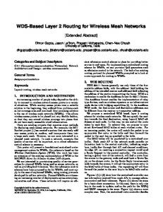


![Juniper Flow Monitoring - Juniper Networks [PDF]](https://m.moam.info/img/260x300/juniper-flow-monitoring-juniper-networks-pdf_647d073e098a9ef5168b45b0.jpg)


