Learning Capture Points for Humanoid Push Recovery John Rebula, Fabi´an Ca˜nas, Jerry Pratt
Ambarish Goswami
The Institute for Human and Machine Cognition Pensacola, FL 32502 Email:
[email protected]
Honda Research Institute Mountain View, CA 94041 Email:
[email protected]
Abstract— We present a method for learning Capture Points for humanoid push recovery. A Capture Point is a point on the ground to which the biped can step and stop without requiring another step. Being able to predict the location of such points is very useful for recovery from significant disturbances, such as after being pushed. While dynamic models can be used to compute Capture Points, model assumptions and modeling errors can lead to stepping in the wrong place, which can result in large velocity errors after stepping. We present a method for computing Capture Points by learning offsets to the Capture Points predicted by the Linear Inverted Pendulum Model, which assumes a point mass biped with constant Center of Mass height. We validate our method on a three dimensional humanoid robot simulation with 12 actuated lower body degrees of freedom, distributed mass, and articulated limbs. Using our learning approach, robustness to pushes is significantly improved as compared to using the Linear Inverted Pendulum Model without learning.
I. I NTRODUCTION Appropriate foot placement is critical when attempting to come to a stop during dynamic three dimensional bipedal walking. Simple models can be used to determine where to step in order to stop [9], [26], but the errors resulting from the assumptions of these models may be significant, especially in bipeds with a large number of degrees of freedom, distributed mass, and complex walking control systems. More complex models can reduce the errors resulting from these assumptions, but even with accurate models, small errors in modeling parameters may lead to significant errors in predicting the desired stepping location. Humans are very adept at stepping in just the right place after being pushed in order to regain balance. From simple observations of toddlers it is clear that this ability improves with practice and that learning likely plays a large role in a person’s ability to choose an appropriate place to step. This ability becomes almost reflexive as can be experienced by the following simple demonstration: Stand on one leg and have someone push you in a random direction. Notice how you step to a spot that allows you to stand on one leg again. Now, still standing on one leg, have someone push you again in a random direction, but this time purposefully step to a spot on the ground that does not allow for you to regain balance and stop. Notice how natural and automatic it seems when you step in a good spot but how difficult and how much conscious effort it takes to step in a bad spot.
Since humans are so adept at stepping to an appropriate place to recover from pushes, we argue that humanoid robots need to become just as adept at this skill in order to operate in real world environments and perform tasks that humans perform. Learning where to step in order to recover from a disturbance is a promising approach that does not require sophisticated modeling, accurate physical parameter measurements, or overly constraining limitations on the walking control system. In this paper we present a method for learning Capture Points for humanoid push recovery. Loosely speaking, a Capture Point is a point on the ground in which a biped can step to and stop without requiring another step [26], [28]. The locus of all possible Capture Points is the Capture Region. The location of the Capture Region depends on a number of factors, including the state of the robot and the kinematic reachability of the swing leg. In addition, one can define Capture Points with certain qualifications or assumptions. In this paper we assume the robot has an existing control system which can step to any reasonable desired location on the ground, and it takes this desired location as an input variable. Given the robot and control system, we learn the desired stepping location in order for the robot to stop. This method should be applicable to any humanoid robot and control system that has certain characteristics described in the next section. II. P ROBLEM S TATEMENT We wish to learn Capture Points, points on the ground that the robot can step to and stop in a single step. These Capture Points are a function of the robot’s state, the control actions during the current stance phase, and the control actions during the next stance phase in which the robot attempts to stop. In this paper we assume that the robot’s control systems already exist and that we can modify the module, which we call the Desired Stepping Location Calculator, that determines the desired stepping location. We then use learning to improve this module, better predicting Capture Points, given the preexisting control systems. Before stating the problem, we first define a few terms. Our goal is for the robot to come to a stop after being pushed. We define a Stopped State as follows: • Stopped State: Robot state in which the robot’s Center of Mass velocity, angular momentum about the Center of
Mass, and Center of Mass linear and rotational accelerations are all less than given thresholds. Note that the velocity and acceleration thresholds need to be non-zero for Stopped States to exist for many bipedal models. For example, for a point-foot point-mass biped, zero Center of Mass velocity and acceleration cannot be achieved during single support in the presence of infinitesimal disturbances. With small but finite thresholds, the robot will be essentially stopped, such that with a small amount of Center of Pressure regulation on the foot or a small amount of upper body motions, the robot could maintain balance without requiring any additional steps. For humanoids with non-point feet, given reasonable velocity and acceleration thresholds, being in a Stopped State will also imply that the Capture Region has a large intersection with the convex hull of the support feet. We consider the gait of the robot to have two main phases, the Capture Step and the Stopping Stance Phase: • Capture Step: The single support phase and swing foot placement during which the robot takes a step in attempts to reach a Stopped State during the next support phase. • Stopping Stance Phase: The support phase occurring after the Capture Step, during which the robot attempts to reach a Stopped State, without taking any additional steps. Note that the Stopping Stance Phase could be a double support phase, followed by a single support phase, or could be an instantaneous exchange of support into a single support phase. We define the control systems that are in effect during each of these two stages of the gait as follows: • Stepping Control System: The control system the robot utilizes during the Capture Step. πstep . • Stopping Control System: The control system the robot utilizes during the Stopping Stance Phase. πstop . The Stepping Control System will determine the location that the robot steps to. We define the module of this control system that determines the desired location to step to as the Desired Step Location Calculator, • Desired Step Location Calculator: Control system module of the Stepping Control System that calculates the desired step location in attempts to reach a Stopped State during the Stopping Stance Phase. Note that the Stepping Control System may query the Desired Step Location Calculator either at predefined trigger events, or continuously throughout the swing, to determine where to step to. Let us make the following assumptions: A1 The Stepping Control System is a function of the robot’s state, ~x, some internal controller state variables, p~step , and a desired stepping location, ~xstep . ~u = πstep (~x, p~step , ~xstep ). The Stepping Control System does a reasonable job of stepping to the desired step location, maintains balance, and regulates any other important aspects of walking. A2 The Stopping Control System is a function of the robot’s state, ~x, and perhaps some internal controller state variables, p~stop . ~u = πstop (~x, p~stop ). The
Stopping Control System does a reasonable job of stopping (terminating in a Stopped State), without requiring an additional step, from a reasonably sized basin of attraction of states. Our problem statement is then as follows: Given a biped with a preexisting Stepping Control System and a preexisting Stopping Control System, determine the desired foot placement for the Stepping Control System, such that after the robot takes a step, the Stopping Control System will bring the robot to a Stopped State. In other words, determine a Desired Step Location Calculator ~xstep = πcapture (~x, p~step , p~capture ), where p~capture represents potential internal state of the Desired Step Location Calculator. Note that we assume the Desired Step Location Calculator has access to both the state of the robot, ~x, and any internal state of the Stepping Controller, p~step . In this paper, we consider two implementations of the Desired Step Location Calculator: •
•
Single Decision: The Stepping Control System queries the Desired Step Location Calculator once per swing. This could occur at a trigger event, such as immediately after exchange of support, at the point of maximum body height, or just before final placement of the swing leg. In our simulation experiments, we query the step location when the Linear Inverted Pendulum Capture Point reaches a certain distance from a foot edge and a certain amount of time has been spent falling. Continuous Decision: The Stepping Control System queries the Desired Step Location Calculator every control cycle during a swing and responds smoothly to changing step locations.
In this paper we assume that a Stepping Control System and a Stopping Control System already exist for the biped and we concentrate on using learning to determine a Desired Step Location Calculator. We do this mainly because choosing an appropriate stepping location is perhaps the most critical control action to take when attempting to stop in bipedal walking, particularly in 3D bipedal walking. Other control actions, such as moving the Center of Pressure on the feet, accelerating internal momentum (e.g., lunging the upper body or “windmilling” the arms), or altering the Center of Mass trajectory are also useful control actions. However, their success depends on the robot first choosing an appropriate Desired Step Location, such that these control actions can be used to bring the robot to a Stopped State. In the experiments for this paper, the Stepping Control System and the Stopping Control System that we employ each are designed using simple physics based heuristic control rules [25]. The main strategy employed for the stopping control system is to modulate the Center of Pressure on the support foot based on a Linear Inverted Pendulum model in order to have the Center of Mass come to rest over the foot. In this paper, we do not use strategies that involve accelerating internal momentum or altering the Center of Mass trajectory based on velocity. However, controllers that use these strategies could
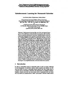
Fig. 1. Simulation results before learning (left) and after learning (right) showing the humanoid robot reacting to a disturbance in a single step. Before learning the robot fails recover balance. After learning the robot successfully comes to a stop in one step. The ball shown in the first frame of each animation applied a push from straight on at 550 Newtons for 0.05 seconds. Images are from left to right, top to bottom and are spaced 0.04 seconds apart.
also be used in the presented learning method and should result in larger Capture Regions than controllers that do not employ these strategies. We state the above problem fairly generally and would like to learn Capture Regions for any state of the robot. As a stepping stone to that result, in this paper we focus on the problem of starting in a Stopped State, being pushed, and then taking a step and returning to a Stopped State. The robot starts balancing over one leg with the other leg raised off the ground. A pushing force occurs, disrupting the robot’s balance and requiring the robot to take a step to stop. Setting the robot up like this initially is less general, but it allows us to focus on this particular instance of the problem, and allows us to generate a sufficient set of data to learn from with a reasonable number of trials. In addition, once this skill is learned, it can be used as the basis for stopping from more general conditions. III. S IMULATION M ODEL The learning method is verified on a simulated 12 degree of freedom humanoid robot. Table I details the important parameters of the model.
A. Stopping Energy Error To evaluate the performance of the learned Desired Step Location Calculator, it will be necessary to compare the errors resulting from different stepping locations. While there is a clear distinction between a Stopped State and a state that will lead to a fall, a measure of stopping error is required to compare two falling states. To compare results from stepping in different locations, we define a residual stopping “energy” as, 1 ˙ 2 1g 2 |~x| + |~x| , (1) 2 2l where ~x is the ground projection of the vector from the support foot to the Center of Mass, g is the gravitational acceleration, and l is the average Center of Mass height. Note that this quantity is similar to the conserved Orbital Energy of the Linear Inverted Pendulum Model [9], except that instead of subtracting the two terms, we add them. Estopping will decrease as the Center of Mass approaches the foot and decelerates. It will reach a minimum approximately when the Center of Mass is the closest to the foot. We use the minimum value as the Stopping Error, and refer to the state of the robot at that instance as the “top of stance” state. For a given push, it is reasonable to expect that the Stopping Error will decrease as the robot steps closer and closer to the Capture Region. When the robot steps to a Capture Point, Estopping =
TABLE I S IMULATED ROBOT PARAMETERS Total Mass Mass in Body Mass in Each Leg Leg Length Standing Center of Mass Height Foot Width Foot Length
learn from. The nominal stepping location is based on the Linear Inverted Pendulum Model [9] of walking and, in our simulations, typically predicts a Capture Point within 20 centimeters of an actual Capture Point. The off-line learning technique represents the learned Capture Point as an offset from the Linear Inverted Pendulum Capture Point. This offset is calculated based on curves fit to several variables of the state vector. The online learning technique represents the learned Capture Point in a table indexed using a simple gridding of several variables of the state space.
28.84 kg 16.0 kg 6.42 kg 0.911 m 0.945 m 0.1 m 0.203 m
IV. L EARNING T ECHNIQUES We present two different learning techniques, one off-line and one on-line, to solve the problem presented in the previous section. Instead of learning from scratch, both techniques employ a nominal stepping location as a starting point to
the Stopping Error will be near zero since the robot will pass through a Stopped State, with the Center of Mass approaching a balanced position over the foot. B. Off-line Learning Technique In the off-line learning technique, we collect data resulting from a number of different pushes on the robot, and a number of different stepping locations on the ground. The pushes were simulated as impact forces on the robot for a set time, 0.05 sec, at varying magnitudes, 150 to 550 N at 100 N intervals, yielding force impulses between 7.5 and 27.5 N sec. The direction of the applied force was varied over the full range of [0, 2π] at 10 even intervals. During learning, the Desired Step Location Calculator returned the Capture Point predicted by the Linear Inverted Pendulum Model plus an offset that varies along a 15 by 15 point grid spanning ±0.15m in both x and y. For each push setting (magnitude and direction pair), and offset, the robot is started from rest on one foot and disturbed by the impact force. The Desired Step Location Calculator decides where to step, and the simulation continues until the next support phase either reaches a Stopped State or the Center of Mass falls below 0.65m, indicating a fall. Each force setting is simulated for 225 swings, one for each offset. There are 500 force settings, yielding 112500 trials. The centroid of the Capture Region for each force setting is then calculated from the trial data. This yields an offset vector from the nominal location estimated by the Linear Inverted Pendulum Model to the centroid of the Capture Region. We learn a Desired Step Location Calculator by fitting functions of the decision state to estimate the offset vector to the centroid of the Capture Region. It was found that the angle and magnitude of the desired offset were best correlated with the angle (in the XY plane) of the Center of Mass velocity at the decision event, so this was the only dimension of the state vector used in the calculation of the offset. The learned Desired Step Location Calculator determines the desired step by calculating the Inverted Pendulum Capture Point and adding an offset vector calculated by evaluating the fit functions for the offset magnitude and angle using the decision state Center of Mass velocity angle. To test the Desired Step Location Calculator, a new set of pushes was generated at a finer resolution, 150 to 550 N at 50 N intervals and 20 even angle intervals. These pushes were simulated on the robot using both the simple Linear Inverted Pendulum model to calculate Capture Points and the learned Desired Step Location Calculator. C. On-line Learning Technique In the on-line learning technique, the robot is pushed randomly and the Desired Step Location Calculator is used to decide where to step. Based on the results of the step, the Desired Step Location Calculator is updated. The simulation is run for 10000 random pushes, with the force magnitude varying in the range of 200 to 450 Newtons, yielding force impulses between 10 and 22.5 N sec. The force direction varied in the range [− π4 , 5π 4 ]. The angle is measured from
the forward axis of the biped. We omitted the π2 radian sector to the right of the robot because the controller currently has difficulty maintaining stability in that region, and it forces the swing leg (the left leg) to cross through the support leg. 1) Gridded Capture Point Table: The Desired Step Location Calculator stores learned Capture Points in a three dimensional gridded table. The three axes of this space are the Linear Inverted Pendulum Capture Point x and y, and the distance in the XY plane of the Center of Mass from the support foot. The grid size in each of the axes is 4 centimeters. When the controller queries for a Capture Point, the Desired Step Location Calculator calculates the Linear Inverted Pendulum Capture Point, (xc,lip , yc,lip ) from the current state of the robot. It then uses (xc,lip , yc,lip ) and the distance of the Center of Mass from the support foot in the Cartesian plane to determine which grid block the current state is in. If there is a stored Capture Point in the grid block, the stored point is returned as the desired Capture Point location. If the block is empty then the point (xc,lip , yc,lip ) is returned. In the Continuous Decision implementation, the Stepping Control System applies a simple filter to the returned point each control cycle, so step changes in the desired Capture Point location as the state crosses between grid blocks are smoothed. The table begins the learning process empty. After a swing whose state passes through a grid entry with no stored value, all of the states that fell into that grid entry for the swing are recalled. The Linear Inverted Pendulum Capture Points of these states are averaged together, and the grid entry’s stored Capture Point is initialized with this value. 2) Learning Update Rule: After each swing trial, if the step location succeeded in bringing the robot to a Stopped State, no update is applied to the table. If the step location chosen resulted in the robot falling, the trial is stopped when the body height goes below 0.85 m. The final velocity vector of the body as it falls away from the support foot corresponds to the appropriate direction in which to correct the Desired Step Location. Therefore the desired offset, ~δoffset , is calculated as ~δoffset = Estopping ~x˙ f inal
(2)
where the magnitude to correct the location by is determined by Equation 1, the energy error at the top of stance. A learning gain is then applied to maintain stability of the learning process, yielding ~ = ~δoffset Klearning , ∆V
(3)
where Klearning = 0.6. For the Single Decision online learning implementation, the stored Capture Point used for the swing is updated by adding ~ to it. ∆V ~ is used to For the Continuous Decision implementation, ∆V update the stored Capture Point of each gridded state that the swing passed through, multiplied by an additional term that depends on the time that the state occurred during the swing. A sigmoidal function of time ramping from 0 at the beginning of the swing to approximately 1 halfway through the swing ~ and then added evaluated at each state is multiplied by ∆V
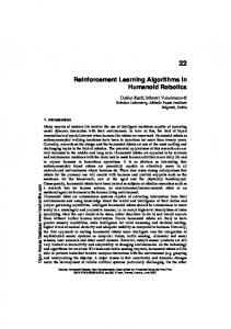
Fig. 2. Diagram showing results of stepping to various locations for a given push. Pink circles show Capture Points. At other points a red arrow shows the resulting vector from the new support foot to the Center of Mass Position and a green arrow shows the resulting Center of Mass Velocity at the point where the Center of Mass comes closest to the center of the support ankle. The black and white target shows the ground projection of the Center of Mass when the Desired Step Location Calculator was queried. The blue rectangle shows the location of the current stance foot. The center of the grid of points is the location of the predicted Capture Point using the Linear Inverted Pendulum Model.
to the stored Capture Point at that state. This time ramping factor was added because there are fewer possible states early in the swing, so they will be trained towards a larger range of Capture Points than states later in the swing. V. S IMULATION R ESULTS Learning resulted in a significant increase in the frequency of the robot coming to a stop and a significant decrease in the residual energy after a step in both the off-line learning case and the on-line learning case. A. Offline Learning Figure 2 shows the results of stepping to various locations for a given push. Pink circles show Capture Points. At other points a red arrow shows the resulting Center of Mass position and a green arrow shows the resulting Center of Mass Velocity at the point where the Center of Mass comes closest to the center of the support ankle. The black and white target shows the ground projection of the Center of Mass when the Desired Step Location Calculator was queried. The blue rectangle shows the location of the current stance foot. The center of the grid of points is the location of the predicted Capture Point using the Linear Inverted Pendulum Model. Figure 3 shows the measured and best fit stepping location offsets resulting from off-line learning. The magnitude and angle of the step location offset (vertical axes) are functions of the Center of Mass velocity angle at the decision event (horizontal axis). The offset magnitude is fit using a cubic curve. The angle is fit using a cubic curve for velocity angles less than 0, and a line for velocity angles greater than 0. Several points in each dimension were ignored as outliers when calculating the best fit curve, as the resulting fit passed near fewer of the measured points. These outliers imply that the Center of Mass velocity angle cannot completely characterize the offset vector of the Capture Point from the Linear Inverted Pendulum Capture Point. However, these curve fits provide the controller
with a simple approximation that encompasses enough of the measured data to make a reasonable prediction. Figure 4 shows the Stopping Error using Capture Points predicted from the Linear Inverted Pendulum Model and using a curve fit with off-line learning. Nine different force magnitudes from 150 to 550 Newtons for 0.05 seconds, corresponding to 7.5 to 27.5 N sec impulses were applied from 20 different directions. The mean squared error before learning is 0.137 J2 Kg 2 , and the controller successfully comes to a Stopped State only 1 out of 180 trials. After learning the mean squared error J2 is 0.0192 Kg 2 , and the controller successfully comes to a Stopped State in 45 out of 180 trials. B. On-line Learning Results Figure 5 shows the learning results of the Single Decision and Continuous Decision online learning trials. The Continuous Decision success percentage is higher both before and after learning than the Single Decision case. Before learning, this is probably due to the reactive nature of the continuously updating controller. The Single Decision Controller is limited to the initial Linear Inverted Pendulum Capture Point calculated at the beginning of the swing, whereas the Continuous Decision Controller reacts throughout the swing to an increasingly accurate Linear Inverted Pendulum Capture Point. After learning, the Continuous Decision learning also has the advantage of a higher degree of discrimination between swings because decisions made early in the swing can be refined at later grid states. Figure 6 shows a representation of the gridded memory for the Continuous Decision learning case. The three rows of the graph show the memory throughout the training process, at 1000, 2000, and 10000 iterations. The plots from left to right represent slices of the memory at progressively larger Center of Mass distances from the support foot. The Center of Mass range is represented as a black ring around the center of the foot, represented as a blue rectangle. Each point represents a gridded Linear Inverted Pendulum Capture Point, the color represents the distance from the point stored at that location to the Linear Inverted Pendulum Capture Point. As more gridded states are visited, the memory fills in new blocks, and as more states are experienced in existing blocks the stored Capture Point is refined. VI. D ISCUSSION AND F UTURE W ORK We have presented a method for learning Capture Points for humanoid push recovery. This method assumes that a Stepping Controller and a Stopping Controller already exist for the biped. We learn offsets to Capture Point locations predicted from the Linear Inverted Pendulum Model of walking. This results in a Desired Foot Placement Controller that the Stepping Controller can query. Simulation results show that this method results in significantly more robust push recovery than without using learning. There are several points of discussion and potential areas of future work.
Capture Region Center Offset Magnitude From LIP Capture Point vs COM Velocity Angle 2.2 Measured offset magnitudes 2 Measured magnitudes ignored best fit 1.8 Magnitude of offset (m)
Angle of offset vector
Capture Region Center Offset Angle From LIP Capture Point vs COM Velocity Angle 6 Measured offset angles Ignored Measured angles Best fit 5
4
3
2
1.6 1.4 1.2 1 0.8 0.6
1
0.4
0 !4
!3
!2 !1 0 1 COM velocity angle at decision time
2
0.2
3
!3
!2
!1 0 1 COM velocity angle at decision time
2
3
Fig. 3. Measured and best fit stepping location offsets resulting from off-line learning. The left graphs shows the angle of the step location offset (vertical axis) as a function of the Center of Mass velocity angle at the decision event (horizontal axis). The right graph shows the magnitude of the step location offset (vertical axis) as a function of the Center of Mass velocity angle at the decision event (horizontal axis). Stopping Error using the LIP capture point calculator vs. push angle and magnitude
1.2 1
Residual Stopping Error (J/Kg)
Residual Stopping Error (J/Kg)
Stopping Error using the Learned Function capture Point calculator vs. push angle and magnitude
0.8 0.6 0.4 0.2 0 500 400 300 200
Applied force magnitude (N)
0
1
2
3
4
5
6
1.2 1 0.8 0.6 0.4 0.2 0 500 400 300 200
Applied force angle Applied force magnitude (N)
0
1
2
3
4
5
6
Applied force angle
Fig. 4. Stopping Error using Capture Points predicted from the Linear Inverted Pendulum Model (left) and adding a Capture Point offset predicted from the simple curve fit based on the Center of Mass velocity angle at the decision event (right). Nine different force impulses were applied from 20 directions. The J2 mean squared Stopping Error when using the Linear Inverted Pendulum model is 0.137 Kg 2 , with a stopping success rate of 1 out of 180 trials. The mean squared error when using the curve fit to predict Capture Point offsets is 0.0192
J2 , Kg 2
with a success rate of 45 out of 180 trials.
Fig. 5. Results of on-line learning using the Single Decision Controller (left) and the Continuous Decision Controller (right) over 10000 training iterations. A successful trial has a value of 1, and a failed trial has a value of 0, regardless of the residual Energy Error. The points plotted represent the average value of the previous 200 trials. The filtered estimate was found by using a forward/reverse 750 trial running average of the data padded on either side with the average of the first and last 500 iterations. The vertical lines represent training being turned on at 1000 iterations and off after 11000 iterations. The disturbance forces used to test the controller before and after training are identical.
Fig. 6. A representation of the learned memory at 1000, 2000, and 10000 iterations for the continuous decision online learning case. The black ring represents the range of locations of the Center of Mass for the given graph. The blue rectangle represents the foot location. Each plotted point is a Linear Inverted Pendulum Capture Point of a gridded state. The color of the point represents the magnitude of the offset from the Linear Inverted Pendulum Capture Point to the corresponding Capture Point in memory. Blue dots represent offset magnitudes of less than 3 centimeters, dark red represents a 90 centimeter offset.
A. What was Learned? The intent of this study was to learn Capture Points for Humanoid Push Recovery. While we achieved improved push recovery performance through learning, it is interesting to think about what was really learned. While the Stepping Control System does a reasonable job of stepping to the desired step location, it does have some errors. Therefore, in addition to correcting for the deviation from the Linear Inverted Pendulum Model, we also adapt to the errors resulting from the Stepping Control System. In other words, we learned desired stepping locations that result in steps to actual Capture Points, even if the actual step is away from the desired step. B. Generalizing to More States In this study we limited the initial setup of the robot to start standing and balancing on one foot with the other foot slightly off the ground. Then a disturbance force was applied. By limiting the initial setup to these conditions, the effective size of the space that needed to be generalized over was relatively small. Since only the magnitude and direction of the disturbance push were varied between trials, only a two dimensional subspace of the full state space was visited. This limited exploration of state space allowed us to avoid the Curse of Dimensionality and easily learn Capture Point locations using standard function approximators and low dimensional state space griddings. This limited approach is justifiable as a first step toward general push recovery since the learned Capture Point locations can be used as a baseline for a broader range of state space exploration. Similarly to a toddler learning to walk, the ability to recover from a push when standing can be built on to develop the ability to recover from pushes while walking.
We are now expanding our technique to learn to recover from pushes that occur at random times during walking. This effort may require more complex learning techniques that perform good generalization over a large range of state space. However, by starting with the controller that is learned using the techniques presented in this paper, learning for the more general case should be sped up. C. Improving the Stopping Controller In this study, we used a Stopping Controller that utilizes foot Center of Pressure regulation as the main strategy for stopping the robot and balancing over the foot. Our Stopping Controller did not use acceleration of internal angular momentum (lunging the body or windmilling the arms), or modification of the Center of Mass trajectory to assist in stopping. These two neglected strategies can be quite powerful both in expanding the range of pushes that a biped can recover from and in expanding the Capture Region for a given push. We did not use these two strategies in this study simply because we do not have a good stopping controller that uses these strategies yet. We are currently developing such Stopping Controllers and have shown preliminary work for planar bipeds [26], [27]. Because we set up the problem formulation in this paper such that any reasonable stopping controller can be used, as our Stopping Controllers are improved, we should be able to use them in the current framework without requiring modification to the framework. D. Application to a Real Robot We are currently building a humanoid robot with inertial parameters that are close to the simulation model used for this paper. The robot should be operational in the Summer of 2008. The first experiments on this robot will be for humanoid push
recovery, including reproducing the results from this paper on the real robot. R EFERENCES [1] Chee Meng Chew and G.A. Pratt. Frontal plane algorithms for dynamic bipedal walking. Robotica, 22(1):29–39, 2004. [2] Chee Meng Chew and Gill A. Pratt. Dynamic bipedal walking assisted by learning. Robotica, 20(5):477–491, 2002. [3] T. Fukuda, Y. Komata, and T. Arakawa. Stabilization control of biped locomotion robot based learning with gas having self-adaptive mutation and recurrent neural networks. Proceedings of the IEEE International Conference on Robotics and Automation, pages 217–222, 1997. [4] K. Hitomi, T. Shibata, Y. Nakamura, and S. Ishii. On-line learning of a feedback controller for quasi-passive-dynamic walking by a stochastic policy gradient method. Proceedings of the IEEE/RSJ International Conference on Intelligent Robots and Systems, pages 3803–3808, 2005. [5] Andreas Hofmann. A sliding controller for bipedal balancing using integrated movement of contact and non-contact limbs. Proceedings of the IEEE/RSJ International Conference on Intelligent Robots and Systems, pages 1952–1959, 2004. [6] Andreas Hofmann. Robust Execution of Bipedal Walking Tasks From Biomechanical Principles. PhD thesis, Massachusetts Institute of Technology, 2006. [7] Sang-Ho Hyon and Gordon Cheng. Gravity compensation and fullbody balancing for humanoid robots. Proceedings of the IEEE-RAS International Conference on Humanoid Robots, pages 214–221, 2006. [8] Sang-Ho Hyon and Gordon Cheng. Disturbance rejection for biped humanoids. Proceedings of the IEEE International Conference on Robotics and Automation, pages 2668–2675, 2007. [9] S. Kajita, F. Kanehiro, K. Kaneko, K. Yokoi, and H. Hirukawa. The 3d linear inverted pendulum mode: a simple modeling for a biped walking pattern generation. Proceedings of the IEEE/RSJ International Conference on Intelligent Robots and Systems, pages 239–246, 2001. [10] Jae Won Kho, Dong Cheol Lim, and Tae Yong. Kuc. Implementation of an intelligent controller for biped walking using genetic algorithm. Proceeings of the IEEE International Symposium on Industrial Electronics, pages 49–54, 2006. [11] Jaewon Kho and Dongcheol Lim. A learning controller for repetitive gait control of biped walking robot. Proceedings of the SICE Annual Conference, pages 885–889, 2004. [12] T. Komura, H. Leung, S. Kudoh, and J. Kuffner. A feedback controller for biped humanoids that can counteract large perturbations during gait. Proceedings of the IEEE International Conference on Robotics and Automation, pages 2001–2007, 2005. [13] T.Y. Kuc, S.M. Baek, H.G. Lee, and J.O. Kim. Fourier series learning of biped walking motion. Proceedings of the 2002 IEEE International Symposium on Intelligent Control, pages 49–54, 2002. [14] Qinghua Li, Atsuo Takanishi, and Ichiro Kato. Learning control for a biped walking robot with a trunk. Proceedings of the 1993 IEEE/RSJ International Conference on Intelligent Robots and Systems., pages 1771–1777, 1993. [15] Qinghua Li, Atsuo Takanishi, and Ichiro Kato. Learning of robot biped walking with the cooperation of human. Proceedings of the IEEE International Workshop on Robot and Human Communication, pages 393–397, 1993. [16] Thijs Mandersloot, Martijn Wisse, and Christopher G. Atkeson. Controlling velocity in bipedal walking: A dynamic programming approach. Proceedings of the IEEE-RAS International Conference on Humanoid Robots, pages 124–130, 2006. [17] Yong Mao, Jiaxin Wang, Peifa Jia, Shi Li, Zhen Qiu, Le Zhang, and Zhuo Han. A reinforcement learning based dynamic walking control. Proceedings of the IEEE International Conference on Robotics and Automation, pages 3609–3614, 2007. [18] W.T. Miller. Learning dynamic balance of a biped walking robot. Proceedings of the 1994 IEEE International Conference on Neural Networks.IEEE World Congress on Computational Intelligence, pages 2771–2776, 1994. [19] T. Mori, Y. Nakamura, M. Sato, and S. Ishii. Reinforcement learning for a cpg-driven biped robot. Proceedings of the Nineteenth National Conference on Artificial Intelligence, AAAI, 2004.
[20] J. Morimoto, G. Cheng, G. Atkeson, and G. Zeglin. A simple reinforcement learning algorithm for biped locomotion. Proceedings of the IEEE International Conference on Robotics and Automation, pages 3030–3035, 2004. [21] J. Morimoto, J. Nakanishi, G. Endo, G. Cheng, C.G. Atkeson, and G. Zeglin. Poincare-map-based reinforcement learning for biped walking. Proceedings of the IEEE International Conference on Robotics and Automation, pages 2381–2386, 2005. [22] J. Morimoto, G. Zeglin, and C.G. Atkeson. Minimax differential dynamic programming: application to a biped walking robot. SICE 2003 Annual Conference, pages 2310–2315, 2003. [23] Jun Morimoto and Christopher G. Atkeson. Learning biped locomotion: Application of poincare-map-based reinforcement learning. IEEE Robotics and Automation Magazine, pages 41–51, 2007. [24] Masaki Ogino, Yutaka Katoh, Masahiro Aono, Minoru Asada, and Koh Hosoda. Vision-based reinforcement learning for humanoid behavior generation with rhythmic walking parameters. Proceedings of the IEEE/RSJ International Conference on Intelligent Robots and Systems, pages 1665–1671, 2003. [25] Jerry E. Pratt. Exploiting Inherent Robustness and Natural Dynamics in the Control of Bipedal Walking Robots. PhD thesis, Massachussetts Institute of Technology, May 2000. [26] Jerry E. Pratt, John Carff, Sergey Drakunov, and Ambarish Goswami. Capture point: A step toward humanoid push recovery. Proceedings of the IEEE-RAS International Conference on Humanoid Robots, pages 200–207, 2006. [27] Jerry E. Pratt and Sergey V. Drakunov. Derivation and application of a conserved orbital energy for the inverted pendulum bipedal walking model. Proceedings of the IEEE International Conference on Robotics and Automation, pages 4653–4660, 2007. [28] Jerry E. Pratt and Russ Tedrake. Velocity based stability margins for fast bipedal walking. In Fast Motions in Robotics and Biomechanics Optimization and Feedback Control.M.Diehl, K.D.Mombaur (editors), Lecture Notes in Information Science, Springer, No.340, Sept.2006., 2006. [29] E. Schuitema, D.G.E. Hobbelen, P.P. Jonker, M. Wisse, and J.G.D. Karssen. Using a controller based on reinforcement learning for a passive dynamic walking robot. Proceedings of the IEEE-RAS International Conference on Humanoid Robots, pages 232–237, 2005. [30] Russ Tedrake, Teresa Weirui Zhang, and H.Sebastian Seung. Stochastic policy gradient reinforcement learning on a simple 3d biped. Proceedings of the IEEE International Conference on Intelligent Robots and Systems, pages 2849–2854, 2004. [31] Shouyi Wang, Jelmer Braaksma, Robert Babuska, and Daan Hobbelen. Reinforcement learning control for biped robot walking on uneven surfaces. Proceedings of the 2006 International Joint Conference on Neural Networks, pages 4173–4178, 2006. [32] Changjiu Zhou and Qingchun Meng. Reinforcement learning with fuzzy evaluative feedback for a biped robot. Proceedings of the IEEE International Conference on Robotics and Automation, pages 3829– 3834, 2000.