Each node within the hierarchy functions as a goal-driven, model-based, ...... The GUI tool displays maps with color coding to indicate traversability cost. ..... [4] J. S. Albus and A. Meystel, Engineering of Mind: An Introduction to the Science of.
Submitted to the Journal of Field Robotics.
Learning in a Hierarchical Control System: 4D/RCS in the DARPA LAGR Program Jim Albus, Roger Bostelman, Tommy Chang, Tsai Hong, Will Shackleford, and Michael Shneier * National Institute of Standards and Technology Gaithersburg, MD 20899 {firstname.lastname}@nist.gov
Abstract The Defense Applied Research Projects Agency (DARPA) Learning Applied to Ground Vehicles (LAGR) program aims to develop algorithms for autonomous vehicle navigation that learn how to operate in complex terrain. Over many years, the National Institute of Standards and Technology (NIST) has developed a reference model control system architecture called 4D/RCS that has been applied to many kinds of robot control, including autonomous vehicle control. For the LAGR program, NIST has embedded learning into a 4D/RCS controller to enable the small robot used in the program to learn to navigate through a range of terrain types. The vehicle learns in several ways. These include learning by example, learning by experience, and learning how to optimize traversal. Learning takes place in the sensory processing, world modeling, and behavior generation parts of the control system. The 4D/RCS architecture is explained in the paper, its application to LAGR is described, and the learning algorithms are discussed. Results are shown of the performance of the NIST control system on independently-conducted tests. Further work on the system and its learning capabilities is discussed.
1. Introduction The DARPA LAGR program [1] aims to develop algorithms that will enable a robotic vehicle to travel through complex terrain without having to rely on hand-tuned algorithms that only apply in limited environments. The goal is to enable the control system of the vehicle to learn which areas are traversable and how to avoid areas that are impassable or that limit the mobility of the vehicle. To accomplish this goal, the program provided small robotic vehicles to each of the participants (Figure 1). The vehicles are used by the teams to develop software. A separate LAGR Government Team, with an identical vehicle, conducts tests of the software each month. The vehicle provided by DARPA is a small but very capable robot with substantial onboard processing capacity and a rich set of sensors. The sensors include two pairs of color cameras mounted on a turret on the front of the vehicle, a pair of infra-red range sensors (non-contact bumpers) on the front of the vehicle, and a physical bumper centered on the front wheels of the vehicle. For position sensing, the vehicle has a Global Positioning System (GPS) sensor, wheel encoders, and an inertial navigation system (INS). In addition, there are sensors for motor current, battery level, and temperature. There are four single-board computers on the vehicle, one for low-level vehicle control, one for each of the stereo camera pairs, and one for overall control of the vehicle. All processors use the Linux operating system. The vehicle has an internal Ethernet network connecting the processors, and a wireless Ethernet link to external processors.
*
Corresponding author.
1
Figure 1. The small robot used in the DARPA LAGR program.
The availability of range information from stereo vision enables the robot to navigate largely using the geometry of the scene. Another viable approach is to use the topology of the surrounding space [2]. We chose to use a geometric approach, although both are compatible with the 4D/RCS architecture. Sensor processing is aimed at determining where the vehicle is and what parts of the world around it are traversable. The robot can then plan a path over the traversable region to get to its goal. A typical range sensor will not be able to provide reliable range very far in front of the vehicle, and it is part of the aim of this work to extend the traversability analysis beyond the range sensing limit. This is done by associating traversability with appearance, under the assumption that regions that look similar will have similar traversability. Because there is no direct relationship between traversability and appearance, the system must learn the correspondence from examples and from experience. One of the expectations in the LAGR program is that the vehicle will learn to do without stereo vision at times, so it must learn to distinguish traversable terrain from nontraversable terrain based on other sensor inputs. The main sensors we use to do this are the color cameras (monocular) and the bumper sensors. We also use the position sensors to tell if we are traversing terrain we have previously driven over, in which case we may have a map, or a remembered path, or a traversability model. Further, if we are traversing terrain that has already been modeled, we use the fact that the vehicle is able to cross a region to modify the traversability models for this terrain. Similarly, if the bumpers hit an object, this fact is remembered in maps and in traversability models. The NIST team took the approach of building a control system for the vehicle based on the 4D/RCS (Four Dimensional/Real-Time Control System) architecture [3,4]. 4D/RCS is a version of the NIST RCS reference control system architecture that is specially oriented towards robotic vehicles. It is described in Section 2, while the operator interface is described in Section 6. For the LAGR program, the team is embedding learning modules into the control architecture. The team has developed learning algorithms for the sensory processing (Section 3.1), world modeling (Section 4), and behavior generation (Section 5) parts of the control system. The sensory processing algorithms try to learn from camera images the appearance of regions that are safe to traverse (which we call ground regions) and those that are not traversable (obstacles). More precisely, the algorithms pro2
vide an estimate of the cost of traversing a region rather than a single label of obstacle or ground. The world modeling modules remember maps of known regions with their associated traversabilities, while for behavior generation the system remembers paths taken when previously traversing a region. It can then optimize paths through these regions by avoiding regions with poor traversability and control the speed of the vehicle based on its knowledge of the local traversability. Learning has been applied to computer vision for a variety of applications, including traversability prediction. Wellington and Stentz [5] predicted the load-bearing surface under vegetation by extracting features from range data and associating them with the actual surface height measured when the vehicle drove over the corresponding terrain. The system learned a mapping from terrain features to surface height using a technique called locally weighted regression. Learning was done in a map domain. We also use a map in the current work, although it is a two dimensional (2D) rather than a three dimensional (3D) map, and we also make use of the information gained when driving over terrain to update traversability estimates, although not as the primary source of traversability information. The models we construct are not based on range information, however, since this would prevent the extrapolation of the traversability prediction to regions where range is not available. Howard et al. [6] presented a learning approach to determining terrain traversability based on fuzzy logic. A human expert was used to train a fuzzy terrain classifier based on terrain roughness and slope measures computed from stereo imagery. The fuzzy logic approach was also adopted by Shirkhodaie et al. [7], who applied a set of texture measures to windows of an image followed by a fuzzy classifier and region growing to locate traversable parts of the image. The problem faced by a robot of finding a path to a goal point is a feedback control problem. The sensed feedback information comes from the cameras, Global Positioning System (GPS), etc. The actuators are the drive motors on the wheels. The on-board computer implements the feedback controller that drives the vehicle position (part of the state) to the goal position. It is for this reason that there are similarities between learning methods for robots and the field of adaptive control (sometimes called learning control). The closest relationships are to the area of “on-line approximation based feedback control” [8], and in particular the “indirect adaptive control strategy” where a parameterized nonlinear map (e.g., implemented by a fuzzy or neural system) is adjusted to represent the process (environment) and then control decisions are based on that map. Stability, convergence, and robustness analysis is conducted for such feedback systems and principles of operation offer insights into the design of navigation methods for learning robots (e.g., the use of the notion of “probing” the environment vs. making progress toward reaching the goal, one of the most central ideas in adaptive control). Moreover, extended notions of adaptive control use learned models for planning and route selection by marrying ideas in adaptive and “model predictive control” [9]. Indeed, the map-based strategy here is an excellent example of how successful such approaches can be.
3
The notions of learning we use in this paper arose in the field of psychology. First, the most basic low levels of learning represented by the notions of “habituation” and “sensitization” [10] are embedded in our algorithms. If the robot learns via multiple sensor inputs that an area is traversable, then it has been habituated to that input (it has learned to ignore information and go ahead and travel in a direction). Correspondingly, if the robot has learned that some sensory inputs correspond to a lack of traversability, then if such situations are encountered again the robot is sensitized and hence may not make the same attempts to travel through nontraversable areas as it did in the past. Such learning in the form of habituation and sensitization sets the foundation for the elements of “classical and operant conditioning” [10] that occur in our robot. Our cell update strategies correspond to learning strategies where via repeated sensory inputs it can learn to associate sensed features with a lack of traversability or good traversability so that the basics of classical conditioning are present. Indeed, our robot can exhibit the property of “blocking” since in learning it can initially use some sensed information to determine traversability, and then later when there are other learning opportunities, it will at times ignore new sensory information (model updates) since it is confident that for instance more sensory verification of the model is not needed. With respect to the “behaviorist” approach to operant conditioning, if the robot senses some scene and it has learned that certain features are associated with rewards (getting closer to the goal by making forward progress), it will try to apply the same actions that were successful before, leading to the “Thorndike’s effect” similar to what occurs in a “Skinner box” [10]. And, such opportunities for conditioning can occur during a single attempt by the robot to find a goal point via storage, updating, and later use of information in our maps as the robot travels. Moreover, our learned maps can be used between trials so that on successive attempts the robot learns how to direct its behavior to succeed even faster; hence, a basic property of “speed-up” in the rate of reward acquisition seen experimentally in rats in mazes [10] can also be exhibited by our system. Finally, we note that our use of maps is quite similar to the idea that animals and humans build (learn) and use “cognitive maps” of their environment for planning spatial movement ([11]; [12]; [13]).
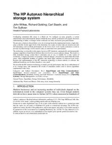
2. The 4D/RCS architecture The 4D/RCS architecture specifies a multi-resolution hierarchy containing multiple levels of generic computational nodes[3,4]. Each node contains sensory processing (SP), world modeling (WM), value judgment (VG), and behavior generation (BG) modules, as well as a knowledge database (Figure 2). Commands come in to each node from a higher level in the hierarchy, usually in the form of actions to be taken. These actions are broken down into a list of sub-actions by the behavior generation module, based on its interactions with the world model, value-judgment and, indirectly, sensory processing modules. The sub-actions are passed down to the next lowest level. At the bottom of the hierarchy, the BG modules operate actuators that cause changes in the real world. Information also passes up the hierarchy, usually in the form of status information for behavior generation, and in the form of partially processed sensory data for sensory processing and summarized map information for world modeling.
4
Each node within the hierarchy functions as a goal-driven, model-based, closed-loop controller. It is capable of accepting and decomposing task commands into actions that accomplish task goals despite unexpected conditions and dynamic perturbations in the world. At the heart of the control loop through each node is a rich, dynamic world model that provides the node with an internal model of the external world (Figure 3). In each node, the world model provides a site for data fusion, acts as a buffer between perception and behavior, and supports both sensory processing and behavior generation. SENSORY OUTPUT
STATUS
RCS Node
VALUE JUDGMENT
PERCEIVED OBJECTS & EVENTS
PLAN
UPDATE
SENSORY PROCESSING
PREDICTED INPUT OBSERVED INPUT
WORLD MODELING
OPERATOR INTERFACE
EV PL AL AN UA TI ON
PLAN RESULTS
SITUATION EVALUATION
PEER INPUT OUTPUT
COMMANDED TASK (GOAL)
BEHAVIOR GENERATION
STATE
KNOWLEDGE DATABASE To Higher and Lower Level World Modeling
SENSORY INPUT
STATUS
COMMANDED ACTIONS (SUBGOALS)
Figure 2. Internal structure of a 4D/RCS NODE. Mission Goal
Perception
World Model
Behavior
internal external
Sensing
Real World
Action
Figure 3. The fundamental structure of a 4D/RCS control loop.
In support of behavior generation, the world model provides knowledge of the environment with a range and resolution in space and time that is appropriate to task decomposition and control decisions that are the responsibility of that node. The world model also provides simulation and modeling for planning and reasoning about the future. This enables behavior generation to plan and control actions that are most likely to achieve the given goal at minimum cost and maximum benefit. In support of sensory processing, the world model provides predictions that can be matched with observations for recursive estimation and Kalman filtering. The world model can also provide hypotheses for gestalt grouping and segmentation. Thus, each node in the 4D/RCS hierarchy is an intelligent system that accepts goals from above and generates commands for subordinates so as to achieve those goals. 5
The centrality of the world model to each control loop is a principal distinguishing feature between 4D/RCS and behaviorist (i.e., purely reactive) architectures [14,15]. Behaviorist architectures rely solely on sensory feedback from the world. They do not fuse information from multiple sensors over time, nor do they integrate sensory feedback with a priori knowledge. All behavior is a reaction to immediate sensory feedback. In contrast, the 4D/RCS world model integrates all available knowledge into an internal representation that is far richer and more complete than is available from immediate sensory feedback alone. This enables more sophisticated behavior than can be achieved from purely reactive systems. The character and structure of the world model also distinguishes 4D/RCS from conventional artificial intelligence (AI) architectures. Most AI world models are purely symbolic. In 4D/RCS, the world model is much more than a symbolic abstraction of the world. It is, rather, a combination of instantaneous signal values from sensors, state variables, images, and maps that are linked to symbolic representations of entities, events, objects, classes, situations, and relationships in a composite of immediate experience, short-term memory, and long-term memory. Real-time performance in modeling and planning is achieved by restricting the range and resolution of maps and data structures to what is required by the behavior generation module at each level. Short range and high resolution maps are implemented in the lowest level, with longer range and lower resolution maps at the higher level. Sensory processing modules pass information up the hierarchy, starting at the bottom with input from the sensors. At each level, more and more complex processing is done, and higher and higher levels of grouping and classification are carried out. The world model at each level serves as a buffer between sensory processing and behavior generation, fuses and manages information coming in from the sensory processing and behavior generation modules, and keeps the internal model of the world up to date. Mission (Goal) SENSORY PROCESSING Classification Estimation Computation Grouping Windowing
WORLD MODELING VALUE JUDGMENT KNOWLEDGE
BEHAVIOR GENERATION
Maps
Entities
Task Knowledge
Images
Events
Planners Executors
internal external Sensors
World
Actuators
Figure 4. The basic internal structure of a 4D/RCS control loop.
At every level, events are detected, objects recognized, situations analyzed, and status reported to superiors at the next higher level. The world model at each level enables the 6
intelligent system to analyze the past, plan for the future, and perceive sensory information in the context of expectations. A set of cost functions enable value judgments and determine priorities that support intelligent decision making, planning, and situation analysis. This provides a robust form of value driven behavior that can function effectively in an environment filled with uncertainties and unpredictable events. At the lower levels of the hierarchy, closer to the real world on which the system acts, modules operate with short update rates on small distances at high resolution. This enables high precision and quick response to be achieved over short intervals of time and space. At each successively higher level, range in space and time increase by about an order of magnitude, accompanied by an order of magnitude decrease in resolution. 4D/RCS is a hybrid architecture, with both deliberative (reasoning and planning) and reactive (rapid response to exigencies) capabilities. Each level of the control hierarchy includes deliberative planning processes that receive goals and priorities from superiors and decompose them into subgoals and priorities for subordinates at levels below. Each level also has reactive loops that respond quickly to feedback to modify planned actions so that goals are accomplished despite unexpected events. Thus, planning and decision making are distributed throughout the hierarchy. At every level, plans are formulated, decisions are made, and reactive actions are taken locally by the units that are most affected and best able to analyze the situation and respond effectively. For the LAGR program, a two-level hierarchy is being implemented (Figure 5). This has been all that is necessary for the small size of the LAGR test courses (typically about 100 m on a side) and the relatively short duration of the test missions (typically less than 4 minutes). In the second phase of the LAGR program, the small robot will be replaced with a much larger vehicle (the Spinner vehicle). For this vehicle, additional levels of the hierarchy will need to be added, especially if the complexity of the missions is increased. In a typical 4D/RCS system, there would be a level below the lowest LAGR level implemented, which would directly interface with the sensors and actuators. The lowest level actuators and sensors are not, however, directly available to the 4D/RCS system in the LAGR vehicle implementation, but must be accessed through an interface provided by the system. Thus, the lowest 4D/RCS level sends commands to this interface and receives status from the interface instead of communicating directly with the hardware on the system. The modules of the system will be described in the next section. We conclude this section with an overview of the way that communications are implemented.
2.1. Inter-Process Communication A very rich interconnection is established between modules at each level and across levels in the hierarchy (Figure 2). In practice, levels and modules can be scattered across multiple processors on multiple systems, perhaps with different operating systems, programming languages, and hardware architectures. The physical links can range from shared memory to wide-area networks. All the complexities of inter-process communications are hidden from the 4D/RCS implementation through system-wide use of the Neutral Messaging Language (NML) [16]. Extensive documentation and complete source code for both NML and RCS (the architecture underlying 4D/RCS) are available at [17].
7
commands SP2
images name class
Classify objects Group pixels
SP1
images color range edges class Classify pixels
Compute attributes Scale & filter
WM2
BG2
Manage KD2
Planner2 frames names attributes state class relations
maps cost objects terrain 200x200 pix 400x400 m
10 step plan Executor2
status
WM1
commands
BG1 Manage KD1
state variables names values
maps cost terrain 200x200 pix 40x40 m
Planner1 10 step plan Executor1
commands
signals Sensors Cameras, INS, GPS, bumper, encoders, current
Actuators Wheel motors, camera controls
Figure 5. Two-level instantition of the 4D/RCS hierarchy for LAGR. For clarity, not all the interactions are shown.
NML provides a uniform way of sending information between processes. It implements an Application Programmer’s Interface (API) to communication functions that include many popular protocols: intra-process shared memory; inter-processor backplane global memory; and Internet networking. NML implements a mailbox model for communication, with both queued- and non-queued access, blocking- and non-blocking reads and writes, and multiple readers and writers. NML provides language bindings for C++ and Java. The protocol parameters are contained in configuration files that are read at run time, so that a system’s allocation of processes to processors can be deferred as late as desired and modified dynamically. NML handles mutual exclusion for data integrity, and converts between native machine format and neutral data encoding when necessary. The sender and receiver of an NML message need to agree ahead of time on the format of the message and what behavior should result from its transmission. There is no restriction on what messages can mean, but typically they contain commands, status, sensory processing data, or world model information. Messages typically range in size from a few bytes to hundreds of kilobytes, and can be of fixed or variable length. There is no limit to message size other than practical memory limits. A valuable advantage of this messaging approach to communication is that an operator can have access to all the message buffers to either monitor what is happening in the system or to modify it by inserting information into one or more buffers. The operator control interface described in Section 26 makes extensive use of this capability.
8
3. 4D/RCS Mapped to LAGR We describe the modules that have been implemented in the two-level 4D/RCS hierarchy that controls the LAGR vehicle. These include two levels each of sensory processing, world modeling, and behavior generation. The value judgment modules have not been independently implemented; their functionality is shared between the world model and behavior generation modules. We also describe the operator control interface developed to monitor and control the system. Example output of the sensory processing and map building are shown both in the relevant sections and in the description of the operator control unit. All examples are taken from log files of runs of the system by the LAGR Government Team.
3.1. Sensory Processing The sensor processing column in the 4D/RCS hierarchy for LAGR will be described from the bottom up. It starts with the sensors. Those used in the sensory processing module include the two pairs of stereo color cameras, the physical bumper and infra-red bumper sensors, the motor current sensor (for terrain resistance), and the navigation sensors (GPS, wheel encoder, and INS). Sensory processing modules include a stereo obstacle detection module, a bumper obstacle detection module, an infrared obstacle detection module, an image classification module, and a terrain slipperyness detection module. We describe only those components that are important for learning.
3.1.1.
Stereo Vision
Stereo vision is primarily used for detecting obstacles, while the individual color camera data are used for classification and learning. Stereo processing takes place in the lowest SP level, SP1. We use the very efficient SRI Stereo Vision Engine [18] to process pairs of images from the two stereo camera pairs. This algorithm computes rectification to remove distortion from images and extracts features by computing the Laplacian of Gaussian for each image. Next, correlation computes disparities by matching. Uncertain matches are removed in a filtering stage, and finally disparities are converted to 3D points. The 3D points are associated with registered color data and pixel locations in the reference image.
9
6
7
5 4 0
1
2
3
0
1
2
3
4
5
6
7 8
8
9
9
Figure 6. A single vertical scanline detecting the ground. Pixel 0 corresponds to the elevation of the vehicle’s wheels. Pixels 1, 2, 3, 8 and 9 are ground pixels due to shallow slopes. Pixel 4, 5, 6 and 7 are obstacles due to steeper slopes. The slopes are shown by the direction vectors on the bottom of the figure
Obstacles are defined as objects that project more than some distance d above or below the ground. Positive obstacles are detected in the range images, while negative obstacles are detected in the world model map [19]. The algorithm scans column by column in the image, starting with a point known to be on the ground. An initial ground value is assigned at the location where the front wheels of the vehicle touch the ground, known from Inertial Navigational System (INS) and GPS sensors. A pixel is labeled a positive obstacle if it rises high enough and abruptly enough from the ground plane (Figure 6). The negative obstacle detection algorithm maintains its own high-resolution ground map centered on the vehicle. This ground map contains all the projected ground pixels detected by the positive obstacle detection module. The algorithm first identifies the pixels in the range image that potentially correspond to a negative obstacle because they are below the ground level and are large enough. For efficiency, the algorithm detects only the borders of negative obstacles. For each newly acquired stereo image pair, the obstacle detection algorithm processes each vertical scan line in the reference image independently and classifies each pixel. Pixels that are not in the 3D point cloud (places where the stereo algorithm failed) are marked INVALID. Pixels corresponding to obstacles that are shorter than 5 cm high are marked as SHORT_OBSTACLE. The obstacle height threshold value of 5 cm was chosen such that the LAGR vehicle can ignore and drive over small pebbles and rocks. Similarly, COVER corresponds to obstacles that are taller than 1.5 m, a safe clearance height for the LAGR vehicle.
10
Figure 7. Operator Control Unit Displays showing right and left: original color images (top), results of obstacle detection (middle), and cost maps (bottom). Cost values are converted to colors for visualization purpose. Red corresponds to obstacles, green to ground, and blue to regions so far away the confidence in the stereo output is too low for processing.
Within each reference image, the corresponding 3D points are accumulated onto a 2D cost map of 20 cm by 20 cm cell resolution. Each cell has a cost value representing the percentage of OBSTACLE pixels in the cell. The output of the stereo obstacle detection is sent to the world model (WM1 and WM2) and to the second level of sensory processing (SP2). Figure 7 illustrates obstacle detection with an image captured while the vehicle was driving on a dirt road lined with trees and with an orange fence across the road ahead. The top row shows images from one of the left and one of the right stereo pair of cameras. The second row of the display shows an overlay of the obstacle detection results on the image. In this image, green is used to show ground points, red for obstacles, and blue for regions that were not processed, because the were too far away for the stereo algorithm to provide reliable range information. The bottom row shows an overhead view of the results of the processing for each of the eyes.
3.1.2.
Learning Color Models for Classification
A color-based image classification module runs independently from the obstacle detection module in SP1. It learns to classify objects in the scene by their color and appearance. This enables it to provide information about obstacles and ground points even when stereo is not available. A flat world assumption is used when determining the 3D location of a pixel in the image. This assumption is valid for points close to the vehicle providing that the vehicle does not get too close to an obstacle. 11
In [20] Ulrich and Nourbakhsh also addressed the issue of appearance-based obstacle detection using a color camera and no range information. Their approach makes the same assumptions that the ground is flat and that the region directly in front of the robot is ground. This region is characterized by Hue and Saturation histograms and used as a model for ground. The authors used the motion of the robot to determine if the ground region was free of obstacles by saving the histograms of trapezoidal regions in the image associated with positions. When the vehicle moved over a region, the region became known to be empty, and the associated histograms were merged with the model. In another learning method, to be discussed in Section 3.2, information about traveling over a region is used in a different way to learn traversability. Ulrich and Nourbakhsh do not model the background, and have only a single ground model (although they observe that more complex environments would call for multiple ground models). Their work was applied to more homogeneous environments than ours, and we found that multiple models of ground are essential for good performance in the kinds of terrain used to test the LAGR vehicles. Our algorithm segments an image of a region by building color models similar to those proposed by Tan et. al. [21], who applied the approach to road following. For off-road driving, the algorithm was modified to segment an image into traversable and nontraversable regions. Color models are created for each region based on two-dimensional histograms of the colors in selected regions of the image. Previous approaches to color modeling have often made use of Gaussian mixture models. However, this approach assumes Gaussian color distributions. Our experiments have shown this assumption to be false. A superior method is to make use of color histograms. In addition, many road detection systems have simply made use of the RGB color space in their methods. However, previous research (He et al., [22], Kristensen, [23], Lin and Chen,[24]) has shown that other color spaces may offer advantages in terms of robustness against changes in illumination, which should prove useful in the real world environment. It was found that a 30 x 30 histogram of red (R) and green (G) gives the best results in the LAGR environment. The approach makes the assumption that the area in front of the vehicle is safe to traverse That is, it can be classified as ground. A trapezoidal region at the bottom of the image (i.e., in front of the vehicle) is assumed to be ground (Figure 8). A color histogram is constructed for the points in this region to create the initial ground model. The trapezoidal region is the projection of a 1 m wide by 2 m long area in front of the vehicle under the assumption that the vehicle is on a plane defined by its current pose. Multiple color models are learned for road regions, as discussed below. Construction of the background model initially randomly samples pixels in the area above the horizon, assuming that they represent non-traversable regions. Because this area might only contain sky pixels, we extend the sampling area to 50 pixels below the horizon. Once the algorithm is running, the algorithm randomly samples pixels in the current frame that the previous result identified as background. This enables the background regions to expand below the horizon. These samples are used to update the background
12
color model using temporal fusion. Only one background model is constructed since there is no need to distinguish one type of background from another. To enable the vehicle to remember traversable terrain with different color characteristics, multiple ground color models are learned. As new data are processed, each color distribution model is updated with new histograms, changing with time to fit changing conditions. Potential new histograms for representing ground are compared to existing models. If the difference is less than a threshold, the histogram is used to upgrade the best matching ground model. Otherwise, if a maximum number of ground models has not yet been reached, the algorithm enters a period known as learning mode. Learning mode is a period of time in which the algorithm monitors new histograms in an attempt to pick out the histogram that is most different from the existing ground models. This is done to avoid picking color models that contain significant amounts of overlap. In the learning mode, if a histogram is found to be more different than a previous histogram, learning mode is extended. Eventually learning mode will end, and the most different histogram is used to create a new color model. Learning mode is turned off when the region assumed to be ground contains obstacles. This is determined by projecting obstacles in the world model map into the image. It is also disabled if the LAGR vehicle is turning faster than 10 degrees per second or if the LAGR vehicle is not moving. The algorithm can also read in a priori models of certain features that commonly appear in the LAGR tests. These include models for a path covered in mulch, a path covered in white lime (Figure 8b), and an orange obstacle (to deal with orange plastic fences such as that seen in Figure 7. Figure 8 shows two examples of the output of the color model based classifier. Figure 8a shows a view on an unpaved road, while Figure 8b shows a path laid down in a field that the vehicle is supposed to follow. Note that in all the display of images from the color stereo cameras the output from the right camera is shown on the left because the right camera looks to the left so that the images it captures are of the left field of view of the vehicle. Similarly, the left camera looks to the right. The display thus shows the vehicle’s field of view in a natural way.
13
(a)
(b)
Figure 8. a. Top: the original color images, with the classification images based on the histogram color model shown underneath. Green means ground, the other colors are background regions with higher traversability costs. b. Another scene showing clearly the algorithm’s ability to learn to associate traversability with a distinctively-colored path.
Given the models, the algorithm goes through every pixel in an image and calculates a ground probability based upon its color. The end result is a probability map that represents the likelihood that an area is ground. Given the pixel’s color, a ground color model and the model for background, ground probability is calculated as: N ground Pground = N ground + N background where N ground is the count in the ground histogram bin indexed by the pixel, N background is the count in the background histogram bin indexed by the pixel, and Pground is the probability that the pixel is a ground pixel. When there are multiple ground models, all are matched and the largest ground probability is selected. Multiple ground probabilities are calculated at each pixel. The largest ground probability is selected as the ground probability for that pixel. A further step applied to the ground histograms is temporal fusion. This combines ground probabilities across multiple image frames to improve stability and reduce noise. The temporal fusion algorithm can be described as a running average with a parameter to adjust for the influence of new data. The update equation is:
14
( w × Pt −1 ) + ( c × P ) ( w + c) w = w + c if w < wmax Pt =
Where P is the current probability that the pixel should be labeled ground, Pt −1 is the probability that the same pixel was labeled ground in the previous frame, Pt is the ground probability of temporal fusion of the pixel. And w and c are the weighting constants. Wmax is the maximum number of images used for temporal fusion. The final probability map is used to determine the traversability cost at each pixel as
Cost = (1 − Pt ) * 250 Costs run from 0 being most traversable to 250 being least traversable. In order to reduce processing requirements, probabilities are calculated on a reduced version of the original image. The original image is resized down to 128 x 96 through an averaging filter. This step has the additional benefit of noise reduction. Experimentation shows that this step does not significantly impact the final segmentation. A noteworthy aspect of this algorithm is that the color models are constructed from the original image for better accuracy, whereas probabilities are calculated on a reduced version of the image for greater speed. The cost of each pixel in the image is sent to the world model with a 3D location determined using the assumption of a flat ground plane.
3.2. Learning Traversability Models from Color and Range Another model-based learning process occurs in the SP2 module of the 4D/RCS architecture, taking input from SP1 in the form of labeled pixels with associated (x, y, z) positions as described in Section 3.1.1. This process learns color and texture models of traversable and non-traversable regions, which are used in SP1 for terrain classification. Thus, there is two-way communication between the levels, with labeled 3D data passing up, and models passing down. The approach to model building is to make use of the labeled data including range, color, and position to describe regions in the environment around the vehicle and to associate a cost of traversing each region with its description. Models of the terrain are learned using an unsupervised scheme that makes use of both geometric and appearance information. The appearance of regions in an image has been described in many ways, but most frequently in terms of color and/or texture. Ulrich and Nourbakhsh [25] used color imagery to learn the appearance of a set of locations to enable a robot to recognize where it is. A set of images was recorded at each location and served as descriptors for that location. Images were represented by a set of one-dimensional histograms in both HLS (hue, luminance, saturation) and normalized Red, Green, and Blue (RGB) color spaces. When the robot needed to recognize its location, it compared its current image with the set of images associated with locations. To compare histograms when matching images, the Jef-
15
frey divergence was used. The location was recognized as that associated with the bestmatching stored image. An assumption is made that terrain regions that look similar will have similar traversability. The learning works as follows [26]. The system constructs a map of a 40 m by 40 m region of terrain surrounding the vehicle, with map cells of size 0.2 m by 0.2 m and the vehicle in the center of the map. The map is always oriented with one axis pointing north and the other east. The map scrolls under the vehicle as the vehicle moves, and cells that scroll off the end of the map are forgotten. Cells that move onto the map are cleared and made ready for new information. The model-building algorithm takes as input from SP1 the color image, the associated and registered range data (x, y, z points), and the labels (GROUND and OBSTACLE) computed by the obstacle-detection step. Also associated with these data is the location and pose of the vehicle when the data were collected. The process works as follows: When new data are received from SP1, the pose and location information are used to scroll the map so that the vehicle occupies the center cell of the map. Each point of the incoming data is processed as follows: 1. If the vehicle is turning too fast or is stationary, learning is disabled. 2. If the point is not labeled as GROUND or OBSTACLE, it is skipped. Points that do not have associated range values are also skipped. 3. Points that pass step 1 and 2 are projected into the map using the x, y, and z values of the point and the pose of the vehicle. If a point projects outside the map it is skipped. Each cell receives all points that fall within the square region in the world determined by the location of the cell, regardless of the height of the point above the ground. The cell to which the point projects accumulates information that summarizes the characteristics of all points seen by this cell. This includes color, texture, and contrast properties of the projected points, as well as the number of OBSTACLE and GROUND points that have projected into the cell. Color is represented by ratios R/G, R/B, and G/B rather than directly using R, G, and B. This provides a small amount of protection from the color of ambient illumination. Each color ratio is represented by an 8-bin histogram. Intensity is also computed and stored in an 8-bin histogram. All histogram values are stored in a normalized form so that they can be viewed as probabilities of the occurrence of each ratio. Texture and contrast are computed using Local Binary Patterns (LBP) [27]. These patterns represent the relationships between pixels in a 3x3 neighborhood in the image, and their values range from 0 to 255. The texture measure is represented by a histogram with 8 bins, also normalized. Contrast is represented by a single number ranging from 0 to 1.
16
4. When a cell accumulates enough points it is ready to be considered as a model. In order to build a model, we require that 95% of the points projected into a cell have the same label (OBSTACLE or GROUND). If a cell is the first to accumulate enough points, its values are copied to instantiate the first model. Models have exactly the same structure as cells, so this is trivial. If there are already defined models, the cell is matched to the existing models to see if it can be merged or if a new model must be created. Matching is done by computing a weighted sum of the squared difference of the elements of the model and the cell. Cells that are similar enough are merged into existing models; otherwise, new models are constructed. 5. At this stage, there is a set of models representing regions whose appearance in the color images is distinct (Figure 9). Our interest is not so much in the appearance of the models, but in the traversability of the regions associated with them. Traversability is computed from a count of the number of GROUND and OBSTACLE points that have been projected into each cell, and accumulated into the model. Models are given traversability values computed as N OBSTACLE /( N GROUND + N OBSTACLE ) . When all the points in the input data have been processed, the traversability map is sent to the World Model (WM1 and WM2) as follows. Only cells that have values that have changed are sent. If a cell does not have an associated model, its local traversability measure is sent. If it does have a model, the traversability computed from the model is sent. This means that information learned in one region is propagated to other, similar regions. The WM has no knowledge of the local models, and receives only traversability information rather than region identity. The models are built as a kind of learning by example. The obstacle detection module identifies regions by height as either obstacles or ground. Models associate color and texture information with these labels, and use these examples to classify newly-seen regions. Another kind of learning is also used to measure traversability. This is especially useful in cases where the obstacle detection reports a region to be of one class when it is actually of another, such as when the system sees tall grass that looks like an obstacle but is traversable, perhaps with a greater cost than clear ground. This second kind of learning is learning by experience: Observing what actually happens when the vehicle traverses different kinds of terrain. The vehicle itself occupies a region of space that maps into some neighborhood of cells in the traversability cost map. These cells and their associated models are given an increased traversability weight because the vehicle is traversing them. If the bumper on the vehicle is triggered, the cell that corresponds to the bumper location and its model, if any, are given a decreased traversability weight. We plan to further modify the traversability weights by observing when the wheels on the vehicle slip or the motor has to work harder to traverse a cell. The color model used to represent the appearance of the terrain models is a descendent of the histogram intersection approach developed by Swain and Ballard [28]. Instead of three-dimensional histograms, we use three one-dimensional histograms, and instead of their histogram intersection algorithm for comparing histograms, we use a sum of
17
squared difference measure (which is very similar to the sum of absolute differences used in histogram intersection). The size of the histograms we use is substantially smaller also, but, as expected from Swain and Ballard’s analysis, this has little impact on the accuracy of the matching. Pietikainen et al. [29] showed that three one-dimensional histograms perform almost as well as one three-dimensional histogram, although they did not use color ratio histograms in their experiments.
R/G
R/ B
G/ B
LBP
R/G
R/ B
G/B
LBP
R/G
R/ B
G/B
LBP
Figure 9. Histograms representing three different models. Models include other elements, such as intensity, contrast and traversability.
Figure 10 shows a set of views from the vehicles Operator Control Unit during learning and classification. Figure 10a shows the points selected for learning models. The top of the Figure shows camera views from one of each of the stereo camera pairs. The bottom shows an overlay of the learned points. Points displayed in green correspond to ground, while those in red correspond to obstacles. Note that models for the left and right stereo pairs are learned independently. For subsequent runs, the system provides the option for combining the learned models from each eye (the usual case) or for keeping the models separate.
18
3.3. Using the Models to Classify Images The models are used in the lower sensory processing module, SP1, to classify image regions and assign traversability costs to them. For this process only color information is available, with the traversability being inferred from that stored in the models. The approach is to pass a window over the image and to compute the same color and texture measures at each window location as are used in model construction. Matching between the windows and the models operates exactly as it does when a cell is matched to a model in the learning stage. Windows do not have to be large, however. They can be as small as a single pixel and the matching will still determine the closest model, although with low confidence. In the implementation the window size is a parameter, typically set to 16x16. If the best match has an acceptable score, the window is labeled with the matching model. If not, the window is not classified. Windows that match with models inherit the traversability measure associated with the model. In this way large portions of the image are classified. When the stereo module is working, the main use of the classifier is to assign traversability to regions beyond the range of stereo. Thus, a window in the image is processed starting at the end of good stereo and ending a little above the horizon (obstacles are expected to rise above the horizon). When stereo is not available, the whole image is processed to provide traversable and non-traversable regions for navigation. It is possible to classify the entire image while stereo is operating, but this is seldom done because of the computational cost of running both processes in the same processor. Figure 10b shows an example of the long-range classification done during learning with stereo. Yellow regions indicate those classified as traversable, while magenta regions are non-traversable. Figure 10c shows an example of classification from the learned models when stereo is not available. Note that while only two colors are used in the Figures, traversability cost is computed as a number between 0 and 250, with lower numbers meaning greater traversability.
(a)
(b)
(c)
Figure 10. (a) Points selected for learning. Green indicates ground points, red indicates obstacle points. (b) Classification in the region beyond stereo. Yellow indicates traversable, magenta nontraversable. (c). Classification of the ground out to the horizon.
A problem arises in sending the results to the World Model, which requires a 3D location to be associated with each point. As in Section 3.1.2, we make the assumption that the 19
ground is flat, i.e., that the pose of the vehicle defines a ground plane through the wheels. This allows windows that match with models to be mapped to 3D locations. Another assumption is that all obstacle windows (matching with models created from obstacle points) are normal to the ground plane. This allows obstacle windows to be projected into the ground plane and thus to acquire 3D locations. The output of the classifier is sent to both WM1 and WM2. We are implementing the capability to let information from the world model help guide the classification, especially to help find the true location of obstacles which otherwise are positioned at a range determined by the closest ground below the obstacle. Because of the flat ground assumption, which is usually valid very close to the vehicle, the models can be modified by the experience of driving over a region or bumping into an obstacle even without stereo. This use of the vehicle’s position is similar to that developed by Ulrich and Nourbakhsh [20] discussed in Section 3.1.2.
4. World Modeling The world model (WM) is the system’s internal representation of the external world. It acts as a bridge between sensory processing and behavior by providing a central repository for storing sensory data in a unified representation. It decouples the real-time sensory updates from the rest of the system. The WM process has two primary functions: 1. To create a knowledge database and keep it current and consistent. In this role, it updates existing data in accordance with inputs from the sensors, and deletes information no longer believed to be representative of the world. It also assigns (multiple) confidence factors to all map data and adjusts these factors as new data are sensed. The types of information included in the map are state variables (e.g., time, position, orientation), system parameters (e.g., coordinate transforms, sensor-to-vehicle offsets, etc.), and lists or classes of sensed objects. The WM process also provides functions to update and fuse data and to manage the map (e.g. scrolling and fusing.) 2. To generate predictions of expected sensory input based on the current state of the world and estimated future states of the world. For the LAGR autonomous, off-road, learning application, very little a priori information is initially available to support path planning between the vehicle’s current position and a final goal position. However, as it learns, the world model memorizes, constructs and maintains all the information necessary for intelligent sensing. For the LAGR project, two WM levels have been implemented (Figure 5). Each level of the world model (WM1 and WM2) builds a two dimensional map with 200 x 200 cells. WM1 builds a map of a 40 m by 40 m region, with cells of size 0.2 m by 0.2 m. WM2 builds a map of a 120 m by 120 m region, with cells of size 0.6 m by 0.6 m. Sensory information is inserted into these maps and fused with existing information over time. Currently SP1 is fused into both WM1 and WM2 as the learning module in SP2 does not yet send its models to WM. Figure 8 shows the WM1 and WM2 maps constructed from the stereo obstacle detection module in SP1. The position of the vehicle is shown as an over-
20
lay on the map. The red, yellow, blue, light blue, and green colors represent cost values ranging from high to low cost, and black represents unknown areas. The information stored in each cell includes: 1. The average ground and obstacle elevation height; the variance, minimum and maximum height; and a confidence measure reflecting the “goodness” of the elevation data. 2. A data structure describing the terrain traversability cost and the cost confidence updated by the stereo obstacle detection module, image classification module, bumper module, infrared sensor module, etc. The costs and the confidences are stored separately for each input source. When an overall cost is needed for a cell, the individual values are combined. The updating algorithm is based on the concept of confidence-based mapping described in Oskard [30]. In this algorithm, confidence measures increase or decrease linearly as the model receives updated information from the sensors. When a map cell receives a vote for a class such as an obstacle, an elevation measurement, a terrain classification, etc., the cell’s confidence in that class is incremented by a predefined constant. The cost to traverse each cell (region) is updated and temporally fused based on the traversability measurements which are computed from the learning module, stereo range data, infrared and physical bumpers. The obstacle’s confidence increases by an empirically defined weight constant with the following equation: Costcell = WsCoststereObs + Wl CostlagrLearn + Wc Costclassification
where: Costcell
is the cost to traverse for each grid cell.
CostlagrLarn
is the fused cost in the world model based only on the output from the
learning module. Costclassification
is the fused cost in the world model based only on the output from the
classification detection module. and Ws,l ,c are weighting constants for each cost. The final cost placed in each map cell represents the best estimate of terrain traversability in the region represented by that cell, based on information fused over time. Each cost has a confidence associated with it and the WM process selects the label with the highest confidence. Determining the weights is technically a function of the Value Judgment module, which is not explicitly represented in the current LAGR architecture. We are experimenting with ways of learning the weights so that they can be changed dynamically according to the vehicle’s mode of operation.
21
Figure 11. World Model Cost Maps built from sensor processing data. The WM1 module builds a 0.6 m resolution cost map (left) and the WM2 module builds a 0.2 m resolution cost map (right). The white line in the left image and white squares in the right image indicate the planned path at low and high resolutions, respectively.
The WM maps must be maintained and updated in a timely manner. WM functions have been developed to scroll the maps as the vehicle moves, to update map data, and to fuse data from the SP modules. An efficient scrolling algorithm keeps the vehicle centered on the map as new sensor data are merged into the map. This approach has the advantage of minimizing grid relocation. No copying, only updating, of data is done. The scrolling function includes re-centering the map and reinitializing the map borders. Because the map is vehicle-centered, only the borders of the map contain new regions that must be initialized. The initialization information can be obtained from initial information or remembered maps which are saved from previous test runs as shown in Figure 12.
Figure 12. Initial (left) and remembered (right) cost maps as the system starts without and with saved maps, respectively. The white line indicates the planned path, which is clearly helped by having the saved model in the right map.
22
The cost and elevation confidence of each map cell is updated every sensor cycle: 5 Hz for the stereo obstacle detection module, 3 Hz for the learning module, 5 Hz for the classification module, and 10 Hz to 20 Hz for the bumper module. The confidence values are used as a cost factor in determining the traversability of a cell. In the future, we plan to include representation of moving objects (cars, targets, etc.) and the ability to recognize and represent bodies of water, rocky roads, buildings, fences, etc. Learning in the world model takes the form of remembering maps. A major problem with using stored maps is that they have to be registered with the new maps being created from sensory processing input. If maps are not registered, they will insert obstacles in the wrong places and potentially make navigation impossible. In our implementation, we again take advantage of the 4D/RCS hierarchical structure to mitigate this problem. First, the WM1 and WM2 maps have different resolutions. Second, we represent the WM1 and WM2 maps in different coordinate systems. There are two different position estimates used in the system. Global position is strongly affected by the GPS position data quality. While the GPS position is noisy, it does not drift with respect to actual positions in the world. It therefore provides constant accuracy over large areas. Local position uses only the wheel encoders and the accelerometers and gyroscopes in the inertial measurement unit (IMU). It is less noisy than GPS but drifts significantly as the vehicle moves over longer distances and drifts even more if the wheels slip. We use local coordinates for WM1 maps and global coordinates for WM2 maps. For learning, we save only the WM2 map. Because of its lower resolution, it is less affected by small registration errors, and has been successfully integrated with new information as shown in Figure 12.
5. Behavior Generation At the top level of the 4D/RCS hierarchy, the Behavior Generation (BG) module (Figure 13) reads a file containing the final goal point for the vehicle in UTM (Universal Transverse Mercator) coordinates for each test created by the LAGR Government Team. At the bottom level in the hierarchy, BG produces a speed for each of the two drive wheels, updated every 20 ms. This is input to the Carnegie Mellon University (CMU) developed low-level controller that was included with the vehicle. The CMU system provides a number of inputs directly to the BG system including, motor currents, position estimate, the physical bumper switch state, raw GPS and encoder feedback, etc. These are used directly by BG rather than passing them through sensor processing and world modeling since they are time-critical and relatively simple to process.
23
World Modeling
Behavior Generation Lagr Supervisor
Clear/Save Maps
Final Goal (UTM Easting,Northing)
Waypoint Generator Long range (120m) Low resolution (0.6m) Map
List of waypoints local coordinates {(x,y), …, (x,y)}
A* Planner
Short range (40m) High resolution (0.2m) Map
Waypoint Follower velocity and heading
LAGR CMU Comm Interface
position,motor current, bumper, etc.
wheel speeds
Figure 13. Behavior Generation High Level Data Flow Diagram.
The BG system is built from five separate executables. Each runs as an independent process, which repeatedly sleeps until the beginning of its cycle. It then reads its inputs, does some planning, writes its outputs and then starts the cycle again. Each process communicates using NML in a non-blocking mode which wraps the shared-memory interface [31]. Each module also posts a status message, via NML, that can be used by both the supervising process and by developers via a diagnostics tool to monitor the process. The LAGR Supervisor is the highest level module in the system. It is primarily responsible for starting and shutting down the system. It reads the final goal and sends this in a command to the waypoint generator. It also sends commands to the SP and WM modules telling them when to save and clear their maps. The waypoint generator chooses a series of waypoints for the lowest-cost traversable path to the goal using global position and translates the points into local coordinates. The waypoint generator uses either the output of the A* Planner [32] or a previously recorded known route to the goal, recorded from a previous run to the goal, to generate the list of waypoints. The A* Planner was originally built into the waypoint generator but was moved into a separate program to allow the waypoint generator to act faster and for easier code debugging. The planner takes a 201 X 201 enumerated terrain grid, which it gets from WM, classifies the grid, and translates it into a grid of costs of the same size. In most cases the cost is simply looked up in a small table from the corresponding element of the input grid. However, costs also depend on neighboring costs. For example, costs are lowered for cells directly in front of the vehicle and increased behind the vehicle to favor paths that keep the vehicle moving in the current direction rather than flipping between two nearly equal cost paths. 24
The waypoint follower receives a series of waypoints from the waypoint generator, spaced approximately 0.6 m apart, that could be used to drive blindly without a map. However, there are some features of the path that make this less than optimal. When the path contains a turn, it is either at a 0.8 rad (45°) or 1.6 rad (90°) angle with respect to the previous heading. The waypoint follower could smooth the path, but inevitably it would at least partially enter cells that were not covered by the path chosen at the higher level. The A* planner might also plan through a cell that was partially blocked by an obstacle. The waypoint follower is then responsible for avoiding the obstacle. The first step in creating a short range plan each cycle is to choose a goal point from the list provided by the A* Planner. One option would be to use the point where the path intersects the edge of the 40 m map. However, due to the differences between local and global positioning, this point might be on one side of an obstacle in the long range map and on the other side in the short range map. To avoid this situation, the first major turning point is selected. The waypoint follower searches a preset list of possible paths starting at the current position and chooses the one that gets the best score. The score represents a compromise between getting close to the turning point, staying far away from obstacles and higher cost areas, and keeping the speed up by avoiding turns. The waypoint follower also implements a number of custom behaviors selected from a state table. These include: •
• •
•
•
AGGRESSIVE MODE – Ignore the map except for obstacles detected with the bumper and drive directly in the direction of the final goal. Terrain such as tall grass causes so much noise in the map that the vehicle will wander around aimlessly, and short bursts of aggressive mode help to get out of these situations. HILL CLIMB – Wheel motor currents and roll and pitch angle sensors are used to sense a hill. The vehicle will attempt to drive up hills without stopping, since pausing causes momentum loss and slipping. NARROW CORRIDOR/CLOSE TO OBSTACLE – In tight spaces the system needs to slow down, build a detailed and high confidence world model, and consider a larger number of possible alternative paths to get around tight corners. HIGH MOTOR AMPS/SLIPPING –When the motor currents are high or the system thinks the wheels are slipping it will first try to reverse direction and then try a random series of speeds and directions, searching for a solution where the wheels seem to be able to move without slipping. REVERSE FROM BUMPER HIT - Immediately after a bumper hit the vehicle always back up to allow vehicle rotation to avoid the obstacle it hit.
The lowest level module called the LAGR Comms Interface takes a desired heading and direction from the waypoint follower and slows the velocity to limit acceleration, converts it to a more vehicle specific set of wheel speeds, and handles all communications between the controller and vehicle hardware. It also posts a copy of the information re-
25
ceived from the Comms Interface about vehicle status to NML buffers making it easier to use for some of the sensory processing and world modeling functions. Learning in the BG module takes the form of saving successful paths. When the vehicle successfully travels from the start point to the goal, the path it took is first examined to find ways of shortening it so that a future run can be faster. Loops and excursions are removed since they are the result of exploring unfruitful areas before getting to the goal. The optimized path will be read at the start of a new run and will help avoid such exploration. Only the path created in BG2 is saved for the same reasons that only the map from WM2 is saved: they are both stored in global coordinates and at low resolution, which reduces registration problems when they are merged with sensed information.
6. Operator Control Unit and Diagnostic Tools 6.1. Operator Control Unit (OCU) The Operator Control Unit (OCU) provides views of the processing in the system and enables the operator to modify processor behavior on the fly. The OCU uses a number of graphic displays to illustrate what is happening inside the system while it is running. These displays typically run on a processor connected through a wireless link to the LAGR vehicle so that they do not slow down the processors on that vehicle. The OCU makes heavy use of NML to access information from all the processes. NML enables processes to write out information to buffers whenever it is ready, and lets the OCU read these buffers at its own pace. Queuing is not specified for the OCU buffers, so the OCU always displays the latest information when it reads a buffer. A capability has been implemented, however, to let the system be “single stepped” when running on stored log files. This is often useful for debugging. For each process, the programmer decides what data to make available to the OCU. This may include images, maps, symbolic descriptions of regions, or whatever makes sense to the application. In addition, the OCU has access to all the buffers in the system used for communication between processes. This gives it a comprehensive view of the entire system that is useful for debugging, for monitoring the system while it is running, and for controlling how processing is carried out. There are two parts to the OCU. One is a graphical user interface (GUI) for viewing the various images, maps, planned routes, etc. in the system. The other is a diagnostic tool that requires a deeper understanding of how the system works, but provides access to all the variables that appear in message buffers, enabling reading from, writing to, and graphing the values of these variables over time.
26
(a)
(b)
(c)
(d)
(e)
(f)
(g)
(h)
(i)
Figure 14. Examples of the maps that can be displayed in the Operator Control Unit. The ability to look at the contributions of individual sensory processing modules to the world model is an invaluable debugging tool.
The GUI tool displays maps with color coding to indicate traversability cost. Maps from both the high resolution (WM1) process and low resolution (WM2) process are displayed, and any or all of the map overlays can be shown individually. For example,
27
Figure 14a shows a view of a scene with the color-model based classification results. In Figure 14b and c, the high resolution and low resolution world model maps that result only from the color classification algorithm are shown. Similarly, Figure 14d to f provide another example, but with the maps showing information only from the range-based models. In Figure 14g, a high-resolution (WM1) map is shown built from all sensory information, and with the planned path overlaid. Figure 14h shows the same information for the low resolution (WM2) map. Finally, Figure 14i illustrates the ability to examine the output to the world model of a selected sensor on an instantaneous basis. The Figure shows the output from processing a single frame using the range-based learning to classify the scene. As can be seen, only half of the robot’s field of view is covered, since the output is from a single camera. The lines correspond to rows in the image as projected onto the estimated ground plane. The GUI can also display output from SP1 and SP2, with overlays showing the results of various processing operations. The OCU image display is tabbed, and the different views are accessed by selecting the appropriate tab. This greatly reduces the clutter on the OCU display. Figure 14a shows the OCU display of the color model classification processing, while Figure 14d show the same for the range-based model classification. The tabs are shown at the top of the images.
6.2. The RCS Diagnostics Tool The RCS Diagnostics tool is available on the web as public domain software [17,33]. To use the tool it is necessary to use NML as the communications API within the system. NML does not need to be the only communications API used, but the more NML is used the more information and options are available for controlling and displaying the state of the system and the more useful the Diagnostic tool becomes. The LAGR system uses NML for all communications above the lowest level, which uses the CMU-developed LAGR baseline communication system. Each process reports its status each cycle to the Supervisor through an NML buffer. The diagnostic tool, by examining the way buffers are used to communicate between processes, can establish a hierarchy of processes, and can indicate the status of each one from the information in the status buffer sent to the Supervisor. The tool has access to all the communication channels on the system. It can be used to observe and graph the data that is passed between processes, or to modify the contents of buffers to change the behavior of the system. It can be used to cause processes to switch modes if they have been designed to monitor particular variables in their buffers. The tool includes a graphic display of the status of running processes in a hierarchical diagram, with message paths shown as links between process nodes.
28
Figure 15. View of the LAGR hierarchy showing processes, communications, and status.
Figure 15 shows a view of the hierarchy, which provides a quick way to simultaneously monitor a large number of processes. Each process in the system is represented by a rectangular box that changes color to indicate the state of that process. Lines are shown connecting each processor to its supervisor and subordinates and to peers with which it exchanges data. Box colors can indicate that a process is not running (pink), is in an error state (red), is unresponsive (yellow), is running normally (green), is finished (white), or is not connected probably due to a configuration error (grey). Within each box there is a label for the process as well as a text description of the current status and the name of the current command. The vertical lines between boxes turn white when a recent status message flowed up that line, red when a recent command message flowed down and black when neither command nor status changed. The diagnostic tool has many more capabilities. Perhaps the most useful is the ability to view the contents of buffers in real time and to change the values of variables on the fly. Figure 16 shows the details view, which lists all of the modules at the top left. When a module is selected, the view lists the commands available for that module in the middle column and the parameters for the currently selected command on the right. The current value of all the variables in the current module’s command and status buffers are shown at the lower right. On the lower left the last command sent to this module is shown. For many variables a plot of the variable over time is more useful than simply a textual display of its current value. So when examining any variable you can select the variable and check the “plot this variable” checkbox at the bottom to begin plotting (Figure 17). The data can be saved to a text file. Multiple variables can be plotted at the same time either on the same graph or on separate graphs. Since some variables naturally have very different ranges than others there is a FitToGraph button to set the plot to automatically scale to match the data. Several functions are available from a pull-down menu including smoothing, standard deviation, derivative, integral, differences, the differences between two plotted variables, and one plotted variable versus another.
29
Figure 16. Details view of RCS Diagnostic tool.
Figure 17. A sample of graphic output from the RCS Diagnostic Tool.
7. Discussion and Conclusions Participating in the LAGR program involves developing a lot more than the learning methods highlighted in its name. Before learning can be accomplished, the vehicle itself must be controlled and the sensor data processed to provide feedback. While the vehicle was delivered with a working control system, one of the goals for NIST was to demon-
30
strate the capabilities of the 4D/RCS architecture to control the vehicle, and to show how learning could be embedded into 4D/RCS. To do this, the controller provided with the vehicle was replaced as completely as possible with a 4D/RCS two-level hierarchy. A lot of the basic software was ported from other systems, but the learning algorithms had to be written from scratch. Incorporating learning into the operating system of a robotic vehicle requires many compromises. The vehicle places limits on processing time because it must have the information it needs fast enough for control to remain stable and for the vehicle to avoid obstacles. A balance must be maintained between learning and other processing in each module so that each can operate effectively. The overall cycle time of the processing of each component must be fast enough that other modules that use its information are not forced to wait for it. These issues are addressed in our system partly by the use of the 4D/RCS architecture and partly by careful implementation of the algorithms. The role of 4D/RCS in balancing the system comes from the breakdown of processing components into units, each of which considers a small part of the problem. In the LAGR system, this is most evident in the world model and planner, since most of the sensory processing is carried out in only one of the SP levels. The learning algorithms are spread over the modules and work on the information available at their level in the hierarchy. For example, there are two planners, one that uses information in WM1 and makes plans that look out about 20 m from the vehicle. The other planner uses information in WM2 and makes lower resolution plans out to about 60 m from the vehicle. Another issue is assigning processing to computing resources on the vehicle. There are four processors, one of which runs the low-level control of the vehicle and is not available for other use. It would seem natural from the 4D/RCS architecture to assign the remaining three processors to the individual modules (one for SP, one for WM, and one for BG) but this is not optimal in practice. While it could be argued that the use of NML allows the choice to be arbitrary, there are limits to communication speed that strongly constrain the location of processes. It is much better for a process to be closer (in terms of the cost of data transfer) to the source of its input or consumer of its output, whichever has greater data volume. Thus, in our implementation, two of the processors are dedicated to sensory processing. One processor is assigned to each of the stereo cameras, and the other is used for both planning and world modeling. Sensory processing and the associated learning algorithms run independently in each SP processor. Both SP1 and SP2 processes run simultaneously in the processors for the left and right eyes and communicate using shared memory. They send their output to the WM processes over the Ethernet. Because of the substantial processing load of stereo processing and obstacle detection, the learning and classification processes have limited resources and can’t be too complicated. Both the world model (WM1 and WM2) and the behavior generation (BG1 and BG2) run on the third processor. This has proved to be a good distribution of tasks to resources, but the processors in the system run at close to their limits. Sometimes the vehicle has to slow down to ensure that obstacles are detected, inserted into the world model, and seen by the planner in time to be avoided.
31
Any complex system with many goals is challenging to build. Imposing a structure on the system provides a principled way of implementing it and enables the individual components to be explained in the general context of this structure. In this paper, the 4D/RCS architecture has been shown to be capable of both controlling the LAGR vehicle and learning about the world. Learning has been demonstrated in the three major components of the 4D/RCS architecture. In Sensory Processing, both learning by example and learning by experience were shown. Two methods of learning by example were developed. One method builds color models to differentiate traversable terrain from non-traversable, while the other uses labeled stereo and color data to build models based on color and texture from selected data points. These second models can be modified by the experience of the vehicle as it travels. Regions that the vehicle can travel over have their traversability increased, while regions that are less traversable or in which the bumper sensor is triggered have their traversability reduced. In the World Model, learning involves keeping copies of maps from one run to the next. Map registration is still not a solved problem, which introduces uncertainties when remembered maps are to be used with maps being built from incoming sensory data. The 4D/RCS hierarchical architecture, with resolution being reduced at each higher level, reduces this problem because registration is less likely to be a problem at higher levels. Within world modeling, another approach to learning that is being explored lies in learning how to adjust the weights used to fuse information from different sensory processing processes and from a priori knowledge. Instead of using constant weights, the plan is to adjust the weights by evaluating how well the different data sources agree with each other. In the Behavior Generation module, the paths selected by the planner are remembered from run to run. Paths are optimized by removing loops and excursions, and serve as guidance to the planner for future runs. Paths are not simply following in future runs, but are integrated into the analysis of the data in the maps that computed the least cost path. The learning methods developed for the LAGR program have constantly been expanded as the program has progressed. The LAGR Government team provided general guidelines for what must be learned, but have introduced challenges for some of the tests, including requiring the vehicle to learn to follow a path, to learn to recognize obstacles in the distance so as to avoid entering a region with no outlet, and to operate without stereo. Other challenges are expected in future tests. This has led to the requirement that learning be flexible. It has also led us to incorporate learning capability throughout the system because the different modules can learn different aspects of the environment. This enables quick response to the challenges. The learning in each of these modules is not simply added on to the process that implements the module. It is embedded as part of the module, and operates in accordance with its location in the hierarchy. Thus, model learning in SP1 uses simpler features than that in SP2, maps learned in WM1 and WM2 have different sizes and attributes, and plans in 32
BG have different resolution and range. The LAGR program has provided the opportunity to develop learning in 4D/RCS, which promises to substantially enrich the demonstrated capabilities of the architecture. Acknowledgements: We are grateful to Larry Jackel at DARPA for supporting this work and to the LAGR Government team, whose constructive interaction with us during the tests has been both enjoyable and helpful. We are also indebted to Kevin Passino, who provided valuable input on machine learning Bibliography [1] Jackel, Larry, "Learning Applied to Ground Robots (LAGR)," http://www.darpa.mil/ipto/programs/lagr/, 2005. [2] G. N. DeSouza and A. C. Kak, "Vision for Mobile Robot Navigation: A Survey," IEEE Transaction on Pattern Analysis and Machine Intelligence, vol. 24, no. 2, pp. 237-267, Feb.2002. [3] J. S. Albus, H.-M. Huang, E. Messina, K. Murphy, M. Juberts, A. Lacaze, S. Balakirsky, M. O. Shneier, T. Hong, H. Scott, J. Horst, F. Proctor, W. Shackleford, S. Szabo, and R. Finkelstein, "4D/RCS Version 2.0: A Reference Model Architecture for Unmanned Vehicle Systems," National Institute of Standards and Technology, Gaithersburg, MD,NISTIR 6912, 2002. [4] J. S. Albus and A. Meystel, Engineering of Mind: An Introduction to the Science of Intelligent Systems. Somerset, NJ: Wiley and Sons, 2001. [5] C. Wellington and A. Stentz, "Learning Predictions of the Load-Bearing Surface for Autonomous Rough-Terrain Navigation in Vegetation," International Conference on Field and Service Robotics, 2003, pp. 49-54. [6] A. Howard, E. Tunstel, D. Edwards, and A. Carlson, "Enhancing fuzzy robot navigation systems by mimicking human visual perception of natural terrain traversability," Joint 9th IFSA World Congress and 20th NAFIPS International Conference, 2001, pp. 7-12. [7] A. Shirkhodaie, R. Amrani, N. Chawla, and T. Vicks, "Traversable Terrain Modeling and Performance Measurement of Mobile Robots," Performance Metrics for Intelligent Systems, PerMIS '04. E. R. Messina and A. M. Mystel, Eds. Gaithersburg, MD, 2004. [8] J. T. Spooner, M. Maggiore, R. Ordonez, and K. M. Passino, Stable Adaptive Control and Estimation for Nonlinear Systems: Neural and Fuzzy Approximator Techniques. New York: John Wiley and Sons, 2002. [9] K. M. Passino, Biomimicry for Optimization, Control, and Automation. London: Springer-Verlag, 2005.
33
[10] M. Domjan, The Principles of Learning and Behavior, 4 ed. New York: Brooks/Cole Pub., 1998. [11] T. R. Halliday and P. J. B. Slater, Animal Behavior, Volume 1: Causes and Effects. New York: W. H. Freeman and Company, 1983. [12] W. Schultz, P. Dayan, and P. R. Montague, "A Neural Substrate of Prediction and Reward," Science, vol. 275, pp. 1593-1599, 1997. [13] P. Gray, Psychology, 3 ed. New York: Worth Publishers, 1999. [14] R. A. Brooks, "A robust layered control system for a mobile robot," IEEE Journal of Robotics and Automation, vol. 2, pp. 14-22, 1986. [15] R. A. Brooks, "Intelligence Without Representation," Artificial Intelligence, vol. 47, pp. 139-159, 1991. [16] W. P. Shackleford, F. M. Proctor, and J. L. Michaloski, "The Neutral Message Language: A Model and Method for Message Passing in Heterogeneous Environments," Proceedings of the 2000 World Automation Conference, Maui, Hawaii, 2000. [17] W. P. Shackleford, "Real-Time Control Systems Library -- Software and Documentation (http://www.isd.mel.nist.gov/projects/rcslib/)," National Institute of Standards and Technology: Intelligent Systems Division, 2006. [18] K. Konolige, "SRI Stereo Engine (http://www.ai.sri.com/~konolige/svs/ )," SRI International: Menlo Park, CA, 2006. [19] T. Chang, T. Hong, S. Legowik, and M. Abrams, "Concealment and Obstacle Detection for Autonomous Driving," Proceedings of the Robotics & Applications Conference, Santa Barbara, CA, 1999. [20] I. Ulrich and I. Nourbakhsh, "Appearance-Based Obstacle Detection with Monocular Color Vision," Proceedings of the AAAI National Conference on Artificial Intelligence, Austin, TX, AAAI, 2000. [21] C. Tan, T. Hong, M. Shneier, and T. Chang, "Color Model-Based Real-Time Learning for Road Following," Proceedings of the IEEE Intelligent Transportation Systems Conference (Submitted), Toronto, Canada, 2006. [22] He Y., H. Wang, and B. Zhang, "Color-based road detection in urban traffic scenes," IEEE Transactions on Intelligent Transportation Systems, vol. 5, no. 4, pp. 309-318, Dec.2004. [23] D. Kristensen, "Autonomous Road Following." PhD thesis KTH, 2004.
34
[24] X. Lin and S. Chen, "Color image segmentation using modified HSI system for road following," IEEE International Conference on Robotics and Automation, Sacramento, CA, 1991, pp. 1998-2003. [25] I. Ulrich and I. Nourbakhsh, "Appearance-Based Place Recognition for Topological Localization," IEEE International Conference on Robotics and Automation, San Francisco, CA, 2000, pp. 1023-1029. [26] Shneier.M., T. Chang, T. Hong, and W. Shackleford, "Learning Traversability Models for Autonomous Mobile Vehicles," Autonomous Robots (submitted), 2006. [27] T. Ojala, M. Pietikنinen, and D. Harwood, "A comparative study of texture measures with classification based on feature distributions," Pattern Recognition, vol. 29, pp. 51-59, 1996. [28] M. J. Swain and D. H. Ballard, "Color Indexing," International Journal of Computer Vision, vol. 7, no. 1, pp. 11-32, 1991. [29] M. Pietikainen, S. Nieminen, E. Marszalec, and T. Ojala, "Accurate Color Discrimination with Classification Based on Feature Distributions," 13th International Conference on Pattern Recognition (ICPR'96) - Volume 3, 1996, p. 833. [30] D. N. Oskard, T. Hong, and C. A. Shaffer, "Real-Time Algorithms and Data Structures for Underwater Mapping," Proceedings of the SPIE Advances in Intelligent Robotics Systems Conference, Boston, MA, 1988. [31] W. P. Shackleford, F. M. Proctor, and J. L. Michaloski, "The Neutral Message Language: A Model and Method for Message Passing in Heterogeneous Environments," Proceedings of the 2000 World Automation Conference, Maui, Hawaii, 2000. [32] Heyes-Jones, Justin, "A* algorithm tutorial," http://us.geocities.com/jheyesjones/astar.html, 2005. [33] W. P. Shackleford and F. M. Proctor, "JAVA-Based Tools for Development and Diagnosis of Real-Time Control Systems," Proceedings of the ASME: Computers in Engineering Conference, Atlanta, GA, 1998.
35