Car Components
Automotive Sector
Automotive Sector
Life Cycle Assessment of a Multi-Material Car Component Catarina Ribeiro1, José V. Ferreira2 and Paulo Partidário1* 1 Instituto 2
Nacional de Engenharia, Tecnologia e Inovação, Estrada Paço do Lumiar, 1649-038 Lisboa, Portugal Instituto Politécnico de Viseu, Av. Cor José Maria Vale de Andrade, 3504-510 Viseu, Portugal
* Corresponding author (
[email protected])
DOI: http://dx.doi.org/10.1065/lca2006.12.304 Please cite this paper as: Ribeiro C, Ferreira JV, Partidário P (2007): Life Cycle Assessment of a Multi-Material Car Component. Int J LCA 12 (5) 336–345 (2007) Abstract
Background, Aims and Scope. In recent years, the automotive industry has been experiencing an increasing concern with environmental requirements. A particular focus is being given to light-weighting of cars, to reducing fuel consumption and to the use of different recycling materials. Consequently, decisions on product design and development must involve economic and technological as well as environmental considerations. In adequate conditions, the LCA methodology enables one to assist an effective integration of the environmental considerations in the decision-making process [1]. In this paper, a multi-material car component which is part of the current automotive brake system, has been modified by its original manufacturer. Such a modification included the use of a new multi-material injection moulding process and the consumption of recyclable materials. The new and the current component were comparatively assessed throughout their life cycles in order to evaluate their respective environmental impacts and, thus, to verify if the new component offers a lower environmental load. The results described in this paper are part of the outcome of a broader research project involving industrial companies, university, technological centres and research institutes based in Portugal, Spain and Germany. Main Features. The car component under focus has four subcomponents whose base materials consist of steel and plastic. The LCA methodology is used to evaluate two scenarios describing the new car component, on the one hand, and the reference scenario, which consists of the existing car component, on the other. The former results from the selection of new subcomponents materials, aiming to use a new production process together with a recycling strategy. Results and Discussion. The inventory analysis shows a lower energy consumption in the alternative scenario (4.2 MJ) compared to the reference scenario (6.1 MJ). Most of that energy is still non-renewable, relating in particular to crude consumption in the car use phase and in the production phase (transports and plastics production). The life cycle inventory analysis indicates also that the alternative scenario has lower air emissions of CO2, CO, NOx, SOx, NM VOC and PM10, as well as lower solid wastes and water emissions of oils and BOD5. Otherwise, the water emissions of undissolved substances and COD are higher for the alternative scenario. Most of the energy consumed and the air pollutants inventoried occur as a consequence of the use phase. Otherwise, for most of the life cycle water emissions inventoried and solid wastes, the production phase is the major
336
contributor. The impact assessment, performed with the CML method, allows one to conclude that the alternative scenario exhibits lower results in all the impact categories. Both scenarios have similar environmental profiles, being: (i) the use phase, the major contributor for the abiotic depletion, global warming, photochemical oxidation, acidification and eutrophication; and (ii) the production phase, the main contributor for ozone depletion, human toxicity, fresh water aquatic ecotoxicity, marine aquatic ecotoxicity and terrestrial ecotoxicity. The sensitivity analysis, with respect to the fuel consumption reduction value, the impact assessment method and the final disposal scenario, performed in this study allows one to confirm, as a main conclusion, that the alternative scenario is environmentally preferable to the reference scenario. Conclusion. The results obtained through the application of the LCA methodology enable one to conclude that the alternative component has a lower environmental load than the reference component. Recommendations and Perspectives. Considering that the time required for the inventory data collection is a critical issue in LCA practise, the insights provided by this particular case study are likely to be useful to product developers in the car component manufacturing industry, particularly to brake system manufacturers supporting the environmental design within the sector. Keywords: Automotive sector; car components; CML method;
Eco-Indicator 99 method; LCA; product development
Introduction
In recent years, the automotive industry has been experiencing an increasing concern with environmental requirements, with a particular focus on light-weighting of cars, the reduction on fuel consumption and the use of different recycling materials. This concern is emerging due not only to an increasing social and environmental awareness on industry side, who consider it to be a driver for innovation, but also both to the increasingly stringent regulation (e.g. the European ELV Directive) and to global competitiveness (e.g. supply chain integration, and raw material management). Consequently, decisions on product design and development must involve economic, technological, as well as environmental considerations. Such evaluation should have to be assisted by adequate life cycle thinking-based tools such as the life cycle assessment (LCA). In adequate conditions, the LCA methodology enables one to assist the integration of the environmental considerations in the decision making process in a more effective way [1]. The purpose of this paper is to present results of the life cycle inventory analysis and life
Int J LCA 12 (5) 336 – 345 (2007) © 2007 ecomed publishers (Verlagsgruppe Hüthig Jehle Rehm GmbH), D-86899 Landsberg and Tokyo • Mumbai • Seoul • Melbourne • Paris
Automotive Sector cycle impact assessment of a car component, which is part of a car brake system booster. The case study presented in this paper is the result of a broader R&D project developed by a partnership involving industry, universities, technological centres and research institutes from different European countries (Portugal, Spain and Germany). In this particular case-study, a multi-material car component is modified by its original manufacturer in order to explore a new multimaterial injection moulding process where just recyclable materials will be used. The LCA methodology is used to assess the new and the current car components throughout their respective life cycles in order to evaluate the corresponding environmental impacts and, thus, verify if the new component has a lower environmental load, and which phase is contributing more to the global environmental impact. The LCA is an important tool for guiding environmental design improvements in the automotive industry [2] and significant contributions are already available focusing on the LCA for the automotive sector. In particular, Keoleian et al. 1998 have conducted a comparative assessment of a multilayer HDPE fuel tank and a steel fuel tank. A major conclusion for both tank systems was that the use phase accounts for the majority of the energy consumed and that the HDPE fuel tank system is environmentally preferable overall to the steel tank system [2]. Three air intake manifold designs were also studied by Keoleian and Kar 2003, using life cycle inventory analysis and life cycle cost analysis, underlining once again that the use phase accounts for the greatest fraction of energy consumed on the whole life cycle, in this particular case being that the manifold weight is the single, most important determinant of life cycle energy [3]. Methodology
To evaluate the environmental aspects and potential impacts associated with the car component under scope, from raw material acquisition to final product disposal, an LCA methodology was used based on ISO (International Organization for Standardization) recommendations [4–7]. Making use of the LCA software SimaPro 6.01 [8], the environmental impact of the new and current car component was assessed using the problem-oriented approach (CML 2 baseline 2000) [9]. As an option for a sensitivity analysis application, an endpoint-oriented approach (Eco-indicator 99) [10] was used. 2 2.1
pany Iber-Oleff and including also other companies, technological centres and universities. The commissioner was from the Portuguese Innovation Agency. Interested parties are mainly part of the automotive industry. 2.2
Product and scenarios description
The product under scope consists of a car component, which is part of the brake system booster. It has 4 sub-components: a spring, a washer, a poppet and a poppet-retainer. For LCA purposes, two cases are addressed: the current product, which is described by the reference scenario and the new car component being developed, which is described by the alternative scenario. A more detailed description of these two scenarios is given below. The reference scenario. In the reference scenario two of the sub-components are steel made, one is vulcanised rubber (EPDM) made and the other is based on an engineering plastic (POM). Composition details under this scenario are indicated in Table 1. Table 1: Reference component composition [11]
Sub-components
Material
Weight (g)
Spring
Wire DIN 2076-D; DIN 17223
2.00
Washer
Steel St2, LG BK-DIN 1624
5.20
Poppet
EPDM rubber
5.50
POM
3.75
Poppet-retainer
Total=16.45
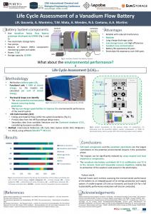
The spring is manufactured by rolling and the washer is manufactured by cutting, and then undergoes a surface treatment by immersion zinc phosphating. The poppet is manufactured by injection moulding, followed by vulcanisation, and the poppet-retainer is made by injection moulding. The component is then obtained by manually assembling these four sub-components. Throughout each sub-component production, there is a loss of raw materials (steel, EPDM and POM). It is assumed that the steel and the POM production wastes are recycled and that the EPDM production waste is incinerated. The four sub-components and their subsequent assembly are performed in Germany. The distances and loads involved during the transportation steps performed by a 28 t truck are indicated in Fig. 1.
Goal and Scope of the Study Goal
The goal of the LCA is to identify options for improving the environmental performance of the car component. The results of this study will be used for product and process development. The component manufacturer wants to be able to analyse the effects of changes in its processes, in terms of technology, inputs and product composition, on the total environmental impact. This information, in turn, can be used to prioritise different measures that can be taken to improve the environmental performance. This LCA does not aim at public comparative assertions, so that an expert review will not be carried out. The study was conducted by INETI, a research institute, within a project coordinated by the com-
Int J LCA 12 (5) 2007
Steel factory (Holand)
Steel factory (Holand)
EPDM factory (Germany)
POM factory (Germany)
Steel 600 km 2.45 km*kg Steel 700 km 9.10 km*kg EPDM 600 km 16.50 km*kg POM 600 km 11.25 km*kg
Spring factory (Germany)
Washer factory (Germany)
Poppet factory (Germany)
Poppet-ret. factory (Germany)
Spring 600 km 2.40 km*kg Washer 700 km 7.28 km*kg Poppet 600 km 6.60 km*kg
Product factory (Germany)
1
Car Components
Poppet-ret 600 km 4.50 km*kg
Fig. 1: The distances and loads involved in the reference scenario
337
Car Components
Automotive Sector
Table 2: Alternative component composition [11]
Sub-components
2.3
Material
Weight (g)
Spring
Wire DIN 2076-D; DIN 17223
3.18
Washer
PA 6.6 + 30% GF
0.939
Poppet
TPV
3.48
PA 6.6 + 30% GF
3.36
Poppet-retainer
Total=10.96
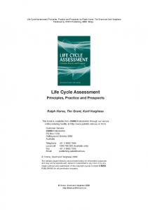
The alternative scenario. The alternative scenario describes the car component after improvements, which focused on the sub-component materials and the production process. In this scenario, the spring is made of steel, the poppet is made of a thermoplastic (TPV) and the other subcomponents are made of PA6.6 with 30% of glass fibre. The new composition is indicated in Table 2. In this particular case, the spring is produced by rolling, while the washer, the poppet and the poppet-retainer are made in the same mould by multi-material injection moulding. After having inserted the spring in the same mould, the final multi-material car component leaves the injection machine already assembled, thus avoiding the manual assembly of the 4 sub-components. As a consequence of this integration, the individual production and assembling steps involving the washer, the poppet and poppet-retainer are eliminated. In addition, throughout the whole production process, there is still a loss of raw materials. It is assumed that all these materials are recycled. Finally, for the purpose of this analysis, all production process steps are considered to be performed in Germany, where the distances and loads used in transportation by a 28 t truck are indicated in Fig. 2. Both the current and the new car components have the same function and are made to have the same lifetime of the car where they are assembled. Moreover, being part of the automotive brake system, both car components must comply with precise technical and assurance standards. Therefore, they are produced in order to fulfil these requirements. At the end of its lifetime, it is assumed that the current and the new car component are shredded and that the metallic sub-components are recycled while plastics are landfilled, as practiced in Europe [12].
Steel 600 km 3.89 km*kg
Spring factory (Germany)
Spring 600 km 3.82 km*kg
PA 6.6 + 30% GF
PA6.6 + 30%GF factory (Germany)
600 km ; 2.82 km*kg
TPV factory (Germany)
600 km ; 10.45 km*kg
PA6.6 + 30%GF factory (Germany)
TPV
Product factory (Germany)
Steel factory (Holand)
PA 6.6 + 30% GF 600 km ; 10.02 km*kg
Fig. 2: The distances and loads involved in the alternative scenario
338
Boundaries
The system boundaries were chosen to include the processes related to the production phase, use phase and final disposal phase. The system boundaries for each scenario are represented in a simplified way in Fig. 3 and 4. Though these figures do not exhibit full details, they contain the main processes studied. The electricity production, the fuel production and the transports are presented in the figures in a general way, considering these processes are associated with a lot of other processes. Regarding each scenario, the following details are considered. The reference scenario. The system boundaries for the reference scenario include the following main sub-systems: – Steel (55Si7) production (including raw materials) – Spring production by rolling (cold transforming steel) – Low carbon steel (St14) production (including raw materials) – Washer production by cutting – Washer surface treatment by immersion zinc phosphating (including raw materials) – EPDM production (including raw materials) – Poppet production by injection moulding – POM production (including raw materials, but excluding transport of the raw materials) – Poppet-retainer production by injection moulding – Component production by manual assembling (consisting just of manual assembling, there is the assumption that this process has no environmental impacts) – Fuel production (including raw materials) – Electricity production (including raw materials) – Raw materials transportation from processing site to the sub-component factories – Sub-components' transportation from their respective production site to the assembling factory – Use phase (car use) – Final disposal phase (steel recycling and landfill of EPDM and POM) The alternative scenario. The system boundaries for the alternative scenario include the following main sub-systems: – Steel (55Si7) production (including raw materials) – Spring production by rolling (cold transforming steel) – TPV production (including raw materials) – PA6.6+30%GF production (including raw materials) – Component production by multi-injection moulding – Fuel production (including raw materials) – Electricity production (including raw materials) – Steel transportation to the spring factory – Spring and the plastic materials (TPV and PA6.6+ 30%GF) transportations to the component assembling site – Use phase (car use) – Final disposal phase (steel recycling and landfill of PA 6.6+30%GF and TPV) In both scenarios, the processes regarding auxiliary materials and packaging are excluded from material processing, sub-components and component manufacturing due to data unavailability. The steps regarding product distribution are also excluded.
Int J LCA 12 (5) 2007
Automotive Sector
Car Components
Iron production
Steel production
Limestone production
Manganese production
Carbon black production
HDPE production
Ammonia production
Ethylene oxide production
Sulfuric acid production
Methanol production
Steel St14 production
Steel 55Si7 production
EPDM production
POM production
Washer production (cutting)
Spring production (rolling)
Poppet production (injection m.)
Poppet-retainer production (injection m.)
Zinc production
Phosphoric acid production
Silicon production
Nitric acid production
Immersion zinc Phosphating
Component manufacturing (manual assembling)
Use
Metals recycling
Transports
Plastics landfill
Electricity production
Fuel production
Fig. 3: System boundaries of the main processes within the reference scenario
2.4
Functional unit
The functional unit considered as the base for assessment and comparative analysis of environmental impacts is a single component over 150,000 km of use. That component is assembled in a passenger petrol car with an average mass of 1,080 kg and for 150,000 km of use [12]. The fuel consumption of the reference vehicle is 5.87 kg/100 km and the emissions are evaluated according to car (petrol) I – Idemat 2001 (SimaPro 6.01) and include combustion and fuel production. The emissions associated just to the fuel combustion are presented in Table 3. The two car components under focus within the reference and alternative scenarios are produced in order to have the same life time as the car where they are assembled. Over that time period, the components do not undergo any maintenance or repair. 2.5
Allocation of the use phase
Considering that the product under analysis is part of a car brake system, it represents a percentage of the total car mass lifetime and, consequently, it is responsible just for a fraction of the environmental impact caused by the whole car during its lifetime.
Int J LCA 12 (5) 2007
Table 3: Air Emissions associated with the fuel combustion, over 100 km, of a passenger petrol car with a petrol consumption of 5.87 kg l/100km [8]
Substance
Quantity (kg)
CO2
20
CO
0.58
SO2
0.0029
NOx
0.13
N2O
0.004
Soot
0.0014
VOC
0.083
Based both on the fact that this LCA study refers to a lightweight design process and that the component mass is less than to 20% of the vehicle weight, from a scientific point of view, the incremental method with its mass orientation is an appropriate method for the allocation of a component's fuel consumption [12]. Then, the fuel consumption of the reference component (Cref.comp.) is: Cref.comp. = Cref.veh. x (Mref.comp. / Mref.veh. ) x c
(1)
339
Car Components
Automotive Sector
Limestone production
Iron production
Manganese production
Steel production
Propylene production
Silicon production
HDPE production
Polypropylene production
Steel 55Si7 production
Nitric acid production
Carbon black production
EPDM production
PA6.6 production
TPV production
Glass fiber production
PA6.6+30%GF production
Spring production (rolling) Component manufacturing (multi-injection m.)
Use
Metals recycling
Plastics landfill
Electricity production
Transports
Fuel production
Fig. 4: System boundaries of the main processes within the alternative scenario
And the fuel consumption of the alternative component (Calt.comp.) is: Calt.comp. = Cref.veh. x (Malt.comp. / Mref.veh. ) x c
(2)
Where Cref.veh.
= fuel consumption of the reference vehicle (5.87 kg/ 100 km) Mref.comp = mass of the reference component (16.45x10⁻³ kg) Mref.veh. = mass of the reference vehicle (1,080 kg) Malt.comp. = mass of the alternative component (10.96x10⁻³ kg) c = fuel consumption reduction value (non-dimensional) According to EUCAR (1998), a value of 0.6 for 'c' is considered the most representative in automotive LCA studies [12]. Using equations (1) and (2), the fuel consumption is obtained over the life of the reference vehicle (0.0804 kg) and the fuel consumption over the life of the alternative component (0.0536 kg).
340
3 3.1
Life Cycle Inventory Analysis Data type/Data sources
The life cycle of the car component involves several important processes and a relevant number of interested parties (i.e. raw materials manufacturers, sub-components manufacturers, component manufacturer, transportation companies, recyclers and incineration plants). The quantity of data is therefore very high. To have access to the necessary data set, information from project partners (the component manufacturer, for instance), literature and specialized databases are used. A description of the data sources used is given below. The reference scenario
• Production phase Spring. The spring material is considered equivalent to the' 55Si7 I' steel, as defined in Idemat 2001 database (SimaPro 6.01). The production process is equivalent to the 'Cold transforming steel' process as described in Data Archive database (SimaPro 6.01) where a 2% production waste is considered based on project partners' information.
Int J LCA 12 (5) 2007
Automotive Sector Washer. The washer material is considered to be equivalent to the 'St14 I' steel as defined in Idemat 2001 database (SimaPro 6.01), while the washer production process is considered to be equivalent to the 'Cutting steel shears' process, as described in the Data Archive database (SimaPro 6.01). However, a 20% production of waste is considered, as based upon project partners' information. Regarding the surface treatment, data is obtained from the 'Phosphating (Zni) I' process included in Idemat 2001 (SimaPro 6.01). Poppet. The poppet material is considered to be equivalent to the 'EPDM rubber ETH U' as defined in the ETH-ESU 1996 database (SimaPro 6.01). The poppet production process is similar to the 'Injection moulding' process, as described in the Data Archive database (SimaPro 6.01). However, according to project data, the quantity of production waste considered was 60%, and the electricity consumption by kg of output was 7.6 MJ, which includes the electricity consumption both for vulcanisation and for injection. Poppet-retainer. The inventory data for the poppet-retainer material (POM) was obtained from Chalmers University of Technology [13]. The poppet-retainer production process is similar to the 'Injection moulding' process, as described in the Data Archive database (SimaPro 6.01) However, the quantity of production waste considered was 60% in order to be closer to project data. The steel waste recycling process is assumed to be equivalent to the 'Recycling ferro metals' defined in the Data Archive database (SimaPro 6.01). Accordingly, an estimated transportation distance of 0.25tkm/kg of waste is used. The POM waste recycling process is similar to the activity of 'Recycling plastics (excl. PVC)', as described in the Data Archive database. In this case, the transportation distance considered is 0.15tkm/kg of waste, where POM is to be avoided in the product. The EPDM waste incineration process is equivalent to the activity of 'Incineration plastics (excl. PVC)', as defined in the Data Archive database (SimaPro 6.01). In this treatment process, all transport distances are considered. Transportation distances of materials and sub-components, as referred to in Figure 1, were obtained from project data. In addition, it is assumed that such transportation is done by a 28 tonne truck, which is represented by the 'Truck 28t B250' as defined in the Buwal 250 database (SimaPro 6.01). • Use phase The car component is considered to be assembled in a car equivalent to a 'Car (petrol) I', as defined in Idemat 2001 (SimaPro 6.01) and portraying the characteristics described in section 2.4. • Final disposal phase The steel recycling process is assumed to be equivalent to the 'Recycling ferro metals', as defined in the Data Archive database (SimaPro 6.01). Accordingly, an estimated transportation distance of 0.25tkm/kg of waste is used. The plastics (POM and EPDM) landfill process is similar to the activity of 'Landfill plastics (excl. PVC)', as described in Data Archive database (SimaPro6.01). Int J LCA 12 (5) 2007
Car Components
The alternative scenario
• Production phase Spring. The spring composition is to considered to be equivalent to the '55Si7 I' steel, which is defined in the Idemat 2001 database (SimaPro 6.01). The spring production process is equivalent to the 'Cold transforming steel' process, as described in the Data Archive database (SimaPro 6.01). In addition, a production waste of 2% is considered according to project data. Washer. The washer composition is considered to be equivalent to the 'PA 66 GF 30 I', which is defined in the Idemat 2001 database (SimaPro 6.01). In this moulding process by multi-material injection, the washer, the poppet and the poppet-retainer are made in the same mould, as the injection of each sub-component material is performed in a sequential manner. As a consequence, for LCA purposes, the multimaterial injection moulding process is modelled as consisting of 3 single injection moulding processes (regarding the production of a washer, a poppet and a poppet-retainer, respectively). As far as the washer is concerned, its production process is considered to be similar to the 'Injection moulding' process as described in the Data Archive database (SimaPro 6.01). In addition, according to project data, the quantity of production waste is assumed to be 60%. Poppet. The TPV composition is assumed to consist of 45% PP and 55% EPDM. It is considered that both PP and EPDM are equivalent to 'PP ETH U' and 'EPDM rubber ETH U', respectively, as defined in the ETH-ESU 1996 database (SimaPro 6.01). The poppet production process is assumed to be equivalent to the 'Injection moulding' process that is described in the Data Archive database (SimaPro 6.01). However, according to project data, the quantity of production waste is assumed to be 60% and the electricity consumption of 2.28 MJ per kg of output. Poppet-retainer. The poppet-retainer composition is assumed to be equivalent to the 'PA 66 GF 30 I', as defined in the Idemat 2001 database (SimaPro 6.01). Its production process is considered to be equivalent to the 'Injection moulding' process that is described in the Data Archive database (SimaPro 6.01), although, according to project characteristics, a production waste of 60% is considered. The steel waste recycling process is assumed to be equivalent to the 'Recycling ferro metals' defined in the Data Archive database (SimaPro 6.01). Accordingly, an estimated transportation distance of 0.25tkm/kg of waste is used. The PA6.6+30%GF waste recycling process is considered to be similar to the 'Recycling plastics (excl. PVC)', as described in the Data Archive database. A transportation distance of 0.15tkm/kg of waste is assumed. The PA6.6+30%GF is considered as the avoided product. Regarding the TPV waste recycling process, a similarity with the 'Recycling plastics (excl. PVC)' is considered and, thus, described in the Data Archive database. Accordingly, the transportation distance of one kilogram of waste is taken as 0.15tkm and, in this case, the TPV is the product avoided. Transportation distances, described in Fig. 2, are based on project data. It is assumed that a 28 tonne truck is used
341
Car Components
Automotive Sector
which is equivalent to the 'Truck 28t B250', as defined in the Buwal 250 database (SimaPro 6.01). • Use phase The car component under focus is considered to be assembled in a car equivalent to 'Car (petrol) I', which is defined in Idemat 2001 (SimaPro 6.01), and having the characteristics as described in Section 2.4. • Final disposal phase The steel recycling process is assumed to be equivalent to the 'Recycling ferro metals', as defined in the Data Archive database (SimaPro 6.01). Accordingly, an estimated transportation distance of 0.25 tkm/kg of waste is used. The plastics (POM and EPDM) landfill process is similar to the activity of 'Landfill plastics (excl. PVC)', as described in the Data Archive database (SimaPro6.01). 3.2
Results
Fig. 6: Life cycle solid wastes generation for reference and alternative scenarios
served through the reference and the alternative scenario lifecycles is 6.1 MJ/component and 4.2 MJ/component, respectively, consisting mostly of non-renewable energy.
The inventory analysis and the subsequent impact assessment have been performed using the LCA software SimaPro 6.01. The energy consumption (MJ/component) throughout the lifecycle in each scenario is shown in Fig. 5. In both scenario conditions, the energy consumption is higher during the use phase. This is due to the fuel (petrol) consumption in this particular phase, which is smaller in the alternative scenario because the alternative component has a lower mass. Regarding the reference scenario, the use phase contributes to 66% of the total energy consumption through the entire lifecycle. Regarding the alternative scenario, the use phase is responsible for 64% of the whole energy consumed. During the production phase, the energy consumption is comparatively higher for the reference scenario. This is due to the higher plastic and steel content, to the higher energy consumption in the production sub-processes, and to the longer distances travelled. Finally, the disposal phase has a negative energy consumption, considering the environmental benefits that result from the steel sub-components recycling. As an overview for both scenarios, the total energy consumption ob-
The cumulative life cycle air emissions of carbon monoxide (CO), nitrogen oxides (NOx), sulphur oxides (SOx), nonmethane volatile organic compounds (NM VOC) and particulate matter with a diameter under 10 µm (PM 10) are presented in Fig. 7. Emissions regarding these parameters
Fig. 5: Life cycle energy consumption for reference and alternative scenarios
Fig. 7: Cumulative life cycle air emissions for reference and alternative scenarios
342
The quantity of solid wastes that are generated throughout the lifecycle of each scenario is shown in Fig. 6. In particular, the solid wastes generated in the use phase are negligible when compared to the production phase. In the production phase, the reference scenario accounts for the majority of solid wastes, mainly due to the POM production. The quantity of solid wastes generated in the final disposal phase is similar in both scenarios, being mainly related to the plastics landfill. In a global perspective, the reference scenario accounts for a solid wastes quantity of 20 g/component and the alternative scenario for 13 g/component.
Int J LCA 12 (5) 2007
Automotive Sector
Car Components phase and is basically related with the HDPE production, diesel production and PP production (in the alternative scenario). The PM 10 emissions are also greater in the production phase for the reference scenario and similar in the production and use phases for the alternative scenario. This pollutant concerns the steel production and the production of fuel consumed in the use phase.
Considering the above inventory results, the alternative scenario seems to be environmentally preferable to the reference scenario. 4
Life Cycle Impact Assessment
eurtrophication
acidification
photochemical oxidation
terrestrial ecotoxicity
The results of the life cycle impact assessment obtained using the problem-oriented approach CML 2000 [8;9] with impact categories defined at a mid-point level are presented
marine aquatic ecotoxicity
human toxicity
ozone layer depletion (ODP)
global warming (GWP100)
abiotic depletion
are higher in the reference scenario when compared to the alternative scenario. The carbon dioxide (CO2) emissions, both in the reference and in the alternative scenarios, are 416 g/component and 274 g/component, respectively. This proportion is in agreement with the proportion obtained for the energy consumption (see Fig. 5) and with the large use of carbon-based fossil fuels (petrol and diesel). It could be verified in this study that the use phase accounts for the majority of the life cycle air emissions of CO, NOx and CO2, since these parameters are mostly related with fuel production and fuel combustion that occurs in this phase. The SOx emissions are greater for the production phase in both scenarios and are mostly related with electricity production, processes occurring in refineries (like the burning of residual oil) and with PA66 production in the alternative scenario. The NM VOC emission is also greater in the production
fresh water aquatic ecotox.
Fig. 8: Cumulative life cycle water emissions for reference and alternative scenarios
The cumulative life cycle of waterborne emissions of undissolved substances, oils, COD and BOD5 are shown in Fig. 8. The undissolved substances include also suspended substances and suspended solids. The undissolved substances and the COD parameters are greater for the alternative scenario. Otherwise, the oils and BOD5 parameters are greater for the reference scenario. This study reveals that the production phase is the dominant source for these pollutants with the exception of BOD5, where the main source is the use phase due to fuel (petrol) production. The undissolved substance emission is basically related to the crude production (for later plastics production), POM production (in the reference scenario) and to PA6.6 production (in the alternative scenario), and to diesel and electricity production. For the oil emission, the crude oil transport and the production of diesel are the largest sources. Concerning the COD, it is emitted essentially during EPDM and electricity production processes (for both scenarios) and during the PA6.6 production processes (for alternative scenario).
Fig. 9: Comparative LCIA results for reference and alternative scenarios using the CML 2 baseline 2000 method/West Europe 1995/Characterization
Int J LCA 12 (5) 2007
343
eurtrophication
acidification
photochemical oxidation
terrestrial ecotoxicity
marine aquatic ecotoxicity
fresh water aquatic ecotox.
human toxicity
ozone layer depletion
global warming
abiotic depletion
eurtrophication
acidification
photochemical oxidation
terrestrial ecotoxicity
marine aquatic ecotoxicity
fresh water aquatic ecotox.
Automotive Sector
human toxicity
ozone layer depletion
global warming
abiotic depletion
Car Components
Fig. 10: LCIA results for reference scenario using the CML 2 baseline 2000 method/West Europe 1995/Characterization
Fig. 11: LCIA results for alternative scenario using the CML 2 baseline 2000 method/West Europe 1995/Characterization
in Fig. 9, 10 and 11. This method led to the conclusion that the alternative scenario is environmentally preferable compared with the reference scenario. The values obtained for all the impact categories are smaller in the case of the alternative scenario.
To evaluate the environmental impacts, a sensitivity analysis was performed using an alternative method, which is according to the ISO 14042 recommendation. Eco-indicator 99 [10], as an endpoint-oriented approach, was used for that purpose. Results obtained converge with the conclusions achieved with the CML method, i.e. the alternative scenario has a lower environmental impact than the reference scenario. The alternative scenario exhibits lower results for all the impact and damage categories considered in this method.
The use phase in the reference scenario is the phase which has the greater contribution for the abiotic depletion and global warming. That is due mainly to fossil fuels extraction (crude, coal and natural gas) for petrol production, and to CO2 and N2O emissions during the car use. The use phase also has a main contribution for photochemical oxidation, acidification and eutrophication, which is justified by the great quantities of CO, SO2 and NOx emitted as a result of petrol production and combustion. For the other impact categories, the production phase is the main contributor. The same conclusions can be drawn for the alternative scenario, which exhibits a similar environmental profile (see Fig. 11). 5
Interpretation
The use phase has a great contribution to the global environmental impact. Therefore, the method used to evaluate the impact of this life cycle phase, and particularly the 'use phase' allocation procedure, is very important. Thus, a sensitivity analysis was conducted using a different fuel consumption reduction value (c), in the incremental method. In this study, a c value of 0.6 is used as proposed by EUCAR 1998 [12]. Considering the existing references to other values, a sensitivity analysis was performed using the fuel consumption reduction value suggested by Keoleian, c=0.438 [2]. In such a case, a fuel consumption over the life cycle is obtained of 0.0587 kg for the reference situation and of 0.0391 kg for the alternative component, which results in a decrease in environmental impact during the use phase for both scenarios. Therefore, the reference scenario still has a greater environmental load when compared to the alternative scenario.
344
The sensitivity of the results with respect to the end of life scenario was also tested, taking into account the ELV Directive [14]. It was considered, for both reference and alternative products, that 80% of the steel components are recycled and 20% are landfilled and 100% of the plastics are landfilled. The impact assessment led to the same conclusion: the results obtained for the alternative scenario are lower than those obtained for the reference scenario for all the impact categories. The differences between this final disposal scenario and the studied final disposal scenario are very small; the highest difference is for fresh water aquatic ecotoxicity impact category and is circa 2% and 2.5% for the alternative and the reference product, respectively. 6
Conclusions
Based on the inventory analysis and the impact assessment results, the following main conclusions can be drawn: – the changes on washer, poppet and poppet-retainer materials and the change of the production process to a more integrated one (which eliminates some production steps) result in a multimaterial car component which is environmentally better than the existing one, mainly due to the reduction in component mass and, consequently, in the reduction in fuel consumption and resources consumption (crude and minerals).
Int J LCA 12 (5) 2007
Automotive Sector – the use phase is the main contributor for the abiotic depletion, global warming, photochemical oxidation, acidification and eutrophication. – the production phase has the major contribution for ozone depletion, human toxicity, fresh water aquatic ecotoxicity, marine aquatic ecotoxicity and terrestrial ecotoxicity. – the sensitivity analysis performed in this study allows one to confirm, as a main conclusion, that the alternative scenario is environmentally preferable when compared to the reference scenario. Acknowledgements. This study has been performed within the scope of the Imatech project – In-Mould Assembling Technology, which was financed by the ADI – Agência de Inovação. The authors would like to thank all the project partners, Iber-Oleff- Componentes Técnicos em Plástico, SA; TRW Lucas Varity GmbH; Departamento de Engenharia de Polímeros da Universidade do Minho; Centimfe – Centro Técnológico da Indústria de Moldes e Ferramentas Especiais e Plástico and ITA –Instituto Tecnologico de Aragon, for their collaboration in providing information and valuable data for inventory purposes.
Car Components [4]
[5]
[6]
[7]
[8] [9]
[10]
[11] [12]
References
[1] [2]
[3]
Curran MA (1996): Environmental Life Cycle Assessment. Mc Graw Hill Keoleian G, Spatari S, Beal RT, Stephans RD, Williams RL (1998): LCA Case Studies, Application of Life Cycle Inventory Analysis to Fuel Tank System Design. Int J LCA 3 (1) 18–28 Keoleian GA, Kar K (2003): Elucidating complex design and management tradeoffs through life cycle design: air intake manifold demonstration project. J Cl Prod (11) 61–77
[13] [14]
International Organization for Standards (ISO) (1997): Environmental management – Life cycle assessment – Principles and framework. ISO 14040, Geneva International Organization for Standards (ISO) (1998): Environmental management – Life cycle assessment – Goal and scope definition and inventory analysis. ISO 14041, Geneva International Organization for Standards (ISO) (2000): Environmental management – Life cycle assessment – Life cycle impact assessment. ISO 14042, Geneva International Organization for Standards (ISO) (2000): Environmental management – Life cycle assessment – Life cycle interpretation. ISO 14043, Geneva SimaPro 6 (2004): Analyst 6.0.1, Pré Consultants CML (2001): An operational guide to the ISO-standards – Part 3: Scientific background (Final report, May 2001). Goedkoop M, Spriensma R (2001): The Eco-Indicator 99-A damage oriented method for Life Cycle Impact – The methodology report, 3rd edition Imatech Project (2004): Interim Report – Task T4.2, Junho 2004 (in Portuguese) EUCAR (1998): EUCAR-Automotive LCA Guidelines-Phase 2. Lynne Ridge, Rover Group Ltd. (Coordinator) CIT Ekologik AB (1998): Chalmers Industriteknik, LCI Data Documentation Report Directiva 2000/53/CE de 18 de Setembro de 2000, Jornal Oficial das Comunidades Europeias
Received: March 29th, 2006 Accepted: December 22nd, 2006 OnlineFirst: December 23rd, 2006
Int J LCA 3 (1) 18–28 (1998)
Application of Life Cycle Inventory Analysis to Fuel Tank System Design Gregory A. Keoleian*, Sabrina Spatari, Robb T. Beal, Robert D. Stephens and Ronald L. Williams * Corresponding author: Gregory A. Keoleian, National Pollution Prevention Center, University of Michigan, Ann Arbor, MI 48109-1115, USA Abstract
Life cycle assessment is becoming an important tool for guiding environmental design improvements in the automotive industry. This paper reports the life cycle inventory profiles for two fuel tank systems based on a collaborative effort between the National Pollution Prevention Center at the University of Michigan, General Motors Research and Development, and the National Risk Management Research Laboratory of the U.S. Environmental Protection Agency. Two 31 gallon functionally equivalent fuel tank systems used on a 1996 light duty vehicle were investigated: a multi-layer HDPE tank with a steel shield and PVC coated steel straps, and a steel tank with a HDPE shield and painted steel straps. Overall, the HDPE fuel tank system is environmentally preferable to the steel tank system based on the set of inventory results presented in this investiga-
Int J LCA 12 (5) 2007
tion. The life cycle inventory analysis indicated lower energy burdens for the HDPE tank system and comparable solid waste burdens for both systems. The total life cycle energy consumption for the steel and HDPE tank systems were 4.9 GJ and 3.6 GJ per tank, respectively. The energy consumption and most of the air pollutants inventoried occurred as a consequence of the use phase. The solid wastes were generated primarily during the material production phase for the steel tank (13 kg) and during the end-of-life management phase for the HDPE tank (14 kg). This study also highlights data analysis and modeling challenges, including manufacturing and use phase allocation methods. Keywords: Automotive industry, fuel tank, LCI; fuel tank sys-
tems, LCI; HDPE, fuel tank, LCI; LCI, automotive industry, fuel tank systems; product system design, automotive industry, LCI
345