Available online at www.sciencedirect.com
ScienceDirect Procedia CIRP 41 (2016) 951 – 956
48th CIRP Conference on MANUFACTURING SYSTEMS - CIRP CMS 2015
Light-responsive RFID tags for precise locating of objects in manual assembly verification workshops Bartlomiej Gladysza,b,*, Cezary Lysiaka a HADATAP Ltd, 7 Mlynarska Str., 01-205 Warsaw, Poland Institute of Organization of Production Systems, Warsaw University of Technology, 85 Narbutta Str., 02-523 Warsaw, Poland
b
* Corresponding author. Tel.: +48-668-618-730; fax: +48-22-397-4384. E-mail address:
[email protected],
[email protected]
Abstract The main idea of Interactive Manual Assembly Operations for the Human-Centered Workplaces of the Future (INTERACT) project is to utilize workers’ knowledge on executing manual assembly tasks and include it in the digital tools used to support manufacturing and continuous improvement of human-centered, flexible assembly workplaces. One of the main assumptions of the project is the most accurate and automated simulation, recording and gathering data about operations performed by employees during manual assembly verification workshops. The problem could be approached by design of shop-floor sensing architecture and application of a set of various sensors, including optical sensors and MEMS. However, some manual assembly operations cannot be accurately described by means of optical sensors and MEMS. Generally, the problem is the accurate identification and location of small objects that are close to each other. One example is mounting a screw in a thread during tail light assembly of a car. This is the case, when threads are in close proximity of each other. Information if a screw was mounted in a proper thread is expected. Therefore, in order to avoid manual supplementation of this kind of data, light-responsive RFID tags are proposed to be applied. Authors described light-responsive RFID idea and the concept of its application in manual assembly verification workshops. First experiments of exemplary application of the concept for screwing operations performed with cordless angle screwdriver are presented. Issues related to the integration of hardware and software components of light-responsive RFID with other hardware and software components are discussed. © 2015 2015 The The Authors. Authors. Published Published by © by Elsevier Elsevier B.V. B.V. This is an open access article under the CC BY-NC-ND license Peer-review under responsibility of the Scientific Committee of 48th CIRP Conference on MANUFACTURING SYSTEMS - CIRP CMS (http://creativecommons.org/licenses/by-nc-nd/4.0/). 2015. Peer-review under responsibility of the scientific committee of 48th CIRP Conference on MANUFACTURING SYSTEMS - CIRP CMS 2015 Keywords: light-responsive RFID; manual assembly; INTERACT
1. Introduction Manual assembly verification workshop is one of industrial pilot use cases defined within INTERACT (Interactive Manual Assembly Operations for the Human-Centered Workplaces of the Future) project [1]. The general concept of the project assumes that workers knowledge on execution of manual assembly tasks could be utilized to support digital tools and help to reduce physical prototypes. Utilization of workers’ knowledge could be based on observations and such observations should allow for automated gathering of data on performed tasks. Such data could serve as input for simulations. Worker’s simulation will be enabled by design of motion synthesis algorithm [2]. The algorithm will be fed with work
tasks descriptions in controlled natural language [3], CAD data and statistical motion database. The database will be formed using motion capture. INTERACT assumption is that data will be gathered with low-cost and non-intrusive means. One of the issues to be addressed is design of a network of sensors, which will allow for data gathering. Most operations could be addressed and recorded with optical sensing [4] and MEMS [5]. Some issues related to motion capture in INTERACT were presented by Manns, Nestor and Arteaga [6]. However, some requirements for manual operations are specific and technologies listed above are not satisfactory.
2212-8271 © 2015 The Authors. Published by Elsevier B.V. This is an open access article under the CC BY-NC-ND license (http://creativecommons.org/licenses/by-nc-nd/4.0/). Peer-review under responsibility of the scientific committee of 48th CIRP Conference on MANUFACTURING SYSTEMS - CIRP CMS 2015 doi:10.1016/j.procir.2015.12.095
952
Bartlomiej Gladysz and Cezary Lysiak / Procedia CIRP 41 (2016) 951 – 956
2. Manual assembly verification workshop Automotive companies need to release customized vehicle to fulfill customer requirements. Functional features are important, but also quality of production process has to be assured to achieve best quality and efficiency of the process. Processes are verified before production run starts. First constructability must be checked. Once it is confirmed, manual assembly verification workshop can start. Currently workshops are executed with physical prototypes by evaluation of the execution of consecutive tasks. If there are process variants tasks are executed as many times as number of variants is. Actually employed geometrical process modeling is labor extensive and exploiting experts. Physical prototypes are leading to significant increase of costs, if considering growing number of car types and variants. Workshops without physical prototypes could effect in decrease of costs and shorten time to market. Pilot cases require, inter alia, high realism, full coverage and an objective interpretation of whether all of worker's activities match a textually described process. It makes even the smallest action of process is important and should be recorded. 3. Sensors’ network 3.1. Requirements and technologies There were listed three types of potentially tracked objects: 1/ human bodies, 2/ tools, 3/ part and generic object. List of directly detectable parameters was prepared including parameters related to all objects (presence/detection, position and orientation in space, dimensions, contact/collision, weight, material), human body (kinematic model of skeleton / posture, attention / cognition, vital data, forces), tools, parts, etc. (forces, acceleration, intrinsic state). Different technologies were analyzed and their abilities to track required parameters were discussed: optical sensing, MEMS (micro electro-mechanical systems) and RFID (radio frequency identification) [7]. Selection of tracking methods should be based on expected precision and resolution. It should minimize amount of data to be processed. Therefore, if only presence/detection is necessary, there is no need to use high resolution optical sensing. Analysis led to the conclusion that optical sensing will form the base of tracking system, as it is the best option for tracking many interrelated points, what is the case of tracking human body (skeleton). Motion capture of worker will be achieved through optical sensing. This base will be enriched with data gathered from MEMS, especially IMUs (inertial measurement units) [8]. However, it is not possible to predict all specific requirements of different manual assembly use cases. It is even not possible to cover all tracking requirements for manual assembly verification workshop pilot case, so tracking system must be flexible, because adding additional sensors may be necessary when considering specific use case. RFID technology will be considered to support some situations, when optical sensors are not feasible to track
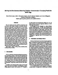
position with required accuracy. Generally, the accuracy of RFID-based real-time locating systems is not sufficient for INTERACT purposes. However, in some cases only identification and/or presence detection of objects in close proximity is required. Both situations could be served with RFID. A case study of a problem faced within automotive pilot case and a concept of light-responsive RFID-based solution is described in paragraph 4. 3.2. Topology One of components of the platform is sensors' network. Its core goal is to serve the most accurate and automated recording and gathering of data about operations performed by employees during manual assembly verification workshops. It is achieved by a set of various sensors, which are managed by three specialized sub-networks: optical (Kinect v2 depth cameras), wireless (foot, grasp and inertial measurement units), and tool (e.g. screwdriver, lightresponsive RFID). To provide full sensors' capabilities, all sub-networks are managed by administrating component of the system – Sensor Management Platform that is also an endpoint to other parts of the platform (see Fig. 1). Network enables monitoring of several parameters in order to provide suitable input data for other INTRACT system components for further analysis. Parameters are related to the human body, objects, parts, assets and tools that are involved in work tasks. 3.3. Light-responsive RFID Due to the fact that low-cost is important quality, passive RFID is the only option to be considered. Traditional RFID system is solely based on radio frequency. All tags that are in range of RFID reader (interrogator) are detected and identified. In some cases this is the shortage, as user needs to identify only specified tag and needs to accurately distinguish between tags that are present and are read. Light-responsive RFID (LR RFID) was examined as possible answer for such issue. The idea is that only one tag from the readable population could be targeted. Solution is based on light beam that is a trigger. If the tag (or group of tags) is illuminated, then it responds to interrogator, else it is not detected. Tags are responding only, if illuminated by proper light beam and they are not working, if only lying in daylight. General idea of the light-responsive RFID is illustrated on Fig. 2. The term “light-responsive” is not the only one that is used. INTERACT Platform Sensor Management Platform
Optical Sensors Network
Tool Sensors Network
Wireless Sensors Network
Fig. 1. Sensor network and management platform.
953
Bartlomiej Gladysz and Cezary Lysiak / Procedia CIRP 41 (2016) 951 – 956
delays in design of a prototype. For two verification workshops defined within pilot cases, for middle console preassembly ca. 10% and for tail light assembly ca. 9% of all work tasks could be classified in a category of “tighten with cordless screwdriver”. The problem can be generalized to recognition of small and close parts assembly. LR RFID readers could solve stated problem. The idea is to:
Fig. 2. (a) Traditional RFID; (b) Light-responsive RFID.
The concept is novel and some researchers and practitioners use terms like “light enabled”, “light activated”, “light selectable”, “light sensitive”, “light controllable”, “visible” to define this specific RFID technology. Sometimes “visible/visual” refers to tags equipped with display (e-paper). Marquardt, Taylor, Villar and Greenberg proposed approach to make RFID tags visible and controllable [9]. However, the goal of their research was to make RFID activity visible (and/or controllable) for user. They achieved visibility of tag’s operations through incorporation of LED light, piezo speaker, and motor for vibro-tactile feedback in tag’s design. They also designed tags with on/off features: on/off switch, on/off button, antenna length switch, touch-, tilt-, light- and pressure-sensitive tags. One proposed design is light-sensitive tag that is responding in normal daylight and not responding in darkness. Gruda, Pinto, Craelius, Davidowitz, Kopacka, Li, et al. [10] proposed and applied light activated microtransponders to tag mice. Same solution could be used for tagging other small animals [11-13], but the critical limitation is the small read range. Many authors [14-16] examined differences between RFID and barcodes (BC). If considering differences between LR RFID and BC, the most important is that LR RFID uses light only to illuminate and activate tag. Therefore, it is much easier to stab tag than with classic BC, the source of light could be minimized and reading distance is more dependent on RFID than on quality of the source of light (camera). Even though line-of-sight is needed for source of light and tag, there is no line-of-sight requirement for RFID reader and tag. LR RFID tags are also more durable and less exposed to conditions of environment, than BC labels. 4. Light-responsive RFID for fastening screws with cordless screwdriver in manual assembly verification workshop The case for which LR RFID will be considered is tail light assembly. According to automotive pilot case, there are tasks in manual assembly process that could not be fully covered by network of optical sensors and MEMS. If considering positioning of the screw threads, there is no sensor that could clearly define, in which thread the screw is mounted. Therefore this information would need to be supplemented manually. There is always a risk of manual data input (forgetting, mistake) that can lead to misunderstandings and
x mark key screw spots with LR RFID tags, x install LR RFID reader to read tags close to screw spots, x install light source on a cordless screwdriver used to screw spots, x gather and combine data from LR RFID and intrinsic data from cordless screwdriver (if and when screw operation was performed), x transfer combined data to sensor network management platform. Reader would identify exact spots where screw is screwed. Classical RFID reader beam is rather wide and the gaps between threads are small, so the solution to be analyzed is usage of LR RFID. Analyzed screwdriver already has built-in led light that highlights screwed spot, so this feature after modifications will be considered to serve as the source of light for LR RFID. During manual assembly an employee has to screw few screws from inside of a vehicle. This operation cannot be seen by any cameras. Only the tool sensor (wireless screwdriver) will provide information if screwing action was performed (via Bluetooth). It lacks any information about position of the tightened screw. LR RFID tags applied closely to thread are illuminated when worker is screwing and LR RFID reader is able to identify proper tag that responds to light. Consecutively the thread where screw was tightened is defined. This information is useful and important, because the sequence of screw assembly impacts ergonomics and quality of assembly. Methodology of conducted research is shown on Fig. 3. There are several cordless screwdrivers with wireless data transfer features. Basic requirements for screwdriver used in a tail light assembly were angle and cordless type, torque range of 5 to15 Nm. Four models of angle and cordless screwdrivers meeting torque range requirement from four market leaders were assessed [17-20]. All models were satisfactory in terms of accessibility of intrinsic data. None of models act as WLAN server itself, but all are accessible via dedicated controllers that are directly connected to computer. Analysis of existing LR RFID solutions
Analysis of existing wireless data transfer features in cordless screwdrivers
Definition of possible applications of existing solutions
Concept of new/improved solution
Fig. 3. Methodology.
954
Bartlomiej Gladysz and Cezary Lysiak / Procedia CIRP 41 (2016) 951 – 956
The model chosen for research was Makita BFL201R that is able to communicate via Bluetooth. The tool is able to communicate, inter alia: x x x x
tool ID, target and final torque value and tolerance, target and final angle value and tolerance, error code (OK/nOK e.g. exceeding torque).
Listed parameters of chosen screwdriver satisfy pilot case requirements. Predominant parameter of chosen tool was its cost, as low-cost characteristic is one of the assumptions for sensors’ network. There were only two LR RFID solutions found on the market, but none was fully satisfactory. Approach used by several authors for animal tagging [10-13] does not meet reading distance requirement. Tags are read typically from less than 7 mm and it is not possible to install reader into screwdriver. The system [21] marketed on logistics market was setup in laboratory and tested. The solution is based on UHF frequency and EPC Cl1 Gen2 / ISO18000-6C standard protocol [22]. Tags could be illuminated with dedicated light source from up to 1 m, what is enough as source of light is planned to be applied directly in screwdriver. Achieved reading distance of RFID reader was up to 5 m, what is also satisfactory, as there is no problem to find place to mount RFID reader for pilot case workshop. Solution is reliable (100% read rate) and reading distance is enough for pilot case. However, solution should be excelled in terms of passive character (it is battery assisted passive) and dimensions of tags. Dimensions are ca. 7.9u3.6u0.9 cm. Big part of a tag is its coin battery (lithium 3V CR2450 [23], 24.5u5.0 mm). Low-cost requirement for tags is met, but the unit cost would even decrease significantly, if a battery was eliminated. The tag is based on commercially available EPC Cl1Gen2 compliant Impinj® Monza® X chip (1.6u1.6u0.35 mm) [25] that is featured with I2C [26] control of RF access. There is a processor connected to I2C protocol and photosensitive element. Processor checks signals from photosensitive element and accesses chip if provided with correct sequence of signals. Then the EPC header [27] is changed, what is a base to distinguish non-illuminated tags from those illuminated with proper source of light. Assessed tags when properly illuminated were read using dedicated RFID reader, as well as non-dedicated typical RFID readers. However, implementation of specific filtering rules was necessary for typical readers, filtering is trivial task. An approach to development of a concept of new/improved solution is three-fold: x incorporation of a light source in a cordless screwdriver, x reduction of dimensions of a tag, x elimination of a battery. Rearrangement of a structure of a tag is expected to reduce dimension to ca. 2.5u4.0u1.2 cm. New housing will be designed and 3D printing will be considered. Illumination of front surface of a tag is necessary to read a tag. This is restricting possible options of a physical application of a tag.
New design of housing will take this issue into account and allow for front and side surface illumination. Further research should also focus on elimination of a battery. First engineering attempts to propose specific design of a purely passive RFID tag were made. Tag board design will be based on commercially available EPC Cl1 Gen2 compliant NXP UCODE G2IL+ chip [28]. One of features of the chip is tag tamper alarm. This feature would be integrated with infrared-working photosensitive element and it will be a base to distinguish illuminated and non-illuminated tags. Expected reading distance is critical requirement for purely passive RFID. It determines the size of an antenna of a tag. This restriction causes limited possibility of reduction of tag’s dimensions. Makita BFL201R is able to deliver the finished screwing process parameters tracked in order to determinate, if there were any discrepancies between planned and actual actions. The data message is send by the tool to inform about its settings and results of finished fastening process. In the context of assembly verification workshop important parameters are tool ID, final torque and angle values, fastening process status and error code when applicable. There is also a need for actions' timestamp information, but tool does not deliver any time related information, therefore it is post operation calculated with Bluetooth delays taken into account. LR RFID system is able to deliver the information that clearly defines detection of specific tag. System provides the list of tags’ detections per unit time. In the context of the considered use case parameters are tag ID and detection timestamp. The data message send by the screwdriver to inform about finished screwing action size is 136 bytes described in Tab. 1. Table 1. Data message of screwdriver. Parameter
Length (bytes)
Parameter
Length (bytes)
Tool ID
1
Reserved
5
Target Torque
3
Total Fastening Count
8
Target Torque Tolerance
5
Optional Function
6
Target Angle
6
Gear Ratio
6
Target Angle Tolerance
4
Rotation #Min
6
Final Torque
10
Rotation #Max
6
Final Angle
10
Rundown Finish
4
Status
4
Rundown Rotation
6
Battery Voltage
5
Reserved
4
Reserved
5
Error Code
4
Reserved
5
ModeID + DataID
4
Reserved
5
Data SUM
4
Reserved
5
Rundown Finish
4
Data collected from screwdriver and LR RFID is merged (see Fig. 4a) in order to define connections between RFID reads and fastening operations and therefore clearly tie fastening action and a specific thread. Fusion mechanism consists of algorithm that compares timestamp of fastening action and LR RFID tags detection history (see Fig. 4b).
Bartlomiej Gladysz and Cezary Lysiak / Procedia CIRP 41 (2016) 951 – 956 a)
Tool
LR RFID
Tool data gathering
RFID data gathering
Fusion
Sensor Management Platform
b) START
Receive of tool and LR RFID data Get specific fastening action Data does not exists
STOP
Data exists Receive of tool and LR RFID data Get 2 sec. before finish of fastening action of LR RFID data Data does not exists Data exists Check history of tags’ detection percentage (for each tag) Get tags with detection rate > 80% 1 tag in detection history >1 tags in detection history Get the one with the highest detection rate
>1 tags in detection history
Assign tag to fastening action
1 tag in detection history
Get default tag
Inform user of default tag selection
Fig. 4. Tool and LR RFID data fusion: a) idea; b) algorithm.
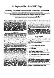
According to the manufacturer’s documentation average Bluetooth communication between the tool and the receiver time is 1105.3 ms. A series of 100 experiments was conducted, to check it. The results are similar to documentation statement (see Fig. 5). Average Bluetooth communication delay is 1182 ms with standard deviation of 304 ms. 5. Conclusion The idea and prototype solution of LR RFID application for detection of small objects and workshop operations hardly detectable by other sensors was outlined.
Fig. 5. a) Communication delay for analyzed screwdriver; b) Deviations for communication delay for analyzed screwdriver.
Preliminary tests led to conclusion that developed approach is still considered the best solution to the set objectives. Further research plan is focused on detailed testing of the solution. Set of tests will be executed: x multiple tags test – longest distance test (ca. 20 cm), x multiple tags test – medium distance test (ca. 10 cm), x multiple tags test – shortest distance test (ca. 5 cm). Experiments will be designed to prove usability of adopted approach to pilot automotive case. Two issues will be tested: achievable distance between a reader and tags, achievable distance between light beam and tags. Reading distances in designed experiments satisfy use case requirements. In order to fulfill high user requirements further hardware development is necessary. LR RFID should be integrated with the tool in a way that does not limit any of the advantages of the tool (ergonomics and simplicity of operation). The integration is essential because the user should be equipped with the tool that is already used. No additional equipment is allowed. For the considered use case, very often threads are in a close proximity to each other. This makes the size of tags crucial for versatility of the solution. Tags should be as small as possible. Theirs size mostly is dictated by the battery so research should focus on developing battery-less tags.
955
956
Bartlomiej Gladysz and Cezary Lysiak / Procedia CIRP 41 (2016) 951 – 956
Battery-less approach is also beneficial from ease of solution maintenance point of view. The main limitation of current research, that needs improvement, is the size of tags, so research plan is focused on this issue. Acknowledgements Research was conducted within INTERACT project. INTERACT has received funding from the European Union Seventh Framework Programme (FP7) under grant agreement n° 611007. Project duration is 2013 Oct 01 – 2016 Sep 30. References [1] INTERACT | Interactive Manual Assembly Operations for the HumanCentered Workplaces of the Future portal [Internet]. Patras, Greece: Laboratory for Manufacturing Systems & Automation, University of Patras; 2013 [cited 2015 Feb 05]. Available from: http://www.interactfp7.eu/ [2] The INTERACT project – YouTube [Internet]. [Place unknown]: interactfp7; 2014 Dec 11 [cited 2015 Feb 08]. Streaming video: 2:08 min. Available from: http://youtu.be/4MZpJXRTsIk [3] Manns M, Wallis R, Deuse J. Automatic proposal of assembly work plans with a controlled natural language. 9th CIRP Conference on Intelligent Computation in Manufacturing and Engineering; 2014 Jul 22-25; Naples, Italy. [4] Yasin M, Harun SW, Arof H, editors. Optical Sensors - New Developments and Practical Applications. InTech, DOI: 10.5772/57077; 2014. [5] Lyshevski SE. MEMS and NEMS: systems, devices, and structures. Boca Ranton (FL), USA: CRC Press; 2013. [6] Manns M, Nestor A, Arteaga M. Improving A* walk trajectories with Bsplines and motion capture for manual assembly verification. 9th CIRP Conference on Intelligent Computation in Manufacturing and Engineering; 2014 Jul 22-25; Naples, Italy. [7] Finkenzeller K. RFID Handbook: Fundamentals and Applications in Contactless Smart Cards, Radio Frequency Identification and Near-Field Communication. Muller D, translator. 3rd ed. Chichester, UK: John Wiley and Sons; 2010. [8] Ruiz ARJ, Granja FS, Prieto Honorato JC, Rosas JIG. Accurate Pedestrian Indoor Navigation by Tightly Coupling Foot-Mounted IMU and RFID Measurements, IEEE Trans Instrum Meas 2012; 61(1):178189. [9] Marquardt N, Taylor AS, Villar N, Greenberg S. Visible and controllable RFID tags. In: Proceedings of the 28th ACM Conference on Human Factors in Computing Systems; 2010 Apr 10-15; Atlanta (GA), USA. p. 3057-62. Available from: http://tinyurl.com/ldc2dyo [cited 2015 Feb 05] [10] Gruda MC, Pinto A, Craelius A, Davidowitz H, Kopacka WM, Li J, et al. A system for implanting laboratory mice with light-activated microtransponders. J Am Assoc Lab Anim Sci 2010;49(6):826-31.
[11] Chen C, Durand E, Wang J, Zon LI, Poss KD. Zebraflash transgenic lines for in vivo bioluminescence imaging of stem cells and regeneration in adult zebrafish. Development 2013;140:4988-97. [12] Robinson EJH, Mandecki W. Distributed decisions: new insights from radio-tagged ants. In: Sun EC, editor. Ant colonies: behavior in insects and computer applications. Hauppauge, NY, USA: Nova Science Publishers, 2011. p. 109-28. [13] Tenczar P, Lutz CC, Rao VD, Goldenfeld N, Robinson GE. Automated monitoring reveals extreme interindividual variation and plasticity in honeybee foraging activity levels. Anim Behav 2014;95:41-8. [14] White G, Gardiner G, Prabhakar GP, Abd Razak A. A comparison of barcoding and RFID technologies in practice. J Inf IT Organ 2007;2:11932. [15] Chan HL, Choi TM, Hui CL. RFID versus bar-coding systems: Transactions errors in health care apparel inventory control, Decis Support Syst 2012;54(1); 803-11. doi:10.1016/j.dss.2012.08.004. [16] Choi Y, Ha H, Park H, Kim H, NamGung K. The RFID Effectiveness Statistical Analysis Tool (RESAT) for Comparing RFID and Barcode in Logistics Operations. In: Lee G, Howard D, Slezak D, Hong YS, editors. Convergence and Hybrid Information Technology. Communications in Computer and Information Science (vol. 310). Berlin Heidelberg: Springer; 2012. p. 611-18. DOI: 10.1007/978-3-642-32692-9_77. [17] Cleco 47BAWSB15AM3DC [Internet]. Westhausen, Germany: Apex Tool Group; 2014 [cited 2015 feb 17]. Available from: http://tinyurl.com/klflafg [18] Makita BFL201R [Internet]. Aichi, Japan: Makita; 2007 [cited 2015 Feb 17]. Available from: http://tinyurl.com/otbhvw6 [19] Bosch BT Angle Exact 17 [Internet]. Stuttgart, Germany: Robert Bosch; 2005 [cited 2015 Feb 17]. Available from: http://tinyurl.com/q5xgs38 [20] AMT HCXBW1025WV38 [Internet]. Aalen, Germany: Alfing Montagtechnik; 2011 [cited 2015 Feb 17]. Available from: http://tinyurl.com/mhrad2r [21] Visible RFID System [Internet]. Suwon, Korea: IDRO [cited 2015 17 Feb]. Available from: http://tinyurl.com/kdwvkyy [22] EPC™ Radio-Frequency Identity Protocols Generation-2 UHF RFID [Internet]. Brussels, Belgium: GS1 Global; 2013 [cited 2015 Feb 17]. Available from: http://tinyurl.com/n5vmaah [23] IEC 60086-SER ed1.0 :2014 Primary batteries [24] ISO/IEC 18000-6:2013 Information technology -- Radio frequency identification for item management -- Part 6: Parameters for air interface communications at 860 MHz to 960 MHz. [25] Impinj® Monza® X-2K Dura Datasheet Rev. 1.51 [Internet]. Seattle, WA, USA: Impinj; 2014 [cited 2015 Feb 18]. Available from: http://tinyurl.com/kwxxb2l [26] I2C-bus specification and user manual Rev. 6 [Internet]. Eindhoven, Netherlands: NXP Semiconductors; 2014 [cited 2015 Feb 18]. Available from: http://tinyurl.com/ybaxnfq [27] EPC Tag Data Standard v. 1.9 [Internet]. Brussels, Belgium: GS1 Global; 2014 [cited 2015 March 26]. Available from: http://tinyurl.com/pk256k8 [28] SL3S1203_1213 UCODE G2iL and G2iL+ Rev 4.4 [Internet]. Eindhoven, Netherlands: NXP Semiconductors; 2014 [cited 2015 Feb 18]. Available from: http://tinyurl.com/kox9rmg