Local Visual Homing by Matched-Filter Descent in Image Distances. Ralf Möller. 1. , Andrew Vardy. 2. 1. Computer Engineering, Faculty of Technology, Bielefeld ...
Biological Cybernetics manuscript No. (will be inserted by the editor)
Local Visual Homing by Matched-Filter Descent in Image Distances Ralf M¨oller1 , Andrew Vardy2 1 2
Computer Engineering, Faculty of Technology, Bielefeld University, 33594 Bielefeld, Germany Computer Science / Engineering & Applied Science, Memorial University of Newfoundland, St. John’s, A1B 3X5, Canada
Received: date / Revised version: date
Abstract In natural images, the distance measure between two images taken at different locations rises smoothly with increasing distance between the locations. This fact can be exploited for local visual homing where the task is to reach a goal location which is characterized by a snapshot image: Descending in the image distance will lead the agent to the goal location. To compute an estimate of the spatial gradient in the distance measure, its value has to be sampled at three non-collinear points. An animal or robot would have to insert exploratory movements into its home trajectory to collect these samples. Here we suggest a method based on the matched-filter concept which allows to estimate the gradient without exploratory movements. Two matched filters — optical flow fields resulting from translatory movements in the horizontal plane — are used to predict two images in perpendicular directions from the current location. We investigate the relation to differential flow methods applied to the local homing problem, and show that the matched filter approach produces reliable homing behavior on image databases. Two alternative methods which only require a single matched filter are suggested. The matchedfilter concept is also applied to derive a home-vector equation for a Fourier-based parameter method.
1 Introduction Local visual homing is the ability of an agent to return to a target location by relating the currently perceived visual information to stored visual information taken at the target location. Visual homing methods received attention both from neuroethology, there as models for the navigation abilities of social insects, and from robotics, where they have been acclaimed as computationally cheap building blocks for topological ap-
proaches to map-building and navigation (Franz et al., 1998a). Since these methods have been extensively reviewed in recent publications (Vardy and M¨oller, 2005; Zeil et al., 2003; Franz and Mallot, 2000), we restrict ourselves to the brief classification shown in figure 1. We leave aside methods based on depth information, since they require multiple cameras, special sensors (St¨urzl and Mallot, 2002), or dedicated movement strategies. Methods where only image intensity is available often derive themselves from the snapshot hypothesis of insect visual homing (Wehner and R¨aber, 1979; Cartwright and Collett, 1983), according to which insects store a relatively unprocessed “snapshot” image of the surroundings of the target location (be it a nest entrance or a food source), and later return to the target location by moving such that the current view gradually becomes more similar to the snapshot. Homing methods based on intensity information can be coarsely classified into correspondence methods and holistic methods. Correspondence methods establish correspondences between local regions in snapshot and current view. Each correspondence is expressed by a shift vector describing the movement of the region from one to the other image. The shift vector can then be transformed into a direction of movement which would reduce the shift. Averaging a number of these movement vectors gives a viable estimate for the home direction. In matching methods, corresponding regions are found by searching for the best-matching region in the neighborhood. The search can be restricted to preselected features (e.g. edges), or each local region can be considered without any preselection. The algorithmic snapshot model suggested by Cartwright and Collett (1983) is the classical representative of a matching method with feature preselection; in this case, the features are dark and bright regions. Matching methods without feature preselection have their roots in methods for the computation of op-
2
Ralf M¨oller, Andrew Vardy local visual homing methods
using depth information
using intensity information
holistic methods
image warping
parameter methods
correspondence methods
DID: descent in image distances
ALV model, contour model, Fourier−ampl. model
differential flow methods first−order, second−order
matching methods
without feature preselection
with feature preselection
block matching, intensity matching, gradient matching
snapshot model
Figure 1 Local visual homing methods. In this paper, we extend parameter methods and the DID method by flow templates and establish a relation with differential flow methods.
tical flow (we refer to these methods as “flow-based matching methods” below). In block matching, the matching is based on the pixel-by-pixel distance between two rectangular regions in the two images, in intensity matching, the block is reduced to a single pixel, and gradient matching searches for the bestmatching gradient (Vardy and M¨oller, 2005). Differential flow methods are derived from Taylor approximations of correspondence equations between intensities (first-order) or between gradients (second-order) under the assumption of small shifts (Barron et al., 1994). Vardy and M¨oller (2005) reported that flowbased matching methods and differential flow methods yield surprisingly robust navigation behavior. This is especially surprising for differential flow methods, since the above-mentioned assumption of small shifts is violated for the long spatial distance between the target and the current location. Also in the matching methods the search was restricted to the vicinity of a region, thus some regions will have moved beyond the search range. Vardy and M¨oller (2005) explain this good performance by the fact that even though the flow fields are of relatively low quality, there is still a sufficiently large number of flow vectors, particularly in the vicinity of the foci of expansion and contraction, which fulfill the assumption of small shifts and therefore produce a concordant vote for the direction of the home vector, whereas the erroneous flow vectors yield uncorrelated movement directions and are therefore overruled. Holistic methods, rather than trying to find correspondences between local regions in the two images, treat the image as a whole. The warping method suggested by Franz et al. (1998b) is essentially a process of “mentally” simulating how different movements would distort (warp) the current image. By searching through
the space of movement parameters for that distorted image which best fits the stored snapshot, the method produces estimates for the home direction, the orientation of the agent, and the distance from home. The search is based on the assumption that all landmarks are found in roughly the same distance from the agent. Due to the large search space, the warping method is only practically feasible if the image is reduced to a horizontal panoramic view of only one pixel height (see also section 5.4). Despite these restrictions, the warping method produces very reliable homing behavior in different environments; it is only outperformed by some flow-based matching methods and differential flow methods which, however, require a compass to align the two images (Vardy and M¨oller, 2005). A sub-class of holistic methods are embraced by the term parameter methods. They are based on the assumption that it is sufficient to only store a condensed description of the snapshot image, a so-called “parameter vector”. Homing is then accomplished by some optimization method, often a simple gradient descent, applied on a distance measure between the parameter vectors obtained from the image at the target location and at the current location. Parameter methods have been suggested as possible explanation for peculiar observations in experiments with desert ants (M¨oller, 2001) and bees (M¨oller, 2000). A special instance of parameter models is the average landmark vector (ALV) model (Lambrinos et al., 2000) where the parameter vector comprises the two components of the average of unit vectors pointing to selected landmark features. While usually in parameter methods the distance measure or “potential” can be computed but the home vector has to be estimated by sampling the potential at multiple locations in space, the ALV method directly provides a home vector (it is equal to
Local Visual Homing by Matched-Filter Descent in Image Distances
3
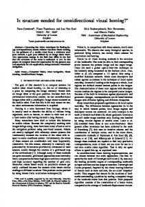
the difference between the two average landmark vectors) whereas the potential can not be computed because it depends on the unknown distances to the landmarks (M¨oller, 2002). While these parameter methods are of mostly theoretical interest, the Fourier-amplitude method suggested by Menegatti et al. (2004) may indeed be suitable for real-world applications. In this method, a panoramic image (with cyclic rows) is characterized by the first few Fourier amplitudes of each row. Since Fourier amplitudes are invariant against shifts, the parameter vector has the desirable property of being invariant against rotations of the agent, and the method can thus be used without a compass. In a recent publication, St¨urzl and Mallot (2006) derived another Fourier-based method from the warping method. Another promising holistic method is the descent in image distances (DID) introduced by Zeil et al. (2003). The method was derived from the observation that, in natural images, the root mean squared error (RMS error) between snapshot and current view smoothly rises with increasing spatial distance between current and target location (see gray tones in figure 2). Thus, similar to parameter models, the target location can be reached by applying a movement strategy derived from some optimization method on the distance measure (here the RMS error). This can be a form of the Gauss-Seidel strategy (move straight while the distance measure decreases, otherwise turn by ±90◦ ) as in the “RunDown” strategy used by Zeil et al. (2003), or the gradient of the distance measure can be estimated repeatedly. For the latter, the agent has to collect at least three samples of the distance measure on noncollinear locations; usually, the three sampling points form a right triangle. The negative gradient estimated from the potential at these three points is the home vector (see vectors in figure 2). In a practical application, however, these movement strategies are not desirable, since they require sharp turns of the robot and increase the overall length of the homeward journey. Especially in applications like cleaning where the robot has to follow a given trajectory, test steps are impractical. Moreover, estimates of the gradient are affected by odometry errors, since the relative position of the sampling points has to be known. In this paper, we suggest a novel method to determine an estimate of the gradient without the necessity of inserting test steps to sample the distance measure. This concept is generally applicable to all homing methods which can be formulated as a gradient descent or ascent in a distance measure. We focus on applying the idea to the DID method since this method is promising for real-world applications and distinguishes itself by its simplicity and low computational complexity. In the discussion we demonstrate the broader applicability by outlining three alternative
Figure 2 DID method applied to an indoor image database (lab environment, see section 4). Gray tones in each square correspond to the RMS error between the image taken at the position in the center of the square and the snapshot image taken in the center of the white square (white: maximal value, black: zero). The home vectors are obtained by estimating the gradient from the RMS values at this and at two neighboring grid positions in perpendicular directions. Left: Home position (5,7). Right: Home position (5,16).
methods derived from the same framework. Being able to save the test steps and instead compute the home vector directly would make a whole class of methods more attractive for applications. The core idea of our approach is to predict how the image would change under two small, mutually perpendicular movements, and to estimate the gradient from the distance measure applied to the current image and the two predicted images. The image prediction is accomplished by projecting the intensity gradient onto two fixed template flow fields or “matched filters” for purely translational movements. These flow fields have a typical form: a focus of expansion in the direction of movement, a focus of contraction in the opposite direction, and regions with approximately horizontal flow between them (see figure 4). The direction of the flow vectors in the two templates does not depend on the distance to the objects in the world, but distance only affects the length of these vectors. Since depth information is not available, we can only assume that all objects are located in approximately the same distance from the current position. The matched-filter method directly delivers the home vector by a pixel-wise summation; both the image prediction and the computation of the distance measure are performed implicitly. Starting from a description which covers both parameter models and the DID method, we derive the matched-filter DID method (MFDID) in section 2. It turns out that MFDID exhibits a structural resemblance
4
Ralf M¨oller, Andrew Vardy
method, a distance measure (potential) p(x) is defined over the plane (coordinate x):
z D . d
p(x) = P {f [C(x)], f [S]}. d γ
y
α
β
x
O
Figure 3 In spherical coordinates, the unit vector d pointing towards a feature of distance D from the origin O is expressed by a horizontal angle β and a vertical angle γ. When the agent moves in direction α in the x-y plane, the feature ˙ shifts in direction d.
to first-order differential flow methods, as tested by Vardy and M¨oller (2005); this relation is analyzed in section 3. The performance of the matched-filter DID method is compared with the original DID method and with a first-order differential flow method by applying it to indoor image databases in section 4. We discuss the experimental results and alternative matched-filter methods in section 5.
2 Derivation of matched-filter DID Notation Let ϕij = (βi , γj )T be a two-dimensional vector of angles in spherical coordinates describing the direction from the vantage point of the camera to the visual feature in the environment which appears at pixel coordinates (i, j)T in the image. The horizontal angle βi varies only with pixel coordinate i, the vertical angle γj only with j (γj = 0 corresponds to the horizon, positive γj are above the horizon). In horizontal direction, the image is closed to a panoramic view. We will omit the pixel index in some steps of the derivation. Figure 3 visualizes the geometrical relations. Also, let x = (x, y)T be the position of the vantage point in the horizontal plane. We assume that the camera coordinate system is aligned with a fixed world coordinate system by using some compass. With C(ϕij , x) we describe a pixel (i, j)T in the image taken at position x. In local visual homing, a snapshot image is captured at the goal location x0 and stored, in the following denoted as S(ϕij ) = C(ϕij , x0 ). If we refer to pixel coordinates, we use the abbreviations Cij (x) = C(ϕij , x) and Sij = S(ϕij ). Entire images are represented by C(x) and S = C(x0 ). All images are assumed to be monochrome. Descent in distance measures In a general formulation covering both parameter methods and the DID
The home vector is the negative spatial gradient of the potential: h(x) = −∇x p(x). The potential is determined by applying a distance measure expressed by P to a feature vector derived from the current view C(x) and a feature vector derived from the snapshot S. The transformation from images to feature vectors is described by the function f . In the ALV model, for example, f would produce the two components of the average landmark vector (Lambrinos et al., 2000); in the contour model, it would amount to a computation of contour length and contour eccentricity (M¨oller, 2001); in the Fourier-amplitude model, f would deliver the first few Fourier amplitudes for each image row (Menegatti et al., 2004). The DID model is a special case where f is the identity mapping: p(x) = P {C(x), S}. More specifically, Zeil et al. (2003) use the RMS error as distance measure s 1 X P {C, S} = RMS{C, S} = [Cij − Sij ]2 N i,j (1) where N is the number of pixels included in the measure. This allows a comparison of image distance values if different parts of the image are excluded from the analysis; Zeil et al. (2003) used this to remove parts of the camera gantry visible in their images. SSE gradient In the matched-filter DID method, we use the sum squared error (SSE) instead of the root mean squared error (RMS, root of SSE normalized to number of pixels) suggested by Zeil et al. (2003). This modification has no effect on the direction of the gradient, but is more amenable to analytical treatment. The SSE between the current image C(ϕij , x) and the snapshot S(ϕij ) is defined as p(x) = SSE(x) =
1X [C(ϕij , x) − S(ϕij )]2 . (2) 2 i,j
The home vector h(x) is the negative gradient of the SSE: (3) h(x) = −∇x SSE(x) X =− ∇x C(ϕij , x) · [C(ϕij , x) − S(ϕij )]. i,j
Local Visual Homing by Matched-Filter Descent in Image Distances
5
Spatial gradient and intensity gradient For small test steps ∆x, the spatial gradient ∇x C(ϕij , x) can be related to the intensity gradient in the following way. A small movement in direction ∆x will cause a small shift of the feature at ϕ in the image by ∆ϕ = ∆ϕ(ϕ, x, ∆x). This shift depends on the movement (∆x) and on the distance to the feature in the environment (and thus on x). By Taylor expansion of C(ϕ + ∆ϕ, x + ∆x) for both arguments at the point (ϕ, x) we obtain C(ϕ + ∆ϕ, x + ∆x) ≈ C(ϕ, x) + ∇Tϕ C(ϕ, x) · ∆ϕ + ∇Tx C(ϕ, x) · ∆x. If we assume that the intensity of the pixel is not changing markedly when the pixel is shifted, i.e. C(ϕ + ∆ϕ, x + ∆x) ≈ C(ϕ, x), we find that −∇Tϕ C(ϕ, x) · ∆ϕ ≈ ∇Tx C(ϕ, x) · ∆x,
(4)
which establishes the relation between the spatial gradient ∇x C(ϕ, x) and ∇ϕ C(ϕ, x), the intensity gradient of the current view. Optical flow For small movements, the shift ∆ϕ can be determined from the flow equation derived by Koenderink and van Doorn (1987): When the coordinate system of the camera moves with speed x˙ and performs a rotation around ω with speed kωk, the flow vector d˙ which describes the visual movement of a feature in direction d (with kdk = 1) and distance D from the vantage point is obtained from x˙ − (x˙ T d)d d˙ = − − ω × d. D
(5)
In our case, the movement is restricted to pure translation, thus ω = 0. For a movement in the x-y plane in direction α and with speed v x˙ = (x, ˙ y, ˙ 0)T = v(cos α, sin α, 0)T , and with d and d˙ expressed in spherical coordinates as ˙ γ) ˙ = (β, ϕ = (β, γ) and ϕ ˙ T , respectively, we obtain µ ¶ µ ¶µ ¶µ ¶ v sec γ 0 sin β − cos β cos α β˙ = 0 sin γ cos β sin β sin α γ˙ D {z }| {z } | Γ B µ ¶ 1 x˙ = ΓB (6) y˙ D where sec γ = (cos γ)−1 . Equation (6) transforms a movement into a flow vector. For a small movement ∆x = (∆x, ∆y)T in the plane, we can approximate ∆ϕ =
1 ΓB∆x. D
(7)
Figure 4 Flow templates for translations in direction e1 (top) and e2 (bottom) obtained from (8). The horizontal axis is β (0 . . . 2π), the vertical axis γ (−1 . . . 1). The lines indicate the horizon (γ = 0) and the maximal / minimal value of γ as well as the range of β. Dots mark the foci of expansion and contraction. The flow vectors are scaled for good visibility.
For movements in the direction of the coordinate axes e1 and e2 with small length η ¿ 1 described by ∆x1 = ηe1 and ∆x2 = ηe2 we see from (7) that ∆ϕ1 =
η ΓBe1 , D
∆ϕ2 =
η ΓBe2 . D
(8)
These equations are describing the two flow templates (matched filters) shown in figure 4. ∆ϕ1 is the flow field experienced under the movement ∆x1 along the x direction, ∆ϕ2 is the flow field for the movement ∆x2 along the y direction. When these flow fields and movements are inserted into (4) we see that each component of the spatial gradient is related to one of the two flow fields. Home vector We are now inserting (7) into (4). For arbitrary ∆x, we obtain the following expression for the spatial gradient: ∇x C(ϕ, x) ≈ −
1 T B Γ∇ϕ C(ϕ, x). D
(9)
Here, D = D(ϕ) is the distance of the feature at angular coordinate ϕ. Since we have no information about object distances, we continue with an equal-distance assumption (see e.g. Franz et al., 1998b): D is assumed to be constant for all directions ϕ. We finally get an equation for the home vector (3) h(x) =
X 1 B(βi )T Γ(γj ) · ∇ϕ C(ϕij , x) · D i,j [C(ϕij , x) − S(ϕij )]. (10)
6
Ralf M¨oller, Andrew Vardy
Image processing For the derivation above, we used angular coordinates ϕij = (βi , γj )T ; if (10) is implemented in an image processing system, however, we have to switch to pixel coordinates (i, j)T to express ∇ϕ C(ϕij , x) by standard filter operations. For simplicity we assume that the image has been preprocessed in such a way that we have an approximately linear relationship between βi and i and between γj and j, like βi = 2π −
2πi , w
γj = γ0 +
C(ϕ + ∆ϕ, x) = S(ϕ).
(γh−1 − γ0 )j h−1
for an image of width w and height h pixels, where i decreases with increasing βi and j decreases with increasing γj . The bottom and top row are corresponding to γh−1 and γ0 , respectively. For equal angle-to-pixel ratios δ in vertical and horizontal direction δ=
2π γ0 − γh−1 = w h−1
By Taylor expansion of the l.h.s for its first argument and approximation to the first order, we get C(ϕ, x) + ∇Tϕ C(ϕ, x)∆ϕ = S(ϕ).
(11)
∇ij Cij (x) can easily be determined from a discrete approximation by applying simple filter kernels like 1 1 T 2 (−1, 0, 1) and 2 (−1, 0, 1) to the pixels of the current image. Since D in (10), δ in (11), and the factor 12 in the kernels are positive constants and just affect the length of the home vector, we can omit these factors from the computation of (10) and determine the home vector from X ˜ h(x) = B(βi )T Γ(γj ) ·∇ij Cij (x)·[Sij −Cij (x)], | {z } i,j Tij
(12) where the matrices Tij can be precomputed. Note that the negative sign in (11) was incorporated into the last factor. The tilde signifies that this home vector is computed from an intensity gradient related to pixel coordinates rather than angular coordinates, and that we omitted the factors as described above; this is the home vector computation used in our implementation.
3 Analysis of matched-filter DID In the following, we investigate the relation between the matched-filter DID method in (10) and the flow vectors computed by a first-order differential method applied to snapshot and current view.
(13)
The solution for this flow equation is not unique due to the aperture problem. Choosing the flow vector ∆ϕ parallel to the intensity gradient, we gain ∆ϕ =
we get βi = 2π − δi and γj = γ0 − δj. We can then express the gradient in pixel coordinates by ! Ã ! Ã ∂β ∂ ∂ ∂i Cij (x) ∂β C(ϕij , x) ∂i ∇ij Cij (x) = ∂ = ∂ ∂γ ∂j Cij (x) ∂γ C(ϕij , x) ∂j = −δ ∇ϕ C(ϕij , x).
Flow-based navigation Vardy and M¨oller (2005) applied first-order differential flow methods to the problem of visual homing. In this application, the flow vector field is determined between the snapshot image S(ϕ) = C(ϕ, x0 ) and the current view C(ϕ, x) with x = x0 + ∆x. First-order methods rest on the assumption that the image intensity is unchanged under a shift ∆ϕ (Barron et al., 1994):
∇ϕ C(ϕ, x) · [S(ϕ) − C(ϕ, x)] k∇ϕ C(ϕ, x)k2
(14)
as one possible solution that fulfills (13) (see e.g. Beauchemin and Barron, 1995). The flow vector ∆ϕ at the pixel in direction ϕ describes the shift of a feature from its position in the snapshot to its position in the current view. By a “vector mapping” method such as the one described by Vardy and M¨oller (2005) or by inverting (7), the flow vector can be transformed into a corresponding direction of movement. Matched-filter DID vs. differential flow The structural resemblance between (14) and the summands in (10) is apparent: The summands are proportional to the flow vector obtained from applying a first-order differential flow method to snapshot and current view. Neglecting the division by the squared length of the intensity gradient, we can therefore interpret the summands of (10) as flow vectors which are transformed into the corresponding direction of movement in the plane; the latter could be called a “local home vector” hij (x) =
1 B(βi )T Γ(γj ) · ∇ϕ C(ϕij , x) · D [C(ϕij , x) − S(ϕij )] (15)
with the overall home vector being determined from summing over i and j. In the following, we establish a relationship between the flow vector obtained from (14), referred to as ∆ϕ∗ij , and the flow vector ∆ϕij corresponding to the local home vector of the matchedfilter DID method in (15). By inserting ∆ϕ∗ij from (14) into (15), we get hij (x) = −
1 B(βi )T Γ(γj )·k∇ϕ C(ϕij , x)k2 ·∆ϕ∗ij . D
Here, D is the average distance to the landmarks which is used in the prediction steps. In contrast to the flow
Local Visual Homing by Matched-Filter Descent in Image Distances
fields obtained from the small test steps in the matchedfilter DID method, the flow vectors relating current view to snapshot are resulting from usually long spatial distances. This violates the assumptions underlying the derivation of (13); nevertheless, differential flow methods seem to produce relatively good homing performance (Vardy and M¨oller, 2005). For our analysis, we assume that the spatial distance between snapshot and current view is small, and can therefore transform hij (x) into the corresponding flow vector as ∆x according to (7): 1 ∆ϕij = Γ(γj )B(βi )hij (x) Dij 1 =− Γ(γj )B(βi )B(βi )T Γ(γj ) · Dij D k∇ϕ C(ϕij , x)k2 · ∆ϕ∗ij . Dij is the true distance to the feature in the world. Since BBT = I, we end with the relation µ 2 ¶ 1 sec γj 0 · ∆ϕij = − 0 sin2 γj Dij D k∇ϕ C(ϕij , x)k2 · ∆ϕ∗ij .
(16)
This is a relation between two flow vectors. On the l.h.s. we find the flow vector ∆ϕij that we would obtain if the agent would move along the local home vector hij (x) produced by the matched-filter DID method. The r.h.s. contains the flow vector ∆ϕ∗ij at the same position in the image which would be produced by a first-order differential flow method when it is applied to snapshot and current view. The negative sign derives from the fact that the local home vector of the matched-filter DID method describes a movement towards the target location whereas the flow vector determined by the differential method describes a movement from the target location to the current location. Furthermore, the relation includes the squared ratio between the length of the gradient and the feature distance which can be explained as a property of the DID method. The DID method establishes a relation between the spatial distance and the image distance. This relation depends on the distance to the feature (the larger the distance of an object, the smaller that object’s impact on the image distance), and on the intensity gradient (the larger the intensity gradient, the larger its influence on the image distance). Finally, the matrix multiplies the horizontal component of ∆ϕ∗ij by sec2 γj and the vertical component with sin2 γj . For the usually small vertical range of the images, the first multiplication should have a negligible effect. The second multiplication reveals that the matched-filter DID method (l.h.s.) seems to underestimate the vertical components of flow vectors close to the horizon (γ = 0) relative to the first-order differential flow method.
7
4 Experiments
4.1 Image Database
The database of images collected by Vardy and M¨oller (2005) is used for all experiments described below. This database is publicly available at www.ti.uni-bielefeld.de/html/ research/avardy. Images from this database were captured by a mobile robot equipped with a panoramic imaging system. This imaging system consists of a camera pointed upwards at a hyperbolic mirror. Images from two different environments are used here. The first environment is a computer lab of dimensions 5.5 × 8.25 m. Within this lab the capture area was 2.7 × 4.8 m with images captured on a grid with 30 cm resolution. The second environment is the main hall of Bielefeld University, a large open space where the distance of viewed objects ranges from several meters to hundreds of meters. The capture grid in the hall had dimensions 4.5 × 10 m at 50 cm resolution1 . All images were captured at approximately the same orientation. If the methods described here were to be used for the online control of a mobile robot, some kind of compass would have to be employed. Since magnetic compasses tend to be problematic in indoor environments, orientation could be derived from visual information; the minimization of image distances over rotation can be used for this purpose as well (Zeil et al., 2003). Raw images from the database were low-pass filtered using a Butterworth filter. The filtered images were then re-projected onto a sphere and unfolded to rectangular images of size 300 × 50. Rows in these images correspond to equal vertical angles above and below the horizon (the center row); columns correspond to equal horizontal angles. The filter parameters were obtained by testing all methods using a variety of parameters and choosing a parameter set that worked well for all methods. The chosen parameters (relative cutoff frequency 0.01, order 3) yield strongly blurred images, an example of which can be seen in figure 5 (bottom). We discuss the impact of low-pass filtering in section 5.1.
1
Images from the ‘lab environment’ come from the original image collection of the database. Images from the ‘hall environment’ come from image collection hall1.
8
Ralf M¨oller, Andrew Vardy
computed from (12), given here again: X ˜ 2 (x) = h B(βi )T Γ(γj ) · i,j
(18)
∇ij Cij (x) · [Sij − Cij (x)].
3. First-order differential flow (FirstOrder): The flow vector computed from the first-order differential flow method (14) is inserted into the inverse of relation (7); if we assume that all visible points are at the same distance D, we can omit D and obtain X ˜ 3 (x) = h B(βi )T Γ(γj )−1 · i,j
∇ij Cij (x) · [Sij − Cij (x)], k∇ij Cij (x)k2
where we applied B −1 = B T . The division by the square of the intensity gradient requires some thresholding scheme to prevent division by nearzero values. We have found that omitting this division leads to an improvement in the algorithm’s performance. Hence, we utilize the following flow expression: X ˜ 4 (x) = h B(βi )T Γ(γj )−1 · (19) i,j
Figure 5 Top: Image (5,7) from the lab. Center: The same image filtered at relative cutoff frequency 0.1 and unfolded. Bottom: Image filtered at cutoff frequency 0.01.
∇ij Cij (x) · [Sij − Cij (x)].
4.3 Assessment 4.2 Methods We compare three different methods (again, the tilde signifies home vectors as they are computed in our implementation, see comment below equation (12)): 1. DID: The original DID method uses a current view and two nearby views in the database to estimate the negative gradient: ˜ 1 (x) = h (17) µ ¶ T T SSE([xm+s , yn ] ) − SSE([xm , yn ] ) − . SSE([xm , yn+s ]T ) − SSE([xm , yn ]T ) Here, m and n relate to the index of the database view on the grid, and s is a step length, also in grid units (if not stated otherwise, we use s = 1, thus views are taken from adjacent grid points). Increasing indices m and n correspond to increasing coordinates on the corresponding axis. When the indices m + s or n + s are lying outside of the grid, [xm−s , yn ]T and [xm , yn−s ]T are taken instead and the sign of the corresponding component is inverted. 2. Matched-filter DID (MFDID): In the matched-filter version of the DID method, the home vector is
Homing performance is assessed by selecting one position in the capture grid as the goal and then applying the homing method to all other positions to obtain a home vector for each. This home vector field is then characterized by two performance metrics, as used before by Vardy and M¨oller (2005). The average angular error (AAE) is the average angular distance between the computed home vecˆ and the true home vector h (the angular distor h tance between these two unit vectors is computed as ˆ T h) ∈ [0, π]). Note that the AAE is a linarccos(h ear statistical measure, not a circular one (Batschelet, 1981). The return ratio (RR) is computed by placing an agent at each non-goal position and allowing it to move according to the home vector for that position. We use steps with a length of 0.5 grid units. If the agent reaches within one grid unit of the goal after a fixed number of steps, the attempt is considered successful (the maximal number of steps is chosen such that the agent could reach the lower right corner of the grid from the upper left corner on an L-shaped course). RR is defined as the ratio of the number of successful attempts to the total number of attempts. As we are interested in robust performance throughout an environment, we test each homing
Local Visual Homing by Matched-Filter Descent in Image Distances
9
method using all capture grid positions in turn as the goal position, and then averaging the results. Henceforth, AAE∗ and RR∗ will refer to the average AAE and RR quantities across all goal positions.
1.8 DID MFDID FirstOrder
1.6
1.4
4.4 Results
AAE*
1.2
1
0.8
Home vectors for all methods for goal positions (5,7) and (5,16) of the lab environment are shown in figure 6. Relatively little difference between the methods is apparent for goal position (5,7), although the performance metrics shown above each vector field indicate that MFDID exhibits the most correct field. The situation for goal position (5,16) is quite different. Here we see excellent performance by FirstOrder, but relatively poor performance by DID and MFDID.
Figure 8 summarizes the results for the hall environment. Here it is MFDID which exhibits both the lowest AAE∗ and the highest RR∗ values. In particular, the RR plots show that this method is the most consistent in this environment. Qualitatively, we find the performance of all methods tested above quite comparable. The method based on first-order differential flow performs better in the lab environment, where both DID and MFDID experience a problem in one small region of the capture grid. In the hall environment, MFDID clearly performs the best of all methods.
5 Discussion 5.1 Analysis of the performance In this section we discuss several issues which are relevant to the performance of the methods studied in this paper. First, we consider the issue of low-pass filtering. As shown in figure 5 (bottom), the filter parameters adopted yield very strong low-pass filtering. To assess the impact on performance we tested all three methods by fixing the order of the Butterworth low-pass filter at 3 and varying the relative cutoff frequency. The results are shown in figure 9. Note that lower cutoff frequencies yield a stronger low-pass filtering effect (i.e. more blurry images). The chosen cutoff frequency of 0.01 appears to be optimal for all methods in the
0.4
0.2 −3 10
−2
−1
10
0
10
10
Cutoff frequency 1 0.9 0.8 0.7 0.6
RR*
Figure 7 presents plots of AAE and RR across all goal positions of the lab environment. For FirstOrder, the performance is generally good throughout. However, for DID and MFDID, the performance is quite poor along the line y = 16.
0.6
0.5 0.4 0.3 0.2 DID MFDID FirstOrder
0.1 0 −3 10
−2
−1
10
10
0
10
Cutoff frequency
Figure 9 Performance of all methods for varying cutoff frequencies (lab environment).
range examined. For smaller cutoff frequencies the performance drops drastically for all methods. For cutoff frequencies higher than 0.01, there is a slight reduction in performance for all methods, except for MFDID as measured by return ratio. Generally, it appears that all methods are relatively insensitive to the filter frequency, as long as it remains higher than 0.01. The performance of both DID and MFDID depends on the spatial structure of the image distance function. For the concept of gradient descent in image distances to be applicable, the two-dimensional image distance function must rise smoothly and monotonically with spatial distance. Figure 2 (left) shows this image distance function for goal position (5,7) in the lab environment. Overlaid on this figure are the home vectors generated by DID. This distance function exhibits the necessary properties: a smooth monotonic rise from the single global maximum. Figure 2 (right) shows the image distance function for goal position (5,16). In this case, the distance function fails to exhibit the desired structure. The absence of a sharply defined attractor point at the goal, as well as the presence of local minima, imply that homing to position (5,16) will not be successful for distant starting positions. In the results
10
Ralf M¨oller, Andrew Vardy DID, AAE: 0.301, RR: 1
MFDID, AAE: 0.178, RR: 1
FirstOrder, AAE: 0.236, RR: 1
16
16
16
14
14
14
12
12
12
10
10
10
8
8
8
6
6
6
4
4
4
2
2
2
0
0
0
0
5
10
0
DID, AAE: 1.14, RR: 0.195
5
10
0
MFDID, AAE: 1.73, RR: 0.231 16
16
14
14
14
12
12
12
10
10
10
8
8
8
6
6
6
4
4
4
2
2
2
0
0
0
5
10
0
5
10
10
FirstOrder, AAE: 0.26, RR: 1
16
0
5
0
5
10
Figure 6 Home vector fields for goal positions (5,7) (top row) and (5,16) (bottom row) in lab environment.
presented above we found poor performance for both DID and MFDID along the line y = 16. The structure of the distance function in this region of the capture grid is likely due to the appearance of the table lying along the top wall of the lab2 . At y = 16, the robot’s camera was practically underneath this table, therefore the top wall was occluded by the darker underside of the table. However, for y < 16 the white wall above the table is more prevalent. Compare the top two images in the left-hand column of figure 10 to the bottom two to see this effect. The impact on the shape of the image distance function is such that DID and MFDID are relatively ineffective for goals in this region. One result which may be surprising is the fact that MFDID consistently outperformed DID. One might suppose that DID would be the better performer given that it actually samples the image distance function, while MFDID only approximates this function. Further, MFDID relies upon an equal-distance assumption which will clearly be unsatisfied in many environments 2 We refer to this as the ‘top wall’ as it corresponds to the top of the plots in figures 6 and 7.
— particularly in the hall environment where MFDID actually performs quite well. We believe that the superior performance of MFDID lies in yet another factor. To estimate the gradient of the image distance function, DID relies on images taken from two adjacent positions in the capture grid. Both of these images are taken from positions 30 cm distant from the current position. MFDID, on the other hand, estimates the gradient using two synthetic images taken from infinitesimally close positions. Thus, the gradient determined by MFDID is more sensitive to the fine local structure of the approximated distance function. To ascertain the impact of this factor we tested DID with increasing step sizes (multiples of 30 cm). The results shown in figure 11 indicate that the optimal step size for DID is less than one. Such a step size is not achievable with this database. It may be the case that for online control of a mobile robot, DID could match the performance of MFDID by decreasing its step size. A possible reason to explain the difference in performance between MFDID and the differential flow method is the underestimation of vertical flow vector components close to the horizon (see section 3). Generally, we found that the differential methods per-
Local Visual Homing by Matched-Filter Descent in Image Distances DID, AAE*: 0.422 (0.2)
11
MFDID, AAE*: 0.298 (0.34)
FirstOrder, AAE*: 0.27 (0.056)
16
16
16
14
14
14
12
12
12
10
10
10
8
8
8
6
6
6
4
4
4
2
2
2
0
0 0
2
4
6
0
8
0
DID, RR*: 0.932 (0.21)
2
4
6
8
0
MFDID, RR*: 0.956 (0.17) 16
16
14
14
14
12
12
12
10
10
10
8
8
8
6
6
6
4
4
4
2
2
2
0 0
2
4
6
4
6
8
FirstOrder, RR*: 0.999 (0.0062)
16
0
2
0
8
0
2
4
6
8
0
2
4
6
8
Figure 7 AAE and RR for all goal positions in lab environment. White represents an AAE value of 0, or an RR value of 1. Black represents an AAE value of 1.8333 (the maximum), or an RR value of 0. The numbers above each plot show the mean and standard deviation (in parentheses).
1
relative to FirstOrder. Images from the lab environment, on the other hand, include a great number of horizontal structures which will tend to exhibit mostly vertical flow vectors.
AAE* RR
*
0.8
0.6
0.4
5.2 Descent methods
0.2 1
2
3 DID step size
4
5
Figure 11 Performance of DID (lab environment) for varying the step size s, see equation (17).
formed well in the lab environment whereas MFDID performed well in the hall environment. Images from the hall environment, as shown in figure 10, are dominated by vertical structures. These vertical structures will tend to exhibit mostly horizontal flow vectors. Thus, in the hall environment, MFDID’s lack of emphasis on vertical flow does not hinder performance
In the following, we discuss the matched-filter DID method and introduce two versions which require only a single flow template rather than two. Homing with two flow templates The matched-filter DID method suggested in this paper derives from a version of the original DID method where the gradient is estimated by sampling the distance measure in two perpendicular directions. We assumed that these test steps originate from the same current location; in a practical application, the robot could sample two points at the beginning and end of a forward movement, and the third point after a ±90◦ turn and a subsequent forward movement, preferably of equal length. The gra-
12
Ralf M¨oller, Andrew Vardy DID, AAE*: 0.606 (0.22)
MFDID, AAE*: 0.339 (0.099)
FirstOrder, AAE*: 0.479 (0.22)
18
18
18
16
16
16
14
14
14
12
12
12
10
10
10
8
8
8
6
6
6
4
4
4
2
2
2
0
0 0
2
4
6
8
0 0
DID, RR*: 0.751 (0.21)
2
4
6
8
0
MFDID, RR*: 0.972 (0.075) 18
18
16
16
16
14
14
14
12
12
12
10
10
10
8
8
8
6
6
6
4
4
4
2
2
2
0 0
2
4
6
8
4
6
8
FirstOrder, RR*: 0.898 (0.18)
18
0
2
0 0
2
4
6
8
0
2
4
6
8
Figure 8 AAE and RR for all goal positions in hall environment. White represents an AAE value of 0, or an RR value of 1. Black represents an AAE value of 1.1343 (the maximum), or an RR value of 0. Notation as for figure 7.
(0,16)
(0,19)
(9,16)
(9,19)
(9,0)
(9,0)
(0,0)
(0,0)
Figure 10 Images from the four corners of the lab environment (left column) and the hall environment (right column). These images were obtained by low-pass filtering (cutoff 0.1, order 3) and unfolding as described in section 4.1.
Local Visual Homing by Matched-Filter Descent in Image Distances
dient would be computed at the second point of this sequence, but applied at the third. Now the core idea of the matched-filter DID is to replace the two test steps with predictions of how the image would change under two small movements. Each prediction is based on a “matched filter” or template flow field for a translation in the corresponding direction. A matched filter is a concept in neuroethology and describes the spatial layout of some population of receptors that is matched to a certain aspect of the task (Wehner, 1987). For example, preferred directions for arrays of elementary motion detectors seem to correspond to flow fields induced by particular movements of flies, e.g. by roll movements (Egelhaaf et al., 2002; Krapp, 2000; Franz and Krapp, 2000; Franz et al., 2004). Our matched filters have the typical structure of flow fields for pure translations in the horizontal plane: a focus of expansion, a focus of contraction, and nearly horizontal flow between them (figure 4). If no depth information is available, though, only the directions of the flow vectors in the two matched filters are known, but not their length. Our prediction therefore rests on an “equal-distance assumption” as the warping method (Franz et al., 1998b). The performance of the matched-filter DID method shows that, as in the warping method, even severe violations of this assumption have only mild effects on the home vector direction. In the matched-filter DID method in equation (12), the intensity gradient of the current image is projected onto the two matched filters (the rows of BT Γ) and multiplied with the difference between the intensity of the pixel in the snapshot and in the current view. This is essentially a comparison between the intensity change in the direction of the flow vector, and the change that would be required to become more similar to the snapshot. If the signs of the two factors coincide, a movement in the direction corresponding to the flow template would make this pixel in the current view more similar to the same pixel in the snapshot. In this case, the local home vector component would be positive (pointing in the template’s corresponding movement direction).
Homing with a single frontal flow template We mentioned above that a matched filter is supposed to correspond to the flow experienced under some typical movement of the animal. In the following we assume that the matched filters are bound to the agent’s coordinate system, with a “frontal” filter where the focus of expansion coincides with the usual movement direction, and a “sideways” filter where the foci of expansion and contraction are at ±90◦ from the movement direction. While the frontal filter will relate to flow ex-
13
perienced under forward translations, the sideways filter is less plausible, at least for walking animals like ants. Moreover, the frontal filter may simultaneously serve some other purpose like path integration; at least for walking insects, it is more difficult to come up with an alternative purpose for the sideways filter. In the following we therefore briefly discuss a version of matched-filter DID where a single matched filter in forward direction is sufficient. We start from the fact that the gradient is the direction with the largest directional derivative, and the assumption that the directional derivative will vary smoothly with varying gaze direction. Probing the directional derivative could be accomplished by small head rotations or small changes in the orientation of the body. For each gaze direction, the directional derivative can be determined by applying just the frontal flow field in the same way as described above for the matched-filter DID method. Turning towards larger values will then gradually align the animal with the home direction. For our case of gradient descent, we can define the directional derivative as µ ¶T cos α H(α, x) = · h(x). (20) sin α Thus, the directional derivative is the projection of the home vector onto a vector pointing in direction α. We now give up the assumption that the agent’s visual coordinate system is aligned with the world coordinates irrespective of its body orientation, but instead assume that the current view is bound to the body of the agent. (For all methods discussed so far, the snapshot would have to be mentally rotated to an orientation matching that of the current view.) Then we can fix the template flow field in the movement direction of the agent’s coordinate system α = 0. We also insert h(x) from (10) and obtain X 1 H(0, x) = eT1 B(βi )T Γ(γj ) · ∇ϕ C(ϕij , x) · D i,j [C(ϕij , x) − S(ϕij )] By comparing this equation to the home vector (10), we see that H(0, x) is just a projection onto the frontal flow filter (focus of expansion in the direction of movement): The intensity gradient is projected onto the first row of BT Γ. By looking into different directions, e.g. just by moving the head slightly from side to side, and predicting the image change through the frontal flow filter, the agent can detect a turn direction in which the directional derivative increases. Figure 12 (center) shows the length of the directional derivative computed in this way for three current locations in different directions. Of course, a similar strategy could also be applied without prediction by actually measuring the change
14
Ralf M¨oller, Andrew Vardy
Figure 12 Matched-filter DID method applied to the lab database. Left: Home vector field for the goal location in the center of the black square, obtained by applying two flow templates. Center: Directional derivative for different gaze directions computed at three different locations, determined from a single frontal flow template. The directional derivative is represented by the length of the gray vectors pointing in the gaze direction. The black vector is the home vector. Right: Trajectories produced by determining the turn direction from a single sideways flow template. From each of the three starting points (black dots), the simulated agent starts with two different initial orientations (looking to the left side of the grid or to the right). The closest view in the database grid to the agent’s position is used for the computation. The agent moves in steps of 0.3 grid units.
of the SSE under small translations. Rather than sampling the SSE at three points in a right triangle, the agent would move one a slightly winding trajectory. After having executed a small translatory movement, the agent determines an approximation of the directional derivative from SSE values sampled at the beginning and the end of this step, changes the heading angle by a small amount, executes another translatory movement, again approximates the directional derivative from two SSE values, and then decides in which direction to turn such that the directional derivative will decrease. This method may be problematic, though, since the two translatory steps do not originate from the same point. Homing with a single sideways flow template In the method described in the previous paragraph, the agent will turn towards an increasing directional derivative. This opens an alternative approach to matched-filter DID which has the advantage of not requiring any sampling movements (not even changes in gaze direction), but which is less plausible with respect to the matchedfilter concept since at least walking animals will rarely experience this flow field. In this approach the agent will not determine a home vector directly, but will determine an amount by which to turn at each step. The
agent can turn according to the derivative of the directional derivative H(α, x) dα ∂H(α, x) =ε , dt ∂α where the term on the r.h.s. can simply be determined from (20): µ ¶T ∂H(α, x) − sin α = · h(x). cos α ∂α Again, we change from fixed coordinates to agentbound coordinates (α = 0) and insert the home vector from (10), which yields ∂H(0, x) X 1 T = e2 B(βi )T Γ(γj ) · ∇ϕ C(ϕij , x) · ∂α D i,j [C(ϕij , x) − S(ϕij )]. A comparison with the home vector in (10) reveals that this equation projects the intensity gradient onto the sideways flow filter (second row of BT Γ). In this filter, the foci of expansion and contraction lie at ±90◦ from the forward direction. The behavior of this method is shown in figure 12 (right): Starting from three different points in two different orientations, the agent is turning towards the snapshot location and approaches this location while moving with constant speed. For the sake
Local Visual Homing by Matched-Filter Descent in Image Distances
of demonstration, we chose a small value for ε; this leads to slow turning and exaggerates the differences between the two trajectories originating at the same point. Since it requires only a single matched filter and has no motor components (no head movements, no translational test steps), this method is clearly attractive for applications where the robot’s task is to approach a target location. The method has its limitations when the local homing method is integrated into topological navigation in a view graph (Franz et al., 1998a) since it does not provide a home vector. For some purposes, for example to select a new direction of exploration at a graph node, it is more efficient if the home vector towards neighboring graph nodes can directly be determined. The method with the single sideways filter would have to physically rotate the robot (or the flow template) into the home direction. Here the matchedfilter DID method using two matched filters is more efficient.
5.3 Other matched-filter methods In the main part of this paper we derived and tested the MFDID method where the matched-filter concept is applied to simplify the descent in image distances (DID) suggested by Zeil et al. (2003). We focused on the DID method because of its simplicity and low computational complexity. However, the matched-filter approach is a more general concept and can be applied to derive closed-form solutions for all methods which are formulated as a gradient descent in a distance measure. With the three methods presented in the following we intend to illustrate the broader applicability of the matched-filter concept. The first two methods adhere to the concept of descent in image distances but use a different distance measure and a different template flow field, respectively, whereas in the third example we derive the matched-filter solution for the Fourieramplitude method (Menegatti et al., 2004). MFDID with different distance measure The DID method is based on the RMS error (1) or the SSE (2) between images, but a number of alternative distance measures could be used as well; Giachetti (2000) gives an overview in the context of block matching. One might conjecture, for example, that the covariance measure p(x) = COV(x) 1 X = [C(ϕij , x) − C(x)] · [S(ϕij ) − S] N i,j (where N is the total number of pixels and the overlined quantities are average image intensities) is more
15
robust against global variations of brightness than RMS and SSE. It is straightforward to derive the home vector for this method by approximating the spatial gradient with the intensity gradient according to (9): h(x) = −
1 X 1 B(βi )T Γ(γj ) · (21) N i,j D ∇ϕ C(ϕij , x) · [S(ϕij ) − S].
(Note that in this case the home vector is obtained from a gradient ascent in the potential.) While MFDID with the SSE as distance measure produces a home vector that may appear to be just a version of the first-order method with a different weighting of the flow vectors (compare (18) with (19)), other distance measures result in solutions such as (21) which are more remotely related to the first-order flow method. MFDID with rotational flow template Both the original MFDID method (10) and the method derived from the covariance measure (21) are using two purely translational flow templates to approximate the gradient. These methods are based on the observation by Zeil et al. (2003) that the image distance is varying smoothly over the spatial distance to the goal. The same authors report that the image distance also changes smoothly when images from two nearby locations are rotated against each other. The distance measure exhibits a pronounced minimum at the angle where the two images are approximately aligned as if they had been captured in the same camera orientation. The rotation angle can either be found by rotating the images through all angles and searching for the minimal SSE, or by a gradient descent in the rotation angle α with respect to the SSE. We can apply the matchedfilter approach to the gradient descent by formulating the distance 1X p(α) = SSE(α) = [C(ϕij , α) − S(ϕij )]2 . 2 i,j Here we omitted the position x of the current view and introduced the rotation angle α as parameter. In this case, our template flow field corresponds to a pure rotation around the vertical axis, i.e. we insert x˙ = 0 and ω = ω(0, 0, 1)T into the flow equation (5). After some manipulations, we obtain the descent equation over the rotation angle α: α˙ = −
X dC(ϕij , α) i,j
dβi
· [C(ϕij , α) − S(ϕij )].
If the agent rotates according to α, ˙ the image distance between the current view and the snapshot is reduced. Note that the test steps for rotation are practically coming for free (the image can be rotated without movements), so this method does not share the advantage of
16
Ralf M¨oller, Andrew Vardy
saving test steps as MFDID; we are mainly presenting this for the sake of demonstrating the general applicability of the matched-filter method. Fourier-amplitude method In the Fourier-amplitude method introduced by Menegatti et al. (2004), each image is characterized by the first K amplitudes of the Fourier spectra of each row of the panoramic image. Since Fourier amplitudes are invariant against shifts, this method does not require a compass to align the two images before computing the distance. We denote the discrete Fourier transform as ¶ µ n−1 1 X 2π Fk (I) = √ Ii exp −ıki n n i=0 where n is the number of pixels per image row, Ii is pixel i of the image row I, and ı is the imaginary unit (see e.g. J¨ahne, 2002). As the distance measure we use the SSE applied to the Fourier amplitudes of corresponding rows j in the two images, a simple formulation would be p(x) =
K 1X X 2 (|Fk (Cj (x))| − |Fk (Sj )|) . 2 j k=−K
Here, Cj (x) and Sj denote row j of the panoramic images. We introduce the two components of the spatial gradient which is approximated by the intensity gradient according to (9), µ ¶ δ Φij (x) = B(βi )T Γ(γj )∇ij Cij (x), Ψij (x) D with δ from (11). The home vector equation is derived in the usual way. We use the abbreviations