Mark Terwilliger, Ph.D. Western Michigan University, 2006. With the proliferation of wireless sensor networks, providing location-aware technology and services ...
LOCALIZATION IN WIRELESS SENSOR NETWORKS
Mark Terwilliger, Ph.D. Western Michigan University, 2006
With the proliferation of wireless sensor networks, providing location-aware technology and services to new applications have become important for developers. Localization is the problem of determining the positions of nodes in an ad hoc network. With the constrained resources of network sensors, providing robust localization services remains a fundamental research challenge facing the entire sensor network development community. The initial localization problem that we addressed was to design and develop a working system that could locate equipment, such as a laptop or video projector. Ferret, the localization system developed, uses two different ranging techniques to help locate an object to within one meter. Our next goal was to identify the locations of all nodes in a sensor network given the locations of a small subset of nodes. The system we developed, LESS or Localization using Evolution Strategies in Sensornets, provides substantial energy savings over existing techniques while providing comparable accuracy. We then introduce an efficient location discovery algorithm that bounds the localization error. Our algorithm, based on finding the smallest circle enclosing the intersection of n disks, runs in O(n2) time. We extend our work to the problem of finding
the smallest disk that includes the set of points common to n disks and excluded from the interiors of m other disks. Many localization techniques say that a node can either be localized or it cannot. We present a location discovery algorithm that provides, for every node in the network, a position estimate, as well as an associated error bound and confidence level. We provide a versatile framework that allows users to perform localization queries based on the required accuracy and certainty. Ensuring coverage of a wireless sensor network is critical in many applications. Most schemes that analyze and implement coverage assume that sensor locations are known. For large sensor networks, errors occur when estimating node positions. Based on the errors that arise from the localization process, we present coverage algorithms that associate a confidence level with the coverage. We introduce a system that handles user coverage queries based on the coverage and certainty a situation requires.
LOCALIZATION IN WIRELESS SENSOR NETWORKS
by Mark Terwilliger
A Dissertation Submitted to the Faculty of The Graduate College in partial fulfillment of the requirements for the Degree of Doctor of Philosophy Department of Computer Science
Western Michigan University Kalamazoo, Michigan April 2006
Copyright by Mark Terwilliger 2006
ACKNOWLEDGMENTS
This dissertation is dedicated to my parents Norman and Moreen Terwilliger, two outstanding educators, as well as great inspirations to me. I would also like to thank my wife Kelly and boys Adam and Luke for their support and patience as I have pursued this degree. This work would not have been possible without the encouragement and mentoring from my advisor Ajay Gupta. You have helped me accomplish far more than I ever could have envisioned. This will always be appreciated and remembered. I would also like to thank Collette Coullard for collaborating with me. It has been a pleasure working with you. Finally, I would like to thank my committee members Mohsen Guizani, James Yang, and Song Ci. Your feedback and support has been greatly appreciated.
Mark Terwilliger
ii
TABLE OF CONTENTS
ACKNOWLEDGMENTS ......................................................................................
ii
LIST OF TABLES..................................................................................................
vi
LIST OF FIGURES ................................................................................................
vii
CHAPTER I.
II.
III.
INTRODUCTION ......................................................................................
1
WSN Challenges................................................................................
3
Localization Problems .......................................................................
5
Our Results ........................................................................................
6
BACKGROUND AND RELATED WORK ..............................................
9
Ranging Phase....................................................................................
10
Localization Phase .............................................................................
11
Existing Localization Systems...........................................................
15
Localization Systems Using Wireless Networked Sensors ...............
18
Locating All Nodes ............................................................................
21
LOCATING A SINGLE OBJECT .............................................................
23
Introduction........................................................................................
23
The Potentiometer Technique............................................................
26
The RSSI Technique..........................................................................
27
Ferret Software ..................................................................................
29
Performance Results ..........................................................................
31
iii
Table of Contents—Continued
CHAPTER
IV.
V.
VI.
Conclusions and Future Work ...........................................................
34
LOCALIZATION OF AN ENTIRE NETWORK......................................
36
Introduction........................................................................................
36
The LESS System ..............................................................................
38
Performance Results ..........................................................................
42
Conclusions and Future Work ...........................................................
47
BOUNDING THE LOCALIZATION ERROR .........................................
50
Introduction........................................................................................
50
Definitions and Problem Formulation ...............................................
53
The Disk Problem ..............................................................................
54
The Washer Problem .........................................................................
68
Performance Results ..........................................................................
71
Conclusions and Future Work ...........................................................
78
LOCALIZATION WITH CONFIDENCE .................................................
81
Introduction........................................................................................
81
Locating an Object with Confidence .................................................
83
Localization Queries ..........................................................................
86
Localizing an Entire Network with Confidence ................................
88
Performance Results ..........................................................................
93
iv
Table of Contents--Continued
CHAPTER
VII.
VIII.
Conclusions and Future Work ...........................................................
102
COVERAGE WITH CONFIDENCE .........................................................
104
Introduction........................................................................................
104
Coverage Queries...............................................................................
108
Related Work and Background..........................................................
110
Coverage With Confidence................................................................
113
Performance Results ..........................................................................
121
Conclusions and Future Work ...........................................................
128
CONCLUSIONS AND FUTURE WORK .................................................
130
Summary............................................................................................
130
Extensions and Future Research ........................................................
132
REFERENCES ...........................................................................................
138
APPENDIX – Ferret Location System Software........................................
143
v
LIST OF TABLES
1.
Localization Systems ..................................................................................
18
2.
Power Versus Distance Relationship..........................................................
25
3.
Localization Systems Using Wireless Networked Sensors ........................
34
4.
Confidence Properties of Three Disks ........................................................
85
5.
Example Localization Queries and Their Results.......................................
93
6.
The neighbor_count Vector for One Point .................................................
118
vi
LIST OF FIGURES
1.
Trilateration ................................................................................................
11
2.
Localization with Maximum Bounds .........................................................
12
3.
Triangulation...............................................................................................
13
4.
Localization with Maximum Likelihood ....................................................
14
5.
The Mica Mote............................................................................................
23
6.
The Ferret Interface ....................................................................................
24
7.
The Calibration Tool Algorithm .................................................................
25
8.
Output from the Ferret System ...................................................................
27
9.
Experimental Results Plotting Distance Versus RSSI................................
28
10.
Accuracy of Potentiometer Technique .......................................................
32
11.
Accuracy of RSSI Technique .....................................................................
32
12.
Variability of the Two Techniques .............................................................
33
13.
Time to Locate for the Two Techniques.....................................................
34
14.
How Mutation Affects Localization Error..................................................
41
15.
Screen Shot of the LESS System ................................................................
43
16.
Position Error Comparison .........................................................................
45
17.
Effect of Anchor Node Density with LESS................................................
46
18.
Power Consumption Comparison ...............................................................
48
19.
A Disk .........................................................................................................
50
20.
A Washer ....................................................................................................
51
vii
List of Figures—Continued
21.
The Smallest Circle Enclosing the Intersection of Three Inclusion Disks .
52
22.
Boundary of Circle Segment.......................................................................
57
23.
Circle Intersecting Segments ......................................................................
57
24.
Segment of a Circle Intersecting Two Disks ..............................................
58
25.
Intersection Points of a Circle With Two Disks .........................................
58
26.
Intersection Points of a Circle With Two Disks .........................................
59
27.
Three Configurations of Two Disks ...........................................................
60
28.
Antipodal Points .........................................................................................
61
29.
Final Plus/Minus Pair is Found for a Circle ...............................................
63
30.
The Processing of the Plus/Minus Pairs .....................................................
64
31.
If Antipodal Point Lies in Intersection, Then Solution is Smallest Disk....
65
32.
The Intersection of Solution Segments with a Disk ...................................
67
33.
The Washer Problem ..................................................................................
69
34.
The Intersected Region is Broken into Multiple Pieces .............................
70
35.
Screen Shot of Network Localization System ............................................
71
36.
Comparison of Disk and Washer Methods .................................................
73
37.
Effect of Anchor Density on Localization Error ........................................
75
38.
Varying the Maximum Ranging Error........................................................
76
39.
Comparing Different Anchor Configurations.............................................
78
40.
Location Estimate from a Single Point .......................................................
83
viii
List of Figures--Continued
41.
The Intersection of Three Disks..................................................................
84
42.
The Localization with Confidence System .................................................
87
43.
Localizing a Node Using Multi-hop Paths .................................................
89
44.
A Sensor Network with Location Estimates...............................................
91
45.
Examining Percentage of Nodes within the Error Bound with Varying Confidence Level and Sigma ......................................................................
95
46.
Effect of Ranging Accuracy on Localization Error ....................................
97
47.
Examining Percentage of Nodes within the Error Bound with Varying Anchor Node Density .................................................................................
99
48.
Effect of Anchor Node Density on Localization Error...............................
100
49.
Effect of Using Shortest Path Routing in a Dense Network.......................
101
50.
A Region Covered by Seven Sensors. ........................................................
105
51.
A Coverage Disk.........................................................................................
106
52.
Coverage Query Classes .............................................................................
108
53.
Covering a Single Point ..............................................................................
114
54.
Finding the 2-Covering of a Point ..............................................................
115
55.
The Coverage with Confidence System......................................................
122
56.
Comparing System Claim Versus Actual Coverage...................................
123
57.
The Effect of Sensing Range on Estimated K-Coverage............................
125
58.
The Effect of Ranging Accuracy on Estimated K-Coverage......................
126
59.
The Effect of Anchor Density on Estimated K-Coverage. .........................
127
ix
List of Figures--Continued
60.
The Effect of Confidence on Estimated K-Coverage .................................
128
61.
A Boundary Map ........................................................................................
135
x
Chapter I INTRODUCTION Advancements in low-power electronic devices integrated with wireless communication capabilities and sensors have opened up an exciting new field in computer science. Wireless sensor networks (WSN) can be developed at a relatively low-cost and can be deployed in a variety of different settings. A WSN is typically formed by deploying many sensor nodes in an ad hoc manner. These nodes sense physical characteristics of the world. The sensors could be measuring a variety of properties, including temperature, acoustics, light, and pollution. Base stations are responsible for sending queries to and collecting data from the sensor nodes. Some of the main characteristics of a networked sensor include: (1) small physical size, (2) low power consumption, (3) limited processing power, (4) short-range communications, and (5) a small amount of storage. The typical size of today's networked sensor is a couple square inches, but the ultimate goal of the SmartDust project is to incorporate sensing, communication, processing, and power source all into the space of a few cubic millimeters [Ka99]. Individually, these resource-constrained devices appear to be of little value. Deploying these sensors in large scale across an area of interest, however, is when they can be most effective. Placing sensors in hostile or inaccessible regions may allow for data collection which was previously impossible. Spatial and temporal processing as well as dense monitoring is now feasible. The sensors must be able to form an ad hoc network and use collaborative techniques to monitor an environment and respond to users when
1
appropriate. Wireless sensor networks provide the means to link the physical world to the digital world. The mass production of integrated, low-cost sensor nodes will allow the technology to cross over into a myriad of domains. In the future, applications of wireless sensor networks will appear in areas we never dreamed. Listed below are just a few places where sensor networks can and will be deployed. • • • • • • •
Earthquake monitoring Environmental monitoring Factory automation Home and office controls Inventory monitoring Medicine Security
Although still in its infancy, wireless sensor network applications are beginning to emerge. A recent study on Great Duck Island in Maine used sensor networks to perform monitoring tasks without the intrusive presence of humans [Ma02]. When monitoring plants and animals in the field, researchers have become more concerned about the effects of human presence. In the Smart Kindergarten project [Sr01], using pre-school and kindergarten classrooms as the setting, the plan is to embed networked sensor devices unobtrusively into familiar physical objects, such as toys. The environment will be able to monitor the interactions of children and teachers in order to promote the development of skills. Researchers at Wayne State University believe implanted biomedical devices called smart sensors have the potential to revolutionize medicine. Proposed applications include an artificial retina, glucose level monitors, organ monitors, cancer detectors, and general health monitors [Sc01]. Realization of sensor networks needs to satisfy the constraints introduced by
2
factors such as fault tolerance, scalability, cost, hardware, topology change, environment, and power consumption. Because these constraints are highly stringent and specific for sensor networks, new wireless ad hoc networking techniques are required [Ak02].
WSN Challenges Although some applications have shown promise, the field of wireless sensor networks still provides many challenges to researchers: Data storage – Sensors are sampling the environment continuously. With the limited storage capacity of the networked sensors, volumes of data cannot be stored permanently. Data has to be compressed and filtered, aggregated with data from other nodes, and stale data must be purged. Should the data be stored in the network or should it be routed offline to a central server? Energy efficiency – Some form of battery typically powers networked sensors. When large networks of sensors are deployed, they are expected to run unattended for long periods of time. Writing energy-efficient algorithms that conserve the battery could extend the lifetime of an application by months. Energy conservation techniques are to be designed at all of the networking layers, from the physical layer to the application layer, and for various applications. Fault tolerance – In early generations of networked sensors, there are high malfunction and failure rates. In most sensor applications, it is not feasible for a human to physically traverse a region to repair and replace nodes. A significant percentage of sensor nodes may fail when deployed in hostile environments. Therefore, techniques must be provided by the system so that the application continues running without
3
interruption when nodes become faulty or die. Localization – Using wireless sensor networks to locate or track things is an application that is attracting much attention lately. There are many sensor network protocols and applications that assume every node knows its location. How is this possible? If every node were equipped with a GPS component, both the financial and energy cost of a large sensor network would become exorbitant. If a small fraction of the nodes are aware of their location, is it possible for the remaining nodes to discover their location? Scalability – The applications that are envisioned for sensor networks in the near future will use thousands of sensors. How do you get thousands of nodes to self-organize and work together? Centralized algorithms must sometimes give way to distributed algorithms when applications are being considered for networks of this scale. The deployment and management of thousands of tiny devices are issues that must be addressed. Security – Any network application that uses a wireless medium inherently assumes a security risk. Eavesdropping to obtain information and jamming to deny service [Wo02] are a couple of ways that a sensor network system may be attacked. The SPINS protocol [Pe01] proposed basic building blocks for authenticated and private communication in sensor networks, but the traditional encryption techniques are not always plausible for the resource-constrained devices. What can be done to make sure a wireless sensor network provides important features such as availability, reliability, freshness, and privacy?
4
Localization Problems This dissertation addresses the challenge of localization in wireless sensor networks. There are a couple of localization problems that are of importance to ad hoc and wireless sensor networks. The first one is trying to locate a person or locate an object, such as a remote control, a set of keys, or even an enemy vehicle. There are many systems that address this problem, some of which are discussed in Chapter II. Another localization problem is trying to find the positions of every node in an ad hoc or wireless sensor network. This standard problem can be defined as the following: "Reconstruct the positions of all the nodes in a sensor network given the relative pairwise distances among all the nodes that are within some radius r of each other." While we are given 1-dimensional measures of the relative distances, we are required to compute the positions either in a 2-dimensional or a 3-dimensional space, which makes the problem interesting and challenging. Throughout this chapter, without loss in generality, we target our algorithms for the resource constrained and energy-critical WSNs, however, our solutions are applicable to more general wireless ad-hoc networks. The localization problem is even more important in wireless sensor networks for the following reasons: 1.
Many WSN protocols and applications simply assume that all
nodes in the system are location-aware. 2.
If a sensor is reporting a critical event or data, we must know the
location of that sensor. 3.
If a WSN is using a geographical routing technique, all of the
nodes must be aware of their location.
5
Given known exact distances between neighbors, the localization problem has been shown to be NP-hard [As04]. An added challenge is the fact that in practice, the exact distances between pairs of sensor nodes are not known. Instead, estimates are used to approximate the distances.
Our Results In our research, the initial localization problem that we set out to solve was one in an office environment. Given a building with many offices, hallways, closets, etc., the system's goal was to locate some piece of equipment, such as a laptop or video projector. More precise accuracy is always ideal, but if our system could pinpoint the object to the correct room, we considered this a success. Ferret, the localization system that we developed, uses two different ranging techniques to help locate an object [Te04]. Still, this system has several limitations that provide significant challenges to be addressed throughout the course of this dissertation. The details of the Ferret system are discussed in Chapter III. In Chapter IV, we present a novel power efficient approach aimed at identifying the locations of all the nodes in a sensor network given the location of a small subset of nodes [Te05a]. Our system, LESS or Localization using Evolution Strategies in Sensornets, is independent of the ranging method used to estimate distances between nodes and involves sink nodes in the computation. The proposed approach provides substantial energy savings over existing techniques while providing comparable accuracy, and requires only the presence of at least one neighbor for each sensor node compared to at least 3 neighbors for most of the existing techniques.
6
In [Do01], rectangular bounds were placed around possible positions of nodes in using linear programming. Our main contribution in Chapter V is an efficient location discovery algorithm that bounds the localization error using the smallest enclosing circle. Providing efficient localization algorithms is important for two reasons: (1) In some situations, especially in large networks, the time required to perform the localization of all nodes is significant, (2) In mobile devices and wireless sensor networks, where energy conservation is critical, the number of computations and communications used in the location discovery algorithms can have a major impact on the lifetime of the battery, thereby impacting network lifetime. Our algorithm, based on finding the smallest circle enclosing the intersection of n disks, runs in O(n 2 ) time. We then extend our work to the problem of finding the smallest disk that includes the set of points common to n disks and excluded from the interiors of m other disks. Finally, we show performance results from the implementation of our algorithms in which, under some conditions, localization estimates for 500 nodes in a 500x500 ft region can be found with a mean error of one foot and a two-foot mean error bound. In Chapter VI, we present a location discovery algorithm that provides an error bound and a confidence level associated with each location estimate. Knowing confidence level is good/desired in “less than ideal circumstances” in which we want to move ahead albeit with less than 100% probability of success. For example, in an emergency or disaster situation, public safety or emergency personnel will have to proceed even after knowing that they may not have 100% confidence in all available data. Our technique is again independent of the ranging technique used to estimate
7
distances between neighbors and performs in environments with noisy range measurements. We provide a versatile framework that allows users to perform localization queries based on the accuracy and certainty a situation requires. Finally, we show performance results from the implementation of our algorithms that confirm the confidence levels that our system claims. For example, in one scenario, our system estimated node locations within 3 feet in a 250,000-ft2 region with a 0.7-confidence level. In a 500-node network, 87% of the nodes were actually within this 3-foot bound. Most schemes that analyze and implement coverage assume that sensor locations are known. For large sensor networks, errors occur when estimating node positions. We base our coverage analysis on the errors that arise from the localization process. In Chapter VII, we present coverage algorithms that provide a confidence level associated with the coverage. We introduce a system that allows users to perform coverage queries based on the coverage and certainty a situation requires. We show performance results from the implementation of our algorithms that confirm the confidence levels that our system claims. Finally, we show four factors that contribute to the quality of network coverage. Throughout each chapter in this dissertation, extensions to our work are discussed. In Chapter VIII, we provide a summary of this document, as well as talk about future work that will build upon this research.
8
CHAPTER II BACKGROUND AND RELATED WORK In the proposed dissertation, localization is the area upon which we have decided to focus. Localization is an area that has attracted much attention in recent years [Hi01b]. With the constrained resources of network sensors, as well as their high failure rate, many challenges exist in using them to locate objects. In addition to looking at the cost of a system, calibration and fault tolerance are issues that must be addressed. Considering many aspects of sensor networks depend on knowing the correct positions of the nodes, it is easy to see that providing robust localization services remains a fundamental research challenge facing the entire sensor network development community [Sz04]. Here are just a couple of examples of the necessity for applications to know locations of all sensor network nodes. • To determine the quality of coverage in a sensor network, the locations of the nodes must be known [Me01b, Ya03]. • When using geographic routing, nodes must know their positions in order to determine which direction to forward messages [Ka00]. • In detecting events or tracking targets, the tracking sensors must know their locations in order to compute the movement of the targets [Zh03]. • To help guide a user across a field, the guiding sensors must know their locations [Li03]. Most localization techniques consist of two steps or phases. In the first phase,
9
distances or angles are measured between known points and the object to be located. This first phase is referred to as the ranging phase. In the second phase, these distance or angle measurements are combined to produce the location of the object. This phase is referred as the localization phase.
Ranging Phase Some of the prominent techniques [Hi01b, Te04] for the ranging phase include: 1. Received Signal Strength Indicator (RSSI) – A node receiving a message simply measures the power of the incoming signal. An inverse relationship between power and distance can be used to estimate the distance between the nodes. 2. Incremental Stepping of Transmission Power – Knowing the relationship between a device's transmission power and the maximum distance a signal can transmit allows one to gradually increment that transmission power. Once a message is "heard", a bound on the maximum distance between the nodes can be inferred. 3. Time of Arrival (ToA) – Making use of signal propagation time can be used for finding the range of distance. Time Difference of Arrival (TDOA) can also be used by comparing the times of multiple signals. 4. Angle of Arrival (AoA) – Measuring the angle between two objects can be accomplished as long as the nodes are equipped with costly antenna arrays [Sa02].
10
Localization Phase Depending on the method used for ranging, an appropriate localization technique is applied in the second phase. The following localization strategies have been proposed [Hi01b, Te04]: 1.
Trilateration – This is one of the more popular strategies and is
used when the exact distances between known points and an object to be located are available. When the distance between an object and three points are given, the object's location x can be computed as the intersection of three circles centered at the known points (Figure 1).
Figure 1: Trilateration.
2.
Bounded Intersection – The trilateration technique works well
when the three circles intersect at a single point, but this is rarely the case when estimates are used in ranging. For example, when using incremental stepping of
11
transmission power for ranging, maximum values can be used for estimating the distances. The object to be located would fall into a geometric region that is the intersection of three circles (Figure 2).
Figure 2: Localization with Maximum Bounds.
3.
Triangulation – The triangulation method is useful if the angle
between two objects can be measured. Figure 3 provides an example. Suppose P1 and P 2 are points with known locations and X is an object to be located.
Nodes P1 and P 2 can measure angles a1 and a 2 , and, with known distance Sx , one can easily compute ax , S1 and S 2 .
12
Figure 3: Triangulation.
4.
Maximum Likelihood – When estimates are used for ranging, it is
possible that the region of intersection is empty. This will occur if at least one ranging estimate is too small. One method that overcomes this problem selects the point for localization that gives the minimum total error between measured estimates and distances. In Figure 4, distance estimates (d1, d2, d3) are made between the object to be located and three points (P1, P2, P3) . The errors (e1, e2, e3) are computed by finding the difference between the actual Euclidean
distances and the ranging estimates.
13
Figure 4: Localization with Maximum Likelihood. A common localization problem is that of finding the location of all the objects in a sensor network given the location of a small subset of nodes and the ranging estimates between neighbors. The most obvious solution to this localization problem is to simply equip every node with its own GPS device. This strategy might be feasible in some scenarios, but it suffers from several of the limitations of GPS such as it does not work indoors or when the line-of-sight is blocked. The size, cost and power consumption of a GPS receiver are also factors that make it impractical to equip all of the nodes in a WSN with this technology. Therefore, one must develop alternate low-cost and low-power solutions. In Chapter IV, we present one such solution based on evolution strategies that combined information about anchor positions with distance estimates between neighboring nodes [Te05a]. In Chapter VI, we present a deterministic algorithm that includes both an error bound and an associated confidence level with each position estimate [Te05c]. 14
The current landscape of location sensing systems is filled with a variety of technologies. The most popular system, GPS [En99], uses radio time-of-flight lateration via satellites, but has the limitation of only working outdoors. A good discussion of location systems is found in [Hi01b]. Most of the location systems discussed rely on known positions or distances in the location or calibration process. These systems rely on an a priori infrastructure. This often leads to two problems: (1) The system will not scale well to a large topology, and (2) It is very difficult to do location sensing in an ad-hoc manner.
Existing Localization Systems A variety of strategies and technologies are applied by existing location sensing systems. In this section, several existing localization systems will be described. This will include GPS, Active Badge, Active Bat, Cricket, and RADAR. In the following section, we will discuss localization techniques that are implemented with networked sensors.
GPS The Global Positioning System, or GPS [En99], consists of 24 MEO (mediumearth orbit) satellites orbiting the earth at about 12,000 miles above the surface. Deployed in 1993, the satellites, equipped with atomic clocks accurate within a billionth of a second, make two complete orbits of the earth every 24 hours. Developed and operated by the United States Department of Defense, GPS is most commonly known for its navigation and tracking applications. To find the latitude and longitude of an earth-bound receiver, the signal delay from three GPS satellites is used. In order to calculate the
15
receiver's altitude as well, a fourth GPS satellite is needed. The system is accurate within 1-3 meters 90-95% of the time. Receivers cost about $100. The system cannot be used indoors and it suffers outdoors when there are obstacles or heavy foliage.
Active Badge Introduced in 1992, the Active Badge [Wa92] location system was one of the first to work indoors. It was developed at Olivetti Research Laboratory, which is now AT&T Cambridge. Intended to locate people, each person the system can locate wears a small infrared badge. Using a diffused infrared signal, the badge emits a globally unique user ID every ten seconds or on demand. A central server collects the signals from sensors that are distributed, one per cell, throughout a building. The granularity of this system's accuracy is at the room level. The system has difficulties when fluorescent lighting or sunlight is present. Because the range of infrared is limited to several meters, the cell sizes must be small. Multiple beacons are necessary for larger rooms.
Active Bat The Active Bat [Ha99] system uses ultrasound time of flight lateration to provide much more accuracy than the Active Badge system. Introduced in 1999 by AT&T Research, the system has each user and object carry Active Bat tags. Queries to the system are made using short-range radio. A Bat emits an ultrasonic pulse to a grid of ceiling-mounted receivers. The accuracy of the system is within nine centimeters 95% of the time. When mounting receivers in the ceiling, this certainly poses limitations as far as scalability and ease of deployment. The cost of the system is another drawback.
16
Cricket Introduced by AT&T Research in 2000 to complement the Active Bat system, the Cricket [Pr00] location system also uses ultrasound signals. In Cricket, though, devices perform their own computations in the localization. By doing this, the system becomes decentralized and more scalable. Without a centralized server, an object's location becomes more private. The drawback to this approach is that it puts the burden of these computations on the objects themselves. The Cricket system pinpoints an object's location to a 4 x 4 foot square nearly 100% of the time.
RADAR A Microsoft Research group introduced a building-wide indoor location system in 2000 called RADAR [Ba00]. The system is based on the IEEE 802.11 technology that is popular for indoor wireless local area networks. The RADAR system provides a lateration implementation, as well as a scene analysis implementation. The system takes advantage of the base station infrastructure that is already in place for environments with wireless networks. The base stations measure the signal strength and the signal-to-noise ratio in order to perform the localization. The scene analysis system provides an accuracy of 3 meters 50% of the time while the lateration system provides locations within 4.3 meters 50% of the time. The scene analysis must have its predefined signal-strength database reconstructed if the environment changes significantly. The major drawback to this system is that all objects that you wish to locate must support 802.l1 and be equipped with a wireless network interface.
17
There are many other existing location sensing systems. Hightower and Borriello [Hi01b] provide a nice survey of the field. Table 1 gives a summary of some of the early location systems and technologies.
System GPS Active Badge Active Bat Cricket
RADAR
Developers Technology U.S. Department 24 medium-earth of Defense orbit satellites AT&T Cambridge Infrared badges emit signals AT&T Research Ultrasound time-offlight lateration AT&T Research Ultrasound, decentralized computations Microsoft Research
Comments/Accuracy Accuracy of 1-5 meters 95-99 percent of the time Room-level accuracy
Accuracy of 9 centimeters 95 percent of the time Complement to Active Bat. Location pinpointed to 4-by-4 foot square nearly 100 percent of the time IEEE 802.11 radio Scene analysis technique signal, trilateration provides accuracy of 4.3 meters 50 percent of the time Table 1: Localization Systems.
Localization Systems Using Wireless Networked Sensors In this section, several systems of localization that are implemented using wireless sensor networks will be discussed. Both the advantages and disadvantages associated with each system will be analyzed.
Beacon-based Localization In [Bu00], a localization system is described that was developed by researchers from UCLA and the USC/Information Sciences Institute in 2000. The system used five Radiometrix RPC 418 radio packet controller modules. Four of these modules were placed in corners of a 10 x 10 meter outdoor region. These modules, or beacons, served 18
as reference points and continuously transmitted packets with their unique IDs every two seconds. The other module was used as a receiver. It listened for messages from the beacons and decided which modules it was connected to based on the percentages of messages that it received. For example, if the receiver heard 90% of the messages from a beacon, it was defined as connected. The system computed the position by finding the centroid of the intersection of connected beacons. It gave a mean error of 1.83 meters and took 41.9 seconds to establish the connectivity. To make the system more robust, adaptive beacon placement was investigated [Bu02]. Having the beacons continuously emit signals is the major drawback to this system.
SpotON Researchers at the University of Washington and Intel Research introduced the SpotON location system [Hi01a] in 2001. The SpotON system was created with the idea of ad-hoc location sensing. To do this, there are no infrastructure nodes necessary that are present in most localization systems. SpotON tags are attached to anything the system plans to localize. The tags beacon radio packets of a calibrated power at randomized intervals. The tags measure the received signal strength indicator (RSSI) upon hearing beacons. A receiver-specific calibration model is used with the RSSI to estimate the distance from the transmitting node. Placing a transmitter 50 centimeters from the node to be calibrated and having it transmit 100 packets accomplishes the calibration. People and objects can be located relative to one or another or infrastructural objects can be used to leverage the location data. The accuracy of system depends on the size of the cluster of tags.
19
Calamari The Calamari localization system [Wh03] was developed as a Master's project at the University of California Berkeley in 2002. Built with Berkeley MICA sensors, the Calamari system estimates the distance between nodes by fusing radio frequency RSSI and acoustic time of flight (TOF) measurements. The TOF hardware has the drawbacks of consuming more power as well as the additional cost of the special hardware. The advantage of this technique is that it yields more accurate distance estimates than by RSSI alone. The transmitting node sends short simultaneous RF and acoustic signals. The receiving node compares the time of arrival of the two signals. Because light and sound travel at different speed, the time difference of arrival (TDOA) allows the system to compute the separated distance of the two nodes. Macro-calibration of the system presents frame calibration as a parameter estimation problem. This technique helped reduce average errors from 74.6% without calibration to 10.1%. Each of the three discussed localization systems that use wireless sensor networks has its strengths and limitations. Many issues regarding this subject are still not resolved. Some of these challenges will be addressed throughout this dissertation. In Chapter III, we present the Ferret localization system, which uses two different ranging techniques, RSSI and increasing transmission power. Next, we take a look at related work done on locating all nodes in a wireless sensor network.
20
Locating All Nodes The problem of finding the location of all nodes in a wireless sensor network given the location of a subset of nodes has been approached by many researchers. A system called AHLoS (Ad-Hoc Localization System) [Sa01a] assumed that beacon nodes are aware of their positions. The rest of the nodes in the system are referred to as unknown, as these nodes will try to discover their location. The beacon nodes broadcast their location. An unknown node within range of three or more beacons estimates its position to minimize the mean square error. A technique called iterative multilateration is then used to handle the localization of all the nodes in the system. The accuracy of ranging in AHLoS was very precise, but it comes with a substantial cost in CPU power, energy consumption, and hardware circuitry. The percentage of beacons necessary to perform collaborative multilateration is still relatively high. For example, for 90% of the network to localize in a network of 300 nodes, it is necessary for 45 of these nodes to be designated as beacons. Many of the other existing localization algorithms, such as ABC [SA01B], TERRAIN [Sa02], and the work proposed by Meguerdichian et al [Me01], consist of two phases: 1) Estimate Position, and 2) Iterative Refinement The iterative refinement phase consists of approximately 25 iterations of every node sending its location to all of its neighbors. This process must be repeated when changes to the topology occur. Although this technique seems to provide good results as far as localization accuracy is concerned, the energy utilization in the wake of every node continuously broadcasting its location can be overwhelming, particularly when energy is one of the most precious resources for nodes in sensor networks. In Chapter IV, we
21
present a novel location discovery approach that focuses on power savings. After establishing neighbor-distance estimates in the localization ranging phase and forwarding this data to a sink node, no further communications by the sensor nodes are necessary. By removing the energy-draining communications, the lifetime of the sensor network will be increased. There are two sources of errors in localization techniques – errors in relative pairwise distance estimates and even if exact distances are known, errors in computing the global coordinates. One must try to minimize these for any localization technique to be effective. Other related work and background material will be presented in the chapters to follow when these items are more relevant to the topic at hand.
22
CHAPTER III LOCATING A SINGLE OBJECT Introduction In this chapter, we present a system whose goal was to locate a single object, such as a laptop or video project. Ferret was developed as a localization system that uses wireless networked sensors [Te04]. The system consists of a known infrastructure of nodes that responds to beacons from an object to be located. All of the nodes used in the Ferret system are Mica motes, the second-generation wireless smart sensors developed at the University of California Berkeley.
Figure 5: The Mica Mote. Source: Author Mica motes, marketed by Crossbow Technology, are pictured in Figure 5 next to a quarter. The mote consists of an ATMEL 4 MHz processor and a 916 MHz radio transceiver. With limited storage space and powered by two AA batteries, programmers of the motes must be conscious of the resource constraints. The motes have a 51-pin connector that allows for interface with a variety of sensors. For operating system support, the motes use TinyOS, a small, open-source, energy-efficient system also developed by researchers at UC Berkeley [Hl00].
23
The software aspect of the Ferret system consists of three components: 1.
The potentiometer localization sub-system
2.
The RSSI localization sub-system
3.
An environment calibration tool
Figure 6 illustrates the graphical user interface of the system. The user inputs the ID of the node to be located, as well as the localization technique to be used (potentiometer or RSSI). In the diagram, the numbered nodes (e.g., 7, 8…) are the IDs of the infrastructure nodes. These nodes are aware of their IDs and the system is aware of their locations. The actual coordinates of the node to be located can be entered when localization errors are being computed during the testing phase.
Figure 6: The Ferret Interface.
In order for the localization to work, the system must be able to establish a relationship between the distance nodes are separated and the radio property of interest (potentiometer setting or RSSI). This relationship varies among different environments 24
(interference from machinery, indoor versus outdoors, etc.). When the Ferret system is moved from one environment to another, the calibration tool is used to establish the distance relationship for that particular environment. For the potentiometer sub-system, for example, the calibration tool is responsible for developing the communication ranges for given transmission power levels. The output from the calibration tool is a table that looks like the following:
Potentiometer 99 95 90 85 80 75 70 65 60 Distance (ft) 2 5 8 10 12 15 18 24 30 Table 2: Power Versus Distance Relationship. The table is created dynamically by running the calibration tool each time the system is moved to a new environment. The algorithm used by the calibration tool is shown below in Figure 7.
Set distance to 1 and place MoteS and MoteR one foot apart Set potentiometer to MIN_POWER Repeat MoteS sends 10 messages MoteR responds to all messages that it "hears" If number_heard_messages < threshold output potentiometer and (distance – 1) to table decrease potentiometer by step else move MoteR one foot further from MoteS Until potentiometer = MAX_POWER Figure 7: The Calibration Tool Algorithm.
In the two subsequent sections, a detailed description of the potentiometer and RSSI localization sub-systems will be given.
25
The Potentiometer Technique In both techniques, a query is routed from the base station to the object to be located via the infrastructure nodes. In the potentiometer technique, the object to be located (mobile node) begins by transmitting the beacon at the lowest power level and listens for replies from the infrastructure nodes. Increasing the power level with each transmission, once the mobile node gets three replies, it forwards its data to the base station for computation of position based on triangulation. This technique is illustrated by the output of the Ferret system, as shown in Figure 8. The circles represent the infrastructure nodes that responded and are centered at the infrastructure node ID. The radius of the circle is obtained from the table corresponding to the power level used when the message was sent. For example, if node with ID #7 received a message when potentiometer value 95 was being used, it would know that node to be tracked was within 5 feet. The Ferret system concentrates on the intersection of the circles that are formed (shaded in Figure 8) when three nodes reply. It calculates the center of mass of this region and uses this position as the location predictor (indicated with an X by the system).
26
Figure 8: Output from the Ferret System.
The RSSI Technique Knowing that distance and RSSI (Received Signal Strength Indicator) are related, the first step in implementing this technique was to perform some experiments. A relationship needed to be established so that a function could estimate distances based on RSSI values. Figure 9 shows the results of these experiments in which a 5-sample mean of RSSI values is plotted versus varying distances. In the small range of distances in which we were interested, a linear relationship was found with a correlation of 0.796.
27
RSSI (5-sample mean)
Plotting Distance vs. RSSI 70 60 50 40 30 20 10 0 0
1
2
3
4
5
6
7
8
9
10
11
12
Distance (feet)
Figure 9: Experimental Results Plotting Distance Versus RSSI.
In the RSSI method, the mobile node sends out a series of five signals using full transmission power. The infrastructure nodes reply to all beacons that they hear from. The mobile node records the identification number and the RSSI value for all received packets. It computes the average RSSI for each neighbor that it heard from and identifies the three "closest" neighbors by looking for the largest averages. As with the potentiometer technique, it forwards its data to the base station for computation of position. To compute the location for prediction, consider a point (xa,ya). For any of the three neighbor points (xi,yi), an error, Ei can be calculated (Ai is the actual distance and Di is the distance estimated given RSSIi). E i =| Ai − Di |
Ei =| ( y i − y a ) 2 + ( xi − x a ) 2 − Di |
28
The RSSI technique estimates the location by examining the state space and determining the point with the minimum sum of errors. The sum of the errors can be calculated by combining the errors from the three neighbor points: 3
E sum = ∑ E i i =1
Ferret Software There are actually five programs involved in making the system work. A brief description of each program and its role in the tracking system is explained below: 1. Fixed routing nodes: The routing nodes listen for incoming messages. They will perform one of two tasks depending on the message packet type. a. If the message type indicates a potentiometer test, then the node will reply to the mobile node that is performing the test. b. In all other cases, the node simply broadcasts the message in order to forward it to other nodes. Before the broadcast takes place, however, the node examines its cache to make sure it hasn't already sent that particular message. 2. Base station: The base station waits for a message from either the graphical user interface (GUI) or one of the routing nodes. The program determines what task to perform based on where the message is coming from: a. If the message is coming from the computer's serial port, the application is trying to locate a node. The base station will then send a radio broadcast to issue a request to locate the node whose ID is passed from the application. b. If the message is coming from the radio, this indicates a response from the network to the location request. The message should contain location 29
information about the mobile node. This message is forwarded to the GUI via the serial port to be processed and displayed. 3. Mobile node: The mobile node is the one that is being located by the system. Its program also listens for incoming messages. When a locate message arrives with a destination ID equal to its own address, it begins the potentiometer test. It sends out a broadcast message with the highest potentiometer value. It waits three seconds for responses from routing nodes. Whenever it gets a response, it stores the routing node's ID and distance in a table provided it has not already received a response from that node. The test continues until one of the following conditions occurs: a. The mobile node gets responses from three neighboring routing nodes. b. The mobile node has completed a full potentiometer test without hearing from three nodes. In the second case, the mobile node may have been out of range. In either case, the mobile node puts together a packet to send back to the base station via the routing nodes. The three programs described above are written in NesC and are executed on the sensor motes. The two programs described below are written in Java and are executed on the desktop computer that is attached to the base station mote. 4. Serial Forwarder: The serial forwarder application is one of the Java tools that is included with the TinyOS system. Its primary task is to provide a link between a mote connected to the serial port and a desktop application. The job is accomplished by using a TCP/IP socket with port 9000. Any application that
30
wants to communicate with the mote simply reads and writes messages to the socket. Broadcast Request: The broadcast request program is the link between the user and the serial forwarder program. The Java program initially displays a floor map of the area, as well as depicts the routing nodes. The interface allows a user to enter the ID of a node to be tracked. The program takes this value, assembles it into a message, and forwards it to the base station via the serial forwarder. When the sensor network locates a mobile node, the base station passes the location information back to the broadcast request program. The program displays graphically which nodes have responded to the mobile node and shows the distances between the mobile node and its three closest neighbors.
Performance Results An experiment was set up in the Western Michigan University Wireless Sensor Network Laboratory (WiSe Lab). The dimensions of the room are 22 by 9 feet, which is 198 square feet. The initial test used five infrastructure nodes (as illustrated in Figure 8). Fifteen uniformly distributed points (3 x 5 mesh) were used for objects to be located. The results are shown in Figures 10-13. In Figure 10, the minimum, maximum and mean errors are plotted for the potentiometer technique. A comparable graph is shown in Figure 11 for the RSSI technique. Figure 12 expresses the variability of the two techniques by plotting the standard deviations of the errors. The average time to locate for each technique is shown in Figure 13. We next discuss these results.
31
Mean Error (inches)
Potentiometer Results 80.00 70.00 60.00 50.00 40.00 30.00 20.00 10.00 0.00
69.57 58.55 49.03
43.48
35.76
8.49 5
23.68
23.03
6.00
6.66
7
9
25.41 15.60
11
Fixed Nodes
Figure 10: Accuracy of Potentiometer Technique.
Mean Error (inches)
RSSI Results 80.00 70.00 60.00 50.00 40.00 30.00 20.00 10.00 0.00
69.27
65.21
60.61 46.18
39.87
36.74
28.40
13.20
6.12 5
33.22
9.89
1.20 7
9
11
Fixed Nodes
Figure 11: Accuracy of RSSI Technique.
One way to improve both the accuracy of the system, as well as the time to locate, is to increase the density of the fixed nodes. Trials of both the potentiometer test and the RSSI test were run so that the system could be compared using five, seven, nine and eleven fixed nodes.
32
Increasing the density of the fixed nodes will improve the accuracy of the system, as illustrated in both Figure 10 and Figure 11. The accuracy of the RSSI sub-system continued to improve as the density increased, but the accuracy of the potentiometer subsystem reached a plateau when the number of fixed nodes in the lab was seven. By increasing the number of fixed nodes, the overall cost of the system is greater. The user must decide what level of accuracy is desired or needed in order to determine the appropriate density for the fixed nodes. As seen in Figure 13, the time to locate in the potentiometer technique decreased as the density of the fixed nodes increased. Since the RSSI technique always takes five samples, the time to locate using this sub-system was constant, about nine seconds. The amount of variability in the localization decreased for both techniques as the fixed node density increased. Figure 12 shows the standard deviation of each system dropping from about 20 inches with five fixed nodes to about 10 inches with eleven fixed nodes.
Comparing System Variability
Standard Deviation (inches)
30.00 25.00 20.00 POT RSSI
15.00 10.00 5.00 0.00 5
7
9
11
Fixed Nodes
Figure 12: Variability of the Two Techniques.
33
Time (seconds)
Comparison - Time to Locate 16 14 12 10 8 6 4 2 0
POT RSSI
5
7
9
11
Fixed Nodes
Figure 13: Time to Locate for the Two Techniques.
Conclusions and Future Work Ferret, a low-cost localization system using wireless network sensors, was developed. This system gave decent results for locating objects, with a mean error of approximately 2 to 3 feet. Table 3 provides a summary of some of the early localization systems that employ sensors. System Beaconbased SpotON Calamari Ferret
Developers UCLA & USC / Information Sciences U. of Washington & Intel Research UC-Berkeley
Technology 5 radio modules in a 10-by-10 meter region RSSI-based tags Fusion of RSSI and acoustic TOF Potentiometer and RSSI-based ranging
Comments/Accuracy Accuracy of 1.83 meters with 41.9-second connectivity establishment Accuracy depends on size of cluster Macro-calibration technique helps reduce errors Mean error of approximately one meter
Western Michigan University Table 3: Localization Systems Using Wireless Networked Sensors.
Although Ferret accomplished its goal of locating an object to within one meter, many improvements, are still necessary. First, using the third generation Mica2 motes
34
should help improve the accuracy of the system. The Mica2 sensors have a higher quality radio than the Mica counterpart. Second, the calibration of the system is important. In a demonstration of Ferret, the system behaved in a very different manner in a lab crowded with students than in a quiet, controlled environment. The system needs to be able to auto-calibrate quickly and seamlessly. One strategy for calibration that might be used takes advantage of the fact that the positions of the infrastructure nodes are known. When calibration is needed, the infrastructure nodes that are neighbors of each other exchange a series of messages and examine the RSSI values. This strength should give an indication of the noise level for the current environment. Finally, the systems needs to be able to adapt when infrastructure nodes completely fail or begin to give faulty values. The most obvious strategy is to use redundancy. The questions then become "What density of infrastructure nodes is necessary?" and "When nodes start to fail, how is the accuracy of localization affected?"
35
CHAPTER IV LOCALIZATION OF AN ENTIRE NETWORK Introduction The previous chapter presented details of our solution to locating one object. Let us now consider the problem of locating all the nodes in a wireless sensor network. In Chapter I, we discussed the importance of this problem. We also mentioned that in large sensor networks that it is often impractical or impossible to equip all nodes with GPS or physically place all nodes in known positions. Several iterative approaches employing distributed computations over sensors have been proposed in the literature for locating all the sensor nodes in the network. Due to their iterative nature these techniques are inefficient in terms of power, a very precious resource in sensor networks. This chapter presents a novel power efficient approach aimed at identifying the locations of all the nodes in a sensor network given the location of a small subset of nodes. We believe that iterative optimization approaches are not always suitable for their distributed realization over sensor networks. Sometimes, an application is best suited to have data forwarded to a sink node. This may result in energy savings or improved accuracy. The technique presented in this chapter, using evolution strategies, is independent of the ranging method used to estimate distances between nodes and involves sink nodes in the computation. The proposed approach provides substantial energy savings over existing techniques while providing comparable accuracy, and requires the presence of at least one neighbor for each sensor node compared to at least 3 neighbors for most of the existing techniques.
36
Because of this large power consumption, we believe that iterative optimization approaches are not always suitable for their distributed realization over sensor networks. Such techniques are better suited for master slave implementation where sink nodes serve as master nodes and perform the bulk of the computation. This chapter presents a novel power efficient approach aimed at identifying the locations of all the nodes in a sensor network given the location of a small subset of nodes. The technique, using evolution strategies, is independent of the ranging method used to estimate distances between nodes and involves sink nodes in the computation In earlier work, we developed the Ferret system [Te04], which uses the radio features of networked sensors to locate objects to within three feet. The system relies on fixed nodes with known positions in order to perform the localization. This chapter introduces LESS (Localization Using Evolution Strategies in Sensornets), which estimates the location of all nodes in a wireless sensor network given the positions of a small subset of the nodes. The salient features of the proposed LESS system, when compared to other techniques, include: * only one neighbor needed for each sensor node, compared to 3 neighbors in the existing techniques, * less power consumption at sensor nodes, which is arguably the most precious resource in a wireless sensor network, * powerful optimization technique based on evolution strategies, and * inclusion of sink nodes in the computations. Because the localization problem has been shown to be NP-hard [As04], heuristic techniques must be used in order to solve the problem in polynomial time. To make the
37
problem even more challenging is the fact that in practice, the distances between pairs of sensor nodes are not exactly known. Instead, estimates are used to approximate the distances. Evolution strategies is a technique that has been used successfully in dealing with difficult problems and is the approach taken by the LESS system. The rest of this chapter is divided into sections covering the LESS system, performance results, and conclusions and future work.
The LESS System Evolution strategies (ES) are based upon the principles of adaptive selection found in the natural world [Gr95, Fo95]. Each generation (iteration of the ES algorithm) takes a population of individuals (potential solutions) and performs a mutation to modify genetic material (problem parameters) to produce a new offspring. Both the parents and the offspring are evaluated but only the highest fit individuals (better solutions) survive over multiple generations [Fo95]. There is a (µ+λ) and a (µ,λ) version of the ES. In both versions µ parents create λ offspring using recombination and/or mutation, although in the (µ,λ) version λ is always greater than µ. What differs is the selection method. In the (µ+λ) version the µ best individuals are selected from both the parents and the offspring to form the next population. By contrast, in the (µ,λ) version the µ best individuals are selected only from the λ > µ offspring [Ba93]. We have developed the LESS system based on evolution strategies. Based on results of preliminary trials, we decided to use a (µ+λ)-ES. As mentioned earlier, LESS estimates the locations of all N nodes in a sensor network given the position of a small
38
subset of these nodes. The system assumes a node can estimate the distance between itself and each of its neighbors. Although more accurate ranging techniques will produce smaller localization errors, LESS is not dependent on any one ranging technique. The system also assumes that a small subset of the nodes, anchors, are aware of their location. Anchor nodes are either physically placed at known positions or they are equipped with a positioning technology such as GPS. Finally, for simplicity, the system assumes: (1) signals are omni directional and symmetric, (2) all nodes have the same radio transmission range, and (3) every node has at least one neighbor. Many existing localization techniques fail to work unless all of the nodes have three or more neighbors. Every individual in each generation of ES is evaluated to determine its fitness. Individuals with high fitness represent localization assignments in which pairs of nodes are placed such that the distance between the nodes is close to their ranging estimates. The fitness of an individual is calculated by first finding the differences between node pair placements and ranging estimates and then summing up the squares of these differences (See Figure 14 and equation 1). Typically, an ES may terminate under several different conditions: (1) fixed number of generations have run, (2) given fitness level achieved, or (3) ES shows no further improvement. In LESS, the algorithm halts when it stops improving. LESS is implemented as follows: 1. Each node uses a ranging technique to estimate the distances between itself and its neighbors. These neighbor-distance pairs are forwarded to the sink. It is assumed that the sink is not a sensor node, but is a more powerful device (e.g., notebook computer) that does not have the same power and processing limitations as a sensor node.
39
2. Create an initial population of µ individuals by selecting locations for each of the N nodes in the sensor network. Anchor nodes can be placed in the correct position. Neighbors of anchor nodes are initially placed adjacent to the anchors. All other nodes that are not neighbors to any anchor nodes are placed randomly in the region. 3. For each individual, generate offspring by applying a mutation operator. (The operators used are described below.) 4. Evaluate all individuals to determine their fitness. The fitness function sums the squares of the difference between node placements and ranging estimates (see equation 1). 5. Select the fittest individuals for survival. Discard the other individuals. 6. Proceed to Step 3 unless the acceptance criteria (ES shows no further improvement) is satisfied. Mutation was implemented by randomly applying one of the following four operators: (1) Randomly select a non-anchor node and move it ∆ x in the x-direction, (2) randomly select a non-anchor node and move it ∆ y in the y-direction, (3) randomly select two non-anchor nodes and have them exchange x-coordinates, and (4) randomly select two non-anchor nodes and have them exchange y-coordinates.
40
Figure 14: How Mutation Affects Localization Error.
Figure 14 illustrates how a mutation operation improves the fitness of a potential solution in the LESS system. In Figure 14a, Xa represents the actual position of a sensor node X. Its neighbors are represented by N1, N2, and N3 with the actual distances between X and its neighbors listed as a1, a2, and a3. In Figure 14a, suppose Xe represents a position estimate by one individual in the ES algorithm. This estimate will lead to neighbor distances of d1, d2, and d3. Since we also know the actual distances to the neighbors, the error associated with node X can be represented by the following equation: 3
(
error = ∑ di − ai i=1
) 2
(1)
The fitness can then be calculated by summing this error for each of the N nodes 41
in the sensor network. Of the four mutation operators just mentioned, suppose the first one was chosen. This will move the position estimate a ∆ x in the x-direction. In Figure 14b, the mutation operator moves the position estimate Xe closer towards its actual position by altering its x-coordinate. With the new distance estimates much closer to the actual distances, the error from equation 1 will be smaller. This increases the fitness of the potential solution, which in turn improves the chances for this solution surviving to the next generation of the ES.
Performance Results In our simulation experiments, we randomly deployed sensor nodes over a 100 x 100 foot region. The anchor nodes were strategically placed at corners and positions that were uniformly distributed. We varied the total number of nodes, the number of anchor nodes, as well as the ranging error estimates. The radio range was assumed to be 30 feet. This range was based on experimental results using first generation MICA motes [Te04]. Based on results of preliminary trials, we decided to use a (µ+λ)-ES, with µ=50 and λ=50. We ran the ES until it stopped improving and selected the perturbations ∆ x and ∆ y to be random numbers between 1 and 20 feet (this range was chosen based on the size of the region and radio range). The ranging estimates used a Gaussian distribution based on the actual distance and a ranging error rate.
42
Figure 15: Screen Shot of the LESS System.
The LESS system was developed in Java so that it could interact with Berkeley MICA Motes running the TinyOS operating system [Hl00]. LESS also works in a simulation mode so that numerous experiments can be conducted by varying parameters such as the size of the region, the number and locations of nodes, as well as the number and location of anchor nodes. The simulator also allows the ranging error to be used as one of the parameters. This allows one to study the effects when comparing a more accurate ranging technique such as acoustic time-of-flight to a less accurate one such as received signal strength indicator (RSSI).
43
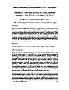
A screen shot of the LESS system is shown in Figure 15. The numbers adjacent to larger dots indicate the actual location of nodes. The dots numbered 0-10 in this example indicate anchor nodes. The numbers next to the smaller dots show the locations computed by the LESS system given the ranging estimates between neighbor nodes. In the actual system, different colors are used to represent actual positions, estimates, and anchor nodes. In the example shown in Figure 15, there are 80 nodes in the network, 11 of which are anchor nodes. The ranging estimates were assumed to be accurate within 0.05 feet. We let the algorithm run until it converges. We define this convergence condition as when the ES runs for 50 consecutive generations without an improvement in the fitness function of 0.01%. The number of generations needed to converge increases with the network size, varying from about 2000 for a 40-node network to approximately 8000 for a 200-node network. The time to run the ES also increases as the network size increases. Consider the mean time to run the ES for G=5000 generations with a population size of µ=50. For a network of 40 nodes, the ES runs in about a half minute, but when the network size reaches 200 total nodes, the time to run the ES is approximately 11 minutes. The experiments were run on a Dell Inspiron 1100 notebook. To evaluate the LESS system, we first tested its accuracy when varying the network size from 40 to 200 nodes. Figure 16 illustrates the results of the experiments. The number of anchor nodes was fixed at 10. Ranging errors (RE) of 0%, 10% and 20% were used. Mean position errors ranged from 1.0 feet with a 40-node network and no ranging error to 8.4 feet with a 160-node network and a 20% ranging error. We implemented an Iterative method similar to [Sa02] in order to compare its position accuracy and power consumption with LESS. Initially, each node in the Iterative
44
method estimated its position being next to one of its neighbor anchor nodes. If a node was neighboring an anchor node, it initially estimated its position at the center of the region. Each node then searches an 8x8 foot region around its current position estimate to find the minimal error to better estimate its position. The new estimate is then broadcast to all of its neighbors. Although computation of a global error in this distributed approach is not feasible, we terminated the Iterative algorithm when it showed no improvement over five consecutive iterations. This stopping condition was determined after preliminary trials showed that if five successive iterations didn't show improvement then further iterations wouldn't improve the solution.
18 Iter RE=0% Iter RE=10% Iter RE=20% LESS RE=0% LESS RE=10% LESS RE=20%
16 Mean error (ft)
14 12 10 8 6 4 2 0 40
80 120 160 Network size (sensors)
200
Figure 16: Position Error Comparison.
As shown in Figure 16, the mean localization errors of the Iterative method are similar to those of LESS for networks of up to 160 sensors. When the network size reached 200 sensors, the LESS system's errors were much smaller than the Iterative
45
technique. The biggest advantage of LESS over the Iterative approach, though, is in power consumption, which is discussed in detail in the next section. It is worth noting that LESS estimates positions for all of the nodes in a 200-node network using only 10 anchor nodes. Recall from [Sa01a] that 45 anchor nodes were needed in a 300-node network to locate 90%, or 270, of the nodes. In Figure 17, we used a network size of 80 nodes and varied the number of anchor nodes between 5 and 13 to study the effect of anchor node density in the LESS system. Again, we used ranging estimates with errors of 0%, 10%, and 20%. As expected, with the increase in the number of anchor points, the mean position error decreases. For an 80node network in a 100x100 foot region we noticed that the mean position error started to level off once a certain number of anchor nodes (11, in this case) were used.
15.0 12.0
RE=0%
Mean Error (ft)
RE=10% RE=20%
9.0 6.0 3.0 0.0 5
7
9
11
Number of Anchor Nodes
Figure 17: Effect of Anchor Node Density with LESS.
46
13
Conclusions and Future Work The localization accuracy produced by the LESS system is quite comparable to that achieved in [Sa01b,SA02, Me01]. LESS does not suffer the power consumption drain from continuous broadcasts of position estimates and refinements, a salient characteristic of most of the algorithms in the literature. For example, in TERRAIN [Sa02] there are 25 iterations of all nodes broadcasting their positions. The LESS system does not require any broadcast messages. In dynamic situations in which nodes are mobile or nodes are added to or removed from the network, this power consumption is further magnified each time the localization process is repeated. The power consumption at the sensor node is critical for typical sensornets, whereas sinks can be maintained, replacing batteries when necessary. In Figure 18, we present a normalized plot comparing the network computation and communication power consumption of LESS and the Iterative method. The total for LESS includes energy spent at the sink. We assume that at sensor nodes a broadcast message consumes energy equivalent to 1000 simple computations, so the ratio of energy consumed in communication vs. computation is 1000:1 [Hl00]. We also assume that the sink node used in LESS is less constrained in terms of processing and power capabilities. The energy savings from the LESS system occurs at the sensor nodes. After the initial ranging phase in LESS, the nodes simply send their neighbor-distance estimates to the sink for localization. The sensor nodes perform no further computations or communication operations. In the Iterative method, each sensor node utilizes its battery by performing both communication and computations during each iteration of the algorithm. In [Me01], for example, each node performs an exhaustive search over a region to find the position
47
with minimal error. This search is repeated for each iteration. 1.0 Iter Total Iter Computation
0.8
LESS Total
Normalized
LESS Computation
0.6 0.4 0.2 0.0 40
80 120 160 Network size (sensors)
200
Figure 18: Power Consumption Comparison.
Although the proposed LESS system uses less energy per sensor node, it suffers from centralization and scalability aspects. One may argue that a centralized approach like LESS will cause unnecessary traffic or congestion near the sink. In many cases, however, it may be necessary for the sink to be aware of all the node positions. Therefore, this traffic will be necessary no matter which technique is used for positioning. One example of the sink needing all node positions is sensor management software in which it is necessary to monitor the status of the network to make sure the required coverage is provided across the entire deployment region. Distributed self-positioning techniques certainly lend themselves well to large sensor networks. The LESS system was more accurate than the distributed approach with a network size of 200 sensors. The main drawback of using LESS for larger networks is the time to perform the localization. Recall that it takes approximately 11 minutes for
48
LESS to localize a 200-node sensor network. When using the LESS approach with largescale networks, one could use multiple sinks to provide the localization to individual clusters, either sequentially or simultaneously, and then combine the solutions. We are currently working on extending our ES based technique to a hierarchical approach to address the scalability issues.
49
CHAPTER V BOUNDING THE LOCALIZATION ERROR Introduction Our main contribution in this chapter is an efficient location discovery algorithm that bounds the localization error. Providing an efficient localization technique is critical in resource-constrained environments that include mobile devices and wireless networked sensors. Our algorithm, based on finding the smallest circle enclosing the intersection of n disks, runs in O(n 2 ) time. We then extend our work to the problem of finding the smallest disk that includes the set of points common to n disks and excluded from the interiors of m
other disks. Finally, we show performance results from the
implementation of our algorithms in which, under some conditions, localization estimates for 500 nodes in a 500x500 ft region can be found with a mean error of one foot and a two-foot mean error bound.
Figure 19: A Disk. A common practice when locating an object is to use estimated distances to
50
known positions, or anchors. Suppose two objects are actually separated by distance d . If the estimate to a position is given by d ' and the possible error for this distance is ±ε , then the object must be located within a disk with radius d '+ ε as shown in Figure 19. If we remove the inside disk with radius d '− ε , we can further say that the object must be located in a washer as illustrated in Figure 20.
Figure 20: A Washer.
If we have distance bounds d '+ ε from n known positions to an object, we know that the object must be located in the intersection of those n disks. We find the smallest circle enclosing this intersection. By choosing the center of this circle as the location estimate, we guarantee that the localization error cannot be larger than the circle's radius. Figure 21 illustrates this process with three disks. In this chapter, we provide algorithms that find the smallest enclosing circle for both the intersection of disks, as well as washers. In addition to providing each step of our location discovery algorithms, we analyze their efficiency and prove their correctness. We first provide an O(n3 ) -time complexity algorithm for finding a location estimate along with a corresponding error bound. We then use a novel approach to
51
improve our technique to O(n 2 ) for the intersection of n disks.
Figure 21: The Smallest Circle Enclosing the Intersection of Three Inclusion Disks.
Listed below are a few advantages of our technique: 1) For every location estimate that is made, a bound on the maximum possible error is also provided. 2) The network just has to be connected. As opposed to many localization techniques, we have no restrictions on the number of neighbors each node must have to other nodes or anchors. 3) The algorithms work in both a centralized, as well as, a distributed environment. 4) This technique applies to both ad hoc mobile computing and wireless sensor networks. 5) The algorithms are independent of the ranging technique used by nodes to estimate distances between neighbors.
52
The remainder of this chapter is organized as follows: First, present definitions and formulate the problems. Then, we provide our solution to the Disk Problem and the Washer Problem. Performance results are given and finally, we make conclusions and talk about future work.
Definitions and Problem Formulation We now present some definitions that are integral to the remainder of the chapter. Given real numbers x, y, r , the disk centered at ( x, y ) with radius r is denoted D = [ x, y, r ] ; in other words, D = {(a, b) : (a − x) 2 + (b − y )2 ≤ r 2 } . The associated circle C = ( x, y, r ) is the boundary of D ; that is C = {(a, b) : (a − x)2 + (b − y ) 2 = r 2 } . Two disks
are called distinct if they either have a different center or a different radius, or both. A diameter of disk D is a line segment joining two points on the associated circle C that passes through the center of D . The two end points of a diameter are called antipodal points. Every point p on the circle C has an antipodal point with respect to C ; the antipodal point of p is the other point of intersection with C of the straight line passing through
p
and
the
Di = [ xi , yi , ri ], i = 1,K , n ,
center we
of
denote
D.
the
Given
n
intersection
pair-wise of
the
distinct n
disks
disks by
Sn := {( x, y ) : ( x, y ) ∈ Di , ∀ i = 1,K , n} . Throughout the chapter, whenever we consider input disks, we always assume they are pair-wise distinct and that they are ordered in non-decreasing order of radius: r1 ≤ r2 ≤ L ≤ rn . A corner point of Sn is a point in Sn where 2 or more input circles intersect. Such a point must be on the boundary of Sn .
53
The first problem that we address is called the Disk Problem: Given centers and radii of n distinct disks, the goal is to find the center and radius of the smallest disk D* = [ x*, y*, r*] that includes the intersection of the n input disks.
The second problem that we address is the Washer Problem. This is similar to the Disk Problem, but the goal is to now find the center and radius of the smallest disk D* = [ x*, y*, r*] that includes the set of points included in all of the input washers.
The Disk Problem As described in the Introduction, our work relies on finding the smallest circle that encloses the intersection of an arbitrary number of input disks. The intersection of the disks is the region in which the object of interest lies. The center of the smallest enclosing circle is our estimate of its location; the radius is our bound on the error. By choosing the center as our estimate, it minimizes the error bound. In this section, we first present an O(n3 ) -time algorithm for finding this smallest circle, prove its correctness, analyze its computational complexity, and then describe how to improve it to O(n2 ) .
O(n3 ) Algorithm for the Disk Problem Input: Centers and radii of n distinct disks: Di = [ xi , yi , ri ], i = 1,K , n , where r1 ≤ r2 ≤ L ≤ rn . Output: Center and radius of the smallest disk D* = [ x*, y*, r*] that includes the intersection Sn of the n input disks.
54
1. [ O(n 2 ) ] Find all pairwise intersection points of the associated circles of the input disks. (There can be at most 2 intersection points for each pair of circles, for a total of n(n −1) intersection points.) 2. [ O(n3 ) ] For each intersection point, determine if this point lies in all of the input disks. Let {(ak , bk )} be the set of these corner points, each of which lies in all of the input disks. (Although this step takes O(n3 ) -time, we will later show that the number of corner points can be reduced to O(n) , and they can be found in O(n 2 ) time.) 3. [ O(n2 ) ] For each corner point that lies on the smallest input circle C1 , check to see if its antipodal point on C1 lies in all of the input disks. If no corner points lie on C1 , then pick any antipodal pair of C1 and check if both points lie in all of the input disks. If any antipodal pair lies in all of the input disks, return C1 as the smallest enclosing circle. Otherwise, proceed to Step 4. 4. [ O(n) ] Return Smallest({(ak , bk )} , the smallest disk containing the O(n) corner points {(ak , bk )} . Megiddo's linear programming algorithm finds the smallest disk containing a set of input points in linear time [Me83]. Next, we explain the steps of the algorithm, improve Step 2 to O(n2 ) , and verify the O(n 2 ) time complexity of the overall algorithm.
55
STEP 1: Finding the Pairwise Intersection Points In [Me83], an O(1) -time complexity algorithm is provided for finding the intersection of two circles. Using this algorithm n(n −1) / 2 times, once for each pair of the n circles, we can find all pairwise intersection points in O(n 2 ) -time.
STEP 2: Finding the Corner Points First we establish that the number of corner points can be reduced to at most 2n − 2 . In doing so, we prove some lemmas that are also useful later.
Theorem 1. The number of corner points is at most 2n − 2 . Proof. We use induction on n . Clearly the theorem is true when n = 2 . Assume it is true when the number of disks is smaller than n . We will show that adding the nth disk adds at most 2 corner points. Recall that r1 ≤ r2 ≤ L ≤ rn . Let Sn −1 be the intersection of the first n −1 disks. As shown in Figure 22, the boundary of Sn −1 consists of a sequence (a1 , b1 ), s1 , (a2 , b2 ), s2 ,K , (ar , br ), sr , (a1 , b1 ) , where each (ak , bk ) is a corner point, and each sk is a circle segment from one of the first n −1 disks. It suffices to show that circle Cn intersects this boundary at most twice.
56
Figure 22: Boundary of Circle Segment. Since Cn coincides with none of the other circles, there is some point p that lies on Cn and outside S n −1 . Starting with p , traverse Cn until the first point p1 where Cn meets Sn −1 (If no such point exists, then we are done). Continue traversing Cn in this same direction, now inside Sn −1 , until the last point p2 before leaving S n −1 (See Figure 23). That is, all points along Cn between and including p1 and p2 are in S n −1 . (Note: it is possible that p1 = p2 .)
Figure 23: Circle Intersecting Segments. Next we will show that the remaining segment of Cn after p2 and before p1 lies completely outside Sn −1 . Since p1 is on the boundary of Sn −1 , p1 must lie on some circle Ce . Similarly, p2 lies on some circle C f . (It could be that Ce = C f .) Since the segment of Cn from p1 to p2 lies in Sn −1 , it must also lie in the intersection of the corresponding
57
disks, De and D f , i.e., De ∩ D f (See Figure 24). Now we show the segment of Cn from p2 to p1 lies outside De ∩ D f , and therefore outside Sn −1 .
Figure 24: Segment of a Circle Intersecting Two Disks.
Let q1 be the second intersection point of Cn and Ce , and let q2 be the second intersection point of Cn and C f . (Note it is possible that q1 = p1 or q2 = p2 , or both.) Traversing Cn , these intersection points are encountered in one of these 2 sequences: p1 , p2 , q1 , q2 or p1 , p2 , q2 , q1 .
Figure 25: Intersection Points of a Circle With Two Disks.
58
Figure 26: Intersection Points of a Circle With Two Disks. In the former case (See Figure 25), the segment of Cn from p2 to q1 is in De − D f ; the segment from q1 to q2 is outside both De and D f ; the segment from q2 to
p1 is in D f − De . Thus, each segment is outside S n −1 , as desired. In the latter case (See Figure 26), the segment of Cn from p2 to q2 is in De − D f ; the segment from q2 to q1 is in De ∩ D f ; the segment from q1 to p1 is in D f − De . Thus, all 4 segments are in De ∪ D f . That is, Cn ⊆ De ∪ D f . This contradicts Lemma 3 below, completing our
proof. W Lemma 1. Let D1 = [ x1 , y1 , r1 ] and D2 = [ x2 , y2 , r2 ] , be 2 disks with r1 ≤ r2 . If C2 has a pair of antipodal points that both lie in D1 , then D2 = D1 Proof. Assume C2 has a pair of antipodal points p and q that both lie in D1 . Then the distance between p and q can be at most the diameter of D1 , which implies 2r2 ≤ 2r1 . Since r1 ≤ r2 , it follows that r1 = r2 . Moreover, p and q must both lie on the boundary of D1 . That is, D2 = D1 , as desired. W
59
Lemma 2. Let D1 = [ x1 , y1 , r1 ] and D2 = [ x2 , y2 , r2 ] , be 2 distinct disks, with r1 ≤ r2 . Then C2 has a pair of antipodal points that both lie outside D1 . Proof. If D1 and D2 are disjoint (See Figure 27(i)), then any pair of antipodal points of C2 lie outside D1 . If D1 ⊆ D2 (See Figure 27(ii)), then, since the disks are distinct, it must be that r1 < r2 , from which it follows that C1 and C2 share at most one common point. Any point of C2 except the antipodal point of this common point can be taken, together with its antipodal point. Finally, assume D1 and D2 intersect but neither is contained in the other (See Figure 27(iii)). Then there is a point p , where C1 and C2 intersect. Let d be the diameter of C2 joining p and its antipodal point q . By Lemma 1, it must be that q ∉ D1 . Now we can rotate d slightly away from p to a diameter of C2 having both ends, which we call d1 and d 2 , not in D1 . W
(i)
(ii) Figure 27: Three Configurations of Two Disks.
60
(iii)
Lemma 3. Let D1 = [ x1 , y1 , r1 ] , D2 = [ x2 , y2 , r2 ] , and D3 = [ x3 , y3 , r3 ] be 3 distinct disks, with r1 ≤ r2 ≤ r3 . Then D3 − ( D1 ∪ D2 ) ≠ ∅ . That is, the largest disk cannot be contained in the union of the other two. Proof. By Lemma 2, there must be a pair d1 , d 2 of antipodal points on C3 that are both excluded from D2 (See Figure 28). If both d1 and d 2 are in D1 , then by Lemma 1, D3 = D1 , a contradiction. Thus, at least one of d1 , d 2 is excluded from both D1 and D2 , as desired. W
Figure 28: Antipodal Points. Now that we have established that Sn has only O(n) corner points, we can hope for a method to find them in less than the O(n3 ) time required by a “brute force” approach that checks whether each intersection point is in every input disk. Any such improvement would improve the overall run time of our Disk algorithm.
61
Finding the Corner Points in O(n2 ) time
For each input circle Ci , order the intersection points with all circles C j :1 ≤ j < i , in a counter-clockwise (increasing-angle) direction. For each intersection point, label that point “+” if the segment from that point in the positive direction lies in both circles meeting at that point, and label it “ − ” otherwise. Traverse the circle in a positive-angle direction until a “+” is followed immediately by a “ − ”. Those two points, which we will call a + − pair, are the only corner points of S j on Ci . This process is illustrated for three circles in Figure 29. If there are two such + − pairs, then we can conclude Ci contributes no corner points. Doing this for all input circles except for the smallest one, C1 , results in an O(n 2 log n) method for finding all the corner points, which is better than O(n3 ) , at least. In this approach, we are finding all of the corner points of S2 , S3 , …, and Sn , and we proved this is at most 2n − 2 total points (Theorem 1). A final step to eliminate those not in Sn , then can be done in O(n 2 ) time.
62
Figure 29: Final Plus/Minus Pair is Found for a Circle. We can modify the above approach to avoid the O(n log n) work required to sort each circle’s intersection points, as follows. While processing circle Ci , keep the current
+ − pair. If the “+” point of the next intersection pair is greater than the current “+” point, then replace the current with the next. If the “ − ” point of the next intersection pair is less than the current “ − ” point, then replace the current with the next. If either the next “+” point is greater than the current “ − ” point or the next “ − ” point is less than the current “+” point, then we can conclude Ci contributes no corner points to Si . If there is an input circle C j :1 ≤ j < i that does not intersect Ci , then there are 2 cases: If C j is contained in Ci , we again conclude Ci contributes no corner points to Si . If Ci and C j are disjoint, the intersection set Sn is empty. This approach requires only O(n) work
for each input circle, leading to an O(n 2 ) method for finding all the corner points.
63
Figure 30: The Processing of the Plus/Minus Pairs. This process of using the plus/minus pairs to find the contributing corner points of Ci is illustrated in Figure 30. With two circles, there is one plus/minus pair indicating the two corner points of Ci . When a third circle is added, the "-" point is replaced. The "+" point is replaced when the fourth circle is added, and the final plus/minus pair represents the two corner points contributed by Ci . We leave as an open question whether this can be improved to O(n log n) , or even O(n) .
STEPS 3 and 4: Checking the Antipodal of each Corner Point If a diameter of D1 is contained in Sn , then D1 is the solution to the Disk problem. Otherwise, the solution is the smallest enclosing disk containing all of the corner points. This smallest disk can be obtained by Megiddo’s linear-time algorithm
64
[Me83]. The checks are made in Steps 3 and 4 of the algorithm and their validity can be established by the following lemmas and Theorem.
Lemma 4. If some pair of antipodal points of input circle C j both lie in Sn , then it must be that j = 1 . Moreover, in this case, the input disk D1 is the smallest disk containing Sn . That is, D1 = D * . Proof. Suppose some pair of antipodal points of C j lie in Sn (See Figure 31). Then they also lie in C1 , implying, by Lemma 1, that D j = D1 . Since the disks are distinct, it follows that j = 1 , as desired. Now r* ≤ r1 , and since the pair of antipodal points of C1 lie in Sn , they lie in D * , implying again by Lemma 1 that D1 = D * . W
Figure 31: If Antipodal Point Lies in Intersection, Then Solution is Smallest Disk.
Lemma 5. If some pair of antipodal points of input circle C1 both lie in Sn , then either D1 ⊆ S n , in which case all antipodal pairs of points of C1 lie in Sn , or there is some corner point (ak , bk ) that lies on C1 and the antipodal point of (ak , bk ) on C1 lies in Sn .
65
Proof. Assume some pair p and q of antipodal points of C1 lie in Sn . If D1 ⊆ S n , then we are done, so assume not. Now since D1 ⊄ S n , it must be that C1 ⊄ S n , and since C1 contains at least one point of Sn , C1 must contain a corner point. Let d be a diameter of D1 joining p and q . Rotate d about the center of D1 , until the first time one of its ends hit a corner point. The antipodal point of that corner point lies in Sn , as desired. W Theorem 2. If every corner point on input circle C1 has its antipodal point lying outside Sn and D1 ⊄ Sn , then D * is the smallest disk containing all of the corner points. Proof. Assume every corner point on input circle C1 has its antipodal point lying outside Sn and D1 ⊄ Sn . Let D ' = [ x ', y ', r '] be the smallest disk containing all of the corner points. It suffices to show that S n ⊆ D ' . Suppose not. Then the boundary of Sn must contain some point outside D ' . The boundary of Sn consists of a sequence (a1 , b1 ), s1 , (a2 , b2 ), s2 ,K , (al , bl ), sl , (a1 , b1 ) , where each (ak , bk ) is a corner point, and each sk is a circle segment from one of the n input disks. Since D ' contains all the corner points, there must be some circle segment s j that leaves and then re-enters D ' (See Figure 32). Since D j contains all the corner points, it must be that r ' ≤ rj . By Lemma 2, C j has a pair of antipodal points that lie outside D ' . Since C j and C ' meet at most
twice, that pair of antipodal points must be on the segment of s j that leaves and then reenters D ' . But then, those antipodal points are in Sn , implying, by Lemma 4, that j = 1 .
66
Since we have a pair of antipodal points of C1 in Sn , Lemma 5 implies either D1 ⊆ S n or a corner point on C1 and its antipodal point lie in Sn . This contradicts our hypothesis. W
Figure 32: The Intersection of Solution Segments with a Disk. Next we discuss the computational aspects of Steps 3 and 4. Given the center of a circle ( xc , yc ) and a point on that circle ( x p , y p ) , the antipodal point ( xa , ya ) can be found as xa = xc + ( xc − x p ) and ya = yc + ( yc − y p ) . To check if an antipodal point ( xa , ya ) lies in all n input disks Ci = ( xi , yi , ri ) , you would simply examine if ( xa − xi ) 2 + ( ya − yi ) 2 ≤ ri 2 is true for each i = 1,..., n . To test whether each of the O(n) corner points of C1 has an antipodal point in each of the n input disks exhaustively would require O(n 2 ) work. Perhaps we can do better. Can we improve this step to O(n) ? It is true that there can be O(n) corner points on the smallest circle. Therefore, we would like to be able to check to see if the antipodal point of each is in the intersection, without having to explicitly check its inclusion in all the input disks. By using the Disk Method to find D * , the point ( x*, y*) is used to estimate an object's location and the localization error is bounded by r * . 67
The Washer Problem We now consider the Washer Problem. If we can place a minimum bound, d '− ε , on the distance between an object and an anchor, we are sure that the object will lie outside of the disk centered at the anchor and having a radius of d '− ε . This forms the basis of the Washer Problem detailed below:
O(n3 ) Algorithm for the Washer Problem Input: Centers and radii of n (inclusion) disks: Di = [ xi , yi , ri ], i = 1,K , n , where r1 ≤ r2 ≤ L ≤ rn , and m (exclusion) disks:
D 'i = [ x 'i , y 'i , r 'i ] ,
i = 1,K , m , where
r '1 ≤ r '2 ≤ L ≤ r 'm . All input disks are pair-wise distinct. Output: Center and radius of the smallest disk D* = [ x*, y*, r*] that includes the set
of
points
S = I −E ,
where
I = (D1 ∩ D2 ∩ L ∩ Dn )
and
E = ( D '1 − C '1 ) ∪ ( D '2 − C '2 ) ∪ L ∪ ( D 'm − C 'm ) . That is, S is the set of points included in all the inclusion disks and excluded from the interiors of all the exclusion disks. In Figure 33, the set S is indicated by the shaded region. In the following algorithm, we assume that the number of inclusion disks and exclusion disks are approximately the same ( m ≤ 2n ). Therefore, O(n) = O(m) .
68
Figure 33: The Washer Problem. 1. [ O(n 2 ) ] Find all pairwise intersection points of the associated circles of the n inclusion disks and m exclusion disks. There can be at most 2 intersection points for each pair of circles, for a total of (m + n)(m + n −1) / 2 intersection points. 2. [ O(n3 ) ] For each intersection point, determine if this point lies in all of the inclusion disks and outside all of the exclusion disks. Let {(ak , bk )} be the set of these corner points. 3. [ O(n 2 ) ] For each of the O(n) corner points that lies on the smallest input circle C1 , check to see if its antipodal point on C1 lies in all of the inclusion disks and outside all of the exclusion disks. If any such antipodal passes this check, return C1 as the smallest enclosing circle. Otherwise, proceed to Step number 4.
69
4. [ O(n 2 ) ] Return Smallest({(ak , bk )} , the smallest disk containing all of the corner points {(ak , bk )} using Meggido’s linear-time linear programming algorithm [Me83]. Note that corner points = O(n 2 ) .
Figure 34: The Intersected Region is Broken into Multiple Pieces. As shown in Figure 34, it is possible that the inclusion disks and exclusion disks will break the set S into multiple disjoint pieces. Because of this, our proof of the O(n) bound on the number of corner points does not carry over to the washer case. We leave open the questions of whether the number of corner points is less than O(n 2 ) and whether they can be found in less than O(n3 ) time. We can, however, still establish the validity of Step 4, which results in our O(n3 ) algorithm above. The proof is similar to that of the Disk Method. As with the Disk Method, the smallest enclosing circle D * is used in the localization problem by estimating an object's location at ( x*, y*) with an error bound of r * .
70
Performance Results A program was developed to implement our algorithms in order to simulate the localization process under varying conditions. We used the Delphi programming environment because its excellent graphics capabilities make it ideal for illustrating visually the disks and washers used in our technique. Figure 35 shows a screen shot of the system when localizing a network of 100 nodes. The map on the left side of the system displays the actual position and the location estimate for each non-anchor node. For each non-anchor node, the error bound circle is displayed centered at the node's position estimate. The table at the right of the system screen displays minimum, maximum and average values for both the actual error and error bound for non-anchor nodes in 10 different random networks.
Figure 35: Screen Shot of Network Localization System. The system assumes a node can estimate the distance between itself and each of its neighbors. Although more accurate ranging techniques will produce smaller localization errors, our approach is not dependent on any one ranging technique. The
71
system also assumes that a small subset of the nodes, anchors, are aware of their location. Anchor nodes are either physically placed at known positions or they are equipped with a positioning technology such as GPS. Finally, for simplicity, the system assumes: (1) signals are omni directional and symmetric, (2) all nodes have the same transmission range, and (3) every node has at least one neighbor and the network is connected. In our simulation experiments, we randomly deployed 500 sensor nodes over a 250,000 ft2 region (500 x 500 foot square). The anchor nodes were placed in a mesh configuration. When running trials based on radio transmission, the radio range was assumed to be 100 feet. This range was based on experimental results using secondgeneration MICA2 motes [Cr05]. When calculating perceived distance between 2 nodes, a random normally distributed error e ∈ [−ε, ε] is generated and added to the actual distance d . The resulting perceived distance d ' = d + e is thus within d ± ε , where ε is the maximum ranging error. Next, to ensure a correct bound, the disk radius of d '+ ε is used in the algorithm. When we use the Washer method, the inner disk's radius is taken to be d '− ε . By having each node find an upper bound on its multi-hop distance to every anchor node, we can localize the nodes using any or all of the anchors, not just the neighboring ones. To accomplish this, each anchor node broadcasts its position to initialize the localization process. All other nodes will then broadcast these anchor positions as well as their maximum distance estimate to each anchor. After several iterations of this process, each node will now have an upper bound on the distance to every anchor node in the network. These upper bounds are used as the circles in the Disk method. If a node is a neighbor to an anchor node, it uses the distance estimate d '− ε as
72
the radius of the washer’s inner circle. If the node is not a neighbor to an anchor, the best we can do is to use the maximum transmission range (e.g., 100 feet) as the washer’s inner circle. When using the exclusion disks in addition to the inclusion disks, the size of the smallest enclosing circle is sometimes reduced (see Figure 33). A node uses the distances, d '± ε , from multiple anchors to form the washers for localization. Each node chooses its closest anchors when selecting anchors to be used. In our experiments, we varied the number of anchors, or washers, used in the localization calculations from 2 to 10. A 500-node network was generated and a 6x6 mesh of 36 anchors was used. An ε of 10 feet was used for the maximum ranging error. 40 35
Mean Error (feet)
30 25 20 15 10 5 0 2
3
4 5 6 7 8 Anchors Used by Each Node
9
10
Disk - Actual Error Disk - Error Bound Washer - Actual Error Washer - Error Bound
Figure 36: Comparison of Disk and Washer Methods.
73
Figure 36 shows averaged results of localizing the 500-node network. The Washer method had a slightly smaller mean actual localization error than Disk. When using 10 anchors, for example, the actual error of the Disk method was 5.29 feet and Washer was 4.60 feet. When looking at the bound on the localization error, recall that it is the radius of the smallest enclosing circle of the intersecting washers. The Washer method gave a slightly tighter bound on the error than Disk. The error bound for Disk was 14.07 feet and Washer was 10.96 feet. First, note that the average actual error is quite small on the order of ε / 2 , or half of the maximum ranging error. This is a bit surprising since the actual error is in 2 dimensions, whereas the ranging error is a 1-dimensional measure. Second, note that our error bound is also generally quite small, being approximately twice the actual error. In Figure 37, we show how increasing the density of the anchors affects the localization error. Keeping constant the 500x500 feet region and the 100-foot radio range, we ran experiments using a 500-node network and varied the mesh sizes of anchors to be 16, 36, 64, and 100. As one might expect, the networks with more anchors per square foot produced lower errors. Having more anchors as neighbors provided smaller inclusion disks compared to the disks resulting from multi-hop paths. With 10 anchors contributing, the mean actual error for 16, 36, 64, and 100 anchors were 7.07, 5.29, 4.08, and 3.63 feet, respectively. The mean error bounds for these same networks were 20.19, 14.07, 11.33, and 10.58 feet.
74
60
Mean Error (feet)
50
40
30
20
10
0 2
3
4
5
6
7
8
9
10
Anchors Used by Each Node 16 Anchors - Actual Error 16 Anchors - Error Bound 36 Anchors - Actual Error 36 Anchors - Error Bound 64 Anchors - Actual Error 64 Anchors - Error Bound 100 Anchors - Actual Error 100 Anchors - Error Bound
Figure 37: Effect of Anchor Density on Localization Error.
In most cases, increasing the number of anchors, or washers, used for localization improved the results. This increasing of anchors used eventually plateaus. As you can see from Figures 36 and 37, this plateau appears to occur at about 4 or 5 anchors. As more anchors are used, however, this increases the number of computations a node must perform to localize. This can have an effect on energy utilization of a node, which in turn, affects the lifetime of a wireless sensor network. Therefore, even though we showed the efficiency for the Disk and Washer algorithms to be O(n 2 ) and O(n3 ) , respectively, it appears that using values of n larger than 4 or 5 will require more work but add no significant degree of accuracy.
75
As mentioned previously, our technique does not rely on any specific ranging technique. In Figure 38, we show how the accuracy of the ranging method affects the localization error. We are using disks with radius d '+ ε based on distance estimates using values of 1, 10, and 30 feet for the maximum ranging error ε . In these experiments when 10 inclusion disks were used, a maximum ranging error ε of 1, 10, and 30 feet produced mean actual errors of 1.05, 5.29, and 12.66 feet respectively. The error bounds were 2.18, 14.07, and 31.72 feet. As one would expect, the smaller values of ε produce better localization accuracy. When ε of 30 feet was used, the error bound was approximately ε and the actual errors were less than ε / 2 . 60
50
Mean Error (feet)
40
30
20
10
0 2
3
4 5 6 7 8 Anchors Used by Each Node
9
10
1 foot - Actual Error 1 foot - Error Bound 10 feet - Actual Error 10 feet - Error Bound 30 feet - Actual Error 30 feet - Error Bound
Figure 38: Varying the Maximum Ranging Error.
76
In all of the previous examples, we deployed the anchors in a mesh configuration. We decided to consider an anchor configuration that places all of the anchors along the perimeter of the region. The perimeter configuration might make sense when placing anchors in a region was difficult (military, volcano, heavy foliage, etc.). We used a 500node network of 16 anchors and compared the accuracy of a 4x4 mesh of anchors versus a perimeter arrangement with 5 anchors along each side of the region. In the perimeter scenario, over half of the nodes did not have any neighbors that were anchors. As illustrated in Figure 39, when only a few washers were used in the computation, the perimeter configuration produced much larger errors than the mesh configuration. As more washers contributed to the localization, however, the two configurations produced comparable results. With 10 anchors used, for example, the mean actual error was 7.76 feet for mesh and 9.31 feet for perimeter. The mean error bounds for mesh and perimeter were 21.87 and 23.97 feet, respectively. It is worth noting that when more anchors are used in the perimeter configuration, it tended to give larger errors. This was because a node would choose all of its neighboring anchors from the same boundary. The resulting smallest enclosing circle would thus be along that border instead of towards the interior of the region where the node actually lies. When using perimeter, one could address this by choosing anchors from different boundaries.
77
100 90 80
Mean Error (feet)
70 60 50 40 30 20 10 0 2
3
4
5
6
7
8
9
10
Anchors Used by Each Node Mesh - Actual Error Mesh - Error Bound Perimeter - Actual Error Perimeter - Error Bound
Figure 39: Comparing Different Anchor Configurations.
Conclusions and Future Work We have shown that we can bound the error on the localization of a node by finding the smallest enclosing circle that covers the intersection of multiple disks. The disks are constructed by taking the maximum distances d '+ ε from anchor nodes as the disk radius and use the anchor's position as the disk center. We use the center of the smallest enclosing circle as the location estimate of the node and the radius of the circle as the error bound. We provided a novel O(n 2 ) algorithm for finding this location estimate and error
78
bound, where n is the number of anchors used by each node. We believe that Step 2 of our Disk algorithm in which we compute the corner points can be improved and we leave this problem as part of our future work. We extended our Disk technique to what we called the Washer method. Based on the distance to anchors, the washers are constructed using the inclusion disks as the exterior circle and exclusion disks with radius d '− ε as the inner circle. We provided an O(n3 ) algorithm for solving the Washer problem and are hopeful that we can improve on this efficiency in the future. Providing a location estimate for a device is more meaningful if you can say something about the confidence that you have in the estimate. In our technique, we are saying that there must be a bound on the ranging estimate between two neighboring devices. For example, we say that there exists some maximum error ε in which distance estimates between the two devices will always fall into the range d ± ε , where d is the actual distance between the devices. In some conditions, the ranging estimate may be very accurate most of the time, but occasionally produces a large error. This type of environment would yield a large value of ε and, as illustrated in Figure 38, a bigger localization error. To address this, we must extend our work so that confidence intervals can be used in conjunction with the location estimates and error bounds. Chapter VI considers this extension. It is important to note that our technique does not depend on the number of nodes in the network or the percentage of nodes that need to be anchors. Given a region and a set of anchor nodes in that region, our system will produce the same accuracy and amount of work per device for locating 10,000 devices as it does for locating one device. The
79
important factors in the localization accuracy, as reported in the previous section, are anchor density, maximum ranging error, number of anchors used in the computations, and anchor configuration.
80
CHAPTER VI LOCALIZATION WITH CONFIDENCE Introduction In the previous chapter, we introduced a technique that associates an error bound with each location estimate. It assumed that we could bound the error on ranging estimates between neighbors. In some cases, it may be more practical to use a distribution of the ranging error instead of a bound. In this chapter, we introduce a location discovery algorithm that provides an error bound as well as a confidence level associated with each location estimate. Our technique is independent of the ranging technique used to estimate distances between neighbors and performs in environments with noisy range measurements. We provide a versatile framework that allows users to perform localization queries based on the accuracy and certainty a situation requires. Finally, we show performance results from the implementation of our algorithms that confirm the confidence levels that our system claims. For example, in one scenario, our system estimated node locations within 3 feet in a 250,000-ft2 region with a 0.7-confidence level. In a 500-node network, 87% of the nodes were actually within this 3-foot bound. Many localization techniques in the wireless sensor network literature only provide coordinates for a subset of the nodes. For example, in a discussion of a localization paper [Mo04], the requirements of the technique allowed 77% of the nodes to be localized for a sample network. What happens to these other nodes? In a 1000-node network, for example, there may be 230 sensors in which the coordinates are not found. If one of these unknown sensors observes an event of interest (pollution detected, enemy vehicle identified, etc.), we need to know the location of this sensor. If geographic
81
routing is to be used, can any of these 230 sensors without a location participate in the routing process? Many localization algorithms put stringent conditions on the topology of the network in order to identify a node's location [Mo04,Go04,Go05]. Instead of simply ignoring the nodes that do not meet these conditions, we contend that it still possible to identify their locations, but with a lesser degree of certainty. Instead of just saying that a "node cannot be localized", can't we say something about that node's location? If we make some basic assumptions about the network connectivity and a node's ability to estimate distances to each of its neighbors, we should be able to provide a location estimate for all of the nodes in a network. Some of the estimates may not be very precise, but we still should be able to provide an error bound and a confidence level associated with each location estimate. In chapter V, we provided a novel O(n 2 ) -time algorithm that finds the smallest circle enclosing the intersection of n disks. This allows us to provide an error bound on localization estimates when the error on the distance estimates between neighbors is bounded. In this chapter, we assume that we know the distribution for ranging estimates between neighbors. Based on this distribution, we use the algorithm from chapter V to provide location estimates for nodes that have both error bounds and confidence levels associated with them. This chapter addresses the problem of finding the location of all the nodes in a network given the location of a small subset of the nodes and estimates of the relative distances between pairs of nodes (i.e., relative distances are not known exactly). Our
82
solution is in the form of a point estimate along with an error bound and an associated confidence level. The remainder of this chapter is organized as follows: First, we provide our technique for locating a single object with confidence. We describe localization queries and provide a general framework for localizing an entire network using confidence levels. Performance results are given and finally, we make conclusions and talk about future work.
Locating an Object with Confidence In this section, we present a technique for locating a single object using confidence intervals. Suppose we use a ranging technique to estimate the distance to an object from a given point (x,y) . Let's assume that the ranging error has a normal distribution with a mean µ = 0 and a standard deviation σ .
Figure 40: Location Estimate from a Single Point.
83
It is important to note that although we are assuming the error to be normally distributed, our method doesn’t require that. Moreover, our method could handle the situation where the error has any known distribution, even if the distribution depends on the distance (higher distance, larger sigma, for example). If there is a ranging estimate of e , then there is a 0.5 probability that estimate was too large and a 0.5 probability the estimate was too small. Therefore, we could say with a confidence of 0.5 that the object is within the disk ( x, y, e) of radius e and center ( x, y ) (see Figure 40). Further, we could say with a confidence 1 − α that the object is within the disk (x,y,e+zα σ ) , where zα is the value of the Standard Normal variable with P( Z < zα ) = 1 − α [Di05]. If the ranging error X has any arbitrary known distribution, then we would replace e + zα σ by e + xα , where xα is the value of the random variable X with P ( X < xα ) = 1 − α . It is even possible to have the distribution of X depend on e.
Figure 41: The Intersection of Three Disks.
84
In Figure 41, we look at the disks that are formed when estimating the distances between an object and three known points. Table 4 details, for each disk, the radius and the probability that the object is inside that disk.
Disk
Radius
D1
e1 + zα 1σ 1
Probability the object is inside the disk 1 − α1
D2
e2 + zα 2σ 2
1 −α 2
D3 e3 + zα 3σ 3 1 −α 3 Table 4: Confidence Properties of Three Disks. The intersection of the three disks is denoted in Figure 41 by S . Using the probabilities from Table 4 we can calculate the probability that the object is located within the region S to be P = (1 − α 1 )(1 − α 2 )(1 − α 3 ) . To compute P by multiplying the three individual probabilities, we are assuming the three ranging events are independent. In chapter V, we provided an O(n 2 ) -time algorithm that finds the smallest circle enclosing the intersection of n disks. The solution, a circle given by ( x*, y*, r*) , provided a point estimate ( x*, y*) for the location with an error bound of r * . Using this algorithm on the disks in Figure 41, we find the smallest circle enclosing the region S . This gives us a location estimate ( x*, y*) and we then say that we are P confident that this estimate is within r * of the object's actual location.
85
Localization Queries Given the approach detailed above, there are several queries that one may pose when trying to locate an object based on three anchor nodes and their distance estimates to the object: 1) A query of Localize ( s, p ) is asking to find a location estimate ( x*, y*) for the object s and the minimum error bound r * with confidence of at least p . For example, we may wish to know the location of an object and the smallest error bound so that we are 90% confident that the estimate is within that range. 2) A query of Localize ( s, r*) is asking to find a location estimate ( x*, y*) for the object s and the maximum confidence level p such that the location estimate has an error bound of r * . For example, we may wish to know the location of an object and the maximum confidence level for which we are sure that the estimate is within 5 feet. 3) A query of Localize ( s, p, r*) looks to find a location estimate ( x*, y*) for the object s such that we have a confidence of p that the estimate is within r * . For example, we might want to find the location of an object so that we are 95% confident that the location estimate is within 10 feet of its actual position. It is possible that no such solution exists. We have developed a system that will perform the queries above. A screenshot is shown in Figure 42. The system assumes that each of the three anchor nodes estimates the distance between itself and an object to be located. We assume that the ranging errors are independent and have normal distributions with a mean µ = 0 and a standard deviation σ . This system is discussed in more detail in the Performance Results section.
86
Figure 42: The Localization with Confidence System.
Let us consider an example. Assuming a probability of 0.5 for an object to be located inside a disk of radius equal to the initial ranging estimate, the probability that the object is located within the intersection of three disks, provided such an intersection actually exists, is p = (0.5)(0.5)(0.5) = 0.125 . Since a confidence level of 12.5% is of little use, we can increase this probability by increasing the radii of the disks. Increasing a disk's radius from e to e + zα σ , for example would increase the probability from 0.5 to 1 − α that the object was in the disk. Recall that zα is the value of the Standard Normal variable such that P ( Z < zα ) = 1 − α . Our system works by finding the values for zα 1 , zα 2 , and zα 3 such that the product P = (1 − α 1 )(1 − α 2 )(1 − α 3 ) is at least the given probability value and the solution
87
r * is minimal. With 31 different values in the Standard Normal table rounded to 2
significant digits, the size of the search space when using 3 anchor nodes is 313 = 29,791 . Our system examines a small subset of this search space by beginning with each zα = 3.0 and decrementing by 0.1 the zα that makes the most significant impact on the solution. We define this condition as the largest ratio
∆r , ∆p
where ∆r is the change in the
error bound r * and ∆p is the change in the product of the probabilities. Recall that decreasing a zα will reduce the confidence level but may also decrease the error bound r*.
In some instances, we would like to know the locations of all of the nodes in a wireless sensor network. Network management software, for example, may need to know the locations of all nodes in order to ensure that the proper coverage of a region is maintained. Next, we will construct a general framework for the problem of localizing an entire network with confidence. The technique will associate both an error bound and a confidence level with each node's location estimate.
Localizing an Entire Network with Confidence We have two techniques that allow us to localize the nodes which do not have three anchor nodes as neighbors: (1) Take the nodes that have been localized using three anchors and then make them anchors, and (2) Estimate distances to non-neighboring anchors by using multi-hop paths. The first technique works iteratively localizing nodes, though, errors keep compounding. Another advantage of the second technique is that it
88
will allow every node in the network to be localized. Therefore, for this work, we proceed using the second approach. Figure 43 illustrates how the location estimates can be computed using multi-hop paths as estimates to non-neighboring anchor nodes. Anchor nodes are labeled A1, A2,..., A6 and the sensor nodes to be localized are labeled as s1, s 2,..., s10 . In the
figure, the location for node s 2 is being computed. This node has one neighboring anchor node, A2 , and two non-neighboring anchor nodes, A1 and A5 , that are both two hops away.
Figure 43: Localizing a Node Using Multi-hop Paths. To get an accurate location estimate by using the Disk method from chapter V, at least three ranging estimates from anchors are needed in order to form the three disks centered at those anchors. The disk centered at A2 will use the ranging estimate d ( s 2, A2) as its radius. Similar to the DV-distance technique used in [Ni01], the disks
centered at A1 and A5 will simply use the sum of the ranging estimates as their radii.
89
For example, the radius for the disk centered at A1 will be d ( A1, s1) + d ( s1, s 2) . As you can see from the figure, the multi-hop estimate between A1 and s 2 will be fairly accurate since s1 lies close to the straight line connecting A1 and s 2 . The estimate between A5 and s 2 , however, will probably be too large since s 7 lies further away from the straight line connecting A5 and s 2 . How this over-estimation affects the performance of the system will be discussed in the Performance Results section. Each additional hop adds a new factor to the probability that the node is within the intersected region. For example, in Figure 43, the probability that node s 2 is within the disk centered at A1 with radius d ( A1, s1) + d ( s1, s 2) is at least the product of the two individual
probabilities
P ( s1 is inside Disk(A1, d ( A1, s1)))
and
P ( s 2 is inside Disk(s1, d ( s1, s 2))) . Since two of the anchors are two-hops away and one
is a neighbor, the probability that s 2 is within the intersected region, therefore, is the product of five probabilities. As discussed earlier, increasing the radii of each of these disks increases the corresponding probabilities. The technique described above finds location estimates with associated confidence levels and error bounds for every node in the network. Let’s assume a set V of sensor nodes is connected. That is, every node in V is able to send a message via multi-hop routing to every other node in the network. Also, assume that every node has a symmetric, omni-directional transceiver with a fixed transmission distance, r . Each node, si ∈ V , has a set of neighbors, N i , such that s j ∈ N i ⇔ d ( si s j ) ≤ r . Associated with each pair of neighbors is a distance estimate eij ≤ r .
90
Figure 44: A Sensor Network with Location Estimates. Figure 44 represents a set V of nine sensor nodes ( S 0, S1,..., S 8) . Associated with each location estimate xˆi , yˆi , there is a vector of error-confidence pairs that could be obtained by the method described above. For example, with node S 0 , there is a 90% confidence that it is within 2 feet of the position (10,10) and a 100% confidence that it is within 5 feet of position (10,10) . Nodes S1 , S 2 , and S 8 all have an error-confidence pair of (0,1.0) . This means that we are completely confident in their location estimates. These nodes were probably placed in known positions, use a positioning technology such as GPS, or are being used as reference points for the localization. Now we take a look at the definitions of the localization queries that were discussed earlier and examine how each of these queries types could be posed to the network illustrated in Figure 44. 1) A query of Localize (V , p ) returns for every si ∈ V , an estimate ( xˆi , yˆi , εi , pi ) , where pi ≥ p . In this situation, the request is made to provide location estimates with
91
minimum associated error bounds based on confidence criteria p for every node in the network. Table 5 shows example queries that might be posed along with their returned output. In the first query, a value of p = 0.9 is given, but no error bound is provided. The question posed here is "Give me the location estimates for all nodes and the minimum error bounds that would be associated if we wanted to be at least 90% confident in each estimate". The result of the query is the coordinates of all nodes that satisfy the constraint along with the associated error bounds. 2) A query of Localize (V , ε) returns for every si ∈ V , an estimate ( xˆi , yˆi , εi , pi ) , where εi ≤ ε . In this situation, the request is made to provide location estimates with maximum associated confidence measures based on error bound criterion ε for every node in the network. In the second query shown in Table 5, a value of ε = 2 is passed with the localization query, but no confidence value is provided. The question posed is "Give me the location estimates for all nodes and the maximum confidence that we have for each estimate to be within 2 feet". The result of the query is the coordinates of all nodes along with the associated confidence values.
92
Query
Result S0(10,10,2), S1(40,0,0), S2(0,20,0), S3(30,20,5), 1) Localize (V, p=0.9) S4(0,50,5), S5(40,50,5), S6(10,70,2), S7(50,70,5), S8(20,100,0) S0(10,10,0.9), S1(40,0,1.0), S2(0,20,1.0), S3(30,20,0.8), S4(0,50,0.7), S5(40,50,0.7), 2) Localize (V, ε=2) S6(10,70,0.9), S7(50,70,0.8), S8(20,100,1.0) S0(10,10), S1(40,0), S2(0,20), S3(30,20), 3) Localize (V, ε=2, p=0.8) S6(10,70), S7(50,70), S8(20,100) Table 5: Example Localization Queries and Their Results. 3) A query of Localize (V , ε, p ) returns a set of nodes L ⊆ V , such that for every si ∈ L , there exists an estimate ( xˆi , yˆi , εi , pi ) , where pi ≥ p , and εi ≤ ε . In this case, we are saying provide location estimates for only the nodes in the network that satisfy the criteria of error bound ε and confidence level p . In the final query, values of ε=2 and p = 0.8 were provided. The question posed is "Give me the locations of all nodes in which we are at least 80% confident that the estimates are within 2 feet". The result of the query is simply the coordinates of those nodes that satisfy the criteria.
Performance Results A program was developed to implement our algorithms in order to simulate the localization process under varying conditions. We used the Delphi programming environment because its excellent graphics capabilities make it ideal for illustrating visually the disks used in our technique.
93
The system assumes a node can estimate the distance between itself and each of its neighbors. Although more accurate ranging techniques will produce smaller localization errors, our approach is not dependent on any one ranging technique. The system also assumes that a small subset of the nodes, anchors, are aware of their location. Anchor nodes are either physically placed at known positions or they are equipped with a positioning technology such as GPS. Finally, for simplicity, the system assumes: (1) signals are omni-directional and symmetric, (2) all nodes have the same transmission range, and (3) every node has at least one neighbor and the network is connected. In our simulation experiments, we randomly deployed 500 sensor nodes over a 250,000-ft2 region (500 x 500 foot square). The anchor nodes were placed in a mesh configuration. When running trials based on radio transmission, the radio range was assumed to be 100 feet. This range was based on experimental results using secondgeneration MICA2 motes [Cr05]. When calculating perceived distance between 2 nodes, a random normally distributed error with mean µ = 0 is generated and added to the actual distance d . The standard deviation σ depends on the ranging technique used. The user of the system can vary σ to determine how using different ranging techniques will impact the accuracy of the location estimates and their associated confidence levels. By having each node find a multi-hop distance to every anchor node, we can localize the nodes using any or all of the anchors, not just the neighboring ones. To accomplish this, each anchor node broadcasts its position to initialize the localization process. All other nodes then broadcast the positions of their anchor neighbors, together with their distance estimate to each of those anchors. After several iterations of this
94
process, each node will now have an estimate on the distance to every anchor node in the network. These estimates are used as radii of the circles in the Disk method described in chapter V.
Figure 45: Examining Percentage of Nodes within the Error Bound with Varying Confidence Level and Sigma.
To verify that the confidence levels that our system was claiming, we needed to examine how many of the node location estimates were actually within their error bounds. For example, if we were locating 400 sensors with a 90% confidence level, we would expect that approximately 360 of those sensors are within their respective error bounds. To check if a node is within its error bound, we simply compute the distance between the node's actual location and its estimate and compare the this distance to the error bound. We first verify the confidence levels by considering the case in which every node had at least three anchors as neighbors. We used a network of 500 nodes, 49 of which
95
were a 7x7 mesh of anchors. The non-anchors were uniformly distributed over the 250,000-ft2 region. We used confidence intervals of 0.7, 0.8, 0.9, 0.95, and 0.99. To observe how the ranging accuracy affected the technique, we varied the values of σ as 1, 5, and 10 feet. Figure 45 shows averaged results of localizing the 500-node network. As you can see, in all cases the percentage of nodes that were within their error bound was higher than the user-prescribed confidence level. For example, when a confidence level of 0.9 was used, the percentage of nodes within their error bounds was 98.1%, 96.9%, and 95.2%, respectively, for σ values of 1, 5, and 10. In all cases, when a 0.99 confidence level was chosen, the percentage of nodes that were actually within their error bound was 99.9%. Figure 46 shows the accuracy obtained when localizing the 500-node network using the parameters detailed above. Both the actual errors and the error bounds are reported. As mentioned previously, our technique does not rely on any specific ranging technique. Figure 46 shows how the accuracy of the ranging method affects the localization error. As discussed in the previous section, increasing the desired confidence level also increases the localization error. With the most accurate ranging technique ( σ =1) and a confidence level of 0.7, the system produced a mean actual error of 1.90 feet and a mean error bound of 3.16 feet. With a confidence level of 0.99, the mean actual error was 2.94 feet and the mean error bound was 6.39 feet.
96
All Nodes have 3 Anchors as Neighbors 45 40
Localization Error (feet)
35 30 25 20 15 10 5 0 0.7
0.8
0.9
0.95
0.99
Confidence Level Actual Error, sigma=1
Error Bound, sigma=1
Actual Error, sigma=5
Error Bound, sigma=5
Actual Error, sigma=10
Error Bound, sigma=10
Figure 46: Effect of Ranging Accuracy on Localization Error. When a less accurate ranging technique ( σ =10) was used with the 0.7 confidence level, the mean actual error was 10.97 feet and a mean error bound was 18.42 feet. At the .99 confidence level, the mean actual error was 11.68 feet and the mean error bound was 38.71 feet. As you can see from the Figure 46 graph, as the confidence levels increase, the error bounds also increase as expected. The actual errors, however, only increase slightly when larger confidence levels are chosen. Figure 46 illustrates how both the ranging accuracy and the required confidence level affect the localization errors. A third factor that affects the localization accuracy is the number of anchors used for a fixed sized region. In Figure 47, we show how increasing the density of the anchors affects the percentage of nodes that are within their error bounds and in Figure 48 we show how it affects the localization error. Keeping constant the 500x500 feet region and the 100-foot radio range, we ran
97
experiments using a 500-node network and varied the mesh size of anchors to be 16, 25, 36, and 49. Recall that in the previous simulation, an anchor population of 49 was used. In that case, every node to be localized had three neighboring anchor nodes. By using more than 49 anchors, therefore, the gain in accuracy, as well as percentage of nodes within their error bound, is very minimal. As the number of anchors is reduced, however, the nodes to be located are forced to use more multi-hop paths as distance estimates to their anchors. As one might expect, the networks with more anchors per square foot produced lower errors. The networks with the smallest anchor densities, however, actually had the highest percentage of the nodes within their error bounds. This result will be explained shortly. In all cases, we chose a ranging technique that had a standard deviation of σ =5. Figure 47 shows that in every situation, the percentage of nodes that had a location estimate within distance of its error bound was higher than the user-prescribed confidence level. Again, this is what our system is trying to accomplish. If our system provides location estimates and error bounds with a 0.7 confidence level, for example, we claim that at least 70% of the nodes will actually be located within their error bounds. The simulation results showed for a 0.7 confidence level that the percentage of nodes within their error bound was 92.9%, 90.0%, 86.0%, and 82.5% with the number of anchors at 16, 25, 36, and 49, respectively.
98
Figure 47: Examining Percentage of Nodes within the Error Bound with Varying Anchor Node Density.
When a 0.8 confidence level was used, the percentage of nodes within their error bound was 95.5% for 16 anchors, 93.9% for 25 anchors, 92.9% for 36 anchors, and 90.2% for 49 anchors. One might wonder why having fewer anchors would actually increase the percentage of nodes that lie within their error bounds. The answer has to do with the example in Figure 43. When using multi-hop estimates, it is more likely that the distance estimate is too large. The smallest enclosing circle of the intersected disks will be slightly larger, thus giving a higher percentage of nodes within that circle. Finally, as we look at how the anchor density affects the localization accuracy in Figure 48, you see again that increasing the required confidence level has a more marked effect on the error bounds than the actual localization errors. These accuracy results are for the same simulations run for Figure 47 in which the ranging errors had a standard
99
deviation σ =5. For example, with a confidence level of 0.7, the mean actual errors were 21.03 feet for 16 anchors, 10.93 feet for 25 anchors, 5.87 feet for 36 anchors, and 6.26 feet for 49 anchors. The mean error bounds were 36.48, 20.13, 12.61, and 11.14 feet for 16, 25, 36, and 49 anchors, respectively. Comparing Anchor Density 60
Localization Error (feet)
50
40
30
20
10
0 0.7
0.8
0.9 0.95 Confidence Level
0.99
Act ual Error, 16 anchors
Error Bound, 16 anchors
Act ual Error, 25 anchors
Error Bound, 25 anchors
Act ual Error, 36 anchors
Error Bound, 36 anchors
Act ual Error, 49 anchors
Error Bound, 49 anchors
Figure 48: Effect of Anchor Density on Localization Error.
When a 0.99 confidence level was used, the mean actual errors obtained were 24.22, 13.44, 7.01, and 7.52 feet for 16, 25, 36, and 49 anchors, respectively. The mean error bounds with the 0.99 confidence level were 50.87 feet for 16 anchors, 34.55 feet for 25 anchors, 24.96 feet for 36 anchors, and 22.66 feet for 49 anchors. When using multi-hop routes to estimate distances, it may be tempting to use shortest path routes. In chapter V, for example, the shortest path route was used to find an
100
upper bound on the distance between non-neighboring nodes since each ranging estimate between neighbors was bounded. In this work, however, we do not assume bounds on ranging estimates. We are assuming that we know the distribution for the ranging estimates. Therefore, we find a path with the fewest hops, but just accept the first path that we find instead of the shortest path.
(i) Many hops (ii) When estimates to choose from are too small Figure 49: Effect of Using Shortest Path Routing in a Dense Network. If we did use the shortest path, Figure 49 illustrates what would happen in a dense network. Suppose we are looking for the shortest path between nodes s1 and s 2 (Figure 49(i)). In this example, there are five nodes that are neighbors to both s1 and s 2 . If several of these neighbors lie close to the straight line between the nodes, the shortest path algorithm will more likely choose the path in which the ranging estimates are too small rather than too large. Hence, more than half of the multi-hop estimates in a dense network will be too small. When the distance estimates to anchors are too small, the disks
101
that model this situation look like Figure 49(ii). As we increase the radii, and the corresponding probabilities, to the desired confidence level, the smallest enclosing circle is ultimately too small. The percentage of nodes that lie within their error bounds ends up being much lower than the stated confidence level. Since we don't know the true distribution of the range estimates of edges in the shortest path tree, we cannot make confidence intervals estimates of the multi-hop distances. By using first path instead of shortest path, we ensure that the distribution is valid.
Conclusions and Future Work In some applications and scenarios it is necessary to have very precise localization estimates. This is not always the case, though. Having a system that can provide localization estimates for varying degrees of accuracy is much more versatile. For example, instead of saying that a given sensor node cannot be localized and completely ignoring that node, it may be advantageous to say that we are 90% confident that the node is within 10 feet of a certain position. We have provided a technique that allows all nodes in a network to be localized. For each location estimate, we provide an error bound along with a probability that the location estimate is within the error bound. We assume that the network is connected and that nodes can estimate distances between neighbors. We illustrated our technique using a normal distribution for ranging estimates, but the method will work for any distribution. It is important to note that our technique does not depend on the number of nodes in the network or the percentage of nodes that need to be anchors. Given a region and a set of anchor nodes in that region, our system will produce a comparable accuracy and
102
amount of work per device for locating 10,000 devices as it does for locating one device. The important factors in the localization accuracy, as reported in the previous section, are anchor density, the ranging technique accuracy, and the confidence level required for the location estimate. Our technique could work as either a centralized or distributed algorithm. If a centralized approach were used, each node would have to forward its neighbor-distance pairs to a sink node where the localization queries would be computed. For large networks, an efficient method for sending this data to the sink would have to be investigated. If a distributed algorithm were used, nodes would perform their own calculations when a localization query was issued. Strategies for improving the efficiency of the computations and storing previous computation results locally must be explored.
103
CHAPTER VII COVERAGE WITH CONFIDENCE Introduction Assuring the required coverage for new wireless sensor network applications has become an important challenge for developers. Most schemes that analyze and implement coverage assume that sensor locations are known. For large sensor networks, errors occur when estimating node positions. We base our coverage analysis on the errors that arise from the localization process. Our main contributions are coverage algorithms that provide a confidence level associated with the coverage. Our technique is independent of the ranging technique used to estimate distances between neighbors and performs in environments with noisy range measurements. We provide a versatile framework that allows users to perform coverage queries based on the coverage and certainty a situation requires. We show performance results from the implementation of our algorithms that confirm the confidence levels that our system claims. Finally, we show four factors that contribute to the quality of network coverage. Many wireless sensor network applications require that a region of interest be covered by at least one sensor. Applications such as habitat monitoring and surveillance must have all points in the region covered to ensure proper service. To provide for fault tolerance, higher degrees of coverage are often necessary. Applications such as distributed detection [Va96], as well as distributed tracking and classification [Li02], require that all points in the region be covered by multiple nodes. To check if a region is covered by at least one sensor, there are two requirements: (1) The locations of all the sensor nodes must be known, and (2) the sensing range must
104
be known. The area covered by an individual sensor can be represented as a disk centered at the node's position with a radius of the sensing range. A region is said to be covered if every point in the region is in at least one disk. In Figure 50, the disks centered at the seven sensor nodes overlap the entire region; hence, that region is covered. Moreover, point p1 , for example, is covered by two disks and point p2 is covered by three disks. We say that these points are 2 -covered and 3 -covered, respectively.
Figure 50: A Region Covered by Seven Sensors.
As we have already discussed in previous chapters, in a large wireless sensor network, it is often impossible or impractical to know the exact locations of all the nodes in the network. Instead, techniques are used to estimate locations and these estimates have associated errors [Hi01b, Te05, Te05a]. How is it possible to ensure coverage of a region if we are unsure of the locations of the nodes?
105
In Chapter V, we provided a technique that not only estimates node locations, but also associates an error bound with each location estimate. Figure 51 illustrates how we combine this approach to create coverage disks that account for localization errors. Let's assume that we have a location estimate for a sensor node s and the node has a sensing range rs . If we were absolutely certain of the location of sensor s , the coverage disk would be depicted as the disk with radius rs .
Figure 51: A Coverage Disk. If the error bound for the location estimate is given as r * , then the inner disk in Figure 51 represents the area where the node s is actually located. Therefore, the coverage disk that takes the localization error into account is shown as the shaded disk with radius rc , where rc = rs − r * . If we are confident that node s is somewhere within the r * -disk, then we are also confident that each point in the rc -disk is within the node’s sensing range. In this chapter, we show how to extend this coverage disk idea to include probabilities so that we have a confidence level associated with the coverage of a region.
106
Below, we provide an algorithm, Compute_Coverage_Disks, that finds the coverage disks for all sensor nodes in a network given the sensing range rs , position estimate, and error bound for each node.
Compute_Coverage_Disks Algorithm Input: Sensor network S ; sensing range rs ; ( x, y, r*) for each sensor s in S . Output: Coverage disk ( x, y, rc ) for each sensor s in S . For each sensor s in S Let rc = rs − r *
The coverage disks computed in the above, rather straight forward, algorithm are important to the network coverage algorithms described in this chapter. The remainder of the chapter is organized as follows: We describe various classes of coverage queries, related work and provide background information and the assumptions we are making. We describe an algorithm for bounding the localization error and a method for localizing a network using confidence intervals. We illustrate our technique for computing network coverage with confidence as well as provide a general framework for k -covering a network using confidence levels. Performance results are given and we make final conclusions and talk about future work.
107
Coverage Queries In Chapter VI, we discussed Localization With Confidence, in which we showed how to estimate the position of a node by providing not only its coordinates, but also an error bound and a confidence value associated with the estimate. For example, we may estimate a node's location and say that we are 90% confident that the location estimate is within 2 meters of the node's actual position. In this chapter, we extend this confidence idea to coverage. For example, we may wish to know things about a network, such as "Is a given point covered with 99% confidence?" or "What is the maximum confidence that a region is 2 -covered?". To create a versatile framework for coverage in wireless sensor network applications, we introduce three classes of coverage queries that can be posed to a WSN: (1) Point-based queries, (2) sub-region-based queries, and (3) region-based queries.
Figure 52: Coverage Query Classes.
1. Point-based queries: Suppose a user of an application wants to verify that a point p in a WSN is covered (see Figure 52a). Several queries of this type are considered: • Is point p covered with P confidence? • What confidence do we have that point p is covered?
108
• Is point p K -covered with P confidence? • What confidence do we have that point p is K -covered?
2. Sub-region based queries: The user of a WSN application may be interested in ensuring coverage for a sub-region R ' of the search space (see Figure 52b). This subregion R ' could be a circle, rectangle, or possibly another shape. Queries of the class that are considered include: • Is R ' covered with P confidence? • What confidence do we have that R ' is covered? • Is R ' K -covered with P confidence? • What confidence do we have that R ' is K -covered?
3. Region-based queries: In many scenarios, a user may be interested in the current coverage for the entire region R of interest (see Figure 52c). An application may depend on a certain level of coverage to ensure a level of service and new sensors may need to be added to the region in order to maintain that service. The following four coverage queries will be considered: • Is R covered with P confidence? • What confidence do we have that R is covered? • Is R K -covered with P confidence? • What confidence do we have that R is K -covered?
109
We developed a system that can handle all of the coverage queries described above. How the answers to these queries are computed, as well as what these answers look like, will be explained in the Performance Results section.
Related Work and Background Maintaining sufficient coverage of a wireless sensor network is not only a challenging problem, but also it is a fundamental one. The coverage in many applications determines the quality of service provided by the sensor network. In applications such as surveillance, the proper coverage is critical. Due to the importance of this problem, much work has been done in this area in recent years. Because power is a precious resource in wireless sensor networks, a lot of recent coverage research has been focused on computing sleep schedules that both conserve energy as well as provide adequate sensing coverage [Ya03, Mo05]. The Art Gallery Problem deals with trying to determine the number of observers necessary to cover an art gallery such that every point is seen by at least one observer. This problem, which has applications in several domains such as antenna placement for wireless communications, was solved optimally in two dimensions, but shown to be NP-hard in three dimensions. Heuristics were proposed in [Ma96] for solving the 3-dimensional case using Delaunay triangulation. Linear programming techniques have been used [Me03, Ch02] to select the minimal set of active nodes for maintaining coverage. By combining Voronoi diagrams and graph search algorithms, an optimal polynomial time worst and average case algorithm for coverage calculation was proposed [Me01b]. In [Hu03], polynomial-time
110
algorithms were presented, in terms of the number of sensors, that decide if a network is covered. In their work, they consider both unit disks and non-unit disks as the sensing ranges for the sensors. Sensor deployment strategies were investigated in [Co02] in order to provide sufficient coverage for distributed detection. In [Wa03], protocols were presented that can dynamically configure a network to achieve guaranteed degrees of both coverage and connectivity. The redundancy of wireless sensor networks were analyzed in [Ga03]. Methods were provided to estimate complete redundancy, as well as degrees of redundancy. Most coverage schemes either assume that the locations of all nodes are known or they consist of a localization stage before the coverage analysis takes place [Me01b, Ya03]. In this chapter, we assume that a localization stage occurs and that errors occur in this stage [Hi01b, Te04, Te05a]. In Chapter VI, we presented a technique for associating an error bound and a confidence level associated with each location estimate. In this chapter, we use this knowledge to associate confidence levels with coverage based on the localization errors. To the best of our knowledge, no one has done work on the coverage of a wireless sensor network that provides associated confidence levels with the coverage. Several coverage models have been proposed for different application scenarios [Wa03]. Next, we will discuss the coverage model, along with the definitions and terminology, which we will be assuming. First, consider two sensors si and s j , located at positions ( xi , yi ) and ( x j , y j ) , respectively. Denote d ( si , s j ) = ( xi − x j )2 + ( yi − y j ) 2 as the distance between the sensors si and s j . We will use rs to refer to a node's sensing
111
range and rt to be the node's transmission, or communication, range. We assume that both the sensing range and communication range are both omni-directional and symmetric and, therefore, can be represented by disks. For completeness sake, we provide this definition of a disk: Given real numbers x, y, r , the disk centered at ( x, y ) with radius r is denoted D = [ x, y , r ] ; in other words, D = {(a, b) : (a − x) 2 + (b − y ) 2 ≤ r 2 } .
If we know the exact location of a sensor s , we say that a point p is covered by
s if the Euclidean distance between s and p is not greater than the sensing range. That is, p is covered by s if d ( s, p ) ≤ rs . A region R is covered if every point in R is covered by at least one sensor. As mentioned earlier, some applications require higher degrees of coverage. A region R has a coverage degree of K if every point in R is covered by at least K sensors. We then refer to the region R as being K -covered. When considering the problem of using a large number of sensors to cover a potentially large geographic area, we make a couple of assumptions. First of all, we will assume that all nodes are on a plane. We assume that nodes are randomly deployed over a region and that only a small subset of these nodes, called anchors, has known positions. A localization stage takes place before we examine the coverage of the region. As mentioned, this localization stage produces errors in the position estimates of the nonanchor nodes. In the next section, we show how these localization errors can be bounded. Below, we show the algorithm Localize_With_Confidence(S,P), which estimates the positions of all the nodes in a sensor network S based on a given confidence P :
112
Localize_With_Confidence Algorithm Input: Sensor network S and probability P Output: Disk Ds = [ xs , ys , rs *] for each sensor s in S , such that s ∈ Ds with confidence P , and rs * is as small as possible.
For each sensor s in S Call Disk_Method algorithm of Chapter V, where anchor nodes are used as the centers of the disks. The radii of the disks are computed by combining ranging estimates with factors of standard deviations based on confidence P
Coverage With Confidence In this section, we will provide several cases that illustrate how the coverage with confidence technique works. In the first case, pictured in Figure 53, suppose a pointbased coverage query has been issued asking for the confidence of the covering at point p . The first step is to determine which sensors in the vicinity are capable of covering the
point p . To cover a point p , a coverage disk D = ( s, rc ) must exist such that rc ≥ d ( p, s ) . Recall that the radius of the coverage disk rc is found by subtracting the localization error bound r * from the sensing range rs . Associated with each location estimate is the error bound r * , as well as a confidence value P . This confidence value is determined by many factors in the localization process, including the anchor node density and placement, as well as the
113
ranging error distribution. When considering a coverage disk with location estimate ( x, y ) , confidence value P , and radius rc , we can say that every point in the coverage
disk will be covered with probability P .
CASE 1: Finding the confidence of covering a single point
Figure 53: Covering a Single Point. In the Figure 53 example, there are two sensor nodes, s1 and s2 , that can cover point p . Suppose that the probability of node s1 covering p is 0.98 and that of node s2 covering p is 0.85 . Therefore, the probability that point p is covered is given by: P ( s1 or s 2 covers p)
= 1 − P( s1 doesn't cover p ) ⋅P ( s2 doesn't cover p ) = 1 − (.02)(.15) = .997
Thus, we are 99.7% confident that p is covered by s1 or s2 . In general, the probability that at least one of m sensors in range of a point p covers that point is given by: = 1 − P (none of the sensors cover p )
114
= 1 − p1 p2 ... pm , where pi is the probability that sensor node si does not cover p Note: This same probability could also have been computed using the following: P ( s1 or s 2 covers W )
= P (only s1 covers p ) + P (only s2 covers p ) + P (both s1 and s2 cover p) = (.98)(.15) + (.02)(.85) + (.98)(.85) = .997
CASE 2: Finding the confidence of 2-covering a point
Figure 54: Finding the 2-Covering of a Point. In Figure 54, we present a case in which the user has posed a query to find the confidence of 2-covering the point p . In this example, there are three sensors that can cover the point p , each with a different level of confidence. Suppose that the probability of node s1 covering p is 0.8 , s2 covering p is 0.9 , and that of node s3 covering p is 0.7 . Therefore, the probability that the point p is 2-covered is given by:
115
P (point p is at least 2-covered) = P (exactly 2 nodes cover p ) + P (all 3 nodes cover p )
= P ( s1 and s2 cover p) + P ( s1 and s3 cover p)+P( s2 and s3 cover p)+P(all 3 nodes cover p) = (0.8)(0.9)(0.3) + (0.8)(0.1)(0.7) + (0.2)(0.9)(0.7) + (0.8)(0.9)(0.7) = .902
Thus, we are 90.2% confident that p is 2-covered by s1 , s2 , and s3 . In the example above, the confidence was computed as the sum of several product terms. In this case, there were four terms, each with three factors. As both the number of neighbor disks and the value of K grow, the number of terms and the number of factors per term both grow. The complexity and cost of the computation becomes greater, especially if we need to find the coverage for a large region instead of just a single point. For example, to compute the probability of K -covering a point from n sensors, we have: P ( K -covering point p from n sensors) n
= ∑ P (exactly i nodes cover point p ) i =K
To compute P (exactly i nodes covering point p ) , we need to sum product terms as illustrated in Case 2 above. The number of terms to sum would be n Ci =
n! , and i !(n − i )!
n each term would consist of n factors. If K < , we would choose to compute 2
116
K −1
P ( K -covering point p from n sensors) = 1 − ∑ P (exactly i nodes cover point p ) . Still, the i =1
number of terms in either case could be as large as 2n−1 . To avoid the large computational costs, we have developed more efficient algorithms that calculate an estimate of the coverage with confidence. We show below that our estimate is a lower bound on the actual coverage. In the next section, our experiments support this claim. In the Rectangle_K_Coverage algorithm, we show how to estimate the K -coverage for an entire rectangular region of nodes S given a confidence
value
P.
Before
that,
though,
we
introduce
an
algorithm,
Find_Neighbor_Count that is called just once immediately after the localization stage. In each of these algorithms, we step through eight levels of confidence levels from 60% to 99% . We chose values to provide a broad range of confidence levels since the
Localize_With_Confidence algorithm is called with each of these values.
Find_Neighbor_Count Algorithm Input: Rectangle (XMIN, YMIN, XMAX, YMAX), sensor network S . Output: The table neighbor _ count[ X , Y , P ] , where each value is the number of sensors
s with d ( x, y, s ) ≤ rc . ForEach P in (0.6,0.7,0.75,0.8,0.85,0.9,0.95,0.99) Call Localize_With_Confidence (S, P) from Chapter VI Call Compute_Coverage_Disks (S) For X = XMIN to XMAX step by XINC For Y = YMIN to YMAX step by YINC
117
ForEach sensor s in S if d ( x, y, s ) ≤ rc then neighbor_count[X,Y,P]++
In this algorithm, we compute a 3-D table neighbor_count, that keeps track for every point in the region how many sensors can cover that point for various confidence levels. A typical neighbor_count vector for a single point is shown in Table 6.
confidence level 0.6 0.7 0.75 0.8 0.85 0.9 0.95 0.99 neighbor_count 5 5 5 4 4 4 3 3 Table 6: The neighbor_count Vector for One Point. The output for Rectangle_K_Coverage algorithm is a map for the region with a K -value computed for each point in the region. In our implementation discussed in the
Performance Results section, we use different colors to represent varying values of K and also show the distribution of K -values as percentages. We use the neighbor_count table described earlier to compute an estimate on the probability of K -coverage. By using the number n of neighbors that can cover a point for a given single confidence value P , we compute a lower bound on the probability of K -coverage as:
P ( K -covering point p from n sensors) n
= ∑ n Ci [ P i (1 − P ) n −i ] i =K
For example, to compute the lower bound on the probability of 2-covering a point p when n = 4 sensors cover that point p with a confidence of 0.7 or higher, we use: P (2-cover point p from 4 sensors)
118
= [ 4 C2 (0.7) 2 (0.3)2 ] + [ 4 C3 (0.7)3 (0.3)1 ] + [ 4 C4 (0.7)4 (0.3)0 ]
Since the above computations are needed repeatedly in our coverage algorithms, we compute these values once during initialization and then store them in a table prob_covered for later use. Each entry in the table is found as prob_covered[K,n,p] n
= ∑ n Ci [ P i (1 − P ) n −i ] . i =K
Rectangle_K_Coverage Algorithm Input: Rectangle (XMIN, YMIN, XMAX, YMAX), sensor network S, confidence C Output: The table BestK[X,Y], where each value in the table is computed as max{k : neighbor_count[ x, y, p ] = n ≥ k and prob_covered[k , n, p ] ≥ C , for some p ∈ {.6,.7,...,.99}}
For X = XMIN to XMAX step by XINC For Y = YMIN to YMAX step by YINC BestK[X,Y] = 0 ForEach P in (0.6,0.7,0.75,0.8,0.85,0.9,0.95,0.99) If neighbor_count[X,Y,P] > BestK[X,Y] then n
If
∑
P(exactly i nodes covering point p) > C then
i =k
BestK[X,Y] = neighbor_count[X,Y,P]
The other algorithm that we will illustrate in this section is our estimate for finding the confidence P of the coverage for a rectangular region given a coverage value K:
119
Rectangle_Confidence_Coverage Algorithm Input: Rectangle (XMIN, YMIN, XMAX, YMAX), sensor network S, coverage value K Output: The table BestP[X,Y], where each value in the table is computed as max{prob_covered[ K , n, p ] : n ≥ K and neighbor_count[ x, y, p ] ≥ n}
For X = XMIN to XMAX step by XINC For Y = YMIN to YMAX step by YINC BestP[X,Y] = 0 ForEach P in (0.6,0.7,0.75,0.8,0.85,0.9,0.95,0.99) If neighbor_count[X,Y,P] > K then n
∑
If
P(exactly i nodes covering point p)
i =K
> BestP[X,Y] then n
BestP[X,Y] =
∑
P(exactly i nodes covering point p)
i =K
It's easy to see that between the two algorithms presented above, each of the twelve coverage queries described in the Coverage Queries section can be answered. For the point-based queries, simply reduce the nested for-loops that search a rectangular region to a single point. The queries that are looking for yes-no answers can be evaluated by computing the appropriate coverage and comparing it to the user input. For example, if the user was asking whether a given point was 3 -covered with 90% confidence, you can simply find the highest P for 3 -covering the point and compare that P with 90% .
120
In the implementation of these algorithms, the computing of the neighbor_count and prob_covered tables is done once after the network is created. On an average laptop (Dell Inspiron 1100), this initialization stage takes approximately 2 seconds for a 100 node network and 10 seconds for a 500 -node network. Once this initialization is done, repeated coverage queries can take place using these tables. A coverage query for an individual point in the region, for example, can be computed in a fraction of a second. A coverage query of the entire region, when evaluating the center point of every square meter in a 100 -by- 100 meter region takes approximately 2 seconds for a 100-node network and about 3 seconds for a 500 -node network. By adjusting the step values XINC and YINC in the coverage algorithms, the run-time can be affected with a corresponding tradeoff in the granularity of the coverage analysis.
Performance Results A program was developed to implement our algorithms in order to simulate the coverage process under varying conditions. We used the Delphi programming environment because its excellent graphics capabilities make it ideal for illustrating visually both the localization and coverage disks used in our technique. A screenshot of the system can be seen in Figure 55. As described earlier, before the coverage queries can be posed, the network first goes through a localization process. The system assumes a node can estimate the distance between itself and each of its neighbors. Although more accurate ranging techniques will produce smaller localization errors, our approach is not dependent on any one ranging technique. The system also assumes that a small subset of the nodes, anchors, are each aware of their
121
location. Anchor nodes are either physically placed at known positions or they are equipped with a positioning technology such as GPS. Finally, for simplicity, the system assumes: (1) signals are omni-directional and symmetric, (2) all nodes have the same transmission range, and (3) the network is connected, and therefore every node has at least one neighbor.
Figure 55: The Coverage with Confidence System. In our simulation experiments, we randomly deployed sensor nodes over a square region with anchor nodes placed in a mesh configuration. When running trials based on radio transmission, the radio range was assumed to be 20 meters. This range was based on experimental results using second-generation MICA2 motes [Cr05]. All data represents averaged results from 10 distinct networks. When calculating perceived distance between 2 nodes, a random normally distributed error with mean µ = 0 is generated and added to the actual distance d . In practice, the standard deviation σ depends on the ranging technique used. The user of
122
the system can vary σ to determine how using different ranging techniques will impact the accuracy of the location estimates and their associated confidence levels. As we will see shortly, the localization errors, in turn, affect the network coverage. By having each node find a multi-hop distance to every anchor node, we can localize the nodes using any or all of the anchors, not just the neighboring ones. In fact, a node can be localized without having any anchors as neighbors. To accomplish this, each anchor node broadcasts its position to initialize the localization process. All other nodes then broadcast the positions of their anchor neighbors, together with their distance estimate to each of those anchors. After several iterations of this process, each node will now have an estimate of the distance to every anchor node in the network. These estimates are used as radii of the circles in the Disk method described in chapter V.
Figure 56: Comparing System Claim Versus Actual Coverage.
In our first test, we compared the coverage levels that our system claimed to the actual network coverage. Over a 10, 000 -m2 region ( 100 x 100 meter square), we
123
deployed 100 sensor nodes, 25 of which were anchor nodes placed in a 5 -by- 5 rectangular grid. The remaining nodes are uniformly distributed throughout the region. We used a standard deviation of one meter for the ranging accuracy and confidence levels of 60% , 80% , and 99% . In Figure 56, we show the percentage of the region that is Kcovered by the network for various levels of K. The actual coverage is greater than what our system claims. For example, if you look at the lower values of K in Figure 56, such as K = 3 , you can see that the system claims a greater percentage of the region covered than what is actually covered. When looking at K = 7 + , the system claims a lower percentage of the region covered than what is actually covered. This is to be expected since the algorithm that we are using computes a lower bound, as mentioned in the previous section. Unless otherwise noted, in the remainder of our experiments, we randomly deployed 300 sensor nodes over a 40, 000 -m2 region ( 200 x 200 meter square). Of the 300 nodes, 36 of these nodes were designated as anchors in a 6 -by- 6 mesh. We used a
confidence value of 90% and a sensing radius of 20 meters. The amount or quality of coverage is obviously affected by the sensing range rs . As this sensing range rs increases, so does the coverage disk that is centered about each sensor node. Correspondingly, each sensor node covers a larger portion of the region. The size of rs depends on what type of data (pollution, sound, vibration, etc.) the sensor is measuring, as well as the technology that is being used to measure it. This sensing range rs may even be the same as the radio transmission range rt in applications such as mobility tracking in which we want to ensure that there is always at least one sensor node that is capable of "hearing" a message transmitted by a mobile node.
124
Figure 57: The Effect of Sensing Range on Estimated K-Coverage. In our experiments, we use a sensing range of 20 meters, but in Figure 57 we show how varying rs from 18 to 22 meters affects the quality of the network coverage. As expected, the larger sensing range improves the coverage. The percentage of the region covered by 7 or more sensors, for example, was 2.3% , 8.7% , and 22.2% for sensing ranges of 18 , 20 , and 22 meters, respectively. Recall that the radius rc of the coverage disks that we are using is computed as rc = rs − r * , where r * is the error bound computed in the localization stage. Therefore, finding ways to reduce this error bound r * will in turn increase rc and the overall coverage of the network. We have identified three factors that will affect the localization accuracy: (1) the ranging accuracy used to estimate distances between neighboring nodes, (2) the density of anchor nodes used, and (3) the confidence level used in the localization stage. Each of these factors has been examined and results are illustrated in Figures 5860.
125
Figure 58: The Effect of Ranging Accuracy on Estimated K-Coverage. Figure 58 illustrates the effect of using different methods (received signal strength indicator, acoustic time-of-flight, fusion of technologies, etc.) for the ranging stage when estimating the distances between neighbors. Using a radio transmission range of 30 meters, we varied the standard deviation of the ranging error from 1 to 5 meters. As showing in Figure 58, the percentage of the region covered by 4 or more sensor nodes was greater for the more accurate ranging technique while the percentage of the region covered by 4 or fewer sensor nodes was greater for the less accurate ranging techniques. In the localization stage, nodes' positions are estimated based on their distances to anchor nodes. Although this process still works when multi-hop distance estimates are used to localize, having more anchor nodes as neighbors improves the localization accuracy. This, in turn, increases the coverage disks in our technique and improves the coverage quality. In Figure 59, we show the results from varying the number of anchors in the 300 -node network from 25 to 49 in the 200 -by- 200 meter region. The percentage of the region covered by 7 or more nodes was 2.1% , 8.7% , and 17.5% for anchor grids of size 25 , 36 , and 49 meters, respectively.
126
Figure 59: The Effect of Anchor Density on Estimated K-Coverage. Having more anchor nodes increases the coverage in the region in two ways: (1) As just mentioned, the localization errors for non-anchors is smaller because these nodes will have more neighbors to base their position estimates, and (2) the anchor nodes themselves are able to cover more of the region. These anchors have known locations so the error bound r* = 0 . The radius of a coverage disk rc , therefore, is actually the same as the sensing radius rs , since rc = rs − r * . Finally, we took a look at how the confidence level associated with the localization affects the network coverage. In Chapter VI, we described the process in which increasing the confidence in a location estimate also increases the error bound associated with that estimate. Therefore, the increased level in confidence will reduce the size of the coverage disks in our algorithms, as confirmed by the results in Figure 59. For example, the percentage of the region covered by 7 or more nodes was 9.1% , 8.7% , 6.6% , and 2.6% for confidence levels of 70% , 80% , 90% , and 99% , respectively.
127
Figure 60: The Effect of Confidence on Estimated K-Coverage.
Conclusions and Future Work Maintaining the required coverage of a network is an important challenge for wireless sensor network application developers. Most techniques that analyze and implement coverage assume that sensor node locations are known. For large sensor networks, however, knowing the exact position of every node is often impractical or impossible. For a network of over 1000 nodes, for example, equipping every node with a GPS receiver or physically placing every node in a known position is a costly endeavor. Therefore, before coverage can be examined, first a localization stage must take place. In this stage, errors occur when estimating the node positions. Based on work that provides an error bound and a confidence level with each location estimate, we introduced algorithms that provide coverage estimates with associated confidence levels. We also introduced a versatile framework in which users can pose coverage queries based on the coverage and certainty that a situation requires. It is important to note that our technique does not depend on the number of nodes 128
in the network or the percentage of nodes that need to be anchors. The technique is also independent of the ranging technique that is used to estimate distances between neighbors. The important factors in the quality of the coverage, as reported in the previous section, are the sensing range, ranging technique accuracy, anchor node density, and the confidence level required for the coverage. Our technique could work as either a centralized or distributed algorithm. If a centralized approach were used, each node would have to forward its neighbor-distance pairs to a sink node where the coverage queries would be computed. For large networks, an efficient method for sending this data to the sink would have to be investigated. If a distributed algorithm were used, nodes would perform their own calculations when a coverage query was issued. Strategies for improving the efficiency of the computations and storing previous computation results locally must be explored. A natural extension to this work would be to locate the position(s) in which to add nodes to obtain the required coverage if the current coverage is inadequate. For example, suppose a user wanted to be 99% confident that a region was 2-covered, but the system reported that the network didn't have this level of coverage. How many new nodes would have to be deployed and where should they be placed in order to satisfy the user? There has been work done in optimal node placements, but none that incorporates the confidence interval technique addressed in this chapter.
129
CHAPTER VIII CONCLUSIONS AND FUTURE WORK Summary The initial localization problem that we set out to solve in our research was one in an office environment. Given a building with many offices, hallways, closets, etc., the system's goal was to locate some piece of equipment, such as a laptop or video projector. More precise accuracy is always ideal, but if our system could pinpoint the object to the correct room, we considered this a success. Ferret, the localization system that we developed, uses two different ranging techniques to help locate an object. The system was successful in its goal of locating an object, as the mean localization error was approximately one meter. The details of the Ferret system were discussed in Chapter III. We presented a novel power efficient approach aimed at identifying the locations of all the nodes in a sensor network given the location of a small subset of nodes in Chapter IV. Our system, LESS or Localization using Evolution Strategies in Sensornets, is independent of the ranging method used to estimate distances between nodes and involves sink nodes in the computation. The LESS system provides substantial energy savings over existing techniques while providing comparable accuracy, and requires the presence of at least one neighbor for each sensor node compared to at least 3 neighbors for most of the existing techniques. In Chapter V, we introduced an efficient location discovery algorithm that bounds the localization error. Providing an efficient localization technique is critical in resource-
130
constrained environments that include mobile devices and wireless networked sensors. Our algorithm, based on finding the smallest circle enclosing the intersection of n disks, runs in O(n 2 ) time. We extended our work to the problem of finding the smallest disk that includes the set of points common to n disks and excluded from the interiors of m other disks. Finally, we showed performance results from the implementation of our algorithms in which, under some conditions, localization estimates for 500 nodes in a 500x500 ft region can be found with a mean error of one foot and a two-foot mean error bound. In Chapter VI, we presented a location discovery algorithm that provides an error bound and a confidence level associated with each location estimate. Our technique is independent of the ranging technique used to estimate distances between neighbors and performs in environments with noisy range measurements. We provided a versatile framework that allows users to perform localization queries based on the accuracy and certainty a situation requires. Finally, we showed performance results from the implementation of our algorithms that confirm the confidence levels that our system claims. For example, in one scenario, our system estimated node locations within 3 feet in a 250,000-ft2 region with a 0.7-confidence level. In a 500-node network, 87% of the nodes were actually within this 3-foot bound. Coverage is an important issue in wireless sensor networks, especially applications such as surveillance in which it is critical that all points in a region are monitored by at least one sensor. Most schemes that analyze and implement coverage assume that sensor locations are known. For large sensor networks, errors occur when estimating node positions. We base our coverage analysis on the errors that arise from the
131
localization process. In Chapter VII, we presented coverage algorithms that provide a confidence level associated with the coverage. Our technique is independent of the ranging technique used to estimate distances between neighbors and performs in environments with noisy range measurements. We provided a versatile framework that allows users to perform coverage queries based on the coverage and certainty a situation requires. We showed performance results from the implementation of our algorithms that confirm the confidence levels that our system claims. Finally, we showed four factors that contribute to the quality of network coverage.
Extensions and Future Research Modeling RSSI with environment changes The relationship (graph) between distance and Received Signal Strength Indicator (RSSI) varies with environment changes (indoor, outdoor, empty room, obstacles, etc.). So, how do we estimate the distance between two nodes given a RSSI value? The approach that we would take is to initially collect distance-RSSI data from many diverse environments. Create a model that represents the data. When a distance estimate is needed, first have nodes with fixed distances exchange messages. Use the RSSI-distance data from these fixed nodes to choose the appropriate parameters for the model so the best distance estimate can be found. Adding this type of modeling to the Ferret system would provide it with the ability to perform auto-calibration. This makes it more adaptable for ad hoc scenarios. The same type of modeling and calibration would be necessary when the potentiometer technique is used for ranging.
132
Energy Efficient Localization In the development of the Ferret localization system, there were no energy considerations. The anchor nodes are always in the listening mode. If the localization of an object is an event that occurs very infrequently (e.g., a couple of times per day), then this continuous listening by the anchor nodes is very wasteful. How can we develop a more energy efficient localization system? A schedule needs to be developed so that the anchor nodes can spend most of their time in sleep mode. This schedule must also ensure that attempts to perform localization are not lost. One approach is to subdivide the region into groups or clusters. The sleep schedules would be handled in a distributed matter among the clusters.
Energy Efficient Mobile Tracking Another extension that we would like to make to our Ferret localization system is to add the capability of tracking mobile objects (soldiers, vehicles, animals, etc.). One way to track an object is to have it emit a signal frequently to obtain its location. The anchor nodes continuously listen for signals and simply respond with their coordinates whenever they hear a signal. The problem with this approach is that it consumes a lot of energy. How can we track a mobile object in an energy efficient manner? At any given time, a majority of the anchor nodes should be in a sleep mode. The anchor nodes in the general vicinity of the mobile node should be listening. A strategy must be developed that chooses nodes to be awakened or put to sleep based on the position and movement of the mobile node.
133
Extending LESS The LESS (Localization using Evolutionary Strategies for Sensornets) approach provides a centralized technique for location discovery. This system can discover the location of approximately 200 sensor nodes using a laptop as a base station. As the network size continues to increase, the time to locate extends over 10 minutes. How can this system be improved? A distributed, more scalable technique needs to be investigated if the LESS system is to be considered for large sensor networks. Besides the network size, the other factor that affects the system run-time is the number of generations to execute the algorithm. A user could choose to decrease the number of generations, but the location accuracy will suffer. If system run-time is an issue, one strategy that could be employed is to subdivide the region into a grid and have LESS execute in parallel over the regions. The independent solutions would then have to be combined.
Detecting Boundaries/Dynamic Map Consider a geographical area that has two or more regions that have distinct properties. Suppose you need to make a map of values covering this geographic area (similar to the one pictured in Figure 61 - the x's indicate wireless sensors). These values could be temperature, barometric pressure, PH level, carbon monoxide readings, pollution levels, etc. This map must be updated continuously based on sensor readings. What is an energy-efficient strategy for providing this map?
134
Figure 61: A Boundary Map. Some strategies and issues to be considered: •
The locations of most of the sensor nodes are actually position estimates.
If the techniques from Chapter V or Chapter VI are used, each position estimate will have an associated error bound and possibly confidence level. •
A mathematical model must be developed to generate the map based on
the current locations and values of the sensors. •
To conserve battery life of the sensor devices, in the absence of receiving
a signal, could the base station just assume that the sensor reading hasn't changed?
135
•
How does the base station determine if a device has stopped working or is
malfunctioning? •
What is the most efficient way for these devices to communicate?
•
How does the problem change if the sensors are moving?
Extending Localization With Confidence In Chapter II, it was mentioned that many wireless sensor network applications, protocols, and services simply assume that the locations of all nodes are known. A couple of examples given were determining the quality of coverage, using geographic routing, detecting events or tracking targets, and helping to guide a user across a field. In large networks, it isn't always practical or possible to know the exact location of every sensor. Techniques are used to estimate node positions and errors arise in this process. We showed in Chapter VI how we could use the error bounds and confidence levels associated with each location estimate in order to estimate the coverage of the network. We could use a similar approach to deal with any applications that simply assume node positions are known. Another issue that should be dealt with is an assumption that was made when developing the Localization With Confidence technique. We assumed that the ranging errors that occur are independent. What if these errors are, in fact, not independent? Perhaps there is something happening (weather change, electromagnetic interference, etc.) in a portion of the network. This could cause all of the nodes to overestimate (or perhaps underestimate) the distance between their neighbors.
136
An approach similar to the Modeling RSSI strategy discussed at the beginning of this section could be used. Neighboring node pairs with known distances apart could exchange messages to get a sense of the current environment conditions. A model could be chosen and a correction technique could be applied to get a more accurate estimate of the correct distance.
137
REFERENCES [Ak02] I. Akyildiz, W. Su, Y. Sankarasubramaniam, and E. Cayirici, “A Survey on Sensor Networks, ” IEEE Communications, August, 2002. [As04] James Aspnes, David Goldenberg, and Yang Richard Yang. On the computational complexity of sensor network localization. Algorithmic Aspects of Wireless Sensor Networks: First International Workshop, ALGOSENSORS 2004, Turku, Finland, July 16, 2004. [Ba93] T. Back, G. Rudolph, and H. Schwefel, "Evolutionary Programming and Evolution Strategies: Similarities and Differences", Proceedings of the Second Annual Conference on Evolutionary Programming, 1993. [Ba00] Paramvir Bahl, Venkata N. Padmanabhan, RADAR: An In-Building RF-based User Location and Tracking System, INFOCOM (2) (March 2000) pp. 775-784. [Bo97] Bourke, Paul, "Intersection of Two http://astronomy.swin.edu.au/~pbourke/geometry/2circle/, April 1997.
Circles",
[Bu00] Nirupama Bulusu, John Heidemann and Deborah Estrin, "GPS-less Low Cost Outdoor Localization for Very Small Devices," IEEE Personal Communications Magazine, Vol. 7, No. 5, pp. 28-34, October, 2000. [Bu02] Nirupama Bulusu, V. Bychkovskiy, Deborah Estrin, and John Heidermann, "Scalable, Ad Hoc Deployable RF-based Localization," Proceedings of the Grace Hopper Celebration of Women in Computing, October 2002. [Ch02] K. Chakrabarty, S.S. Iyengar, H. Qi, E.C. Cho, Grid coverage for surveillance and target location in distributed sensor networks. IEEE Transactions on Computers, 51(12):1448-1453, December 2002. [Co02] Couqueur, T., et al., 2002. Sensor Deployment Strategy for Target Detection. Proceeding of The First ACM International Workshop on Wireless Sensor Networks and Applications, September 2002. [Cr05] Crossbow Technology, http://www.xbow.com, last viewed August 2005. [Di05] Distribution Tables, http://www.statsoft.com/textbook/sttable.html, last viewed November 2005. [Do01] L. Doherty, K. Pister, L. Ghaoui, "Convex Position Estimation in Wireless Sensor Networks", In Proceedings of the IEEE InfoCom'01, Vol. 3. pp. 1655-1663.
138
[En99] Per Enge, Pretap Misra, Special Issue on GPS: The Global Positioning System, Proceedings of the IEEE, Volume 87, Number 1, pp. 3-172, January 1999. [Fo95] D. Fogel, Evolution Computation, IEEE Press, 1995. [Ga03] Y. Gao, K. Wu, F. Li, Analysis on the Redundancy of Wireless Sensor Networks. Proceedings of the WSNA'03, San Diego, California, September 2003. [Go04] T. Eren, D.K. Goldenberg, W. Whiteley, Y.R. Yang, A.S. Morse, B.D.O. Anderson, P.N. Belhumeur, "Rigidity, Computation, and Randomization in Network Localization", Proceedings of IEEE INFOCOM, Hong Kong, China, April 2004. [Go05] D.K. Goldenberg, A. Krishnamurthy, W. Maness, Y. Yang, A. Young, A. Morse, A. Savvides, B.D.O. Anderson, "Network Localization in Partially Localizable Networks", Proceedings of IEEE INFOCOM, Miami, FL, April 2005. [Gr95] Garrison Greenwood, Ajay Gupta and M. Terwilliger, "Scheduling Replicated Critical Tasks in Faulty Networks Using Evolution Strategies, Proceedings of the 1995 IEEE Int'l Conf. on Evolution Computing, pages 152 - 156, 1995. [Ha99] Andy Harter, Andy Hopper, Pete Steggles, Andy Ward, Paul Webster, The Anatomy of a Context-Aware Application, Proceedings of the 5th Annual ACM/IEEE International Conference on Mobile Computing and Networking (Mobicom '99), Seattle, Washington, USA, August 15 - 20 1999. [Hi01a] Jeffrey Hightower, Chris Vakili, Gaetano Borriello, and Roy Want, Design and Calibration of the SpotON Ad-Hoc Location Sensing System, August 2001. [Hi01b] Jeffrey Hightower, Gaetano Borriello, Location Systems for Ubiquitous Computing, IEEE Computer, August 2001. [Hl00] J. Hill, R. Szewczyk, A. Woo, S. Hollar, D. Culler, and K. Pister, “System Architecture Directions for Networked Sensors,” Proceedings of the 9th International Conference on Architectural Support for Programming Languages and Operating Systems, November 2000. [Hu03] C. Huang, Y. Tseng, The Coverage Problem in a Wireless Sensor Network. Proceedings of the WSNA'03, San Diego, California, September 2003. [Ka99] J. Kahn, R. Katz, and K. Pister, “Next Century Challenges: Mobile Networking for ‘Smart Dust’,” Proceedings of the Fifth Annual International Conference on Mobile Computing and Networking, 1999, Seattle, Washington. [Ka00] B. Karp and H.T. Kung, "GPSR: Greedy Perimeter Stateless Routing for Guiding Navigation Across a Network," Proceedings of the Sixth International Conference on Mobile Computing and Networking (Mobicom), Boston, Massachusetts, August 2000.
139
[Li02] D. Li, K. Wong, Y. Hu, A. Sayeed, IEEE Signal Processing Magazine, Volume: 19 Issue: 2, March 2002. [Li03] Q. Li, M.D. Rosa, and D. Rus, "Distributed Algorithms for Guiding Navigation Across a Sensor Network," Proceedings of the Ninth International Conference on Mobile Computing and Networking (Mobicom), San Diego, California, September 2003. [Ma96] M. Marengoni, B. Draper, A. Hanson, R. Sitaraman. A system to place observers on a polyhedral terrain in polynomial time. Image and Vision Computing, Dec. 1996, vol.18 (no.10):773-80. [Ma02] A. Mainwaring, J. Polastre, R. Szewczyk, D. Culler, and J. Anderson, “Wireless Sensor Networks for Habitat Monitoring,” Proceedings of the first ACM international workshop on Wireless Sensor Networks and Applications, Atlanta, Georgia, September, 2002. [Me83] Meggido, Nimrod, "Linear-Time Algorithms for Linear Programming in R³ and Related Problems", SIAM Journal on Computing, Volume 12, pages 759-776 (1983). [Me01a] S. Meguerdichian, S. Slijepcevic, V. Karayan, and M. Potkonjak, "Localized Algorithms in Wireless Ad-Hoc Networks: Location Discovery and Sensor Exposure", Proceedings of MobiHOC 2001, Long Beach, CA, 2001. [Me01b] S. Meguerdichian, F. Koushanfar, M. Potkonjak, M. Srivastava, Coverage Problems in Wireless Ad-Hoc Sensor Networks. INFOCOM'01, Vol 3, pp. 1380-1387, April 2001. [Me03] S. Meguerdichian, M. Potkonjak, Low Power 0/1 Coverage and Scheduling Techniques in Sensor Networks. UCLA Technical Reports 030001, January 2003. Available from : www.ece.wisc.edu/~megerian/papers, last viewed January 2006. [Mo04] David Moore, John Leonard, Daniela Rus, Seth Teller, "Robust Distributed Network Localization with Noisy Range Measurements", Proceeding of SenSys '04, Baltimore, MD, November 2004. [Mo05] W. Mo, D. Qiao, Z. Wang, Mostly-Sleeping Wireless Networks: Connectivity, k Coverage, and α -Lifetime. Proceedings of the 43rd Annual Allerton Conference on Communication, Control, and Computing, Monticello, Illinois, September 2005. [Ni01] D. Niculescu, B. Nath, "Ad-hoc Positioning System (APS)", In Proceedings of IEEE Globecom'01. Vol. 5. pp. 2926-2931. [Pe01] A. Perrig, R. Szewczyk, V. Wen, D. Culler, and J. Tygar, “SPINS: Security Protocols for Sensor Networks,” Proceedings of the Seventh Annual International Conference on Mobile Computing and Networking 2001, Rome, Italy.
140
[Pr00] Nissanka B. Priyantha, Anit Chakraborty, Hari Balakrishnan, The Cricket Location-Support System, 6th ACM International Conference on Mobile Computing and Networking (ACM MOBICOM), Boston, MA, August 2000. [Ro00] Romit RoyChoudhury, S. Bandyopadhyay, Krishna Paul, A Distributed Mechanism for Topology Discovery in Ad Hoc Wireless Networks Using Mobile Agents, Proceedings of the 1st ACM international symposium on Mobile ad hoc networking & computing, Boston, Massachusetts pp. 145 – 146 2000. [Sa01a] A. Savvides, C. C. Han, M. B. Srivastava, "Dynamic Fine-Grained Localization in Ad-Hoc Networks of Sensors", In Proceedings of the Seventh Annual International Conference on Mobile Computing and Networking (MOBICOM '01), 2001. [Sa01b] Chris Savarese, Jan M. Rabaey, Jan Beutel, "Locationing in Distributed Ad-Hoc Wireless Sensor Networks," Proceedings of the International Conference on Acoustics, Speech, and Signal Processing, vol. 4, (Salt Lake City, UT), pp. 2037. [Sa02] Chris Savarese , Jan M. Rabaey , Koen Langendoen, "Robust Positioning Algorithms for Distributed Ad-Hoc Wireless Sensor Networks", Proceedings of the General Track: 2002 USENIX Annual Technical Conference, p.317-327, June 10-15, 2002. [Sc01] L. Schwiebert, S. Gupta, and J. Weinmann, “Research Challenges in Wireless Networks of Biomedical Sensors,” Proceedings of the Seventh Annual International Conference on Mobile Computing and Networking 2001, Rome, Italy. [Sz04] Robert Szewczyk, Eric Osterweil, Joseph Polastre, Michael Hamilton, Alan MainWaring, and Deborah Estrin, "Habitat Monitoring with Sensor Networks", Communications of the ACM, Volume 47, Number 6, pp. 34-40, June 2004. [Sr01] M. Srivastava, R. Muntz, M. Potkonjak, “Smart Kindergarten: Sensor-based Wireless Networks for Smart Developmental Problem-solving Environments,” Proceedings of the Seventh Annual International Conference on Mobile Computing and Networking 2001, Rome, Italy. [Te04] Mark Terwilliger, Ajay Gupta, Vijay Bhuse, Zille Huma Kamal, and Mohammad Ali Salahuddin, "A Localization System using Wireless Network Sensors: A Comparison of Two Techniques", The Proceedings of the First Workshop on Positioning, Navigation and Communication, Hannover, Germany, March 2004. [Te05a] M. Terwilliger, A. Gupta, A. Khokhar, G. Greenwood, "Localization Using Evolution Strategies in Sensornets", Proceedings of the IEEE Congress on Evolutionary Computation 2005, Edinburgh, Scotland, September 2005. [Te05b] M. Terwilliger, C. Coullard, A. Gupta, "On Bounding the Localization Errors",
141
Technical Report TR/05-07, Department of Computer Science, Western Michigan University, September 2005. [Te05c] M. Terwilliger, C. Coullard, A. Gupta, "Localization with Confidence in Wireless Sensor Networks", Technical Report TR/05-09, Department of Computer Science, Western Michigan University, November 2005. [Te06] M. Terwilliger, A. Gupta, C. Coullard, "Coverage With Confidence in Wireless Sensor Networks", Technical Report TR/06-01, Department of Computer Science, Western Michigan University, January 2006. [Va96] P. Varshney. Distributed Detection and Data Fusion, Springer-Verlag, New York. [Wa92] Roy Want, Andy Hopper, Veronica Falcao, Jon Gibbons, The Active Badge Location System, ACM Transactions on Information Systems, Vol. 40, No. 1, pp. 91-102, January 1992. [Wa03] X. Wang, G. Xing, Y. Zhang, C. Lu, R. Pless, C. Gill. Integrated Coverage and Connectivity Configuration in Wireless Sensor Networks. Proceedings of ACM SenSys '03, Los Angeles, California, November 2003. [Wh03] Kamin Whitehouse, David Culler, Macro-Calibration in Sensor/Actuator Networks, Mobile Networks and Applications, Kluwer Academic Publishers 2003. [Wo02] A. Wood, J. Stankovic, “Denial of Service in Sensor Networks,” IEEE Computer, October 2002. [Ya03] T. Yan, T. He, J. Stankovic. Differentiated Surveillance for Sensor Networks, Proceedings of ACM SenSys '03, Los Angeles, California, November 2003. [Zh03] F. Zhao, J. Liu, J. Liu, L. Guibas, and J. Reich, "Collaborative Signal and Information Processing: An Information Directed Approach," Proceedings of the IEEE, 91(8):1199-1209, 2003.
142
APPENDIX Ferret Location System Software Overview: The goal of the location tracker system is to locate a mobile node. In order to find the exact position of the mobile node, there exists a set of wireless sensor nodes in the area. Each of these sensor nodes is aware of its own position, as well as its identification number. The stationary nodes continuously listen for signals from a mobile node and respond to any that they receive. As illustrated below, there are six stationary nodes with IDs #7, #8, #9, #10, #11, and #12 being used in the current application.
How it works: A series of tests were completed beforehand measuring the potentiometer value of the nodes' radios with the corresponding transmission range of the node. For example, if the potentiometer was set with a value of 90, then the radio could reach a range of 8 feet. The values look like this: Potentiometer Reading 99 95 90 85 80 75 70 60 50 Range (feet) 2 5 8 10 12 15 18 24 30 When a mobile node needs to be located, it begins a series of transmissions. It begins by transmitting with the highest potentiometer value, which is 99. If a fixed station responds, we know that it is within 2 feet of the mobile node. Every 3 seconds, the mobile node adjusts its potentiometer setting in order to broadcast to a larger range. Once the mobile node has received responses from at least 3 fixed stations, it will stop broadcasting. It sends the IDs and the corresponding potentiometer readings to the base station. Finally, the base station uses the collected information to calculate the exact location of the mobile node using the triangulation method.
143
The programs: There are actually five programs involved in making the system work. A brief description of each program and its role in the tracking system is explained below: 1. Fixed routing nodes: The routing nodes listen for incoming messages. They will perform one of two tasks depending on the message packet type. a) If the message type indicates a potentiometer test, then the node will reply to the mobile node that is performing the test. b) In all other cases, the node simply broadcasts the message in order to forward it to other nodes. Before the broadcast takes place, however, the node examines its cache to make sure it hasn't already sent that particular message. 2. Base station: The base station waits for a message from either the graphical user interface (GUI) or one of the routing nodes. The program determines what task to perform based on where the message is coming from: a) If the message is coming from the computer's serial port, the application is trying to locate a node. The base station will then send a radio broadcast to issue a request to locate the node whose ID is passed from the application. b) If the message is coming from the radio, this indicates a response from the network to the location request. The message should contain location information about the mobile node. This message is forwarded to the GUI via the serial port to be processed and displayed. 3. Mobile node: The mobile node is the one that is being located by the system. Its program also listens for incoming messages. When a locate message arrives with a destination ID equal to its own address, it begins a test. a) If it is using potentiometer for ranging, it sends out a broadcast message with the highest potentiometer value. It waits three seconds for responses from routing nodes. Whenever it gets a response, it stores the routing node's ID and distance in a table provided it has not already received a response from that node. The test continues until one of the following conditions occur: 1) The mobile node gets responses from three neighboring routing nodes. 2) The mobile node has completed a full potentiometer test without hearing from three nodes. In the second case, the mobile node may have been out of range. In either case, the mobile node puts together a packet to send back to the base station via the routing nodes. b) If is using RSSI for ranging, it sends out a broadcast message with full power. It records the node ID and received signal strength for all routing nodes that responds. It continues recording these values and computes average RSSI numbers for all routing nodes. It then forwards the node ID and average RSSI for the routing nodes with the strongest signal strength, which presumably would be the closest neighbors.
144
The programs described above are written in NesC and are executed on the sensor motes. The two programs described below are written in Java and are executed on the desktop computer that is attached to the base station mote. 4. Serial Forwarder: The serial forwarder application is one of the Java tools that is included with the TinyOS system. Its primary task is to provide a link between a mote connected to the serial port and a desktop application. The job is accomplished by using a TCP/IP socket with port 9000. Any application that wants to communicate with the mote simply reads and writes messages to the socket. 5. Broadcast Request: The broadcast request program is the link between the user and the serial forwarder program. The Java program initially displays a floor map of the area, as well as depicts the routing nodes. The interface allows a user to enter the ID of a node to be tracked. The program takes this value, assembles it into a message, and forwards it to the base station via the serial forwarder. When the sensor network locates a mobile node, the base station passes the location information back to the broadcast request program. The program displays graphically which nodes have responded to the mobile node and shows the distances between the mobile node and its three closest neighbors.
Acknowledgement: Initial work on this system was done by former Western Michigan University student Junaith A. Shahabdeen. These efforts are appreciated.
145
Running the Application 1. Setup the six stationary nodes: a. Configure and flush the software: i. cd tinyos-1.x/apps/myapp/other ii. make mica install.7 iii. make mica install.8 iv. make mica install.9 v. make mica install.10 vi. make mica install.11 vii. make mica install.12 b. Place the motes in the proper position (according to map on previous page) 2. Setup the node to be tracked a. Configure and flush the software: i. cd tinyos-1.x/apps/myapp/unique ii. make mica install.X b. Place the mote in a position to be located 3. Setup the basestation a. Configure and flush the software: i. cd tinyos-1.x/apps/myapp/basestation ii. make mica install.Y b. Connect the mote to the serial port of a computer c. Run the serial forward software: i. cd tinyos-1.x/tools/java ii. java net/tinyos/sf/SerialForward d. Run the location tracker software: i. cd tinyos-1.x/tools/java ii. java net/tinyos/location BcastRequest 4. Turn the motes on 5. In the location tracker program, type X as the ID of the object to be located and click Locate
146
The software for the Ferret location system follows: /* BASE MODULE FILE: baseM.nc Programmer: Mark Terwilliger Overview: The Basestation program gets instructions from the GUI through the Serial Port. Since the SimpleCMD program structure was adapted, the "action" field is used to store the destination ID. A new packet is made for requesting the location of the node. The result is passed on to the GUI. */ includes mydata; includes SimpleCmdMsg; module baseM { provides interface StdControl; uses { interface StdControl as UARTControl; interface BareSendMsg as UARTSend; interface ReceiveMsg as UARTReceive;
interface StdControl as RadioControl; interface SendMsg as RadioSend; interface ReceiveMsg as RadioReceive; interface Leds; } } implementation { TOS_MsgPtr ourBuffer; bool sendPending; TOS_Msg myBuffer; struct SimpleCmdMsg * cmd; TOS_MsgPtr Repeat_Msg; int8_t thisDestID; int8_t thisSeqNo; int8_t thisPacketType; int16_t counter; enum{ UART = 1, RADIO = 2 }; command result_t StdControl.init() { result_t ok1, ok2, ok3; counter = 0; sendPending = TRUE; ok1 = call UARTControl.init(); ok2 = call RadioControl.init(); ok3 = call Leds.init(); /* We will start off with all three lights on */ call Leds.redOn(); call Leds.greenOn(); call Leds.yellowOn(); sendPending = FALSE; return rcombine3(ok1, ok2, ok3); } command result_t StdControl.start() { result_t ok1, ok2;
147
ok1 = call UARTControl.start(); ok2 = call RadioControl.start(); return rcombine(ok1, ok2); } command result_t StdControl.stop() { result_t ok1, ok2; ok1 = call UARTControl.stop(); ok2 = call RadioControl.stop(); return rcombine(ok1, ok2); } TOS_MsgPtr receive(TOS_MsgPtr receivedmsg, bool fromUART) { int8_t i = 0; TOS_MsgPtr nextReceiveBuffer = receivedmsg; mydata* message; if ((!sendPending) && (receivedmsg->group == (TOS_AM_GROUP & 0xff))) { if (fromUART) { sendPending = TRUE; message = (mydata*) myBuffer.data; message->sourceID = TOS_LOCAL_ADDRESS; message->destID = (uint16_t) thisDestID; message->PckType = thisPacketType; message->myTime = (uint16_t) thisSeqNo; message->count = 0; for (i=0; i < 3; i++) { message->Source[i] = 0; message->PotVal[i] = 0; } if(call RadioSend.send(TOS_BCAST_ADDR,sizeof(mydata),&myBuffer)) { nextReceiveBuffer = &myBuffer; Repeat_Msg = receivedmsg; call Leds.greenToggle(); } } else // Message coming in from radio { // forward it to serial port call Leds.yellowToggle(); receivedmsg->addr = TOS_UART_ADDR; sendPending = TRUE; ourBuffer = receivedmsg; call UARTSend.send(receivedmsg); } } return receivedmsg; // return nextReceiveBuffer; }
result_t sendDone(TOS_MsgPtr sent, result_t success,uint8_t type /* UART or RADIO */ ) { TOS_MsgPtr bufferToBeChecked; if(type == UART){ bufferToBeChecked = ourBuffer; } else bufferToBeChecked = &myBuffer; //if(ourBuffer == sent) if(bufferToBeChecked == sent)
148
{ call Leds.redToggle(); if (success == FAIL) call Leds.yellowToggle(); sendPending = FALSE; } else { // call Leds.yellowToggle(); } return SUCCESS; } event TOS_MsgPtr RadioReceive.receive(TOS_MsgPtr data) { if (data->crc) { return receive(data, FALSE); } else { return data; } } event TOS_MsgPtr UARTReceive.receive(TOS_MsgPtr data) { cmd = (struct SimpleCmdMsg *) data->data; thisDestID = (uint8_t) cmd->action; thisSeqNo= (uint8_t) cmd->seqno; thisPacketType = (uint8_t) cmd->hop_count; return receive(data, TRUE); } event result_t UARTSend.sendDone(TOS_MsgPtr msg, result_t success) { return sendDone(msg, success,UART); } event result_t RadioSend.sendDone(TOS_MsgPtr msg, result_t success) { return sendDone(msg, success,RADIO); } }
// BASE CONFIGURATION FILE: base.nc includes mydata; includes SimpleCmdMsg; configuration base{ } implementation { components Main, baseM, GenericComm as Comm, UARTNoCRCPacket, LedsC; Main.StdControl ->baseM; baseM.UARTControl -> UARTNoCRCPacket; baseM.UARTSend -> UARTNoCRCPacket; baseM.UARTReceive -> UARTNoCRCPacket; baseM.RadioControl -> Comm; baseM.RadioSend -> Comm.SendMsg[AM_MYDATA]; baseM.RadioReceive -> Comm.ReceiveMsg[AM_MYDATA]; baseM.Leds -> LedsC; }
149
/* ROUTER NODES MODULE: fixedM.nc Programmer: Mark Terwilliger Overview:
This code is used for the routing nodes. Each router node broadcasts all received packets only once and then stores it in the cache. When it receives the same packet again, which will be verified by searching the cache, the node will simply drop the packet. There are four types of packets to handle: Type 0 means a request and Type 3 a response packet. Type 1 means that a mobile neighbor is performing a POT test. and Type 2 is used by the fixed node to reply to the test.
*/ includes mydata; module fixedM { provides { interface StdControl; } uses { interface interface interface interface interface interface } }
Reset; Leds; Timer; StdControl as SubControl; SendMsg as SendPacket; ReceiveMsg as RecievePacket;
implementation { struct TOS_Msg data; TOS_MsgPtr dataPtr; bool sendPending; uint8_t goahead, temp; Cache localCache[5] __attribute__((C)); uint8_t CacheCnt; uint8_t firstHeard, thisCount; uint16_t thisSeqNo, currTest; command result_t StdControl.init() { call Leds.init(); /* We will start off with all three lights on */ call Leds.redOn(); call Leds.greenOn(); call Leds.yellowOn(); CacheCnt = 0; currTest = 0; sendPending = FALSE; return call SubControl.init(); } command result_t StdControl.start() { return call SubControl.start(); } command result_t StdControl.stop() { return call SubControl.stop();
150
} event result_t SendPacket.sendDone(TOS_MsgPtr msg, result_t success) { if((sendPending) && (msg == dataPtr)) sendPending = FALSE; return SUCCESS; } bool check_cache(mydata* mess) { bool Found = FALSE; uint8_t i = 0; if(CacheCnt != 0) { for(i=0;isourceID) && (localCache[i].destID == mess->destID) && (localCache[i].myTime == mess->myTime)) return TRUE; } } if(!Found) { if(CacheCnt >= 4) CacheCnt=0; localCache[CacheCnt].sourceID = mess->sourceID; localCache[CacheCnt].destID = mess->destID; localCache[CacheCnt].myTime = mess->myTime; CacheCnt ++; } return FALSE; } event TOS_MsgPtr RecievePacket.receive(TOS_MsgPtr m) { uint8_t k, already_there; uint16_t ActualSource=0; uint32_t timerdelay; bool Found; mydata* message; call Leds.redToggle(); Found = FALSE; message = (mydata *)m->data;
if(message->PckType == FERRET_RESET_MOTE) call Reset.reset(); else if((message->PckType == FERRET_REQUEST) || (message->PckType == FERRET_RESPONSE)) // Forward this message unless Pentiometer test-->skip to the else { Found = check_cache(message); // Did I respond already??? if(!Found) { if(!sendPending) // Am I still working on a send??? { sendPending = TRUE; // Okay, let's broadcast this message dataPtr = m; if(call SendPacket.send(TOS_BCAST_ADDR,sizeof(mydata),m)) { call Leds.greenToggle(); } } } else call Leds.yellowToggle(); }
151
else if (message->PckType == FERRET_POT_TEST) { // Yes, we just heard from the ActualSource = message->sourceID; // mobile node. Need to respond thisSeqNo = message->myTime; thisCount = message->destID; if (thisSeqNo != currTest) { firstHeard = thisCount; currTest = thisSeqNo; }
// the cntPot is stored in destID // A new test has begun // Need to reset seqno & count
already_there = FALSE; for (k=0; k < message->count; k++) if (message->Source[k] == TOS_LOCAL_ADDRESS) already_there = TRUE; message = (mydata *)data.data; message->destID = firstHeard; message->sourceID = TOS_LOCAL_ADDRESS; message->PckType = FERRET_POT_REPLY; if ((!sendPending) && (!already_there)) { sendPending = TRUE; dataPtr = &data; if(call SendPacket.send(ActualSource,sizeof(mydata),&data)) call Leds.yellowToggle(); } } else if (message->PckType == FERRET_RSSI_TEST) { message = (mydata *)data.data; message->destID = firstHeard; message->sourceID = TOS_LOCAL_ADDRESS; message->PckType = FERRET_POT_REPLY; timerdelay = (uint32_t) TOS_LOCAL_ADDRESS * 50; goahead = 0; temp = 0; call Timer.start(TIMER_REPEAT,timerdelay); while (goahead < 2) { call Leds.redToggle(); goahead = temp; } call Timer.stop(); if (!sendPending) { sendPending = TRUE; dataPtr = &data; if(call SendPacket.send(ActualSource,sizeof(mydata),&data)) call Leds.yellowToggle(); } } return m; } event result_t Timer.fired() { call Leds.yellowToggle(); temp++; return SUCCESS; } }
152
// ROUTER NODE CONFIGURATION FILE: fixed.nc includes mydata; configuration fixed { provides { interface StdControl; } } implementation { components Main, fixedM, LedsC, GenericComm as Comm, ResetC, TimerC; Main.StdControl->fixedM.StdControl; StdControl = fixedM; fixedM.Reset->ResetC; fixedM.SubControl->Comm; fixedM.Leds->LedsC; fixedM.Timer->TimerC.Timer[unique("Timer")]; fixedM.SendPacket->Comm.SendMsg[AM_MYDATA]; fixedM.RecievePacket->Comm.ReceiveMsg[AM_MYDATA]; }
153
/* MOBILE NODE MODULE FILE: POTmobile.nc Programmer: Mark Terwilliger Overview:
This code is for the mobile nodes which are being located. The receive method differentiates the packets with the type in the payload. If the packet type is 0, then it compares the destination ID in the payload with its own ID. If they match, then a POTENTIOMETER test will be performed every second. The registry value for the potentiometer will be changed which, in turn, will change the resistance in the potentiometer. The value range allowed in the registry is 0-99. The higher the potentiometer value, the lower the radio range. The test starts with the highest potentiometer value and goes down every second. If there are at least 3 responses, then the test will be stopped and the result will be sent back to the base station.
*/ includes mydata; module POTmobileM { provides { interface StdControl; } uses { interface Leds; interface Timer; interface interface interface interface } }
StdControl as SubControl; SendMsg as SendPacket; ReceiveMsg as RecievePacket; Pot;
implementation { TOS_MsgPtr dataPtr; TOS_Msg PcheckPCK; mydata* ActualData; uint16_t ActSource; bool sendPending; uint8_t ValPot[] __attribute__((C))= {98,94,89,85,80,76,71,66,62,57}; uint8_t cntPot; uint8_t recvCount; uint8_t repetition; uint16_t PotSrc[3]; uint16_t PotDist[3]; bool testLock; uint16_t thisSeqNo; uint8_t thePotValue; command result_t StdControl.init() { uint8_t i=0; call Leds.init(); cntPot = 0;
154
call Pot.init(0); call Pot.set(ValPot[cntPot]); repetition=0; recvCount = 0; for (i=0; isourceID = TOS_LOCAL_ADDRESS; PcheckData->PckType = FERRET_POT_TEST; PcheckData->destID = cntPot; PcheckData->count = recvCount; for(k=0;kSource[k] = (uint16_t) PotSrc[k]; PcheckData->PotVal[k] = (uint16_t) PotDist[k]; } PcheckData->myTime = thisSeqNo; if(!sendPending) { sendPending = TRUE; dataPtr = &PcheckPCK; if(call SendPacket.send(TOS_BCAST_ADDR,sizeof(mydata),&PcheckPCK)) {
155
call Leds.greenToggle(); } } } else { call Timer.stop(); PcheckData = (mydata *) PcheckPCK.data; PcheckData->sourceID = TOS_LOCAL_ADDRESS; PcheckData->destID = ActSource; PcheckData->PckType = 3; PcheckData->myTime = thisSeqNo; for(k=0;kSource[k] = (uint16_t) PotSrc[k]; PcheckData->PotVal[k] = (uint16_t) PotDist[k]; } PcheckData->count = (uint8_t) recvCount; if(!sendPending) { sendPending = TRUE; dataPtr = &PcheckPCK; if(call SendPacket.send(TOS_BCAST_ADDR,sizeof(mydata),&PcheckPCK)) { call Leds.yellowToggle(); } } /* THIS SECTION IS JUST RESETTING VARIABLES FOR THE NEXT TEST */ testLock = FALSE; cntPot = 0; call Pot.set(0); recvCount = 0; repetition= 0; for(k=0;kdata; bool isThere = FALSE; call Leds.redToggle(); if((message->PckType == FERRET_REQUEST) && (!testLock)) { if ((message->destID == TOS_LOCAL_ADDRESS) && (message->sourceID != TOS_LOCAL_ADDRESS)) { testLock = TRUE; ActualData = (mydata*) m->data; ActSource = ActualData->sourceID; thisSeqNo = ActualData->myTime; call Timer.start(TIMER_REPEAT, 1000);
156
} } else if((message->PckType == FERRET_POT_REPLY) && (testLock)) { if(recvCount < 3) { for(j=0; jsourceID) isThere = TRUE; } if(!isThere) { PotSrc[recvCount] = (uint16_t) message->sourceID; thePotValue = (uint8_t) message->destID; PotDist[recvCount] = (uint16_t) ValPot[thePotValue]; recvCount++; } } } return m; } }
// Mobile Node Configuration File: POTmobile.nc includes mydata; configuration POTmobile{ provides{ interface StdControl; } } implementation{ components Main, POTmobileM, PotC, LedsC, TimerC, GenericComm as Comm, RandomLFSR; Main.StdControl->POTmobileM.StdControl; POTmobileM.Leds->LedsC; StdControl = POTmobileM; POTmobileM.Timer -> TimerC.Timer[unique("Timer")]; POTmobileM.Pot->PotC; POTmobileM.SendPacket->Comm.SendMsg[AM_MYDATA]; POTmobileM.RecievePacket->Comm.ReceiveMsg[AM_MYDATA]; POTmobileM.SubControl->Comm; }
157
/* RSSI mobile node module file: RSSImobileM.nc Programmer: Mark Terwilliger Overview:
This code is for the mobile nodes which are being located. The receive method differentiates the packets with the type in the payload. If the packet type is 0, then it compares the destination ID in the payload with its own ID. If they match, then a RSSI test will be performed every second. The mobile node sends out signals and stores the recieved signal strength indicator (RSSI) of each received message with node ID. The mobile node computes the average RSSI for each node and sends the largest three averages to the base station along with the corresponding node IDs.
*/ includes mydata; module RSSImobileM { provides { interface StdControl; } uses { interface Leds; interface Timer; interface ADC; interface ADCControl; interface StdControl as SubControl; interface SendMsg as SendPacket; interface ReceiveMsg as RecievePacket; } } implementation { TOS_MsgPtr dataPtr; TOS_Msg PcheckPCK; mydata* ActualData; uint16_t ActSource; bool sendPending; uint8_t sendCount; uint8_t
RSSINeighbors;
uint8_t uint16_t uint16_t uint16_t
RSSICnt[10]; RSSISrc[10]; RSSIDist[10][5]; RSSIAvg[10];
uint16_t RSSINodes[30]; uint16_t RSSIValues[30]; uint8_t uint8_t
RSSIStored; NodesHeard;
bool testLock; uint16_t thisSeqNo; uint16_t tempdata; command result_t StdControl.init() { uint8_t i, k; call call call call
Leds.init(); Leds.yellowOn(); Leds.redOn(); Leds.greenOn();
158
sendCount = 0; NodesHeard = 0; RSSIStored = 0; RSSINeighbors = 0; for (i=0; iPckType = FERRET_POT_TEST; PcheckData->destID = sendCount; PcheckData->count = sendCount; for(k=0;kSource[k] = (uint16_t) RSSISrc[k]; PcheckData->PotVal[k] = (uint16_t) RSSIAvg[k]; } PcheckData->myTime = thisSeqNo; if(!sendPending) { sendPending = TRUE; dataPtr = &PcheckPCK; if(call SendPacket.send(TOS_BCAST_ADDR,sizeof(mydata),&PcheckPCK)) { call Leds.greenToggle(); }
159
sendCount++; } } else { call Timer.stop(); PcheckData = (mydata *) PcheckPCK.data; PcheckData->sourceID = TOS_LOCAL_ADDRESS; PcheckData->destID = ActSource; PcheckData->PckType = FERRET_RESPONSE; PcheckData->myTime = thisSeqNo;
for (k=0; k destID == TOS_LOCAL_ADDRESS) { testLock = TRUE; ActualData = (mydata*) m->data; ActSource = ActualData->sourceID; thisSeqNo = ActualData->myTime; call Timer.start(TIMER_REPEAT, 1000); } } else if((message->PckType == FERRET_POT_REPLY) && (testLock)) { call ADC.getData(); RSSINodes[NodesHeard] = message->sourceID; NodesHeard++; } return m; }
// ADC data ready event handler
161
event result_t ADC.dataReady(uint16_t data) { RSSIValues[RSSIStored] = data; RSSIStored++; call Leds.redToggle(); return SUCCESS; } }
// RSSI mobile node configuration file: RSSImobile.nc includes mydata; configuration RSSImobile{ provides{ interface StdControl; } } implementation{ components Main, RSSImobileM, LedsC, ADCC, TimerC, GenericComm as Comm; Main.StdControl->RSSImobileM.StdControl; RSSImobileM.Leds->LedsC; StdControl = RSSImobileM; RSSImobileM.Timer -> TimerC.Timer[unique("Timer")];
RSSImobileM.ADC -> ADCC.ADC[0]; RSSImobileM.ADCControl -> ADCC;
RSSImobileM.SendPacket->Comm.SendMsg[AM_MYDATA]; RSSImobileM.RecievePacket->Comm.ReceiveMsg[AM_MYDATA]; RSSImobileM.SubControl->Comm; }
162
/** BcastRequest.java * Author : Mark Terwilliger * Overview : The Broadcast Request Program */ package net.tinyos.location; import import import import
javax.swing.*; javax.swing.event.*; java.awt.event.*; java.awt.*;
import import import import
net.tinyos.util.*; java.io.*; java.util.*; net.tinyos.message.*;
public class BcastRequest extends JFrame implements ActionListener { static Properties p = new Properties(); public static final byte myACTION = 10; public FileInputStream fin; public int xcoord[] = new int[20]; public int ycoord[] = new int[20]; public int node[] = new int[3]; public int radius[] = new int[3]; private private private private private private private private private private private private private private
JButton potlocateButton; JButton rssilocateButton; JButton clearButton; JButton resetButton; JButton quitButton; JLabel myLabel; JLabel myLabel2; JLabel myLabel3; JTextField myText; JTextField myText2; JTextField myText3; Container cp; Canvas canv; TCPClient client;
private int pot [] = {98,94,89,85,80,76,71,66,62,57}; private int feet [] = {4,6,8,10,12,14,16,18,20,22}; private int test_type; private long start_time; private float elapsed_seconds; private double error; static static static static static
final final final final final
String String String String String
POTLOCATE = "POTLOCATE"; RSSILOCATE = "RSSILOCATE"; RESET = "RESET"; CLEAR = "CLEAR"; QUIT = "QUIT";
public static final short TOS_BCAST_ADDR = (short) 0xffff; public BcastRequest(){ setTitle("Ferret Localization System"); setSize(810, 500); addWindowListener(new WindowAdapter() { public void WindowClosing(WindowEvent e){ System.exit(0);} }); cp = getContentPane(); myLabel = new JLabel("ID to be located :"); myText = new JTextField(3); myLabel2 = new JLabel("Actual X :");
163
myText2 = new JTextField(3); myLabel3 = new JLabel("Actual Y :"); myText3 = new JTextField(3); potlocateButton= new JButton("POT-Locate"); rssilocateButton= new JButton("RSSI-Locate"); clearButton= new JButton("Clear Screen"); resetButton= new JButton("Reset Motes"); quitButton= new JButton("Quit"); mylayout(); read_motes(); client = new TCPClient(); } public void mylayout(){ cp.setLayout(null); cp.add(myLabel); myLabel.setBounds (250,340,200,20); cp.add(myText); myText.setBounds(350,340,30,20); myText.setText("5"); cp.add(myLabel2); myLabel2.setBounds (250,380,200,20); cp.add(myText2); myText2.setBounds(330,380,30,20); myText2.setText("110"); cp.add(myLabel3); myLabel3.setBounds (250,400,200,20); cp.add(myText3); myText3.setBounds(330,400,30,20); myText3.setText("110"); cp.add(potlocateButton); potlocateButton.setBounds(50,340,120,40); potlocateButton.setActionCommand(POTLOCATE); potlocateButton.addActionListener(this); cp.add(rssilocateButton); rssilocateButton.setBounds(50,400,120,40); rssilocateButton.setActionCommand(RSSILOCATE); rssilocateButton.addActionListener(this); cp.add(clearButton); clearButton.setBounds(600,320,120,40); clearButton.setActionCommand(CLEAR); clearButton.addActionListener(this); cp.add(resetButton); resetButton.setBounds(600,370,120,40); resetButton.setActionCommand(RESET); resetButton.addActionListener(this); cp.add(quitButton); quitButton.setBounds(600,420,120,40); quitButton.setActionCommand(QUIT); quitButton.addActionListener(this); canv= new Canvas(); cp.add(canv); canv.setBounds(10,10, 780, 300); cp.validate(); setContentPane(cp); } public int getnum() { int num, temp;
164
num = 0; try { do { temp = fin.read()-48; } while ((temp < 0) || (temp > 9)); do { num = num * 10 + temp; temp = fin.read()-48; } while ((temp >= 0) && (temp = 1) || (period == 8)) out = true; } elapsed_seconds = (System.currentTimeMillis() - start_time) / 1000F; System.out.println ("Elapsed time is " + Float.toString(elapsed_seconds)); int optval = select_optimal(); System.out.println("TEST IS COMPLETE -- " + optval); // Draw the three circles for(int i=0;i 0) { center_x = total_x / total_points; center_y = total_y / total_points; } canv.dCirc(center_x,center_y,5,5,Color.blue); canv.dCirc(center_x,center_y,4,4,Color.blue); canv.dCirc(center_x,center_y,3,3,Color.blue); canv.dCirc(center_x,center_y,2,2,Color.blue); canv.dCirc(center_x,center_y,1,1,Color.blue); } else
// This is the RSSI test
167
{ min_sum_error=100000; for (int x=100; x < 320; x++) for (int y=100; y < 190; y++) { error0 = Math.abs((int) get_distance(x,y,xcoord[node[0]],ycoord[node[0]]) radius[0]); error1 = Math.abs((int) get_distance(x,y,xcoord[node[1]],ycoord[node[1]]) radius[1]); error2 = Math.abs((int) get_distance(x,y,xcoord[node[2]],ycoord[node[2]]) radius[2]); sum_error = error0 + error1 + error2; if (sum_error < min_sum_error) { min_sum_error = sum_error; center_x = x; center_y = y; } } canv.dCirc(center_x,center_y,5,5,Color.green); canv.dCirc(center_x,center_y,4,4,Color.green); canv.dCirc(center_x,center_y,3,3,Color.green); canv.dCirc(center_x,center_y,2,2,Color.green); canv.dCirc(center_x,center_y,1,1,Color.green); } System.out.println("X : " + Integer.toString(center_x) + " Y: " + Integer.toString(center_y)); error = get_distance( Integer.parseInt(myText2.getText()), Integer.parseInt(myText3.getText()), center_x, center_y) * 1.2D; System.out.println ("Error (inches): " + error); } public double get_distance(int x1,int y1,int x2,int y2){ double d; d = Math.sqrt( (x2-x1)*(x2-x1) + (y2-y1)*(y2-y1) ); return d; } public int get_feetval(int potval){ for(int i = 0; i