YUAN_LAYOUT_Layout 9/25/14 12:56 PM Page 153
ACCEPTED FROM OPEN CALL
LTE-Advanced Coverage Enhancements Yifei Yuan, Zhisong Zuo, Yanfeng Guan, Xianming Chen, Wei Luo, Qi Bi, Peng Chen, and Xiaoming She
ABSTRACT Various technologies in LTE/LTE-Advanced have significantly improved the data throughput of 4G systems. However, the coverage of LTE networks, a very important performance metric to operators, receives relatively less attention. In this article we describe the motivations of LTE coverage enhancements from several aspects. Through link budget analysis, the limiting link and channels are identified. Then potential solutions to LTE coverage enhancements are discussed in a comprehensive manner, with the focus on schemes of specification impact. This article provides insights on how to design practical schemes to improve the coverage of LTE/ LTE-Advanced systems.
INTRODUCTION
Yifei Yuan, Zhisong Zuo, Yanfeng Guan, Xianming Chen, and Wei Luo are with ZTE Corporation. Qi Bi, Peng Chen, and Xiaoming She are with China Telecom.
With the fast expansion of smart phone usage, cellular networks need to accommodate the explosive growth of wireless traffic. LTE/LTEAdvanced, which features OFDM and various advanced technologies, is helping to bridge the gap between the traffic demand and the achievable system capacities. With OFDM and MIMO techniques, LTE-Advanced systems [1] should offer peak spectral efficiency of 30 b/s/Hz on the downlink (DL) with 8×8 MIMO, and 15 b/s/Hz on the uplink (UL) with 4×4 MIMO. In macro cell deployment, via advanced MIMO technologies, the average cell spectral efficiency of downlink 4×4 MIMO and uplink 2×4 MIMO can reach 3.7 b/s/Hz and 2 b/s/Hz, respectively. Furthermore, with carrier aggregation, the peak data rate can be directly scaled up. Carrier aggregation also improves the spectrum flexibility with the bandwidth up to 100 MHz. Heterogeneous deployment opens a new space for system capacity enhancements, where various types of low power nodes (LPN) such as pico node, Home eNB, and relay node are added to the macro network to exploit the cell splitting gains. Meanwhile, enhanced inter-cell interference coordination (eICIC) can be employed to deal with the increased interference in the overlaid deployments. Many of the LTE/LTE-A techniques are motivated by improving the high peak rate and high spectral efficiency, rather than enhancing the cell coverage. Compared to the dramatic advancement of system throughput, little improvement is seen in the cell coverage from
IEEE Communications Magazine • October 2014
the technologies standardized so far for LTE/ LTE-Advanced. In fact, some key features such as orthogonal frequency modulation and short transmission time interval (TTI) are designed for increasing the spectral efficiency at the expense of coverage performance. Some techniques such as coordinated multi-point transmission (CoMP), MIMO, and enhanced control channel touch some aspects of coverage, but they do not address the overall balance between the cell coverage of control and data channels, and between the downlink and the uplink. Consequently, the coverage of LTE is generally worse than that of 3G systems, if operated in the same frequency. For example, assuming the UL VoIP with AMR 12.2 kb/s, the maximum coupling loss for 3G is several dBs worse than LTE. The coverage issue is further acerbated by particular spectrum arrangements, for example, when higher frequency bands are allocated for LTE, rendering the harsher propagation environment. In order to match the coverage of 3G networks, more base stations are needed to compensate the link budget shortfall. Such a situation incurs significant financial burden on operators as they plan to smoothly migrate their 3G systems to 4G, on top of the existing 3G site grid. Several technologies in previous releases of LTE/LTE-A can mitigate the coverage issue. The fractional frequency reuse (FFR) in LTE Release 8 facilitates the orthogonal frequency allocations among adjacent base stations (eNBs), thus reducing the inter-cell interference and improving the cell coverage. Adding low power nodes such as Release 10 relay nodes can combat the excessive pathloss/shadowing and extend the coverage. While the cost of LPNs is lower than macro eNBs, careful network planning is needed to handle the complicated interference scenarios. The TTI bundling in Release 8 [2] distributes a VoIP packet transmission over longer time duration. Hence, the instantaneous transmit energy can be accumulated and the link budget is improved. Note that there is an ongoing work item in 3GPP on improving the coverage of low-cost devices for machine type communications (MTC) [3]. That scenario is quite specific, targeting very low data rate applications and low mobility. Hence, the techniques discussed in [3] may not be applicable to general deployment where cellular users tend to be moving and engaged in fast communications. Coverage of LTE/LTE-A systems is a generic
0163-6804/14/$25.00 © 2014 IEEE
153
YUAN_LAYOUT_Layout 9/25/14 12:56 PM Page 154
10
Shannon’s limit
4G system design optimized for high spectral efficiency
Bits/s/Hz
1
Practically achievable
0.1
3G system design focus on power efficiency
0.01 -2
0
2
4
6
8
10
12
14
Eb/N0 (dB)
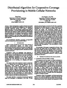
Figure 1. 3G and 4G system design targets.
issue and solutions can be of an evolutionary nature for backward compatibility consideration, or they can be rather revolutionary. In this article we focus on the former. The article is organized as follows. In the following section, the LTE coverage issue is described. Next we illustrate the process of limiting link identification. Then we discuss several candidate solutions to LTE coverage enhancements. The conclusions are provided in the final section.
LTE COVERAGE ISSUES FUNDAMENTAL LIMITATIONS OFDM is a key feature of mainstream 4G wireless standards including LTE/LTE-A. The coherence nature of multiple carriers in OFDM leads to a higher peak to average power ratio (PAPR) compared to the modulation schemes in 2G and 3G. Because of this, the linearity requirement for power amplifiers is more stringent, which results in poor efficiency of power amplifiers. This poses serious issues for coverage, especially in the uplink since the transmission power of mobile terminals (UEs) is quite limited. In LTE uplink, single-carrier frequency division multiple access (SC-FDMA) is adopted, with the purpose to reduce the PAPR. SC-FDMA requires that a UE be allocated with a continuous but mutually non-orthogonal block of resources that forms a “single carrier.” Even with SC-FDMA, LTE uplink is still an orthogonal frequency division multiple access (OFDMA) system. It does not have soft handover as code division multiple access (CDMA) in 3G which can improve the SINR at cell edges. The inter-cell interference statistics of OFDMA systems cannot be accurately modeled as Gaussian as in the case of CDMA systems, making it harder to maintain robust links at cell edges.
154
To reduce the air-interface latency, a short subframe structure is adopted for LTE/LTE-A systems. The 1 ms duration of TTI, or one subframe, is shorter than 2ms-TTI in HSPA and 20ms-TTI in Release 99 UMTS. Since they all carry the similar payload, transmit energy is more concentrated in time for LTE/LTE-A, which inherently burdens the link budget. While the shorter TTI would allow more accurate link adaptation and reduce the latency, which can improve the transmission efficiency to some extent, in general higher instantaneous transmission power is expected for LTE than HSPA or CDMA. As seen in Fig. 1, 4G system design emphasizes spectral efficiency improvement where the operating SNR is noticeably higher than that of 3G systems. The green squares in Fig. 1 correspond to practically achievable spectral efficiencies of various physical channels in 3G and 4G. The solid green curve is the fitting of those squares. Higher operating SNR will inevitably cause higher power consumption. The UE battery lifetime for 4G will become more critical compared to that for 3G. In contrast, power efficiency was a major design consideration in 3G, which generally benefits the coverage. So even operating in the same frequency, the receiver sensitivity of EV-DO or UMTS would be several dBs better than that of LTE, for both VoIP and other low data rate services.
DEPLOYMENT SPECIFIC As a truly global standard, LTE/LTE-A supports diverse operations that cover different spectrum bands. However, in many cases LTE/LTE-A is likely to be deployed at higher frequencies than those in existing 2G and 3G systems, even though in the United States of America LTE was firstly deployed at near 700MHz, which was originally for TV broadcasting. In higher bands, the channel would experience severe path loss and building penetration loss. Less scatters are seen at high frequencies, indicating the lack of diversity, which can otherwise be used to mitigate the severe path loss. With the higher bands allocation for LTE/LTE-A compared to 3G, operators face challenges in ensuring proper coverage in practical deployments. Wireless operators may pursue different paths for migration from 3G to LTE, depending on technologies used in 3G, spectrum allocation, and other factors. Smooth migration is preferred by many operators, for example, to reuse the cell sites of 3G systems and to avoid excessive initial expenditure in adding the new sites. For operators who had chosen CDMA 1x and EV-DO for their 3G networks, the coverage issues may be more challenging and there may be more cell planning work to be done as the systems evolve to LTE. Table 1 shows the numbers of base stations (BSs in Ev-DO or eNBs in LTE) needed in China Telecom’s network in the Shanghai metropolitan area. Link budget analysis is used to predict the cell size. It is observed in the case of EV-DO that the actual cell radius is smaller than estimated. This may be explained by the non-hexagonal cell shape and less uniform site-to-site distance in real deployment. A similar situation is expected in LTE. The difference in the estimated cell radius between EV-DO and LTE is due to:
IEEE Communications Magazine • October 2014
YUAN_LAYOUT_Layout 9/25/14 12:56 PM Page 155
• Lower SNR required for EV-DO receivers in order to achieve the similar rate. • About 16 dB path loss shortfall of an LTE system that operates at 2.535 GHz, rather than 835 MHz for EVDO. The much increased path loss for the higher band would make the cell size much reduced and the number of eNBs significantly increased.
LIMITING LINK IDENTIFICATION Uplink LTE/LTE-A physical channels have different formats and thus require different SNRs for correct decoding. Coverage is usually limited by one or two channels. So the first step of the coverage enhancements study is to identify limiting links.
EVALUATION METHODOLOGY For practical systems, coverage can be measured in various ways. In standards development bodies, three methods are commonly used to quantify the coverage. Maximum Coupling Loss (MCL) — The coupling loss is basically the total long-term channel loss over the link between the transmit antenna ports and the receiving antenna ports. MCL is the upper limit of the coupling loss, which defines the coverage of a physical channel. MCL depends only on the transmit power and the receiver sensitivity. The receiver sensitivity is determined by the required SINR, thermal noise density, receiver noise figure, and the occupied bandwidth. Link Budget — Link budget can be seen as a refined version of maximum coupling loss. The exact formula for link budget calculation may be channel/service dependent. Nevertheless, a typical link budget table would include a few extra entries, for example: hybrid automatic repeat request (HARQ) gain, which captures the effective rate due to early termination; system loading, which reflects the inter-cell interference level; and edge coverage reliability, which measures the confidence of coverage. These additional parameters help to more accurately capture the real deployment. Similar to MCL, link budget analysis relies primarily on the required SINR to calculate the coverage, and the required SINR is based on the link level simulations. System Level Simulations — The cell edge throughput, usually counting the 5 percentile UEs in the systems, is highly related to the coverage. Edge throughput is typically used for traffic channels, although control channels such as physical downlink control channel (PDCCH) and physical uplink control channel (PUCCH) may also be studied using this metric. The obtained cell edge rate can be affected by many factors, much more than those for MCL and link budget calculations. Among them are the scheduler implementations, inter-cell interference coordination, which can reduce the interference seen by cell edge UEs, multiuser diversity, and so on. In a 3GPP LTE enhancements study [4],
IEEE Communications Magazine • October 2014
EV-DO
LTE
Predict r (km)
Actual r (km)
Predict # BSs
Actual # BSs
Predict r (km)
Predict # eNBs
Dense urban
0.46
0.38
287
425
0.23
1096
Urban
0.83
0.51
194
503
0.40
846
Suburb
2.25
1.21
144
495
0.94
818
Table 1. Number of eNBs predicted and actually deployed in Shanghai metropolitan area.
MCL is chosen as the evaluation methodology for its simplicity. As the uplink is usually more coverage limited than the downlink, in this article we focus on uplink channels. Interested readers can refer to [4] for more comprehensive simulations for an LTE coverage enhancement study. Table 2 summarizes the simulation parameters for the bottleneck channel identification Major uplink physical channels are simulated. Note that for physical uplink shared channel (PUSCH, essentially the uplink traffic channel) simulations, the number of UL physical resource blocks (PRB), the modulation and coding scheme (MCS), and the maximum number of HARQ transmissions are not specified in Table 2. It is up to each company to choose appropriate settings to get the best performance for each service/rate. The initial block error rate (BLER) is counted after the first HARQ transmission, and the residual BLER is counted after the maximum number of HARQ transmissions is reached. For PUSCH Message 3, Message 4, and UL VoIP, the inter-subframe frequency hopping is enabled. For VoIP, TTI bundling of Release 8 is used. PUCCH format 2 is assumed to carry four bits.
COVERAGE COMPARISONS The MCL of LTE uplink channels are compared in Table 3, which is originally from [4]. It is observed that the coverage of PUSCH medium data rate 384 kb/s is much worse than other channels. VoIP traffic channel is also a limiting link, even with Release 8 TTI bundling. Random access channel (RACH) and its subsequent PUSCH message 3 with transport block size (TBS) of 144 bits are the potential bottleneck. Note that for RACH, a relaxed performance target, for example 10 percent miss-detection probability (Pmiss), can be used if the latency requirement for the random access procedure is not critical. The relaxed target can improve the MCL of RACH by 4~6 dB. Based on the MCL evaluations, the PUSCH medium data rate of 384 kb/s and UL VoIP are identified as the limiting links that need coverage enhancements.
POTENTIAL SCHEMES BRIEF DESCRIPTION OF SOLUTIONS From the above discussions, it is seen that the coverage issue of LTE/LTE-A stems from the different design principles of 3G and 4G, as well
155
YUAN_LAYOUT_Layout 9/25/14 12:57 PM Page 156
Parameters
Values
Channel
MCL (dB)
Services and bit rates
Service 1: VoIP (UL 12.2 kb/s) Service 2: Web browsing (UL 384 kb/s)
RACH format 2
141.8
PUCCH format 1
146.5
System bandwidth
10 MHz PUCCH format 1a
147.2
UE Tx power
23 dBm PUCCH format 2
146
Num. of eNB Rx antennas
2 Message 3 TBS 56
146.7
Antenna configuration UE
1 Tx Message 3 TBS 144
143.3
eNB receiver noise figure
5 dB VoIP AMR 12.2 kb/s
141.7
Radio channel
Enhanced Pedestrian A, 3 km/h Medium data rate 384 kb/s
132.4
Thermal noise PSD
–174 dBm/Hz
Max number of HARQ transmissions for PUSCH
4
Performance target
• 1 percent Pmiss and 0.1 percent Pfa for RACH format 2 • 1 percent Pmiss and 1 percent Pfa for PUCCH format 1/1a • 1 percent BLER for PUCCH format 2 • 10 percent residual BLER for PUSCH Message 3 and 4 • 2 percent residual BLER for VoIP • 10 percent initial BLER for PUSCH media data rate 384 kb/s
Table 2. LTE uplink simulation parameters for limiting link identification.
as the deployment-specific factors. For such a generic problem, the ultimate solution requires an overhaul of the entire LTE specifications, which is certainly not desirable. Instead, more realistic goals can be set, for example, 1 dB improvement, so that we can focus on a small number of enhancement features that have less specification impacts. Coverage enhancement solutions can be categorized as: • Air interface specification impacting. • Implementation based without specification changes, for example, no work needed in 3GPP RAN1 working group. In the former category, the following schemes have been proposed. TTI Bundling Enhancements — More energy can be accumulated by increasing the transmission time of a packet. In Release 8 LTE, TTI bundling is used for uplink. It can support up to 4-TTI bundling and limited to 3 PRBs. For coverage enhancements, TTI bundling with more than three PRBs per subframe can be considered for the PUSCH medium data rate to make the channel coding more efficient. In addition, for uplink VoIP, more flexible HARQ timing and bundling size can be studied. Using Spreading Codes — Spreading code is another way to achieve the lower rate and thus improve the coverage. Compared to the straightforward repetition, spreading can strengthen the
156
Table 3. MCLs of LTE uplink channels [4].
link robustness against interference, similar to CDMA systems. For LTE uplink, spreading is already supported in PUCCH format 3, and it forms a good base for CDMA channelization for UL VoIP for coverage enhancement. Note that this scheme requires resource coordination among neighboring cells. Frequency Hopping Enhancements — Frequency hopping can provide frequency diversity, which is crucial to coverage. On the other hand, frequency hopping makes it difficult to jointly estimate the channel over multiple subframes. Such joint estimation can improve the accuracy if the channel varies slowly. LTE Release 8 offers very limited choices of frequency hopping. There may still be room for further enhancements to provide a better trade-off between the frequency diversity and channel estimation accuracy [5]. Fig. 2 shows two examples, corresponding to inter-subframe hopping only and both inter/intra subframe hopping. With these new patterns, both the gains of joint decoding and time-frequency diversity can be obtained. Implementation-based solutions are listed below. Although none of them requires standardization in RAN1, 3GPP needs to define the minimum performance requirements for some schemes. 1.8 Rx Antennas at eNB — Extending the number of receive antennas to eight is an efficient way to improve LTE UL coverage. It is equivalent to increasing the “aperture” of the receiver, thus improving the sensitivity. LTE already supports eight Tx antennas on the downlink, and therefore it is straightforward to support eight Rx antennas on the uplink One typical configuration is the cross-polarization antennas where in each polarization direction, four closely-spaced antennas form a uniform linear array (ULA). In 3GPP, a work item [6] was created to specify the minimum performance requirement for an eNB receiver of eight Rx antennas. Advanced Receiver — Compared to the baseline receiver, advanced receivers such as an interference rejection/cancellation (IRC) receiv-
IEEE Communications Magazine • October 2014
YUAN_LAYOUT_Layout 9/25/14 12:57 PM Page 157
Slot
Hopping bandwidth
er or a non-linear interference cancellation receiver could mitigate both intra-cell and the inter-cell interference. In a RAN4 study, the IRC receiver has shown better performance than the baseline receiver at cell edge. The non-linear interference cancellation receiver could provide significant gain over linear receivers by suppressing strong interference from common reference signal (CRS), primary synchronization signal (PSS), secondary synchronization signal (SSS), and primary broadcast channel (PBCH).
Hopping period (a)
Power Boosting of Demodulation Reference Signal — As the operating SNR is pushed lower to improve the coverage, the receiving quality of the reference signal becomes a serious issue. Boosting the power of demodulation reference signal (DMRS) would improve the robustness of the channel estimation in low SNR regions. Since QPSK is most likely to be used in coverage-limiting scenarios, increasing the power of DMRS does not require specification change. On the uplink it is more or less a UE implementation issue. However, this solution may bring some challenges to UE vendors. For example, in a subframe of LTE uplink, the DMRS is time multiplexed with the data symbols (PUSCH). Certain transition time is needed to ramp up and ramp down the transmit power. The roundoff waveform of the DMRS would reduce the original gain of DMRS power boosting. Also, the un-even power level within a subframe tends to lower the efficiency of the amplifiers. In the following sections we will focus on specification-impacting solutions, in particular the TTI bundling enhancements that quickly became the popular choice among interested companies. For performance evaluations of other candidate schemes, readers are referred to [4] for more details.
Hopping bandwidth
Slot
Hopping period (b)
Figure 2. Examples of frequency hopping enhancements. a) Inter-subframe hopping; enhancements; b) Inter- and intra subframe hopping enhancements.
1472 bits from PDCP
MAC header
24
RLC header
RLC/MAC
16
1472 bits from PDCP
Subframe
Packet for 4 TTIs
CRC
24
ENHANCED SUBFRAME BUNDLING SCHEMES TTI bundling in LTE Release 8 is mainly for VoIP, and the total transmit energy of a VoIP packet is evenly distributed over multiple subframes. TTI bundling can be extended to PUSCH medium data rate, with the following motivations: • To reduce the overhead of upper layer signaling. • To improve the efficiency of the channel coding. • To have more time diversity as the transmission of an aggregated packet can span over a longer time duration. Unlike in VoIP, a packet size of PUSCH 384 kb/s can easily go beyond 400 bits. Hence the restriction of three physical resource blocks (PRBs) in Release 8 TTI bundling can be lifted so that the TTI bundling for medium data rate PUSCH would be done more efficiently. Fig. 3 is an example of 384 kb/s transmission where four smaller packets are bundled into a larger packet of 1504 bits. Those four subframes that carry the aggregate packet may not be adjacent to each other in time, as seen in Fig. 3. In the case of no TTI bundling, at the radio link control (RLC) layer, the transmission rate of 384 kb/s corresponds to one packet convergence protocol (PDCP) packet data unit (PDU)
IEEE Communications Magazine • October 2014
#0
#1
#2
#3
#4
#5
#6
#7
Figure 3. An example of bundled packets for 384 kb/s transmission at RLC layer.
of 368 bits plus a 2-byte RLC header at each subframe. After adding a 3-byte medium access control (MAC) header and a 24-bit cyclic redundancy check (CRC), each physical layer (PHY) PDU has 432 bits. Hence, four such PHY PDUs contain 1728 bits in total. With TTI bundling, four PDCP PDUs are concatenated into a 1472-bit PDU, to be sent in four subframes. With a 5-byte RLC/MAC header and a 24-bit CRC, the size of the single PHY PDU becomes 1536 bits. In this case, the saving of upper layer signaling overhead is 192 bits, roughly 0.5 dB. The gain from larger Turbo interleaver size, for example, 432 to 1536 bits, is about 0.3~0.6 dB (Table 4) for additive white Gaussian noise (AWGN) channel and enhanced pedestrian A (ePA) channel. So combining the gain of overhead reduction and the gain of longer interleaver, the TTI bundling for medium data rate of 384 kb/s is roughly 1 dB.
157
YUAN_LAYOUT_Layout 9/25/14 12:57 PM Page 158
During a talk spurt, a VoIP packet arrives at the physical layer every 20 ms. In theory, a maximum of 20 subframes can be used for the transmission of each VoIP packet. However, if the delay bound is imposed, the actual number of subframes used for a VoIP packet can be less than 20. For Release 8 TTI bundling, maximum usage of 12 or 16 subframes can be achieved for 50 ms or 52 ms delay bound, respectively. RLC segmentation is an alternative scheme to improve the subframe utilization. However, due to the very high overhead, the overall perforOverhead reduction
Turbo interleaver gain
Total gain in MCL
~0.5
0.3~0.6 dB
0.8~1.1 dB
Table 4. MCL gain from TTI bundling enhancement for PUSCH 384 kb/s.
0 ms
20 ms
40 ms
60 ms
(a) 0 ms
20 ms
40 ms
60 ms
(b) 0 ms
20 ms
40 ms
60 ms
(c) 0 ms
20 ms
40 ms
60 ms
(d) 0 ms
20 ms
40 ms
60 ms
(e) 0 ms
20 ms
40 ms
60 ms
(f) 0 ms
20 ms
40 ms
60 ms
(g)
Figure 4. TTI bundling enhancement schemes for UL VoIP. a) 8-TTI bundling, RTT = 16 ms, MaxTx = 2; b) 4-TTI bundling, RTT = 8 ms, MaxTx = 5; c) 4-TTI bundling, RTT = 12 ms, MaxTx = 5; d) 20-TTI bundling, MaxTx = 1; e) 10-TTI bundling, RTT = 30 ms, MaxTx = 2; f) Flexible bundling sizes, RTT = 16 ms, MaxTx = 4; g) 5-TTI bundling, RTT = 15 ms, MaxTx = 4.
mance of RLC segmentation is worse than TTI bundling. Thus RLC segmentation was not further studied in [4]. Figure 3 shows several schemes of TTI bundling enhancements for UL VoIP. Color code is used to differentiate transmissions of different VoIP packets, and the same color blocks are the transmission or HARQ retransmission for a VoIP packet. LTE uplink HARQ is synchronous, for example, the time gap between HARQ (re)transmissions is fixed, exhibiting a period pattern. Fig. 4a illustrates a straightforward extension of 4-TTI bundling in Release 8 to 8-TTI bundling. The round trip time (RTT) is still kept 16 ms. In this scheme, up to two HARQ transmissions can be supported, that is, the maximum number of transmissions (MaxTx) = 2. Otherwise, the third HARQ transmission would collide with the transmissions of other VoIP packets (although not explicitly shown in this figure). The number of subframes for a UL VoIP packet would be up to 16 in this scheme. In Figs. 4b and 4c, the TTI bundling size is 4 TTI, similar to that of Rel-8. The difference is that the round trip time is reduced, which requires faster signal processing at the eNB receiver to decode the VoIP packet in time. Both schemes can fully utilize the subframe resource, for example, 20 subframes. The scheme in Fig. 4d can reuse the frame structure of circuit switch voice, that is, 20-TTI aggregation, without HARQ retransmissions. Note that the subframes can be interleaved, as shown in the lower plot of Fig. 4d. This can improve the time diversity. The scheme in Fig. 4e bundles 10 TTIs, and allows two HARQ transmissions. The scheme in Fig. 4f extends Release 8 TTI bundling by increasing one of the bundles to eight TTIs, for example, transmitting eight TTIs in the first HARQ transmission. Bundling size of five TTIs is shown in Fig. 4g. Simulations show that the gain from the above TTI bundling ranges from 0.6 dB to 2 dB. Among them, schemes (c)/(f)/(g) perform the best. In light of the low complexity and compatibility with Release 8 TTI bundling, scheme (c) was adopted for VoIP coverage enhancement in Release 12.
CONCLUSIONS In this article the LTE coverage issue was described, not only from the aspect of fundamental technologies of 3G and 4G, but also in the context of deployment scenarios such as carrier frequencies. Evaluation methodology was then discussed. From the maximum coupling loss analysis, PUSCH medium data rate 384 kb/s and uplink VoIP were identified as the bottleneck links for LTE. Both specification-impacting schemes and implementation-based solutions were presented. Among the specification-impacting solutions, TTI bundling enhancements show promise in improving the coverage of PUSCH medium data rate and UL VoIP.
REFERENCES [1] 3GPP TR 36.814, “Evolved Universal Terrestrial Radio Access (E-UTRA); Further Advancements for E-UTRA Physical Layer Aspects.” [2] 3GPP, R1-080339, “On VoIP Uplink Coverage for LTE,” Ericsson, Jan. 2008.
IEEE Communications Magazine • October 2014
YUAN_LAYOUT_Layout 9/25/14 12:57 PM Page 159
[3] 3GPP TR 36.888, “Technical Specification Group Radio Access Network; Study on Provision of Low-Cost MTC UEs Based on LTE.” [4] 3GPP TR 36.824, “Evolved Universal Terrestrial Radio Access (E-UTRA); LTE Coverage Enhancements.” [5] 3GPP, R1-122130, “TTI Bundling Enhancements Details for PUSCH Medium Data Rate,” ZTE, May 2012. [6] 3GPP, RP-121709, “Proposed WI on Performance Requirements of 8 Rx Antennas for LTE UL,” China Telecom, Barcelona, Dec. 2012.
BIOGRAPHIES YIFEI YUAN (
[email protected]) received Bachelor and Master degrees from Tsinghua University of China, and a Ph.D. from Carnegie Mellon University, USA. He was with Alcatel-Lucent from 2000 to 2008, working on 3G/4G key technologies. Since 2008 he has been with ZTE, responsible for standards research on LTE-Advanced physical layer, and recently on 5G technologies. His research interests include MIMO, iterative codes, and resource scheduling. He was admitted to the Thousand Talent Plan Program of China in 2010. He has extensive publications, including two books on LTE-A. ZHISONG ZUO (
[email protected]) received his degree of Master in computer science from Portland State University, Oregon. He joined ZTE Corporation in 2003 and currently serves as the chief delegate in 3GPP RAN1. He has been involved in the research and standardization of the LTE physical layer protocol since 2005. His research interests include OFDM system, small cells, control channel, and channel coding. Y ANFENG G UAN received a B.S. degree from North China University of Water Conservancy & Electric Power in 2000, an M.S. degree from HeHai University in 2003, and a Ph.D. from Southeast University in 2007. From 2007 to 2013 he was a senior engineer at the Wireless Research Institute at ZTE, and worked in wireless communication standards and research. His research interests are in the broad area of communication, particularly resource management and signal processing for wireless communication.
IEEE Communications Magazine • October 2014
XIANMING CHEN (
[email protected]) received the Master degree in communication and information system from Harbin Engineering University of China in 2009. He has been at ZTE as a senior engineer since 2009, engaged in research on wireless communication technologies and standards. His main areas of research include LTE coverage enhancement technologies and 5G key technologies, for example, massive MIMO. W EI L UO (
[email protected]) received the Master degree in communication engineering from Huazhong University of Science and Technology of China in 2008. She has been in ZTE since 2008, where she works on the Wireless Advance Research team. Her main areas of research include wireless system design and LTE radio access network technologies, for example, CoMP interference coordination and small cell enhancement. QI BI (
[email protected]) is the President of the Technology Innovation Center and the CTO of Beijing Research Institute of China Telecom. He received his M.S. from Shanghai Jiao Tong University and Ph.D. from Pennsylvania State University. Prior to joining China Telecom in 2010 he worked at Bell Labs for 20 years and became a Bell Labs Fellow in 2002. He is an IEEE fellow. He has published extensively and holds 42 US patents and 66 European patents. P ENG C HEN (
[email protected]) received his Ph.D. degree in electronic engineering in 2006 from Beijing University of Posts and Telecommunications. He has been with China Telecom Innovation Center since 2010, working on LTE-A standardization in 3GPP RAN and cutting-edge technology for IMT-2020. He is the rapporteur for the 3GPP LTE Rel-11 coverage enhancement study item. X IAOMING S HE (
[email protected]) received his Ph.D. degree in electronic engineering in 2004 from Tsinghua University. He has been with China Telecom Innovation Center since 2012, working on LTE-A standardization in 3GPP RAN and cutting-edge technology for IMT-2020. He is currently the rapporteur for the 3GPP LTE Rel-12 coverage enhancement work item.
159