Nov 21, 2014 ... (TFTP) server, and receive and transmit throughput tests. ... AP SoC device web
server applications and shows the high-speed performance of.
Application Note: Embedded Processing
LightWeight IP Application Examples XAPP1026 (v5.1) November 21, 2014
Author: Anirudha Sarangi, Stephen MacMahon, and Upender Cherukupaly
Summary Lightweight IP (lwIP) is an open source TCP/IP networking stack for embedded systems. The Xilinx® Software Development Kit (SDK) provides lwIP software customized to run on various Xilinx embedded systems that can be MicroBlaze™ or PowerPC® processor based. The Xilinx SDK provided lwIP software can also be run on ARM®-based Xilinx Zynq®-7000 All Programmable (AP) SoC. The information in this application note applies to MicroBlaze processors and ARM-based Zynq-7000 AP SoC systems. This document describes how to use the lwIP library to add networking capability to an embedded system. In particular, lwIP is utilized to develop these applications: echo server, web server, Trivial File Transfer Protocol (TFTP) server, and receive and transmit throughput tests. You can download the Reference Design Files for this application note from the Xilinx website. For detailed information about the design files, see Reference Design.
Hardware and Software Requirements The hardware and software requirements are: •
One of the Xilinx Artix®-7 AC701 or Kintex®-7 KC705 boards for MicroBlaze processor-based systems and a ZC-702 board for Zynq-7000 AP SoC-based systems
•
Xilinx JTAG for MicroBlaze processor-based and Zynq-7000 AP SoC-based systems
•
USB cable for RS232 UART communication on the board
•
An Ethernet cable connecting the board to a Windows or Linux host
•
Xilinx Platform USB cable for MicroBlaze processor-based and Xilinx JTAG for Zynq-7000 AP SoC-based systems
•
Serial Communications Utility Program, such as HyperTerminal or Teraterm
•
Xilinx Vivado 2014.3 for creating hardware modifications for AC701, KC705, and ZC-702
•
Xilinx SDK 2014.3 for running or creating hardware modifications to the software for AC701, KC705, and ZC-702
XAPP1026 (v5.1) November 21, 2014
www.xilinx.com
Send Feedback
1
Introduction
Introduction lwIP is an open source networking stack designed for embedded systems. It is provided under a Berkeley Software Distribution (BSD) style license. The objective of this application note is to describe how to use lwIP shipped along with the Xilinx SDK to add networking capability to an embedded system. In general, this application note describes how applications such as an echo server or a web server can be written using lwIP. The Xilinx SDK 2014.3 does not have support for lwIP 1.4.1. However, this document gives details about how to add lwIP 1.4.1 to Zynq-7000 AP SoC, Artix-701, and Kintex-705 devices. The lwIP 1.4.0 library released as part of Xilinx Platform Studio 14.3 and used in the reference designs for ML605 and SP605. This version of the document does not cover ISE® Design Suite and lwIP 1.4.0 reference design details but a brief summary and information on design files are provided in Appendix A: ML605 and SP605 Design Information, page 26.
Reference System Specifics The reference design for this application note is structured as follows: •
AC701_AxiEth_32kb_Cache,AC701_AxiEth_64kb_Cache, KC705_AxiEth_32kb_Cache, KC705_AxiEth_64kb_Cache, KC705_AxiEthernetlite_64kb_Cache,and ZC702_GigE folders correspond to the various supported boards and hardware designs for Artix-7, Kintex-7, and Zynq-7000 AP SoC.
•
In each folder, the HW subdirectory contains the Xilinx Vivado 2014.3 for Artix-7, Kintex-7, and Zynq-7000 AP SoC. The SW subdirectory contains the application software and software platforms that need to be imported into SDK.
•
The ready_for_download folder contains these relevant files for getting started with the applications: °
download.bit: Bitstream to be downloaded to the board. Applicable only for MicroBlaze processor-based systems.
°
system_bd.bmm: For downloading the bitstream. Applicable only for MicroBlaze processor-based systems.
°
image.mfs: Memory File System (MFS) used for TFTP and web server applications.
°
image_BIG.mfs: Provided only in the ready_to_download folder for the ZC702_GigE hardware system. This is a large MFS file that can be used for Zynq-7000 AP SoC device web server applications and shows the high-speed performance of Zynq-7000 AP SoC devices.
°
raw_apps.elf: Application ELF image to be downloaded to test the RAW API.
°
socket_apps.elf: Application ELF image to be downloaded to test the socket API.
XAPP1026 (v5.1) November 21, 2014
www.xilinx.com
Send Feedback
2
Reference System Specifics °
fsbl.elf: First stage boot loader applicable only for Zynq-7000 AP SoC systems to initialize the MIOs/Clocks.
•
The memfs folder contains the contents of the MFS image.
•
The image itself is also present as the image.mfs file in the respective ready_for_download folders. For Zynq-7000 AP SoC devices, two MFS files are provided. The standard image.mfs (common for all boards) is present along with a large MFS file (image_BIG.mfs) that contains huge web page contents. However, memfs contents for this image_BIG.mfs is not provided.
•
ZC702_GigE has a repository folder which contains FreeRTOS BSP, based on the latest tool version release. It also has lwIP 1.4.1 TCP/IP stack.
•
For MicroBlaze processor-based systems, it has a repository folder for lwIP 1.4.1 TCP/IP stack for Artix-7 and Kintex-7 devices.
Hardware Systems For Artix-7, Kintex-7, and Zynq-7000 AP SoC devices, the hardware systems for the available boards were built using Vivado 2014.3. For more information on hardware requirements for lwIP, see the lwIP documentation available as part of the SDK installation. Table 1 provides a summary of the hardware designs for the available boards. Table 1:
Hardware Design Details
Hardware Design Name
Processor
Processor Frequency
Ethernet Controller
DMA
AC701_AxiEth_32kb_Cache
MicroBlaze
100 MHz
axi_ethernet
axi_dma
AC701_AxiEth_64kb_Cache
MicroBlaze
100 MHz
axi_ethernet
axi_dma
KC705_AxiEth_32kb_Cache
MicroBlaze
150 MHz
axi_ethernet
axi_dma
KC705_AxiEth_64kb_Cache
MicroBlaze
150 MHz
axi_ethernet
axi_dma
KC705_AxiEthernetlite_64kb_Cache
MicroBlaze
150 MHz
axi_ethernetlite
None
ZC702_GigE
ARM Cortex-A9
666.667 MHz
GigE
Built-In
Notes: 1. All axi_ethernet-based systems are built with full checksum (both TCP and IP checksums) offload feature. 2. The axi_ethernetlite-based systems are built with ping-pong buffers (one more buffer for both TX and RX paths to improve performance). 3. The GigE-based systems (Zynq-7000 AP SoC devices) have a built-in TCP/IP checksum offload support.
XAPP1026 (v5.1) November 21, 2014
www.xilinx.com
Send Feedback
3
Software Applications
Software Applications The reference design includes these software applications: •
Echo server
•
Web server
•
TFTP server
•
TCP RX throughput test
•
TCP TX throughput test
All of these applications are available in both RAW and socket modes.
Echo Server The echo server is a simple program that echoes input that is sent to the program through the network. This application provides a good starting point for investigating how to write lwIP applications. The socket mode echo server is structured as follows: 1. A main thread listens continually on a specified echo server port. 2. For each connection request, it spawns a separate echo service thread. 3. It then continues listening on the echo port. while (1) { new_sd = lwip_accept(sock, (struct sockaddr *)&remote, &size); sys_thread_new(process_echo_request, (void*)new_sd, DEFAULT_THREAD_PRIO); }
The echo service thread receives a new socket descriptor as its input on which it can read received data. This thread does the actual echoing of the input to the originator. while (1) { /* read a max of RECV_BUF_SIZE bytes from socket */ n = lwip_read(sd, recv_buf, RECV_BUF_SIZE)); /* handle request */ nwrote = lwip_write(sd, recv_buf, n)); }
Note: These code snippets are not complete and are intended to show the major structure of the code
only.
The socket mode provides a simple API that blocks on socket reads and writes until they are complete. However, the socket API requires many pieces to achieve this, including primarily a simple multi-threaded kernel (xilkernel for MicroBlaze processor-based systems and FreeRTOS for Zynq-7000 AP SoC systems). Because this API contains significant overhead for all operations, it is slow.
XAPP1026 (v5.1) November 21, 2014
www.xilinx.com
Send Feedback
4
Software Applications The RAW API provides a callback style interface to the application. For applications using the RAW API register callback, these functions are called on significant events such as accept, read, or write. A RAW API-based echo server is single-threaded and all the work is done in the callback functions. The main application loop is structured as follows: while (1) { if (TcpFastTmrFlag) { tcp_fasttmr(); TcpFastTmrFlag = 0; } if (TcpSlowTmrFlag) { tcp_slowtmr(); TcpSlowTmrFlag = 0; } xemacif_input(netif); transfer_data(); }
The TcpFastTmrFlag and TcpSlowTmrFlag are required for TCP TX handling and are set in the Timer handler for every 250 ms and 500 ms, respectively. The function of the application loop is to receive packets constantly (xemacif_input), then pass them on to lwIP. Before entering this loop, the echo server sets up certain callbacks: /* create new TCP PCB structure */ pcb = tcp_new(); /* bind to specified @port */ err = tcp_bind(pcb, IP_ADDR_ANY, port); /* we do not need any arguments to callback functions */ tcp_arg(pcb, NULL); /* listen for connections */ pcb = tcp_listen(pcb); /* specify callback to use for incoming connections */ tcp_accept(pcb, accept_callback);
This sequence of calls creates a TCP connection and sets up a callback on a connection being accepted. When a connection request is accepted, the function accept_callback is called asynchronously. Because an echo server needs to respond only when data is received, the accept callback function sets up the receive callback by performing: /* set the receive callback for this connection */ tcp_recv(newpcb, recv_callback);
When a packet is received, the function recv_callback is called. The function then echoes the data it receives back to the sender: /* indicate that the packet has been received */ tcp_recved(tpcb, p->len); /* echo back the payload */ err = tcp_write(tpcb, p->payload, p->len, 1);
XAPP1026 (v5.1) November 21, 2014
www.xilinx.com
Send Feedback
5
Software Applications Although the RAW API is more complex than the socket API, it provides much higher throughput because it does not have a high overhead.
Web Server A simple web server implementation is provided as a reference for TCP-based application. The web server implements only a subset of the HTTP 1.1 protocol. Such a web server can be used to control or monitor an embedded platform through a browser. The web server demonstrates these features: •
Accessing files residing on a Memory File System through HTTP GET commands
•
Controlling the LED lights on the development board using the HTTP POST command
•
Obtaining status of DIP switches on the development board using the HTTP POST command
The Xilinx Memory File System (xilmfs) is used to store a set of files in the memory of the development board. These files can then be accessed through an HTTP GET command by pointing a web browser to the IP address of the development board and requesting specific files. Controlling or monitoring the status of components in the board is done by issuing POST commands to a set of URLs that map to devices. When the web server receives a POST command to a URL that it recognizes, it calls a specific function to do the work that has been requested. The output of this function is sent back to the web browser in Javascript Object Notation (JSON) format. The web browser then interprets the data received and updates its display. The overall structure of the web server is similar to the echo server—there is one main thread which listens on the HTTP port (80) for incoming connections. For every incoming connection, a new thread is spawned that processes the request on that connection. The HTTP thread first reads the request, identifies if it is a GET or a POST operation, then performs the appropriate operation. For a GET request, the thread looks for a specific file in the memory file system. If this file is present, it is returned to the web browser initiating the request. If it is not available, a HTTP 404 error code is sent back to the browser. In socket mode, the HTTP thread is structured as follows: /* read in the request */ if ((read_len = read(sd, recv_buf, RECV_BUF_SIZE)) < 0) return; /* respond to request */ generate_response(sd, recv_buf, read_len);
Pseudo code for the generate response function is as follows: /* generate and write out an appropriate response for the http request */ int generate_response(int sd, char *http_req, int http_req_len) { enum http_req_type request_type =
XAPP1026 (v5.1) November 21, 2014
www.xilinx.com
Send Feedback
6
Software Applications decode_http_request(http_req, http_req_len); switch(request_type) { case HTTP_GET: return do_http_get(sd, http_req, http_req_len); case HTTP_POST: return do_http_post(sd, http_req, http_req_len); default: return do_404(sd, http_req, http_req_len); } }
The RAW mode web server primarily uses callback functions to perform its tasks. When a new connection is accepted, the accept callback function sets up the send and receive callback functions. These are called when sent data has been acknowledged or when data is received. err_t accept_callback(void *arg, struct tcp_pcb *newpcb, err_t err) { /* keep a count of connection # */ tcp_arg(newpcb, (void*)palloc_arg()); tcp_recv(newpcb, recv_callback); tcp_sent(newpcb, sent_callback); return ERR_OK; }
When a web page is requested, the recv_callback function is called. This function then performs tasks similar to the socket mode function—decoding the request and sending the appropriate response. /* acknowledge that we have read the payload */ tcp_recved(tpcb, p->len); /* read and decipher the request */ /* this function takes care of generating a request, sending it, * and closing the connection if all data has been sent. If * not, then it sets up the appropriate arguments to the sent * callback handler. */ generate_response(tpcb, p->payload, p->len); /* free received packet */ pbuf_free(p);
The data transmission is complex. In the socket mode, the application sends data using the lwip_write API. This function blocks if the TCP send buffers are full. However, in RAW mode the application determines how much data can be sent and sends only that much data. Further data can be sent only when space is available in the send buffers. Space becomes available when sent data is acknowledged by the receiver (the client computer). When this occurs, lwIP calls the sent_callback function, indicating that data was sent and there is now space in the send buffers for more data. The sent_callback is structured as follows: err_t sent_callback(void *arg, struct tcp_pcb *tpcb, u16_t len) { int BUFSIZE = 1024, sndbuf, n; char buf[BUFSIZE]; http_arg *a = (http_arg*)arg;
XAPP1026 (v5.1) November 21, 2014
www.xilinx.com
Send Feedback
7
Software Applications
/* if connection is closed, or there is no data to send */ if (tpcb->state > ESTABLISHED) { return ERR_OK; } /* read more data out of the file and send it */ sndbuf = tcp_sndbuf(tpcb); if (sndbuf < BUFSIZE) return ERR_OK; n = mfs_file_read(a->fd, buf, BUFSIZE); tcp_write(tpcb, buf, n, 1); /* update data structure indicating how many bytes * are left to be sent */ a->fsize -= n; if (a->fsize == 0) { mfs_file_close(a->fd); a->fd = 0; } return ERR_OK; }
Both the sent and the receive callbacks are called with an argument that can be set using tcp_arg. For the web server, this argument points to a data structure that maintains a count of how many bytes remain to be sent and what is the file descriptor that can be used to read this file.
TFTP Server TFTP is a UDP-based protocol for sending and receiving files. Because UDP does not guarantee reliable delivery of packets, TFTP implements a protocol to ensure packets are not lost during transfer. See the RFC 1350 – The TFTP Protocol [Ref 2] for a detailed explanation of the TFTP protocol. The socket mode TFTP server is very similar to the web server in application structure. A main thread listens on the TFTP port and spawns a new TFTP thread for each incoming connection request. This TFTP thread implements a subset of the TFTP protocol and supports either read or write requests. At most, only one TFTP Data or Acknowledge packet can be in flight, which greatly simplifies the implementation of the TFTP protocol. Because the RAW mode TFTP server is very simplistic and does not handle timeouts, it is usable only as a point to point Ethernet link with zero packet loss. It is provided as a demonstration only. Because TFTP code is very similar to the web server code explained previously, it is not explained in this application note. The use of UDP allows the minor differences to be understood by examining the source code.
XAPP1026 (v5.1) November 21, 2014
www.xilinx.com
Send Feedback
8
Software Applications
TCP RX Throughput Test and TCP TX Throughput Test The TCP transmit and receive throughput test applications are very simple applications that determine the maximum TCP transmit and receive throughputs achievable using lwIP and the Xilinx Ethernet MAC adapters. These tests communicate with an open source software called Iperf (http://sourceforge.net/projects/iperf/). The transmit test measures the transmission throughput from the board running lwIP to the host. In this test, the lwIP application connects to an Iperf server running on a host, and then keeps sending a constant piece of data to the host. Iperf running on the host determines the rate at which data is transmitted and prints it out on the host terminal. The receive test measures the maximum receive transmission throughput of data at the board. The lwIP application acts as a server. This server accepts connections from any host at a certain port. It receives data sent to it, and silently drops the received data. Iperf (client mode) on the host connects to this server and transmits data to it for as long as needed. At frequent intervals, it computes how much data is transmitted at what throughput and prints this information on the console.
Creating an lwIP Application Using the Socket API The software applications provide a good starting point to write other applications using lwIP. lwIP socket API is very similar to the Berkeley/BSD sockets. Consequently, there should be no issues writing the application itself. The only difference is in the initialization process that is coupled to the lwIP 1.4.1 library and xilkernel (or FreeRTOS). The sample application utilizes a common main.c file for initialization and to start processing threads. Perform these steps for any socket mode application. 1. For MicroBlaze processor-based systems that use Xilkernel, configure the Xilkernel with a static thread. In the sample applications, this thread is named main_thread. In addition, make sure Xilkernel is properly configured by specifying the system interrupt controller. For Zynq-7000 AP SoC-based systems that use FreeRTOS, create the first task with the name main_thread before starting the FreeRTOS scheduler. See main.c for the socket application to know the details for task/thread initializations for Xilkernel/FreeRTOS. 2. The main thread initializes lwIP using the lwip_init function call, and then launches the network thread using the sys_thread_new function. All threads that use the lwIP socket API must be launched with the sys_thread_new function provided by lwIP. 3. The main thread adds a network interface using the xemac_add helper function. This function takes in the IP address and the Ethernet MAC address for the interface, and initializes it. 4. The xemacif_input_thread is then started by the network thread. This thread is required for lwIP operation when using the Xilinx adapters. This thread handles moving data received from the interrupt handlers to the tcpip_thread that is used by lwIP for TCP/IP processing. 5. The lwIP library has now been completely initialized and further threads can be started as the application requires. XAPP1026 (v5.1) November 21, 2014
www.xilinx.com
Send Feedback
9
Executing the Reference System
Creating an lwIP Application Using the RAW API The lwIP RAW mode API is more complicated as it requires knowledge of lwIP internals. The typical structure of a RAW mode program is as follows: 1. The first step is to initialize all lwIP structures using lwip_init. 2. After lwIP has been initialized, an Ethernet MAC can be added using the xemac_add helper function. 3. Because the Xilinx lwIP adapters are interrupt-based, enable interrupts in the processor and in the interrupt controller. 4. Set up a timer to interrupt at a constant interval. Usually, the interval is around 250 ms. In the timer interrupt, update necessary flags to invoke the lwIP TCP APIs tcp_fasttmr and tcp_slowtmr from the main application loop explained previously. 5. After the application is initialized, the main program enters an infinite loop performing packet receive operation, and any other application specific operation it needs to perform. 6. The packet receive operation (xemacif_input), processes packets received by the interrupt handler, and passes them onto lwIP, which then calls the appropriate callback handlers for each received packet.
Executing the Reference System This section describes how to execute the reference design and the expected results. Note: This section provides details specifically for the AC701_Axi design. The steps are the same for the other designs, except for the address at which the MFS is loaded. The correct address for loading the MFS image is determined by looking at the corresponding software platform settings for xilmfs library. This section assumes that the relevant systems present in the XAPP1026 folder are copied into C:\XAPP1026 folder.
Host Network Settings 1. Connect the relevant board to an Ethernet port on the host computer through an Ethernet cable. 2. Assign an IP address to the Ethernet interface on the host computer. The address must be the same subnet as the IP address assigned to the board. The software application assigns a default IP address of 192.168.1.10 to the board. The address can be changed in the respective main.c files. For this setting, assign an IP address to the host in the same subnet mask, for example 192.168.1.100.
XAPP1026 (v5.1) November 21, 2014
www.xilinx.com
Send Feedback
10
Executing the Reference System
Compiling and Running the Software The reference applications can be compiled and run using SDK with these steps. 1. Open SDK in a new workspace by providing a suitable name and location. 2. Create a local repository for the FreeRTOS BSP. Applicable only for Zynq-7000 AP SoC devices. For MicroBlaze-based systems, it also has repository folder for lwIP 1.4.1 stack for the Artix-7 and Kintex-7. 3. Import the software platform and software applications to automatically compile both the software platform and the applications. 4. Download the bitstream. Only applicable for MicroBlaze processor-based systems. 5. Download the MFS image. 6. Create a run configuration and run the application. Follow the same steps to import and run any application using SDK. For more details regarding SDK concepts and tasks, see the online help in SDK. These six steps are explained in detail in the following paragraphs.
Step 1: Specify the Workspace Eclipse organizes projects within a folder called workspace. In SDK, a workspace can only contain projects for one specific hardware platform. When SDK starts up, specify a folder to contain software projects for a particular hardware design.
Step 2: Create a Local Repository for FreeRTOS BSP This is applicable only for a Zynq-7000 AP SoC project. The FreeRTOS BSP is not delivered as part of the Xilinx SDK 2014.3 release. It is available through FreeRTOS website as a community supported port. Following are the steps to download the latest available FreeRTOS port for Zynq-7000 AP SoC devices. 1. Go to www.freertos.org. 2. Select FreeRTOS Interactive from the index items available on the left. 3. Select Upload/Download Contributions. 4. Scroll and select Xilinx. 5. Select Xilinx Zynq FreeRTOS and lwIP demo (XAPP1026) Vivado 2014.3. 6. Download FreeRTOS_Zynq_vivado.zip. 7. Unzip it to get the FreeRTOS BSP ported for Zynq-7000 AP SoC devices. Note: The downloaded free RTOS has lwIP 1.4.0 TCP/IP stack, but this application note repository folder provides lwIP 1.4.1 TCP/IP stack with the same free RTOS.
XAPP1026 (v5.1) November 21, 2014
www.xilinx.com
Send Feedback
11
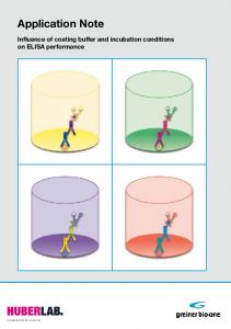
Executing the Reference System The repository folder available for Zynq-7000 AP SoC systems (zc702_GigE folder) contains the latest FreeRTOS BSP which is based out of the latest tool version. To build and execute the socket applications for Zynq-7000 AP SoC devices, create a local repository that contains the FreeRTOS BSP along with lwIP 1.4.1 TCP/IP stack. This BSP is then used by SDK to build the socket applications. To create a local repository in SDK, perform the following. 1. Select Xilinx Tools > Repositories in SDK. A new window pops up. 2. Click the New tab for local repositories. 3. Assuming that the folders are downloaded and put at a Windows location C:\xapp1026\zc702_GigE, the FreeRTOS BSP is present at C:\xapp1026\zc702_GigE\repo\bsp\freertos_zynq_v1_01_a. Browse until C:\xapp1026\zc702_GigE\repo is available. This is the path for the local repository. 4. Click the Rescan Repositories tab. 5. Click the Apply tab. 6. Click the OK tab.
XAPP1026 (v5.1) November 21, 2014
www.xilinx.com
Send Feedback
12
Executing the Reference System X-Ref Target - Figure 1
Figure 1:
Creating a Local Repository for FreeRTOS BSP (Only Applicable for Zynq-7000 AP SoC)
XAPP1026 (v5.1) November 21, 2014
www.xilinx.com
Send Feedback
13
Executing the Reference System
Step 3: Import Software Projects Software platforms and applications can be created in SDK after the hardware platform is specified. Instead of creating a new software platform/application, import the existing software platforms and example applications provided with this reference design using these steps: 1. Select File > Import to open an import wizard. 2. Select General > Existing SDK Projects into Workspace in the import wizard. 3. To select the root directory from which the projects need to be imported, click Browse and specify the location where the software applications are stored. Assuming that the projects are downloaded at Windows C:\xapp1026, for the zc702_GigE design, this Windows location is C:\xapp1026\zc702_GigE\sw folder. 4. The import wizard displays a list of projects that are available to import. This list should include: fsbl (applicable for Zynq-7000 AP SoC devices only and for other systems it does not show up) hw_platform_0, raw_apps, raw_bsp, sock_apps, and sock_bsp. Select all these projects to be imported. Select the option Copy projects into workspace, if you want local copies of these projects in the workspace. Finally select Finish (see Figure 2).
XAPP1026 (v5.1) November 21, 2014
www.xilinx.com
Send Feedback
14
Executing the Reference System X-Ref Target - Figure 2
Figure 2:
Select Folder to Import Projects
5. As soon as the import is done, SDK by default starts building all available software applications. Normally there should be no errors. In case of any build errors, clean all the projects from SDK and then rebuild them. 6. If you get errors even after performing the clean build, implement the following: a. Right-click the application (for example, raw_apps) and click C/C++ Build Settings. A settings window appears.
XAPP1026 (v5.1) November 21, 2014
www.xilinx.com
Send Feedback
15
Executing the Reference System b. At the left-side of this window, select the Project References and disable or uncheck the respective BSP (for example, raw_apps_bsp) and click OK. c. Build the application (for example, raw_apps) again and right-click the application (for example, raw_apps). d. Click Change Referenced BSP and a pop-up window appears. e. Select the respective BSP (for example, raw_apps_bsp) and click OK. 7. If you get errors for socket_apps, use step 6.
Step 4: Download the Bitstream (Only Applicable for MicroBlaze Processor Systems) Using the Xilinx SDK 2014.3, download the bitstream and select Xilinx Tools > Program FPGA to display the Program FPGA dialog box. Ensure that both the design_1_wrapper.bit file and the design_1_wrapper_bd.mmi file locations are proper, and then click Program (see Figure 3). X-Ref Target - Figure 3
Figure 3:
XAPP1026 (v5.1) November 21, 2014
Programming the FPGA with Xilinx SDK 2014.3
www.xilinx.com
Send Feedback
16
Executing the Reference System
Step 5: Download MFS Image The memory file system image contains the files required for the web server to serve files from, and for the TFTP server to store and retrieve files. The image must be downloaded to the onboard DDR memory before the executable can run properly. To download the MFS image for MicroBlaze processor-based systems, select Xilinx Tools > XMD Console. From within the XMD, navigate to the location where the image.mfs file has been placed (in ready_for_download folder). From this location, download the image with the applicable command: •
•
For the AC701_AXI system, use: °
XMD% connect mb mdm
°
XMD% dow -data image.mfs 0xBF000000
For the KC705_AXI system, use: °
XMD% connect mb mdm
°
XMD% dow -data image.mfs 0xBF000000
The preceding procedure does not apply to Zynq-7000 AP SoC devices. For downloading image.mfs for Zynq-7000 AP SoC devices, See the following section (step 6).
Step 6: Create a Run Configuration and Run the Application To run the application, use these steps: 1. Create a run configuration specifying the ELF that needs to be run: a. Select the application that needs to be run. b. To create a Run configuration, select Run > Run Configuration. c. Create a new run configuration by right-clicking the Xilinx C/C++ ELF tab on the left pane. d. Browse and specify the Project details. e. Ensure that the specified ELF is appropriate. If raw_apps is selected (in step a), the ELF should be raw_apps.elf and if socket_apps is selected (in step a), the ELF should be socket_apps.elf. f.
This step applies to the Zynq-7000 AP SoC project. Click the Target Setup tab. Ensure that the path to the initialization Tcl Console file is correct. Assuming that the projects are downloaded to the folder C:\xapp1026 folder and the user workspace name is "myws_GigE" to which all the imported folders are copied, the Tcl Console path should be launched automatically ps7_init.tcl. Similarly click the Application tab and provide the image.mfs. File path and address should be specified properly in the section for Data Files to be downloaded before launch. Ensure that the path specified for this case is C:\xapp1026\zc702_GigE\ready_for_download\image.mfs and the address
XAPP1026 (v5.1) November 21, 2014
www.xilinx.com
Send Feedback
17
Executing the Reference System specified is 0x7200000. See Figure 4 (Run Configurations settings for Zynq-7000 AP SoC devices). 2. Select Apply and Run to run the executable. It might take a while (and a long time for Zynq-7000 AP SoC systems depending on the size of the image.mfs being used) before the ELF (and image.mfs for Zynq-7000 AP SoC devices) is downloaded to hardware and starts running. X-Ref Target - Figure 4
Figure 4:
Run Configuration Settings for Zynq-7000 AP SoC
Important Notes: •
The contents for memfs (and hence image.mfs) are for demonstration purposes and are not updated for ML605/SP605/AC701/KC705/ZC702 boards. They are provided to show that the web server demonstration example works fine.
•
For ML605/SP605/AC701/KC705 systems, the board pictures and hence the location of LEDs and DIP switches are for older Xilinx FPGA boards. However, the LEDs can still be toggled from the host (using the web page). Similarly the DIP switches status show up properly for ML605/SP605/AC701/KC705 boards.
•
For the ZC702 board, the contents for displayed web page are just for demonstration purposes. The pictures of boards are not for the ZC702 board. The LEDs cannot be toggled using the web page. Similarly the ZC702 board does not contain any DIP switches whose status can be shown up on the web page.
XAPP1026 (v5.1) November 21, 2014
www.xilinx.com
Send Feedback
18
Running the .elf from XMD •
For Zynq-7000 AP SoC devices, one more MFS file with the name image_BIG.mfs (of 8 MB size) is also provided. You can rename it to image.mfs and download it at the same location and use the same settings explained previously. This is provided to display the greater speed for Zynq-7000 AP SoC devices. The web pages downloaded through this image.mfs by the host PC are large in size. However, this web page is not suitable for running the TFTP example (as the corresponding memfs file is not part of this application note release).
Running the .elf from XMD You can directly use the files provided in the ready_for_download folder and run them on a relevant board without using SDK to download and run them. Perform the following: 1. Go to the XMD prompt. 2. Go to the ready_for_download folder that contains the download.bit for the relevant board. 3. Execute fpga -f download.bit. This is only applicable for MicroBlaze processor-based systems and is used to program the bitstream. 4. Execute connect mb mdm (for MicroBlaze processors) or connect arm hw (for Zynq-7000 AP SoC devices). 5. For Zynq-7000 AP SoC systems, fsbl needs to be downloaded to configure the MIO and clocks. Execute dow fsbl.elf to download the elf. Execute con to run the fsbl. Execute stop to stop running the fsbl. 6. Download the image.mfs to the appropriate addresses by executing the command dow -data image.mfs appropriate_address. The addresses to which the image.mfs is to be downloaded for MicroBlaze processor-based systems are already specified in step 5 under the section Executing the Reference System. For Zynq-7000 AP SoC devices, the address to which the image.mfs is to be downloaded is 0x7200000. 7. Download the applications by executing dow raw_apps.elf or dow socket_apps.elf. 8. Run the downloaded applications by executing the command con.
XAPP1026 (v5.1) November 21, 2014
www.xilinx.com
Send Feedback
19
Interacting with the Running Software
Interacting with the Running Software The socket mode and the RAW mode applications bundle the following examples into a single executable: echo server, web server, TFTP server, and receive and transmit throughput tests.
Output from the Application After the executable is run, this output appears on the serial port: -----lwIP RAW Mode Demo Application -----Board IP: 192.168.1.10 Netmask : 255.255.255.0 Gateway : 192.168.1.1 auto-negotiated link speed: 1000 Server Port Connect With.. -------------------- ------ -------------------echo server 7 $ telnet 7 rxperf server 5001 $ iperf -c -i 5 -t 100 txperf client N/A $ iperf -s -i 5 -t 100 (on host with IP 192.168.1.100) tftp server 69 $ tftp -i 192.168.1.10 PUT http server 80 Point your web browser to http://192.168.1.10
For the socket mode application, only the first line changes to indicate that it is the socket mode demonstration application. Now you can interact with the application running on the board from the host machine.
Interacting with the Echo Server To connect to the echo server, use the telnet utility program. $ telnet 192.168.1.10 7 Trying 192.168.1.10... Connected to 192.168.1.10. Escape character is '^]'. hello hello world world ^] telnet> quit Connection closed.
If the echo server works properly, any data sent to the board is echoed in response. Some telnet clients immediately send the character to the server and echo the received data back instead of waiting for the carriage return.
XAPP1026 (v5.1) November 21, 2014
www.xilinx.com
Send Feedback
20
Interacting with the Running Software
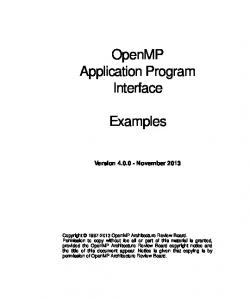
Interacting with the Web Server After the web server is active, it can be connected using a web browser. The sample web pages use Javascript, so the browser must have javascript enabled. A sample web page is shown in Figure 5. The Toggle LED button toggles the state of the LEDs on the board. Clicking the Update Status refreshes the status of the DIP switches on the web page. These show simple control and monitoring of the embedded platform through the web browser. The external links section contains links that point to content that are not served by the development platform. X-Ref Target - Figure 5
X1026_03_060409
Figure 5:
Web Page Served by the Reference Web Server
Interacting with the TFTP Server The TFTP server provides simple file transfer capability to and from the memory file system resident on the board. The following examples use the TFTP client on Windows, and show how to read or write files on the board memory file system from the local host. root@ssw-ubuntu:~#tftp 192.168.1.10 tftp>get index.html Received 2996 bytes in 0.0 seconds tftp>put hello.txt Sent 26393 bytes in 0.0 seconds
Press Ctrl+Z to exit from TFTP.
XAPP1026 (v5.1) November 21, 2014
www.xilinx.com
Send Feedback
21
Interacting with the Running Software
Interacting with the Receive Throughput Test To measure receive throughput, connect to the receive iperf application using the iperf client by issuing the iperf -c command with relevant options. A sample session (with zc702_GigE as reference) is as follows: root@ssw-ubuntu:~# iperf -c 192.168.1.10 -i 5 -t 50 -w 64k -----------------------------------------------------------Client connecting to 192.168.1.10, TCP port 5001 TCP window size: 128 KByte (WARNING: requested 64.0 KByte) -----------------------------------------------------------[ 3] local 192.168.1.100 port 43822 connected with 192.168.1.10 port 5001 [ ID] Interval Transfer Bandwidth [ 3] 0.0- 5.0 sec 560 MBytes 939 Mbits/sec [ 3] 5.0-10.0 sec 562 MBytes 943 Mbits/sec [ 3] 10.0-15.0 sec 562 MBytes 943 Mbits/sec [ 3] 15.0-20.0 sec 562 MBytes 943 Mbits/sec [ 3] 20.0-25.0 sec 562 MBytes 943 Mbits/sec [ 3] 25.0-30.0 sec 562 MBytes 943 Mbits/sec [ 3] 30.0-35.0 sec 562 MBytes 943 Mbits/sec [ 3] 35.0-40.0 sec 562 MBytes 943 Mbits/sec [ 3] 40.0-45.0 sec 562 MBytes 943 Mbits/sec [ 3] 45.0-50.0 sec 562 MBytes 943 Mbits/sec [ 3] 0.0-50.0 sec 5.49 GBytes 942 Mbits/sec
Note: To achieve maximum throughput numbers, ensure that the executable has been compiled for “-O2” optimization level rather than “-O0” optimization. For the Ethernet-Lite systems, use a TCP window size of 8 KB instead of 64 KB to receive maximum performance numbers.
Interacting with the Transmit Throughput Test To measure the transmit throughput, start the iperf server on the host, and then run the executable on the board. When the executable is run, it attempts to connect to a server at host 192.168.1.100. This address can be changed in the txperf.c file. A sample session (with zc702_GigEas reference) host PC as Ubuntu is as follows: root@ssw-ubuntu:~# iperf -s -i 5 -w 64k -----------------------------------------------------------Server listening on TCP port 5001 TCP window size: 128 KByte (WARNING: requested 64.0 KByte) -----------------------------------------------------------[ 4] local 192.168.1.100 port 5001 connected with 192.168.1.10 port 49153 [ ID] Interval Transfer Bandwidth [ 4] 0.0- 5.0 sec 563 MBytes 944 Mbits/sec [ 4] 5.0-10.0 sec 566 MBytes 949 Mbits/sec [ 4] 10.0-15.0 sec 566 MBytes 949 Mbits/sec [ 4] 15.0-20.0 sec 566 MBytes 949 Mbits/sec [ 4] 20.0-25.0 sec 566 MBytes 949 Mbits/sec [ 4] 25.0-30.0 sec 566 MBytes 949 Mbits/sec [ 4] 30.0-35.0 sec 566 MBytes 949 Mbits/sec [ 4] 35.0-40.0 sec 566 MBytes 949 Mbits/sec [ 4] 40.0-45.0 sec 566 MBytes 949 Mbits/sec [ 4] 45.0-50.0 sec 566 MBytes 949 Mbits/sec
Press Ctrl+C twice to stop the server. Note: For the Ethernet-Lite systems, use a TCP window size of 8 KB instead of 64 KB to receive maximum performance numbers.
XAPP1026 (v5.1) November 21, 2014
www.xilinx.com
Send Feedback
22
lwIP Performance
lwIP Performance The receive and transmit throughput applications are used to measure the maximum TCP throughput possible with lwIP using the Xilinx Ethernet adapters. Table 2 summarizes the results for different configurations. Depending upon different cache configurations, the performance numbers can vary. Table 2:
TCP Performance Numbers
Hardware Design Name
RAW Mode
Socket Mode
RX (Mb/s)
TX (Mb/s)
RX (Mb/s)
TX (Mb/s)
AC701_AxiEth_32kb_Cache
205
125
37
41
AC701_AxiEth_64kb_Cache
270
175
40
46.8
KC705_AxiEth_32kb_Cache
290
190
52.9
56.2
KC705_AxiEth_64kb_Cache
380
250
58.4
69.5
KC705_AxiEthernetlite_64kb_Cache
46
67
29
44
ZC702_GigE
943
949
521
542
These performance numbers were obtained under these conditions: •
When measuring receive throughput, only the receive throughput application was enabled (in file config_apps.h). This also applies to the transmit throughput test.
•
The host machine was Dell desktop running Windows 7. The NIC card used on the host was an Intel 82566DM-2 Gigabit Ethernet Controller card.
•
The performance numbers for RAW Mode TX for MicroBlaze processor-based systems were obtained using zero-copy pbufs.
Note: The RAW mode TX performance numbers for MicroBlaze processor systems were obtained using zero-copy pbufs. Zero-copy pbuf means that lwIP stack is not copying the user buffer to a pbuf and a reference to the user buffer is used instead of copying it. The assumption here is that until the point the corresponding Ethernet frame is transmitted out and pbuf is freed up, you are not going to alter the contents of this buffer. For the given TX perf applications it is not an issue and hence zero-copy pbufs are used. This avoids a copy of the buffer and hence improves performance. For Zynq-7000 AP SoC systems, the RAW mode TX performance is already High and using a zero-copy pbuf does not really give a significant improvement. Hence for Zynq-7000 AP SoC systems, zero-copy pbufs are not used. All other RAW mode applications (echo server, web server, and TFTP server) do not use the zero-copy pbuf feature. Also, for socket mode applications there is no provision for zero-copy pbufs. For MicroBlaze processor-based RAW mode TX perf applications, you can change the source code in file txperf.c to avoid using zero-copy pbufs. This can be done by ensuring that when a tcp_write is called, the third argument passed has a value of 3 instead of 0 (present by default for MicroBlaze processor-based systems). Note: By making this change, you might need to revisit the lwIP 1.4.1 settings in the BSP. For information on how to optimize the host setup, and benchmarking TCP in general, see Measuring Treck TCP/IP Performance Using the XPS LocalLink TEMAC in an Embedded Processor System (XAPP1043) [Ref 4].
XAPP1026 (v5.1) November 21, 2014
www.xilinx.com
Send Feedback
23
DHCP Support
DHCP Support All applications published as part of this document are built with Dynamic Host Configuration Protocol (DHCP) support. The applications assume that there is a DHCP server available in the network that assigns an IP address to the relevant board. However, if a DHCP server is not available in the network to which the board is connected, a DHCP timeout occurs after a while. Upon a DHCP timeout a static IP address of 192.168.1.10 is assigned to the relevant board. In a typical case when a user PC (which does not have a DHCP server running on it) is connected back-to-back to any of the boards supported in this application note, a DHCP timeout occurs and a static IP of 192.168.1.10 is assigned to the board. You can run all the available applications specified previously in this application note on the host PC (assumed to have an IP address of 192.168.1.100). If you want to run iperf on a host PC connected to a LAN (which has a DHCP server) to which the relevant board is connected, a small change is needed in the file txperf.c. The current implementations of txperf.c assume that the iperf server has an IP address of 192.168.1.100. This address needs to be changed appropriately in file txperf.c. Finally, you can disable the DHCP server in the applications by altering the lwIP 1.4.1 settings in the relevant BSPs.
JUMBO Frame Support All MicroBlaze/AXI Ethernet systems available as part of this application note are built with jumbo frame support. However, you need to change some of the BSP settings for lwIP 1.4.1 (on top of the existing settings provided in the BSPs in this application note) to actually send jumbo frames. •
Change the value of the lwip140 parameter "temac_use_jumbo_frames" under the category "temac_adapter_options" to TRUE.
•
Change the value of the lwIP 1.4.1 parameter "pbuf_pool_bufsize" under the category "pbuf_options" from the default 1700 to 9700.
•
Change the value of the lwIP 1.4.1 parameter "ip_reass_bufsize" under the category "lwip_ip_options" from the default 5760 to 65535.
•
Change the value of the lwIP 1.4.1 parameter "ip_frag_max_mtu" under the category "lwip_ip_options" from the default 1500 to 9000.
•
Change the value of the lwIP 1.4.1 parameter "tcp_mss" under the category "tcp_options" from the default 1460 to 8060.
•
Change the value of the lwIP 1.4.1 parameter "mem_size" under the category "lwip_memory_options" from the default 131072 to 524288.
XAPP1026 (v5.1) November 21, 2014
www.xilinx.com
Send Feedback
24
Debugging Network Issues To measure iperf performance numbers (with a host PC connected back-to-back with the relevant board), perform the following: •
Ensure that jumbo frame support is enabled on the host PC NIC card/driver.
•
To run iperf server on the host PC, you must execute the command "iperf -s -i 5 -l 65535 -w 1048576 -M 8060
•
To run iperf client on the host PC, you must execute the command "iperf -c 192.168.1.10 -i 5 -t 50 -w 64k -M 8060 -l 128k
•
The RAW and socket mode applications provided in the respective folders for hardware systems do not need to be changed for performance measurement using jumbo frame support. The necessary changes related to jumbo frames are already present.
Debugging Network Issues If any of the sample applications do not work, there could be several potential reasons. This section provides a troubleshooting guide to fix common sources of setup errors. 1. First, ensure that the link lights are active. Most development boards have LEDs that indicate whether an Ethernet link is active. If the bitstream downloaded has some Ethernet MAC properly configured, and a Ethernet cable is attached to the board, the link lights should indicate an established Ethernet link. 2. If the board includes LEDs indicating the link speed (10/100/1000 Mb/s), verify that the link is established at the correct speed. For designs that include axi_ethernetlite Ethernet MAC IP, the link should be established at only 10 or 100 Mb/s. The axi_ethernetlite cannot transmit or receive data at 1000 Mb/s. The axi_ethernet Ethernet MAC core supports all three link speeds. The TEMAC must be informed of the correct speed to which the PHY has auto-negotiated. lwIP includes software to detect the PHY speed, however this software works only for Marvell PHYs. Confirm that the link speed that lwIP detects matches the link speed as shown in the LEDs. 3. To confirm that the board actually receives packets, a simple test is to ping the board and check to make sure that the RX LED goes High for a moment to indicate that the PHY actually received the packet. If the LEDs do not go High, then there are either ARP, IP, or link level issues that prevent the host from sending packets to the board. 4. Assuming that the board receives the packets, but the system does not respond to ping requests, the next step is to ensure that lwIP actually receives these packets. This can be determined by setting breakpoints at XemacLite_InterruptHandler for axi_ethernetlite systems, axi_dma_recv_handler for axi_ethernet systems, and emacps_recv_handler for Zynq-7000 AP SoC systems. If packets are received properly, then these breakpoints should be hit for every received packet. If these breakpoints are not hit, then that indicates that the MAC is not receiving the packets. This could mean that the packets are being dropped at the PHY. The most common reason that the breakpoints are not hit is that the link was established at a speed that the Ethernet MAC does not support.
XAPP1026 (v5.1) November 21, 2014
www.xilinx.com
Send Feedback
25
Conclusion 5. Finally, some hosts have firewalls enabled that could prevent receiving packets back from the network. If the link LEDs indicate that the board is receiving and transmitting packets, yet the packets transmitted by the board are not received in the host, then the host firewall settings should be relaxed. When these applications are ported over to a different board or hardware, ensure there is sufficient heap and stack space available (as specified in the linker script).
Conclusion This application note showcases how lwIP can be used to develop networked applications for embedded systems on Xilinx FPGAs and Xilinx Zynq-7000 AP SoC systems. The echo server provides a simple starting point for networking applications. The web server application shows a more complex TCP-based application and the TFTP server shows a complex UDP-based application. Applications to measure receive and transmit throughput provide an indication of the maximum possible throughput using lwIP with Xilinx adapters.
Reference Design Included with this application note are AXI4-based reference systems for the Xilinx Arttix-7 AC701 and Kintex-7 KC705 FPGA Starter Kit boards. Also included are Zynq-7000 AP SoC reference systems for the Xilinx ZC-702 boards. To access these reference systems, click the following link: https://secure.xilinx.com/webreg/clickthrough.do?cid=107743.zip
Appendix A: ML605 and SP605 Design Information This appendix provides a summary of the previously released XAPP1026 (v3.2), October 28, 2012 for ISE Design flow. This section highlights the ISE design files for ML605 and SP605 devices and their performance numbers. These design files are provided just for reference, lwIP TCP/IP stack for these devices are not updated to lwIP 1.4.1.
Hardware and Software Requirements The hardware and software requirements are: •
One of the Xilinx Virtex®-6 ML605 or Spartan®-6 SP605 boards for MicroBlaze processor-based systems
•
Xilinx Platform Studio 14.3 for generating hardware modifications for ML605 and SP605
•
Xilinx SDK 14.3 for running or creating hardware modifications to the software for ML605 and SP605
XAPP1026 (v5.1) November 21, 2014
www.xilinx.com
Send Feedback
26
Appendix A: ML605 and SP605 Design Information
Reference System Specifics The reference design for this application note is structured as follows: •
ml605_AxiEth_8Kb_Cache, ml605_AxiEth_32kb_Cache, sp605_AxiEth_8kb_Cache, sp605_AxiEth_32kb_Cache, sp605_EthernetLite_8kb_Cache and sp605_EthernetLite_32kb_Cache folders correspond to the various supported boards and hardware designs for ML605 and SP605.
•
In each folder, the HW subdirectory contains the XPS 14.3 for ML605 and SP605 hardware design. The SW subdirectory contains the application software and software platforms that need to be imported into SDK.
Hardware Systems For ML605 and SP605 hardware systems, the available boards were built using Base System Builder (BSB) with minor modifications in XPS. Table 3 provides a summary of the hardware designs for the available boards. Table 3:
Hardware Design Details
Hardware Design Name
Processor
Processor Frequency
Ethernet Controller
DMA
ML605_AxiEth_8kb_Cache
MicroBlaze
100 MHz
axi_ethernet
axi_dma
ML605_AxiEth_32kb_Cache
MicroBlaze
100 MHz
axi_ethernet
axi_dma
SP605_AxiEth_8kb_Cache
MicroBlaze
100 MHz
axi_ethernet
axi_dma
SP605_AxiEth_32kb_Cache
MicroBlaze
100 MHz
axi_ethernet
axi_dma
SP605_EthernetLite_8kb_Cache
MicroBlaze
75 MHz
axi_ethernetlite
None
SP605_EthernetLite_32kb_Cache
MicroBlaze
75 MHz
axi_ethernetlite
None
Notes: 1. All axi_ethernet-based systems are built with full checksum (both TCP and IP checksums) offload feature. 2. The AXI Ethernet-Lite-based systems are built with ping-pong buffers (one more buffer for both TX and RX paths to improve performance).
Executing the Reference System See the same section explained (Executing the Reference System, page 10) for Artix-7 and Kintex-7 devices with the following changes in Compiling and Running the Software, page 11 at Step 4: Download the Bitstream (Only Applicable for MicroBlaze Processor Systems), page 16 and Step 5: Download MFS Image, page 17.
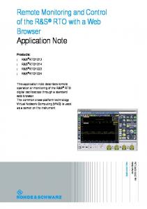
Step 4: Download the Bitstream (Only Applicable for MicroBlaze Processor Systems) Using XPS 14.3, download the bitstream and select Xilinx Tools > Program FPGA to display the Program FPGA dialog box. Ensure that both the system.bit file and the system_bd.bmm file locations are proper, and then click Program (see Figure 6).
XAPP1026 (v5.1) November 21, 2014
www.xilinx.com
Send Feedback
27
Appendix A: ML605 and SP605 Design Information X-Ref Target - Figure 6
Figure 6:
Programming the FPGA with XPS 14.3
Step 5: Download MFS Image From this location, download the image with the applicable command: •
•
For the ML605_AXI system, use: °
XMD% connect mb mdm
°
XMD% dow -data image.mfs 0xDF000000
For the SP605_AXI system, use: °
XMD% connect mb mdm
°
XMD% dow -data image.mfs 0xAF000000
To create a new mfs image, see the following procedure: To create an mfs image from the contents of a folder (memfs), use the relevant command from the SDK bash shell. To open a SDK bash shell, select Xilinx Tools > Launch Shell. At the command prompt, use the appropriate commands to go to the memfs directory. $ mfsgen -cvbf ../image.mfs 2048 css images js yui generate-mfs index.html ****** ****** **** **
xilmfs SDK v2014.3 (64-bit) SW Build 1018564 on Mon Sep 15 18:49:35 MDT 2014 Copyright 1986-2014 Xilinx, Inc. All Rights Reserved. css: main.css 744 images: board.jpg 44176 favicon.ico 2837 logo.gif 1148 js: main.js 7336
XAPP1026 (v5.1) November 21, 2014
www.xilinx.com
Send Feedback
28
Appendix A: ML605 and SP605 Design Information yui: anim.js 12580 conn.js 11633 dom.js 10855 event.js 14309 yahoo.js 5354 generate-mfs 34 index.html 2383 MFS block usage (used / free / total) = 233 / 1815 / 2048 Size of memory is 1089536 bytes Block size is 532 mfsgen done!
lwIP Performance The receive and transmit throughput applications are used to measure the maximum TCP throughput possible with lwIP using the Xilinx Ethernet adapters. Table 4 summarizes the results for different configurations. Depending upon different cache configurations, the performance numbers can vary. Table 4:
TCP Performance Numbers
Hardware Design Name
RAW Mode
Socket Mode
RX (Mb/s)
TX (Mb/s)
RX (Mb/s)
TX (Mb/s)
ML605_AxiEth_8kb_Cache
142
95
32
37
ML605_AxiEth_32kb_Cache
204
170
42
52
SP605_AxiEth_8kb_Cache
137
91
31
35
SP605_AxiEth_32kb_Cache
200
165
39
50
SP605_EthernetLite_8kb_Cache
37
28
18
19
SP605_EthernetLite_32kb_Cache
52
35
22
24
These performance numbers were obtained under these conditions: •
When measuring receive throughput, only the receive throughput application was enabled (in file config_apps.h). This also applies to the transmit throughput test.
•
The host machine was Dell desktop running Windows 7. The NIC card used on the host was an Intel 82566DM-2 Gigabit Ethernet Controller card.
•
The performance numbers for RAW Mode TX for MicroBlaze processor-based systems were obtained using zero-copy pbufs.
Note: The RAW mode TX performance numbers for MicroBlaze processor systems were obtained using zero-copy pbufs. Zero-copy pbuf means that lwIP stack is not copying the user buffer to a pbuf and a reference to the user buffer is used instead of copying it. The assumption here is that until the point the corresponding Ethernet frame is transmitted out and pbuf is freed up, you are not going to alter the contents of this buffer. For the given TX perf applications it is not an issue and hence zero-copy pbufs are used. This avoids a copy of the buffer and hence improves performance. For MicroBlaze processor-based RAW mode TX perf applications, you can change the source code in file txperf.c to avoid using zero-copy pbufs. This can be done by ensuring that when a tcp_write is called, the third argument passed has a value of 3 instead of 0 (present by default for MicroBlaze processor-based systems).
XAPP1026 (v5.1) November 21, 2014
www.xilinx.com
Send Feedback
29
References
References 1. lwIP – A Lightweight TCP/IP Stack – CVS Repositories 2. RFC 1350 – The TFTP Protocol 3. iperf software 4. Measuring Treck TCP/IP Performance Using the XPS LocalLink TEMAC in an Embedded Processor System (XAPP1043)
Revision History This table shows the revision history for this document: Date
Version
11/21/2014
5.1
Revision • Added KC705_AxiEthernetlite_64kb_Cache support. • Updated Table 1: Hardware Design Details. • Updated/added Note in Interacting with the Receive and Transmit Throughput Test sections. • Updated Table 2: TCP Performance Numbers.
10/24/2014
5.0
• Added Kintex, and Artix support. • Added Appendix A for Virtex and Spartan information.
08/14/2014
4.0
• Updated to latest template. • Updated to latest SDK 2014.2, lwIP 1.4.1. • Updated Figs. 1 to 4. • Updated Interacting with the Receive Throughput Test section. • Updated lwIP Performance section.
10/28/2012
3.2
• Updated for Zynq-7000 AP SoC support • Added sections for DHCP and jumbo support • Added a section for using the files in ready_for_download folder from XMD without using SDK • Updated performance numbers for provided systems.
04/21/2011
3.1
Updated “Compiling and Updating the Software” section and Appendix A.
03/20/2011
3.0
Updated for AXI4 interface. Updated block size for mfsgen command from 1500 to 2012 to prevent errors.
06/15/2009
2.0
Updated to v2.0 for IDS11.1.
10/13/2008
1.0
Initial Xilinx release.
XAPP1026 (v5.1) November 21, 2014
www.xilinx.com
Send Feedback
30
Please Read: Important Legal Notices
Please Read: Important Legal Notices The information disclosed to you hereunder (the "Materials") is provided solely for the selection and use of Xilinx products. To the maximum extent permitted by applicable law: (1) Materials are made available "AS IS" and with all faults, Xilinx hereby DISCLAIMS ALL WARRANTIES AND CONDITIONS, EXPRESS, IMPLIED, OR STATUTORY, INCLUDING BUT NOT LIMITED TO WARRANTIES OF MERCHANTABILITY, NON-INFRINGEMENT, OR FITNESS FOR ANY PARTICULAR PURPOSE; and (2) Xilinx shall not be liable (whether in contract or tort, including negligence, or under any other theory of liability) for any loss or damage of any kind or nature related to, arising under, or in connection with, the Materials (including your use of the Materials), including for any direct, indirect, special, incidental, or consequential loss or damage (including loss of data, profits, goodwill, or any type of loss or damage suffered as a result of any action brought by a third party) even if such damage or loss was reasonably foreseeable or Xilinx had been advised of the possibility of the same. Xilinx assumes no obligation to correct any errors contained in the Materials or to notify you of updates to the Materials or to product specifications. You may not reproduce, modify, distribute, or publicly display the Materials without prior written consent. Certain products are subject to the terms and conditions of Xilinx's limited warranty, please refer to Xilinx's Terms of Sale which can be viewed at http://www.xilinx.com/legal.htm#tos; IP cores may be subject to warranty and support terms contained in a license issued to you by Xilinx. Xilinx products are not designed or intended to be fail-safe or for use in any application requiring fail-safe performance; you assume sole risk and liability for use of Xilinx products in such critical applications, please refer to Xilinx's Terms of Sale which can be viewed at http://www.xilinx.com/legal.htm#tos. © Copyright 2008–2014 Xilinx, Inc. Xilinx, the Xilinx logo, Artix, ISE, Kintex, Spartan, Virtex, Vivado, Zynq, and other designated brands included herein are trademarks of Xilinx in the United States and other countries. All other trademarks are the property of their respective owners.
XAPP1026 (v5.1) November 21, 2014
www.xilinx.com
Send Feedback
31