Boise State University
ScholarWorks Electrical and Computer Engineering Faculty Publications and Presentations
Department of Electrical and Computer Engineering
1-1-2009
Lyapunov Stability of an Open-Loop Induction Machine Ahmed Oteafy Boise State University
John Chiasson Boise State University
©2008 IEEE. Personal use of this material is permitted. However, permission to reprint/republish this material for advertising or promotional purposes or for creating new collective works for resale or redistribution to servers or lists, or to reuse any copyrighted component of this work in other works must be obtained from the IEEE. DOI: 10.1109/ACC.2009.5160421
2009 American Control Conference Hyatt Regency Riverfront, St. Louis, MO, USA June 10-12, 2009
ThC07.2
Lyapunov Stability of an Open-Loop Induction Machine Ahmed Oteafy, Graduate Student Member, IEEE, and John Chiasson, Senior Member, IEEE
Abstract— The induction machine is widely utilized in the industry and exists in a plethora of applications. Although it is characterized by its inherent stability over a wide range of operating conditions, this characterization is based on steadystate arguments. This work develops a rigorous approach to the open-loop stability of the induction machine. In particular, a condition for the global asymptotic stability of the induction machine in the sense of Lyapunov is presented. These conditions are met if the machine is lightly loaded. Hence, meeting these conditions guarantees that the motor will reach (or return to) the desired equilibrium point regardless of how far it has been perturbed from it. The analysis is based on the standard nonlinear differential equation model of the induction machine taking into account transient responses. Index Terms— Induction Machine, Lyapunov Stability, OpenLoop Stability
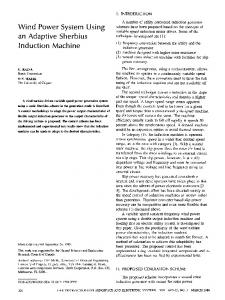
I. I NTRODUCTION The classical method that depicts the range of stable operation for the induction machine is a torque versus (normalized) slip curve as shown below (see [1])
pull-out slip which corresponds to the peak torque τ p . The curve indicates the stability of the induction machine about steady-state operating points. The stable steady-state operating points for motoring must satisfy 0 < S < Sp . For example, if the motor is operating at slip S1 producing the torque τ 0 as shown in Figure 1. Then any increase in the load torque (but the total load torque not exceeding τ p ) would result in a decrease in the steady-state speed ω R [see (1)] with a consequent increase in the steady-state slip S (i.e. a shift to the right from the operating point S1 in Figure 1). The increased slip gives an increase in the steady-state output torque to accommodate the increase in the load torque. On the other hand, consider the motor operating at the slip S2 > Sp in Figure 1. Any increase in the load torque (even a minimal one) would again result in a decrease in ω R [see (1)] and thus an increased slip to the right of the original steady-state slip S2 in Figure 1. But now a lower output torque is produced which cannot meet the increased load demand. Hence the motor will stall. Note that this argument is based on steady-state conditions and does not account for transients. In fact though the operating points for S > Sp are always unstable, operating points with S < Sp can also be unstable. At rest (ω R = 0), S = 1 and typically Sp > Sp and, as Figure 1 shows, the torque produced by the motor is low. As a result, the machine must be lightly loaded so that it can come up to full (near synchronous) speed under open-loop conditions. After getting up to full speed, the motor can then be loaded and run stably.
Fig. 1.
Torque versus normalized slip curve
τ is the steady state output torque, τ p is the peak load torque, S is the normalized slip defined as ω S − np ω R S, (1) ωS (i.e. the normalized difference between the electrical frequency ω S , and the angular speed np ω R ), and Sp is the A. Oteafy is with the ECE Department, Boise State University, Boise ID 83725,
[email protected]. J. Chiasson is with the ECE Department, Boise State University, Boise ID 83725,
[email protected].
978-1-4244-4524-0/09/$25.00 ©2009 AACC
In this work, we give a rigorous treatment of the stability issue by accounting for transients. Specifically, a sufficient condition for the global stability of an open-loop induction machine is derived using Lyapunov theory based on the wellknown nonlinear differential equation model of the induction machine. It is shown that the conditions for global stability hold if the machine is lightly loaded. We begin in Section II by deriving an error-dynamics model of the induction motor in the stator field coordinate system. In Section III a power balance equation of the motor is developed that is then transformed into the error state variables. The results are then utilized in Section IV to develop a Lyapunov function that gives sufficient conditions for global stability of the induction machine. Section V provides a numerical example that is used to demonstrate the application of the theorem. Finally, concluding remarks are presented in Section VI.
3452
Authorized licensed use limited to: Boise State University. Downloaded on May 10,2010 at 20:20:47 UTC from IEEE Xplore. Restrictions apply.
II. S TATOR F IELD M ODEL OF THE I NDUCTION M OTOR The starting point for the analysis is the two-phase equivalent model of the machine (see [1] and [2]). The parameters of the two phase induction motor are the stator-side inductance LS and resistance RS , the rotor-side inductance LR and resistance RR , the mutual inductance M , the number of rotor pole pairs np , the moment of inertia of the rotor J, and the rotational friction f . The variables consist of the angular position of the rotor θR , the angular speed ω R , the load torque τ L , the stator currents iSa and iSb , the stator voltages uSa and uSb , and the rotor currents iRa and iRb where a and b denote the equivalent two phases of the motor. A. Space Vector Model A space vector model of the induction machine is ([1] and [2]) d d ¡ jnp θR ¢ = uS iS + M i e dt dt R d ¡ −jnp θR ¢ d RR iR + LR iR + M = 0 (2) i e dt dt S n ¡ o ¢∗ dω R np M Im iS iR ejnp θR − τL = J dt where the state vector’s (complex) stator current, rotor current and stator voltage are defined as
Substituting (4) into the space vector model (2) and simplifying results in diRdq diSdq + jω S LS iSdq + M dt dt +jω S M iRdq = uSdq
RS iSdq + LS
RR iRdq + LR +M
n ¡ ¢∗ o dω R np M Im iSdq iRdq − (f ω R + τ L0 ) = J dt Expanding into real and imaginary parts, we obtain the state space representation
where
τ L , f ω R + τ L0 where τ L0 denotes the external load torque exerted on the rotor, and is henceforth assumed to be constant. B. Stator Field Coordinate System Model Next, the model (2) is transformed into a stator field coordinate system. The transformation is defined as
iRdq
, iRd + jiRq , iR ejnp θR e−jωS t
uSdq
, uSd + juSq , uS e−jωS t
, iS e−jωS t (3)
or iS
= iSdq ejωS t
iR
= iRdq e−jnp θR ejωS t
uS
= uSdq e
x , u , ⎡
The total load torque on the motor τ L is defined as
, iSd + jiSq
(6)
x˙ = f (x) + Bu
, iSa + jiSb , iRa + jiRb , uSa + juSb
iSdq
(5)
diSdq + j (ω S − np ω R ) M iSdq = 0 dt
RS iS + LS
iS iR uS
diRdq + j (ω S − np ω R ) LR iRdq dt
(4)
jω S t
where ω S is the electrical frequency of the voltage source applied to the stator and is assumed to be constant. 3453
⎢ ⎢ ⎢ ⎢ ⎢ ⎢ ⎢ ⎢ ⎢ ⎢ ⎢ ⎢ ⎢ ⎢ ⎢ ⎢ ⎢ f (x) , ⎢ ⎢ ⎢ ⎢ ⎢ ⎢ ⎢ ⎢ ⎢ ⎢ ⎢ ⎢ ⎢ ⎢ ⎢ ⎢ ⎢ ⎣
£
£
ωR
iSd
uSd
uSq
iSq τ L0
iRd ¤T
iRq
¤T
np M f (iSq iRd − iSd iRq ) − ω R J J np M RS RR M iRd + ω R iRq − iSd σLS LR σLS σLS 2 np M + ω R iSq + ω S iSq σLS LR np M RS RR M iRq − ω R iRd − iSq σLS LR σLS σLS 2 np M − ω R iSd − ω S iSd σLS LR np M RR RS (1 − σ) ω R iSq − iRd iSd − σM σLR σLR np − ω R iRq + ω S iRq σ np M RR RS (1 − σ) ω R iSd − iRq iSq + σM σLR σLR np + ω R iRd − ω S iRd σ ⎡ ⎤ 1 0 0 − ⎢ J ⎥ ⎢ ⎥ 1 ⎢ 0 0 ⎥ ⎢ σLS ⎥ ⎢ ⎥ 1 ⎢ ⎥ B,⎢ 0 0 ⎥ ⎢ ⎥ σL S ⎢ σ−1 ⎥ ⎢ 0 0 ⎥ ⎢ σM ⎥ ⎣ ⎦ σ−1 0 0 σM
Authorized licensed use limited to: Boise State University. Downloaded on May 10,2010 at 20:20:47 UTC from IEEE Xplore. Restrictions apply.
⎤ ⎥ ⎥ ⎥ ⎥ ⎥ ⎥ ⎥ ⎥ ⎥ ⎥ ⎥ ⎥ ⎥ ⎥ ⎥ ⎥ ⎥ ⎥ ⎥ ⎥ ⎥ ⎥ ⎥ ⎥ ⎥ ⎥ ⎥ ⎥ ⎥ ⎥ ⎥ ⎥ ⎥ ⎥ ⎦
and σ is the leakage factor defined as
A(x0 ) ,
M2 . LS LR The equilibrium conditions are obtained by setting the derivatives in the stator field model (5) to zero and then equating the real and imaginary parts to obtain
⎡
−f ¢ ⎢ np (σ−1) ¡ LRJ i + iSq0 ⎢ − σ ⎢ np (σ−1) ¡ LM Rq0 ¢ R ⎢ σ ³ M iRd0 + iSd0 ⎢ ´ ⎢ n ⎢ − σp LMR iSq0 + iRq0 ⎣ ³ ´ np M σ LR iSd0 + iRd0
σ ,1−
RS iSd0 − ω S LS iSq0 − ω S M iRq0 = uSd0
np M J iRd0 np (σ−1) − σ ω R0 + RS − σL S np M − σLR ω R0 (σ−1) − RSσM
RS iSq0 + ω S LS iSd0 + ω S M iRd0 = uSq0
RR iRd0 −ω S LR iRq0 + np ω R0 LR iRq0 −ω S M iSq0 +np ω R0 M iSq0 = 0
(7)
ωS
and
np M (iSq0 iRd0 − iSd0 iRq0 ) − (f ω R0 + τ L0 ) = 0
C. Error Model
e1 e2 e3 e4 e5
, , , , ,
or ωR iSd iSq iRd iRq
= = = = =
ω R − ω R0 iSd − iSd0 iSq − iSq0 iRd − iRd0 iRq − iRq0
⎡
e1 + ω R0 e2 + iSd0 e3 + iSq0 e4 + iRd0 e5 + iRq0 .
e2
e3
e4
where K , (9)
⎤
⎥ ⎥ ⎥ ⎥ ⎥ ⎥ ⎥. ⎥ ⎥ ⎥ ⎥ ⎥ ⎦
(12)
(13)
¤T
⎤ ⎡ iSd0 uSd0 ⎢ iSq0 ⎥ ⎢ uSq0 ⎥ ⎢ K⎢ ⎣ iRd0 ⎦ = ⎣ 0 0 iRq0
⎤ ⎥ ⎥ ⎦
(14)
⎡
RS −ω S LS ω S LS RS 0 M (np ω R0 − ω S ) −M (np ω R0 − ω S ) 0 0 −ω S M ωS M 0 RR LR (np ω R0 − ω S ) −LR (np ω R0 − ω S ) RR
⎢ ⎢ ⎣
(10)
e5
(11)
⎥ ⎥ ⎥ ⎥ ⎥ ⎥ ⎦
np M (iSq0 iRd0 − iSd0 iRq0 ) − (f ω R0 + τ L0 ) = 0
where e1
np M J iSd0 np M σLS ω R0 RR M σLS LR n ω S − σp ω R0 RR − σL R
−
⎤
(8)
e˙ = A(x0 )e+g(e) £
ωS
The error model consists of quadratic terms which vanish near the equilibrium point (where the matrix A(x0 ) dominates), and the stability of the linearized system is dependent on the choice of the equilibrium point as A(x0 ) depends on the equilibrium point. The system (7) which determines the equilibrium points may be rewritten as
Then, substituting these expressions for the state variables of the stator field into the model (6), we obtain the error model of the induction machine
e=
np M J iSq0 RR M σLS LR np M − σL ω R0 S RR − σL R np σ ω R0 − ω S
⎡ n M np M p e e − e2 e5 ⎢ J 3 4 J ⎢ np M np M 2 ⎢ ⎢ σL e1 e5 + σL L e1 e3 ⎢ S S R ⎢ np M np M 2 g(e) , ⎢ ⎢ − σL e1 e4 − σL L e1 e2 S S R ⎢ ⎢ np M np ⎢ − e e − e 1 3 1 e5 ⎢ σLR σ ⎣ n M np p e1 e2 + e1 e4 σLR σ
RR iRq0 + ω S LR iRd0 − np ω R0 LR iRd0 + ω S M iSd0 −np ω R0 M iSd0 =0
Next, to facilitate the Lyapunov analysis of the induction machine we derive an error model. This is achieved by translating the origin of the system (6) to an arbitrary equilibrium point x0 as defined by (7). Specifically, a set of error state variables about an equilibrium point is defined as
np M J iRq0 RS − σL S np (σ−1) ω R0 − σ (σ−1) − RSσM np M σLR ω R0
−
⎤
⎥ ⎥. ⎦
Therefore, one possible scenario is to select the setpoints for the speed ω R0 , and voltages uSd0 and uSq0 , with the currents iSd0 , iSq0 , iRd0 and iRq0 then specified by 3454
Authorized licensed use limited to: Boise State University. Downloaded on May 10,2010 at 20:20:47 UTC from IEEE Xplore. Restrictions apply.
equation (14). The resulting load torque τ L0 is determined by equation (13). In other words, one specifies ω R0 , uSd0 and uSq0 , and then uses ⎡ ⎤ ⎡ ⎤ iSd0 uSd0 ⎢ iSq0 ⎥ ⎢ ⎥ −1 ⎢ uSq0 ⎥ ⎢ ⎥ (15) ⎣ iRd0 ⎦ = K ⎣ 0 ⎦ 0 iRq0
Wf
and
=
¡ ¢ 1 LS e22 + e23 + 2e2 iSd0 + 2e3 iSq0 2 ¡ ¢ 1 + LR e24 + e25 + 2e4 iRd0 + 2e5 iRq0 + M e2 e4 2 +M (iSd0 e4 + e2 iRd0 + e3 e5 + iSq0 e5 + e3 iRq0 ) ¡ ¢ 1 ¡ ¢ 1 + LS i2Sd0 + i2Sq0 + LR i2Rd0 + i2Rq0 2 2 +M (iSd0 iRd0 + iSq0 iRq0 )
and τ L0 = np M (iSq0 iRd0 − iSd0 iRq0 ) − f ω R0
(16)
¢ 1 1 ¡ 2 J e1 + 2e1 ω R0 + Jω 2R0 . 2 2 IV. LYAPUNOV S TABILITY OF THE I NDUCTION M ACHINE WJ =
to obtain the currents and load torque. III. P OWER BALANCE E QUATION The Lyapunov candidate function will be derived from a power balance equation that characterizes the power transfer between the input and output of the motor.
In this section, the power balance equation (20) is used to obtain a Lyapunov candidate function V . Define the function W (e) by W (e) , Wf + WJ − (Wf (0) + WJ (0))
A. Power Balance Equation First we define the magnetic field energy of the motor Wf and the mechanical energy WJ as (see [1]) Wf
and
,
¡ ¢ 1 ¡ ¢ 1 LS i2Sd + i2Sq + LR i2Rd + i2Rq 2 2 ¸ ∙ £ ¤ iRd +M iSd iSq (17) iRq WJ ,
1 2 Jω . 2 R
(18)
where Wf (0) = and WJ (0) =
£ d (Wf + WJ ) = uSd dt
uSq
−τ L
¤
⎤
iSd ⎣ iSq ⎦ ωR
W (e) = eTP e + dT e
(21)
where ⎡
(19)
−RS i2Sd − RS i2Sq − RR i2Rd − RR i2Rq .
B. Error State Variables Next, substituting for the state variables (7) of the stator field into the power balance equation (19), and simplifying using the equilibrium conditions (7) results in the power balance equation given in terms of the error state variables as d (Wf + WJ ) = uSd e2 + uSq e3 dt ¡ ¢ − f e21 + 2f e1 ω R0 + τ L0 e1 (20) ¡ 2 ¢ ¡ 2 ¢ − RS e2 + 2e2 iSd0 − RS e3 + 2e3 iSq0 ¡ ¢ ¡ ¢ − RR e24 + 2e4 iRd0 − RR e25 + 2e5 iRq0
where
1 2 Jω . 2 R0
This ensures W (0) = 0, however W is not assured to be positive definite. Next rewrite W (e) as
The power balance equation in terms of the stator field coordinate variables is given by ⎡
¡ ¢ 1 ¡ ¢ 1 LS i2Sd0 + i2Sq0 + LR i2Rd0 + i2Rq0 2 2 +M (iSd0 iRd0 + iSq0 iRq0 )
and
⎢ 1⎢ P , ⎢ 2⎢ ⎣
J 0 0 0 0
⎡
⎢ ⎢ d,⎢ ⎢ ⎣
0 LS 0 M 0
0 0 LS 0 M
0 M 0 LR 0
Jω R0 LS iSd0 + M iRd0 LS iSq0 +M iRq0 LR iRd0 + M iSd0 LR iRq0 +M iSq0
0 0 M 0 LR
⎤ ⎥ ⎥ ⎥ ⎥ ⎦
⎤
⎥ ⎥ ⎥. ⎥ ⎦
(22)
(23)
The derivative of W (e) is of course equal to the righthand side of the power balance equation (20), which is now rewritten as dW = −eTQW e − cTW e dt where
3455 Authorized licensed use limited to: Boise State University. Downloaded on May 10,2010 at 20:20:47 UTC from IEEE Xplore. Restrictions apply.
(24)
⎡
⎢ ⎢ QW , ⎢ ⎢ ⎣
and
cW
f 0 0 0 0 ⎡
⎢ ⎢ ,⎢ ⎢ ⎣
0 RS 0 0 0
0 0 RS 0 0
0 0 0 RR 0
2f ω R0 +τ L0 2RS iSd0 − uSd 2RS iSq0 − uSq 2RR iRd0 2RR iRq0
0 0 0 0 RR
and
⎤ ⎥ ⎥ ⎥ ⎥ ⎦
dV (29) = −eTQe. dt B. Sufficient Conditions for Global Stability The induction machine is globally asymptotically stable in the sense of Lyapunov if (see [3]) (a) V(e) > 0 ∀ e 6= 0, and V(0) = 0 (b) dV(e)/dt < 0 ∀ e 6= 0 (c) V(e) → ∞ as kek → ∞ The leading principal minors of the matrix P are
⎤
⎥ ⎥ ⎥. ⎥ ⎦
π1 =
A. Lyapunov Candidate Function and its Derivative Next, using P as defined in (22) above, a candidate Lyapunov function V is constructed by defining V , eTP e.
(25)
The derivative of this Lyapunov candidate function is thus dV ˙ = −eTQW e − cTW e − dT e. dt Using (10) this becomes dV = −eTQW e − cTW e − dT (g(e) + A(x0 )e) dt which can be rewritten as dV = −eTQe − cT e dt
1 1 JσL2S LR > 0, π 5 = Jσ 2 L2S L2R > 0 16 32 As all of the leading principal minors of P are positive, P is positive definite. Moreover, V (0) = 0 so that condition (a) is always satisfied. Furthermore, V = eT P e ≥ λmin (P ) eT e and as λmin (P ) > 0 we have V (e) → ∞ as kek → ∞ thus fulfilling condition (c). The matrix Q in (27) can be written as a function of just (S, ω S ), i.e., Q = Q(S, ω S ) by using (15) to eliminate the currents and np ω R0 = ω S (1−S) to eliminate np ω R0 . Doing so, the leading principal minors of Q(S, ω S ) are computed and letting S → 0 results in π4 =
Π1 Π2 Π3
(26)
where Q ,
Π4
⎡
1 f − 12 np M iRd0 2 np M iRq0 ⎢ 1 np M iRq0 RS 0 ⎢ 21 ⎢ − np M iRd0 0 R S ⎢ 12 1 ⎣ n L i 0 M n ω R0 p R Rq0 p 2 2 − 12 np LR iRd0 − 12 M np ω R0 0 ⎤ 1 1 2 np LR iRq0 − 2 np LR iRd0 0 − 12 M np ω R0 ⎥ ⎥ 1 ⎥ (27) 0 2 M np ω R0 ⎥ ⎦ RR 0 0 RR
and cT = cTW + dTA(x0 ) or explicitly ⎡ f ω R0 −np M (iSq0 iRd0 − iSd0 iRq0 ) +τ L0 ⎢ RS iSd0 − (LS iSq0 + M iRq0 ) ω S − uSd0 ⎢ c=⎢ ⎢ RS iSq0 + (LS iSd0 + M iRd0 ) ω S − uSq0 ⎣ RR iRd0 + (M iSq0 + LR iRq0 ) (np ω R0 − ω S ) RR iRq0 − (M iSd0 + LR iRd0 ) (np ω R0 − ω S )
1 1 1 J > 0, π 2 = JLS > 0, π 3 = JL2S > 0 2 4 8
⎤
⎥ ⎥ ⎥. ⎥ ⎦
However, with reference to the equilibrium conditions (7) one sees that c ≡ 0 regardless of the equilibrium point. Therefore, the Lyapunov candidate function and its derivative are V , eTP e (28)
Π5 so that for
= f → f RS → f RS2
µ ¶ 1 → f RS RS RR − M 2 ω 2S 4 µ ¶2 1 → f RS RR − M 2 ω 2S 4
(30)
4RS RR − M 2 ω 2S > 0
and small enough S, the system is globally asymptotically stable. Summarizing, the main result is that for sufficiently small normalized slip S (i.e. the motor is lightly loaded), the system is globally asymptotically stable. V. N UMERICAL E XAMPLE Consider an induction machine with the following parameter values (see [1]): M = 0.0117 H, LR = 0.014 H, LS = 0.014 H, RS = 1.7 Ω, RR = 3.9 Ω, f = 0.00014 N-m/rad/sec, J = 0.00011 Kg-m2 , np = 3, ω S = 2π × 60 rad/sec. The condition for globally asymptotically stable under light loads is 4RS RR = 1.363 > 1. M 2 ω 2S For example, with the following set points: uSd0 = 50 V, uSq0 = 0 V, and ω R0 = 124 rad/sec the normalized slip is S=
377 − 3 × 124 377 − 372 = = 0.0132 377 377
3456 Authorized licensed use limited to: Boise State University. Downloaded on May 10,2010 at 20:20:47 UTC from IEEE Xplore. Restrictions apply.
and the corresponding equilibrium currents and load torque set point are computed from equations (15) and (16) as iSd0 iSq0 iRd0 iRq0 τ L0
= = = = =
+2.852 −8.521 −0.128 −0.040 +0.025
A A A A N-m.
Substituting these into the expression (27) for the matrix Q and numerically computing the five eigenvalues gives ⎤ ⎡ 0.000121 ⎢ 0.361589 ⎥ ⎥ ⎢ ⎢ 0.361607 ⎥ ⎥ ⎢ ⎣ 5.238411 ⎦ 5.238412
which are all positive showing the system is globally asymptotically stable under these operating conditions. VI. C ONCLUSIONS AND F UTURE W ORK
Sufficient conditions for the global asymptotic stability of an open-loop induction machine have been derived in this work. Under lightly loaded conditions, global asymptotic stability holds meaning the motor will eventually converge to its equilibrium point no matter how far away it starts from the equilibrium point. Future work is intended to focus on obtaining local stability results that set bounds on the error variables. These are expected to apply to larger set of operating conditions, but not result in global stability. R EFERENCES [1] John Chiasson, Modeling and High-Performance Control of Electric Machines, John Wiley & Sons, 2005. [2] Werner Leonhard, Control of Electrical Drives, 3rd Edition, SpringerVerlag, Berlin, 2001. [3] Hassan K. Khalil, Nonlinear Systems, Third Edition, Prentice-Hall, 2002.
3457 Authorized licensed use limited to: Boise State University. Downloaded on May 10,2010 at 20:20:47 UTC from IEEE Xplore. Restrictions apply.