Page 1 ... of commercially available tapes offered by Du Pont (DP 951), Ferro (two modi- ... Al2O3 with corundum structure is the only crystalline phase in DP 951 ...
Proc. 24 th IMAPS-Poland Chapter Conf., Rytro (Poland), p.163-168
Macro- and Microstructure of LTCC Tapes and Components Andrzej Dziedzic, Leszek J. Golonka, Jarosław Kita, Janusz M. Kozłowski Institute of Microsystem Technology, Wrocław University of Technology, Wybrzeże Wyspiańskiego 27, 50-370 Wrocław, Poland Keywords: Low Temperature Cofired Ceramics, X-ray analysis, thermogravimetry, thermal analysis, SEM observation Abstract Micro- and macrostructure of various LTCC substrates and components have been invest igated. Phase composition as well as thermal and thermogravimetric behaviour of commercially available DP 951 (Du Pont), A6-M (Ferro) and CT 700 (Heraeus) tape systems have been characterized. Interactions between tapes and conductive or resistive films have been analysed based on Scanning Electron Microscope (SEM) and energy dispersive X-ray fluorescence observations.
1. Introduction There is possible to distinguish three basic versions of modern thick-film technology: cermet thick-film technology, polymer thick-film technology, Low Temperature Cofired Ceramics (LTCC) technology. In all cases thick-film devices are complicated, nonequilibrium systems. Their physicochemical and electrical properties depend on micro- and macrostructure, which in turn are determined by proper arrangement of raw materials properties and conditions of fabrication process. Up to now most of information connected with structure is related to cermet technology and components [1]. Much less papers are focused on interactions that occur between LTCC tapes and components – one of very few is [2]. Meanwhile every conscious process modification demands thorough understanding of processing structure properties relationships. This is especially important for LTCC technology where structure of ceramics (substrate) and particular conductive, dielectric and/or resistive films are created simultaneously during the same firing process. Moreover, majority of conductor tracks as well as resistors is placed inside LTCC structure. The same the interface area between various layers is much larger than in other versions of thick-film technology. This paper presents preliminary results of micro- and macrostructure investigations of LTCC substrates and components. They include X-ray analysis of “green”, dried and properly fired tapes from various manufacturers, thermal and thermogravimetric analyses of LTCC formation as well as SEM observations of surfaces and cross-sections of buried and surface LTCC components together with energy dispersive X-ray fluorescence (EDS). 2. X-ray analysis of Low Temperature Cofired Ceramics The structural X-ray measurements have been performed on Philips Materials Research Diffractometer using Cu K radiation from a 2 kW ceramic tube. In order to phase identification (realized on the basis of 1
Proc. 24 th IMAPS-Poland Chapter Conf., Rytro (Poland), p.163-168
the power diffraction data [3]) typical /2 gle equal to four degree.
scan has been supplied as well as 2
scan for the fixed
an-
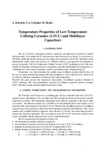
The crystalline phases of commercially available tapes offered by Du Pont (DP 951), Ferro (two modifications of A6-M system) and Heraeus (CT 700) have been investigated. The as-manufactured, dried and fired tapes have been tested. The influence of thermal history of various tapes on their phase constitution is shown in Fig. 1. Table 1. Low Temperature Cofired Ceramics subjected to X-ray analysis Trade mark and colour
Producer
DP 951 (blue) A6-M (brown) A6-M (white) CT 700 (dark blue)
Du Pont Ferro Ferro Heraeus
Marks used in figures “green tape”
Dried tapes
Fired tapes
D-0 F1-0 F2-0 H-0
D-450
D-875 F1-850 F2-850 H-850
H-350
100
50
D- 0 D - 450 D - 875
[a.u.]
60
40
20
30
20
10
0
0 10
H- 0 H - 350 H - 850
40
Intensity
Intensity [a.u.]
80
20
30
40
50
60
70
80
90
100
10
110
20
30
40
50
70
70
80
90
100
110
60
F1 - 0 F1 - 850
60
F1 - 850 F2 - 850
50
[a.u.]
50
[a.u.]
60
2
2
40
40
Intensity
Intensity
30 30 20 10
10 0
0 10
20
20
30
40
50
60
70
80
90
100
10
110
2
20
30
40
50
60
70
80
90
100
110
2
Fig. 1. Influence of thermal treatment on the phase constitution of low temperature ceramic tapes from various manufacturers
These results confirm significant differentiation of chemical composition and crystalline constitution of low temperature ceramic tapes [4-6]. However our investigations disclosed new crystalline phases both in green tapes as well as complete fired ones. Al2O 3 with corundum structure is the only crystalline phase in DP 951 2
Proc. 24 th IMAPS-Poland Chapter Conf., Rytro (Poland), p.163-168
tape. Because its intensity does not change during subsequent thermal processes therefore this system can be treated as unreactive. Green CT 700 tape is based on Al8B2O15. However additional crystalline phase – hexagonal BaAl2Si2O8 – is created and the contents of both crystalline phases is comparable after firing at 850oC. Amorphous or small-crystalline wollastinite (CaSiO 3) is visible in green A6-M tapes. Temperature treatment leads to precipitation and crystallization of much larger amount of these crystallites. 3. Thermal and thermogravimetric investigations of LTCC Thermal (DTA) and thermogravimetric (TG, DTG) analyses have been made in air in the range from 25 to 1000oC under 5 oC/min heating range. Examples of TG, DTG and DTA curves are shown in Fig. 2 whereas the remaining results are given in Table 2. The total weight loss corresponds to a content of organic vehicle. This is equal to 18 wt. % for Ferro tapes, 11% for Du Pont and 8% for Heraeus ones. Therefore it is not strange that Ferro recommends much longer drying stage than the other tape producers. Mentioned weight loss is observed in two temperature sub-ranges. This testifies to application of two-component organic vehicles by all manufacturers. There are no further thermal effects after removing of organic components in DP 951 tapes. The shape of DTA curve above 400oC is characteristic for transformation range of glass phase [7]. However additional, small exothermic effects are characteristic for Ferro and Heraeus tapes at temperatures of about 800850oC. One should suppose that they are connected with changes in crystalline structure reported in Chapter 2. Based on results presented in previous and this chapter we can tell that drying process causes only total burnout of organic part of green tapes but does not affect further sintering process. 0
0
TG
TG
-5
DTA
DTA
-5 DTG
DTG
o
-10
m/m [%]
m/m [%]
-10 o
-15
-20
-25
-15
-20
A6-M from Ferro
-25
-30
DP 951 from Du Pont
-30 200
400
600
800
200
Temperature [°C]
400
600
800
Temperature [°C]
Fig. 2. Thermogravimetric curve (TG), its derivative (DTG) as well as differential thermal analysis for Ferro (A6-M) and Du Pont (DP 951) ceramic tapes
3
Proc. 24 th IMAPS-Poland Chapter Conf., Rytro (Poland), p.163-168
Table 2. Results of DTA and DTG for Low Temperature Cofired Ceramics Number 1
Mark CT 700 (Heraeus)
Temperature range [oC] 162-551 351-487
2
3 4
DTGmin [oC]
DTApeak [oC]
233 (bending) 280 411
246 (bending) 329 414 868 (bending) 755 785 931
Ferro (brown), dried DP 951, dried CT 700, dried
429 852-874 (bending)
Weight decrease [wt %] 6.18 1.73 ( =7.91) - ( =0) ( =0) 0.57 - ( =0.57)
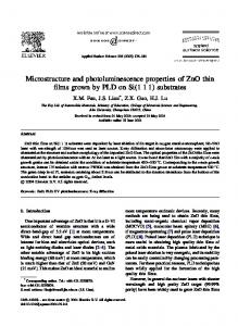
4. Morphology of buried LTCC components Observations in SEM and EDS analyses have been performed with a Jeol JSM-5800 LV microscope equipped with Oxford EDAX system. Laser cutting has been used for cross-sections fabrication of buried LTCC structures and components [8]. The microscope observations both in COMPO (material contrast) and TOPO (topographical contrast i.e. image detected by backscattered electrons) modes together with charts of particular elements distribution have been made for every analysed samples. The cross-section of DP 2051 resistor (100 k ) buried inside DP 951 LTCC structure is shown in Fig. 3 as an example. Many spherical bubbles with diameter below 1 m and single ones with diameter of about 5 m are visible in buried resistors. Low temperature ceramics is much more compact. Clear border between resistors and ceramics indicates small depth of interface region between LTCC substrate and thickfilm resistor. Much finer crystalline grains are present in resistive film in comparison with ceramic tape. Comparable concentration of Ca and Si exists in DP 951 tape and DP 2051 resistor. However the amount of lead is much larger inside resistive film than in ceramic tape. 5. Conclusions Commercially available cermet thick-film materials are compatible with alumina substrate. However, compositions of glass-ceramic tapes, which are the key part of LTCC materials systems differ considerably not only from standard 96% Al2O3 substrate but also among products offered by every leading manufacturers of thick-film electronic materials. The investigations presented above show significant difference in basic materials and tape behaviour during high-temperature process. The DP 951 tape based on unreactive corundum crystalline phase and lead-silica glass is nearest to standard alumina. Phase composition of A6-M and CT 700 tapes is changed in dynamic – it is dependent on firing stage. Therefore it is more difficult to work out compatible conductive and resistive systems to them [9]. However they are composed of much less Pb. Therefore Du Pont products probably will undergo much larger changes in the nearest future than Heraeus and Ferro LTCC systems.
4
Proc. 24 th IMAPS-Poland Chapter Conf., Rytro (Poland), p.163-168
Topo
Compo
Ru
Pb
Ca
Si
Fig. 3. SEM images and charts of elements distribution for DP 2051 resistor buried in DP 951 tape
5
Proc. 24 th IMAPS-Poland Chapter Conf., Rytro (Poland), p.163-168
Acknowledgment The authors would like to thank Dr. Ewa Ingier-Stocka for thermal and thermograwimetric measurements. References 1. A. Dziedzic; Non-standard physicochemical and electrical examinations in thick -film and LTCC technologies, Proc. 22nd Int. Conf. on Microelectronics (MIEL 2000), Niš (Yugoslavia), May 2000, p.497-504 2. R.C. Sutterlin, G.O. Dayton, J.V. Biggers; Thick-film resistor/dielectric interactions in a Low Temperature Co-fired Ceramic Package, IEEE Trans. on Components, Packaging, and Manufacturing Technology – Part B, vol.18 (1995), p.346-351 3. ASTM Powder Diffraction Files 4. R.R. Tummala; Ceramic and glass-ceramic packaging in the 1990s, J. American Ceramic Soc., vol.74 (1991), p.895 5. A.A. Shapiro, D.F. Elwall, P. Imamura, M.L. McCartney; Structure-property relationships in Low Temperature Cofired Ceramic, Proc. 1994 Int. Microelectronics Symp. (ISHM-USA), 1994, p.306-311 6. D. Szwagierczak; Ceramika o niskiej stałej dielektrycznej na podłoża dla elektroniki, Szkło i Ceramika, vol.48 (1997), s.25-29 7. M. Prudenziati, B. Morten, P. Savigni, G. Guizetti; Influence of the preparing conditions on the physicochemical characteristics of glasses for thick film hybrid microelectronics, J. Mater. Res., vol.9 (1994), p.2304-2313 8. J. Kita, A. Dziedzic, L.J. Golonka; Non-conventional application of laser in LTCC and thick-film technology – preliminary results, Proc. 23rd Int. Spring Seminar on Electronics Technology (ISSE 2000), Balatonfured (Hungary), May 2000, p.219-224 9. A. Dziedzic, L.J. Golonka, M. Henke, J. Kita, H. Thust, K.-H. Drue, R. Bauer, L. Rebenklau, K.-J. Wolter, Electrical and structural characterization of thick-film resistors at various LTCC systems, Proc. 1999 Int. Microelectronics Symp. (IMAPS-USA), 1999, p.510-515
6