MATEC Web of Conferences 161, 02010 (2018) https://doi.org/10.1051/matecconf/201816102010 13th International Scientific-Technical Conference on Electromechanics and Robotics “Zavalishin’s Readings” - 2018
Maintenance problems of PWM-inverters in power networks with distributed generation Pavel Kuznetsov1, *, Sergej Solyonyj2, Yuriy Sychev 1 and Boris Abramovich1 1
Saint-Petersburg Mining University, Department of Power Industry and Electromechanics, 199106, Saint Petersburg, Russia Saint-Petersburg State University of Aerospace Instrumentation, Department of Electromechanics and robotics, 190000 Saint Petersburg, Russia 2
Abstract. This article observes maintenance problems of PWM-Electric Drive in Power Networks with distributed generation (DG). Compared to conventional centralized networks harmonics disturbances and non-sinusoidal waveforms happen faster in DG networks due to bigger amount of non-linear loads (Frequency and Power AC and DC Converters, PWM-Electric Drive, etc.). As a result, general stability, power quality and uninterruptible power supply can be disturbed. In order to prevent these factors a complex of power conditioning measures is proposed in this article. It demonstrates the possible influence of Active Power Filters with selective harmonics compensation function implementation together with developed controller and preventive algorithm. Almost all modelling was performed in Matlab/Simulink software.
1 Introduction Recent statistics analysis demonstrates that power supply networks with DG are being implemented and created fast [1,2]. This happens due to some obvious benefits that DG networks have compare to conventional centralized grids: • convenient location near end user; • lower costs for energy transmission due to shorter distribution lines or their complete absence [3]; • excellent possibility to use low and mid power generators of renewable energy [4]; • integration of microturbines and creation of islanded electromechanical complexes; • energy consumption from main network during peak odes and energy transfer into main network during standstill periods [5]. However, during real operation of DG networks many disturbances happen that lead to power quality worsening, emergency modes, and possible total blackouts [6]. One of these disturbances are current and voltage harmonics, which are injected into the grid by non-linear loads. In addition, they are closely connected with reactive power that implies the power factor and leads to overheating of power electronics, electromecanical equipment and total network overload.
2 Analysis of existing solutions Classical reactive power compensation theory was very popular and widely implemented in conventional centralized power grids. Its idea is based on the fact when inductive or capacitive reactive power is compensated by *
opposite reactive element. For example, if industrial enterprise (petroleum or refinery plant) has a lot of induction motors, which produce inductive current and inductive reactive power it was enough to install capacitive batteries that would compensate this dangerous currents and correct total network’s power factor. However, situation changed with the fast development of semiconductor electronics. Integration of frequency converters, household power electronics, invertors and DG led to the change of the reactive power and harmonics nature, where convenient reactive power compensation theory was unsuitable. This happened due to the reason when passive reactive compensating elements can lead to resonances, overheating and even explosion trying to compensate reactive currents from non-linear loads. That is why new power conditioners were invented recently. The most perspective invention are Active Power Filters (APFs) that were created using Instantaneous Power Theory [7]. This article observes and describes protective complex of power conditioners that for implementation in islanded DG power networks on the example of petroleum plant. It also proposes protective algorithm against occurrence of emergency modes. Last part of the article demonstrates modelling results of protective algorithm in Matlab-Simulink libraries and proposed prototype of protective controller.
3 Protective algorithm for DG networks DG power networks are considered to be more robust and efficient compare to conventional centralized power grids. This happens due to their more flexible structure
Corresponding author:
[email protected]
© The Authors, published by EDP Sciences. This is an open access article distributed under the terms of the Creative Commons Attribution License 4.0 (http://creativecommons.org/licenses/by/4.0/).
MATEC Web of Conferences 161, 02010 (2018) https://doi.org/10.1051/matecconf/201816102010 13th International Scientific-Technical Conference on Electromechanics and Robotics “Zavalishin’s Readings” - 2018
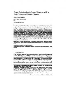
and presence of bigger generators’ amount. As a result, emergency modes consequences can vary and differ from their analogues in centralized grids (for example sudden power loss due to wave form worsening because of harmonics presence). This also has to be considered during their severity analysis. In order to make it complex and correct there was developed a modernized algorithm, first proposed in [8] where development of cascade outages was corrected according to DG power networks. It is shown on Figure 1.
the power source at the high frequency. Since the harmonics exist in the current drawn, the source is treated as a current source. Unlike the voltage source, the ideal current source has infinity internal impedance and prefers zero load impedance to maintain the current. The nonlinear load can be represented as linear load part and the high frequency current sources. For simplicity consider the situation where the only one of the connected loads is nonlinear and is produces only 5th order harmonic current. This scheme is shown on Figure 2.
Fig. 2. Ideal current source scheme.
The 5th harmonic current is produced by the current source which is part of the load operation, and is fed to the network through the junction A. From the junction A the current will choose the lowest impedance path to flow. The left side impedance is the internal impedance of the distribution transformer in additional to the line impedance. The total impedance of the left side is very much lower than the fully loaded right side. Figure 3 shows how most of the harmonic current will flow towards the power transformer.
Fig. 1. Modernized algorithm of cascade outage’s development in power network with DG.
As it was established during algorithm development DG power networks are more robust and can stand emergency modes and cascade outages. Even more so, after cascade outages total blackout has a low possibility to happen because power network will be split up to several islanded regions. However, the main problem is hidden in their future synchronization in one stable grid. In addition, presence of PWM-converters, electric dive, inverters, etc. leads to worsening of power quality and grid’s destabilization. Next chapter studies possible solutions to minimize this influence.
Fig. 3. Scheme of harmonic source that operates as a current source connected across the load.
Following the line and internal transformer impedances, the harmonic current creates the high frequency voltage drop. This is how voltage harmonics are created. In addition, the current, which passes through transformer secondary, will create the harmonics on the primary transformer side as well. Now assume that power factor correction is required due to a low power factor at the fundamental frequency. Power factor correction capacitors are added to correct the power factor. Figure 4 reveals this situation.
4 Harmonics and existing protective devices Non-linear loads create harmonics, and initially they are current waves. The spectrum frequencies (harmonic order) and the magnitudes of those current waves depend only on the nature of the load. For example, most DC drives have 6-pulse rectifiers, which generate mostly 5th and 7th order harmonics. The 5th harmonic has a frequency five times the fundamental and the 7th is seven times the fundamental. The harmonic is actually
Fig. 4. PFC capacitors can create a resonant circuit at harmonic frequencies.
2
MATEC Web of Conferences 161, 02010 (2018) https://doi.org/10.1051/matecconf/201816102010 13th International Scientific-Technical Conference on Electromechanics and Robotics “Zavalishin’s Readings” - 2018
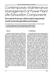
The harmonic current coming to the junction B will encounter the capacitor and connected in parallel to it resistance and reactance. The resistance part is negligible in most cases, so the above can be represented as parallel resonance circuit in the path of the 5th harmonic current. The case where Xl will be equal to Xc and parallel resonance will take place is shown on Figure 5.
In the recent time, different types of APFs have obtained a huge support in conventional power networks due to their increased performance and harmonics compensation. Some of these devices were proposed in [10-12]. Figure 7 demonstrates possible implementation of APF in power network with nonlinear load. These units have significant benefits: reduced switching-voltage ratings, smaller switching stresses dv/dt and an improved output voltage at lower switching frequencies. These characteristics have led to the development of many applications.
Fig. 5. Resonant circuit scheme at 5th harmonic.
Parallel resonance raises the circuit impedance. Current circulates between the capacitor and the inductance without being passed to the grounded terminal. In the case of parallel resonance or even close to resonance condition, the path, which includes distributing transformer and PF capacitors have a very high impedance at the harmonic current frequency. At parallel resonance condition the harmonic current is forced to go to the load. Since the path impedance is increased, the voltage harmonic is increased as well too. This situation may cause a significant damage to the electrical infrastructure. Normally, the weakest part, which fails first in such a condition, is the PF capacitor. The PF capacitor most likely cannot withstand the high harmonic current, which is circulating between the capacitors and the distribution transformer [9]. The parallel resonance frequency always exists in cases where the capacitors are used for PF correction. The way to prevent parallel resonance occurring is to insure that the frequency of resonance is located outside the harmonic range. This is the main idea behind the “detuned” system configuration (see Figure 6). The 7% or 5,67% inductors move the resonance point below the 4th harmonic which insures safe operation for the three phase delta capacitors in cases where the third harmonic is balanced.
Fig. 7. APF’s integration scheme in the DG power network.
The presented APF’s modification can compensate harmonics selectively. This feature plays an important role in DG power networks because of different nonlinear load types. Inverters, converters, electric dive, lighting, etc. produce different harmonics types in different amounts. Last researches [11,13-14] demonstrate that according to IEEE 1592-2013 requirements only two-three main harmonics bring 80% of disturbances. APF allow to compensate only them, not exceeding limited DG network’s power limit. During normal operation, generators and other electromecanical equipment create parasitical oscillations that can destabilize their stable rotational speed. Taking into account harmonics from non-linear loads in DG power networks a hazardous situation can occur when rotational mechanical oscillation summarize with harmonics distortion. In order to prevent this APFs are used together with Power system Stabilizers (PSS).
5 Modelling and discussion In order to show positive effect of APFs application and demonstrate their positive effects in DG networks modelling was provided in Matlab-Simulink software. Model developed in [15] was used as the main DG power network. Its part is shown on Figure 8. Power network consists of 39 buses, 19 loads, and 10 generators with generator one, connected to bus 39. Generally, model has the following possibilities in order to research DG power networks properties: • Three-phase PI section line blocks are used to represent transmission lines. Positive- and zerosequence resistances, inductances, capacitances, and line length can be set. • All loads are represented by three-phase parallel RLC load in PQ type (Y-grounded configuration) since
Fig. 6. Resonant circuit at 5th harmonic.
3
MATEC Web of Conferences 161, 02010 (2018) https://doi.org/10.1051/matecconf/201816102010 13th International Scientific-Technical Conference on Electromechanics and Robotics “Zavalishin’s Readings” - 2018
corresponding references provided load data in active and reactive demands. Different types of connection configuration and types are available.
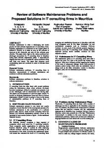
Second part of the modeling consisted in connecting APF fore 5th and 7th harmonics compensation together with PSS for stability improvement during emergency mode. Simulation plots are shown on Figure 10.
Fig. 8. Part of the test model in Matlab-Simulink.
• Three-phase transformer block are used to model all the transformers of the test systems. Y-Y connection for interconnecting transformer and Δ-Yg connection for generator transformer can be set. • Generators are modelled by three-phase synchronous machine in dq rotor reference frame while d-axis and qaxis time constants vary to best fit with given data. • If applied, single mass tandem compound steam prime mover including speed regulator, steam turbine and a shaft is set to model steam turbine and governor. • Each generator equipped with three types of Power System Stabilizers (PSSs), Multi-Band PSS (MBPSS), Delta omega generic PSS, and Delta Pa generic PSS. Non-linear loads with harmonics sources were added to the system in order to improve it functionality for power quality research. A simulation was done when a cascade outage starts close to bus 15 due to loss of synchronism because of harmonics presence. Also, a 3-pahse shortcircuit occur at a time 2 s and lasts for 4 seconds. First simulation (Figure 9) shows that without PSS and APF all generators loose synchronism after 6 seconds and cascade outage completely destroys system, leaving even no operating islanded parts.
Fig. 10. Results of PSS and APF implementation.
Protective devices successfully overrode the same emergency mode. Bus voltages have completely recovered and got rid from pulsations after 7 seconds and generators’ angular speed was restored after 13.5 seconds. This proves effectiveness of the proposed protective measures.
6 Conclusion The research was conducted in order to demonstrate key benefits and incompleteness of power networks with DG. The developed protective algorithm that demonstrated development of cascade outage it DG power network can be used an implemented in real power networks in order to increase their stability. Conducted research revealed that harmonics from non-linear loads can damage operating equipment and destabilize DG grid. APFs were proposed to be used in order to compensate disturbances selectively. Simulation of DG power network with APF demonstrated improved grid’s stability and increased robustness. Simulation results and algorithm proposed to be realized in protective controller against cascade outages. The presented results were obtained as a part of scientific research according to the contract №11036GU/2016 “The development of power network condition controller with blackout prevention possibility” provided by Foundation for Assistance to Small Innovative Enterprises in Science and Technology (FASIE). The presented results were obtained as a part of scientific researches according to the contract № 13.3746.2017.8.9 “The designing on the basis of systematic and logic probability evaluations of rational and economically proved structure of centralized, autonomous and combined power supply systems with high reliability and stability level with usage of alternative
Fig. 9. Destruction of the system during cascade outage due to harmonics presence.
4
MATEC Web of Conferences 161, 02010 (2018) https://doi.org/10.1051/matecconf/201816102010 13th International Scientific-Technical Conference on Electromechanics and Robotics “Zavalishin’s Readings” - 2018 and renewable power sources for uninterrupted power supply of enterprises with continuous technological cycle”.
References 1. 2. 3. 4. 5. 6. 7. 8. 9. 10.
11. 12. 13. 14. 15.
H. Martinez-Garcia, Jornades de Recerca EUETIB 2014, 12, 100–109 (2014) J.O. Rezende, L.M. Peres, G.C. Guimarães, A.J. de Moraes, M.A. Tamashiro, Renewable Energy and Quality Journal (RE&PQJ), 12 (2014) A. Arjun M, B.K Uma Rao, C.A B Raju, Renewable Energy and Quality Journal (RE&PQJ), 12, (2014) B.N. Abramovich, Y.А. Sychev, International Journal of Applied Engineering Research, 11 (4), 2640–2645 (2016) B.N. Abramovich, Yu.A. Sychev, A.S. Mingazov, V.V. Polishuk, 10, 126–127 (2013) P.A. Kuznetsov, O.A. Stepanov, Aerospace MAI Journal, 4, 157–163 (2017) H. Akagi, E.H. Watanabe, M. Aredes, Instantaneous power theory and applications for power conditioning (IEEE Press, 2007) P. Pourbeik, P. Kundur, C. Taylor, IEEE Power and Energy Magazine 4(5), 22–29 (2006) G. Whittle, Energize, 11 (2010) V. Khadkikar, M. Singh, A. Chandra, B. Singh, 2010 Joint International Conference on Power Electronics, Drives and Energy Systems (PEDES) & 2010 Power India, 1 (2010) M.B. Said-Romdhane, M.W. Naouar, I.S. Belkhodja, E. Monmasson, Energies, 10, 1–19, (2017) J.L. Monroy-Morales, D. Campos-Gaona, M. Hernandez-Angeles, R. Pena-Alzola, J.L. Guardado-Zavala, Energies, 10, 1–23, (2017) S. Golestan, M. Monfared, J. Guerrero, Power Electronics, Drive Systems and Technologies Conference (PEDSTC), 2013 4th, 510–517 (2013) Yu. Huang, P.M. Pardalos, Q.P. Zheng, Electrical Power Unit Commitment (Springer, 2017) A. Moeini1, I. Kamwa, P. Brunelle, G. Sybille, IEEE Power Engineering Conference (UPEC), 1–19, (2015)
5