850 rue Jean Monnet, 38926 Crolles, France. {Pascal.Urard}@st.com ..... [7] G. H. Büttner, âSetting up a retrieval system for design reuseâExperiences and ...
Matlab based Environment for designing DSP Systems using IP blocks N. Zergainoh, K. Popovici, A.A. Jerraya, P. Urard† TIMA Laboratory 46 av. Felix Viallet 38031 Grenoble France {Nacer-Eddine.Zergainoh, Katalin.Popovici, Ahmed.Jerraya}@imag.fr † ST Microelectronics 850 rue Jean Monnet, 38926 Crolles, France {Pascal.Urard}@st.com
Abstract – In this paper, we propose an efficient IP block based design environment for high throughput VLSI Systems. The flow generates SystemC Register Transfer Level (RTL) architecture, starting from a Matlab functional model described as a netlist of functional IP. The refinement model inserts automatically control structures to manage delays induced by the use of RTL IPs. It also inserts a control structure to coordinate the execution of parallel clocked IP. The delays may be managed by registers or by counters included in the control structure. The experimentations show that the approach can produce efficient RTL architecture and allow for huge saving of time.
I Introduction As the complexity of the high-throughput dedicated digital signal processing (DSP) systems increase, development efforts increase dramatically. At the same time, the market dynamics for electronic systems push for shorter development times [1]. In order to meet the design time requirements, a design methodology for VLSI dedicated DSP system that favors reuse and early error detection is essential. One idea, largely widespread and applied to design DSP systems, is to adopt a modular approach based on recursive use of the divide-and-conquer strategy [20]. The global complexity of the system should be broken down into subsystems (i.e. elementary signal processing functions), well known and of easily accessible complexity such as filter (FIR, IIR), fast Fourier transform (FFT), Viterbi decoder, etc. The system can be obtained by the hierarchical assembly of these common functions of signal processing (also known as IP blocks). The intellectual property (IP)-based design is obviously an important issue for improving not only design productivity, but also design from the higher-level abstraction. However, there are two major problems that designers encounter with the IP block-based design approach. The first problem (Problem 1) is the difficulty in using IPs blocks for high-throughput DSP systems that require various performances (throughput) or functions with non-standard algorithms. This is because VLSI DSP system cannot be parameterized for global performance and functions; for example, necessary processing cycles cannot be adjusted for IPs blocks. The second problem (Problem 2) comes from interfacing of IPs blocks between them [19]. Designers have to design IPs blocks that can communicate according to the
blocks’ interface specification. When they connect two different IP blocks, they have to insert an extra interface circuitry in order to synchronize them. Area and delay overhead for circuitry cannot be neglected in some cases. A lot of research has been carried out on the IP-based design [2], [3], [4], [5], [6], [7], [8], [9], [10], [11], [12], [13]. Most of the research deals with IP-based SoC [10]-[13]. Problems on SoC synthesis are addressed in [21], where it is assumed that an external reference clock is supplied and the asynchronous communication is used. However, most of on-chip buses for SoC use the synchronous communication. IP blocks are also exploited in the application-specific instruction set processor (ASIP) synthesis for the embedded DSP software [3]. To accelerate the execution of the software, they select an optimal set of IPs and interface types for each IP. However, the interface types for IPs are restricted to coprocessor integration style. Interrupt/trap or shared-mapped IO memories are often used. The software called handshaking offers flexible communication between hardware and software, but it is too slow. Some researchers are trying to develop general communication interfaces in hardware. In the area of the application-specific integrated circuit (ASIC) design, communication between IP’s is often conducted by shared registers or shared memories. The typical interface configuration contains multiplexers with enable signals or address decoders. The concept of a generic virtual interface has been attracting a lot of attention as a way to increase the design reuse. General virtual interfaces lead to designers believing that any IP could communicate with any other IP [24]. Some practical approaches are reported such as the automatic matching/generation/deletion of interface pins [24], [26], [27]. General virtual interfaces are kinds of wrapper IPs, so they would have the area and delay overhead. In regards circuit design, the asynchronous circuit interface has attracted some attention from designers as a general IP interface. This is because it has been suggested that asynchronous communication might result in more general and faster handshaking than synchronous handshaking communication. Since this interface enables arbitrary communication between IPs in different clock-frequency domains, the local clock frequency of each IP block could be much faster than the global clock that is determined by the slowest IP.
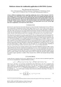
Functional Model Generic Functional DSP-IP Library
OUT
IN F-IP1
F-IP2
F-IP3
System-level Simulation (Parameters Exploration)
F-IP4
Refinement (Parameters Extraction, FSM
Automatic Delay Correction Method
Integration, Automatic Assembly)
RTL Architecture FSM
Generic RTL DSP-IP Library
OUT
IN RTL-IP1
RTL-IP2
RTL-IP3
Behavior Difference?
RTL-IP4
Fig. 1. IP-based design methodology for VLSI Dedicated DSP In this paper, we propose an efficient IP block based design environment for high throughput VLSI dedicated Digital Signal Processing (DSP) Systems called DSP Macro-cells Builder Tool. The flow generates SystemC Register Transfer Level (RTL) architecture, starting from a Matlab functional model described as a netlist of functional IP. The refinement model inserts automatically control structures to manage delays induced by the use of RTL IPs. It also inserts a control structure to coordinate the execution of parallel clocked IP. The delays may be managed by registers or by counters included in the control structure. The global approach is based on design practices that were already described in [17], [18]. The main contribution of this paper is a prototype implementation and experimentation of the approach. The rest of the paper is organized as follows. Next section presents an overview of the methodology and design flow. Section III details the IP block-based design environment for high throughput VLSI DSP Systems. Section IV presents several experiments to analyze the efficiency of the proposed design flow. Finally, section V gives our conclusion on the work presented in this paper.
values (i.e. architectural parameters values such as bit width) is made by the system designer in order to satisfy a trade-off between signal quality and implementation constraints. To generate the architecture, IP parameter values are firstly extracted from a validated functional architecture model and then used to instantiate the pre-designed RTL IP written in synthesizable hardware language (i.e. VHDL, SystemC). The architecture is then built by automatic assembly of pre-designed RTL IPs (with the same assembly topology as the functional model). The design flow includes a unified verification platform used to verify both RTL and functional model. The platform exploits directly the high-level environment used for functional validation. The results of the methodology are a safety functional and RTL models of the whole DSP application. The functional model can be used such as an executable reference for the next generation of design. Overall, the final architecture takes implicit advantage of the hardware designer expertise. The RTL model is suitable for logical synthesis.
II. Overview of Design Methodology
To provide IPs with more reusability and flexibility (problem 1) we are developing parameterized reusable DSP components at functional and RTL called respectively “generic F-IP and generic RTL-IP. We define the generic F-IP as template described in Matlab hybrid representation [23], [17], [18]; many details are left open, only some signals which are relevant for the quantification are implemented in quantified integer. The generic F-IP blocks are stored in library. We define the generic RTL-IP as a synthesizable RTL model of a basic DSP block. Each F-IP is mapped on one or more RTL-IP. A typical RTL-IP is shown in Fig. 2 (where the generic parameters are in italic). The external interface concepts (e.g. external ports-structure, functional, and timing details, generic parameters …) of IPs provide how the IP block exchanges information with its environment. The F-IP interface defines the component name, I/O data-stream names,
The IP-based design methodology is based on designer’s practice [17], [18]. The methodology, depicted in Fig. 1, generates register transfer level (RTL) architecture, starting from a functional model given in Matlab. The functional modeling and RTL architecture generation are performed using two libraries of pre-designed DSP basic blocks (i.e. functional and RTL libraries). In our IP block-based design approach, the functional model is created through assembly of existing functional IP written in Matlab [23]. The refinement process keeps the same architecture and replaces each functional IP by a corresponding RTL one according to a set of parameters given by the designer. These are present as attributes in the functional model. The choice of IP parameter
A. Generic DSP-IPs blocks
N = number of coefficients nbit_in 1
IN
1
Z-
coeff_1
1
Z-
Z-
coeff_2
coeff_N
nbit_sum Round
Saturation
OUT
Fig. 2. Generic RTL-IP description of FIR filter and generic parameters names. The external interface information of RTL-IP block is described by the component definition (including component name, generic parameters names, ports names, ports directions, and ports data types). The ports can be data, clock, reset, control and test ports. Fig. 3 illustrates the analogy between F-IP and RTL-IP interfaces. Therefore, just by setting appropriate parameters, unnecessary functions and redundant interfaces are eliminated in the IP-based assembly approach (no need to insert an extra interface circuitry). Furthermore, the designer does not have to pay attention to the communication of interface protocols. B. Overview of Delay Correction Method Although each functional IP and its equivalent RTL produce the same digital displays, in some cases, the register transfer model obtained by automatic assembly from the functional model can be wrong [18]. This can occur due to delays induced by implementation constraints (pipeline registers, output buffers, etc.). This behavioral fault is caused by the existence of delays on the RTL model which cannot be found on the functional model. These delays occur when the DSP application contains: parallel branches of IPs converging toward another IP, feedback loops of IPs, and/or time-varying IP. This problem is generally known as retiming issue. There are three main techniques able to correct the different behavior between the two models. The first technique involves the insertion of synchronization protocol (e.g. handshake protocol) on each component IP which indicates when the input and output data are valid. The advantage of this technique is that the delay problems are solved before the Functional
in1
in2
Generic F-IP block para1, para2
out1
out2
Component GRT_IP generic ( param1: positive; param2: positive);
RTL in1 in2
Generic RTL-IP block
En#1 En#2 Clock Reset Legend:
para1, para2
Systematic Analogy
Function [out1, out2] = GF_IP ( in1, in2, param1, param2)
out1
port ( in1: IN std_...; in2: IN std_...; out1: OUT std_...; out2: OUT std_...;
Outputs Inputs Generic Parameters
Generic parameters
Inputs Outputs
control: IN std_...; clock: IN std_...; Other ports reset: IN std_...) end component;
Fig. 3. F-IP interface versus RTL-IP interface
assembly of RTL IPs. The main drawback to this technique is the area and delay overhead in each IP. However, the problem only occurs in the above three cases. The second technique involves the insertion of registers between RTL IPs in order to compensate for additive delays. This technique has the advantage of being non-intrusive. However, performing the corrections manually (i.e. locating the places where there are problems, determining exactly how many registers need to be inserted and where to insert them) is a very difficult task with increase in the number of IPs. The third technique involves the modification of the initial Finite State Machine (FSM) by generating additional signals to control the IPs. These signals are time shifted of the initial signals of the global FSM. They are therefore able to put-back or to put-forward the activation of the IPs. This technique adopts various stages of the second technique (i.e. locating the places where there are problems, determining exactly how many signals are needed) and requires the FSM to be modified. Modification costs increase with the complexity of the FSM (multiplication of the number of control signals and increases in the number of states). In our IP block-based design, we have implemented a systematic approach called “Automatic Delay Correction Method (ADCM) to solve the problem without inserting an extra interface circuitry. The ADCM implements efficiently the two above techniques (register-insertion-based and FSM modification-based).
III. DSP Macrocell Builder: IP block-based design environment for high throughput VLSI Dedicated DSP Our IP block-based design environment called “DSP Macrocell builder” shown in Fig. 4 consists of system-level validation flow, hardware design flow (including datapath and FSM), and delay correction flow for high throughput VLSI Dedicated DSP systems. The main feature of our configuration is that the tool flow is based on a unified design model for simulation and synthesis of System-on-Chip (SoC) architectures, called “Colif” [14]-[16]. Other tools take advantage of information from the Colif and the characteristics of the generic IPs libraries. Initially, a designer uses the generic F-IP library to describe his functional model on Matlab [23]. He/she explores a pure algorithm for DSP system in Matlab environment [23]. Then, the Mat2Colif tool transforms the matlab description into Colif description. IP parameter values are extracted from a validated functional model and then used Prepare1 and CosimX tools to generate the functional architecture in SystemC [22]. The delay correction flow (including ColifRefiner, ColifLatencer and ADCM), as will be explained later, transforms the Colif functional into a corrected Colif RTL. Architectural parameters are used to instantiate the pre-designed RTL IP written in synthesizable hardware language (i.e. VHDL, SystemC). The DSP Macrocell builder includes the automatic generation of RTL SystemC of the final architecture (including datapath and FSM). After cycle-level simulation, the generated architecture can be passed to a logic synthesis and automatic placement and routing tools, in order to achieve a good performance circuit. The following subsections detail the several automatic phases of the Macrocell builder.
Colif is used as intermediate language for describing the design model through different phases of the DSP Macrocell builder.
Matlab Functional Mat2Colif
.
CosimX COLIF Functional Prepare-1
SystemC functional architecture
ColifRefiner ColifLatencer Delay Correction Method
Registers Insertion-based FSM modification-based (Gendcc, Assembleur, ModFSM)
COLIF RTL
Prepare-2
GenFSM
FSM (SystemC RTL code)
CosimX SystemC RTL Netlist
B. Mat2Colif The Mat2Colif is developed to transform the functional Matlab model into a functional description in COLIF language [16]. It consists of a lexical and syntactical analyzer applied upon the Matlab description, the functions treating the different input parameters of the tool and the functions necessary for produce the correct output file. The tool needs an intermediate variable for integrating the inputs and the outputs. This means that it is not possible to use directly the labels of the inputs and the outputs for calling these functions. After the intermediate form is explored, the tool imports the Colif objects correspondent to functional IPs. After all the objects are correctly imported into the Colif tree structure located in memory, the tool instantiates this structure in order to obtain a suitable file for visualization. This file describes the functional description in COLIF language.
Fig. 4. DSP Macrocell builder
C. ColifRefiner
A. Colif (Co-design Language Independent Format)
The ColifRefiner tool transforms the Colif functional architecture model into Colif RTL model. First, the Colif F-IP’s are substituted for their corresponding Colif RTL-IP’s using the IP’s libraries. Then the module of global FSM is added and the ports-nets connections are performed by this tool. The output result of ColifRefiner is Colif RTL structure description of the system (including datapath and FSM structure). Fig.6 illustrates an example of the input and output of ColifRefiner tool.
Colif is a unified abstract model for high-level system design and refinement methodology [14]-[16]. Colif represents a system as a hierarchical network of virtual components using three basic concepts: module, port and net. Virtual components use wrappers to separate the interface of the internal component from the interface of external nets (see Fig. 5). The wrapper is the set of virtual ports of a virtual component. Virtual ports contain internal and external ports that can be different in terms of communication protocol and abstraction level. Colif use a uniform syntax to represent systems that described at multiple abstraction levels. A virtual port can contain multiple levels of hierarchy to represent an “N: M” (N and M are natural numbers) correspondence between internal and external ports. The internal ports are used to connect the internal behavior of the module to the virtual port. The external ports are used to connect the external communication channel to the virtual port. A virtual channel groups nets that are part of the same communication protocol. Each Colif object has a list of local parameters, e.g. the kind of protocol used in a virtual channel and addresses of ports.
Module Colif: F-IP1 in1
data_in
data_out1
Module Colif: F-IP3
Module Colif: F-IP2 s1
data_in
data_out
s3
data_out data_in2
data_out2 s2
ColifRefiner Module Colif: RTL-IP2
Module Colif: RTL-IP1 in1
data_out1 data_in data_out2 clk nrst enable
Module Colif: RTL-IP3 s1
data_in data_out clk nrst enable
s3
data_in1 data_in2 clk nrst enable
s2
Module Colif: FSM clk nrst
Fig. 5. Colif representation
out1
data_in1
clk
enable
nrst
Fig. 6. Input and Output of ColifRefiner tool
out1 data_out
D. Delay Correction Flow Fig. 7 shows the flow of The Delay Correction Method [18]. The inputs of this flow are both Colif functional and Colif RTL descriptions of the entire system. The output of this flow is a corrected RTL level description producing the same digital displays as functional description. The localization and the calculation of the number of delays to be inserted require the use of an intermediate form called The Differential Graph of Evolution highlighting the delays present in the RTL model and absent from the functional model. For that, the functional model (respectively the RTL model) is represented by a graph called The Functional Graph of Evolution (respectively The RTL Graph of Evolution) describing its own delays. The Differential Graph of Evolution is created by performing the difference between both graphs of evolution (Functional and RTL), i.e., by performing one by one the difference between the weight of edges of the RTL graph and those of the RTL Graph of Evolution. This difference makes it possible to see only the additive delays, due to the constraints of implementation, by removing all the delays related to the functionality. Starting from the differential graph, the ADCM determines the necessary corrections to compensate for the additive delays. The ADCM uses two algorithms to perform the corrections to the differential graph of evolution in order to obtain a balanced graph. The first algorithm determines an optimal solution in latency whereas the second algorithm determines an optimal solution in the number of inserted registers (i.e. optimizing area). Finally, a stage of generation of code produces a corrected RTL description of the system, while inserting the adequate number of delay into the adequate places. The ADCM implements efficiently two alternatives to correct the RTL description of the system: one based on registers insertion while the second is based on FSM modification. According to the implementation constraints and Functional description
the target application, the designer can choose the suitable techniques to be used. In practice, the ColifLatencer tool inserts automatically the latency values into the Colif files (Colif RTL and functional), while The ADCM performs the correction.
IV. Experimental Result In this section we describe the results of an implementation of the ideas presented in this paper towards efficient design and optimization of VLSI Dedicated DSP. In order to highlight the problem of behavior difference and its solution in a real case of IP block-based design, we have willfully selected an example composed of two parallel branches of block IPs tending towards the same IP (see Fig. 8). One contains three FIR filters IPs and the others contain only one FIR filter. A functional and RTL model were built respectively in Matlab [23] and SystemC [22] by assembling the various pre-designed and pre-validated components according to the same assembly topology. A behavior difference between the RTL and functional model has been detected during both functional and cycle accurate simulations (both digital data curves in Fig. 8 are different). The problem is due to an output register present in each RTL FIR filter and absent in functional filters. This register induces an additional delay in the RTL model. The Differential Graph of Evolution is shown in Fig. 9. The first path has three additional delays whereas the second path has one additional delay. It was necessary to add two delays in the second path in order to balance The Differential Graph of Evolution. This delay correction can be translated in two ways on the RTL model. FIR1
FIR2
FIR FIR5
RTL description
FIR4 - - : Matlab : SystemC RTL
Compute the Algorithmic Delay between I/O of the IP
Compute the Delay between I/O of the IP
Functional Graph of Evolution
RTL Graph of Evolution
Delay difference Differential Graph of Evolution
Fig.8. DSP example and problem of behavior difference
IN1
0
FIR1
1
IN2
Fig. 7. Delay Correction Flow
1
FIR3
1
Correction
ADCM
Corrected differential evolution graph
FIR2
0
0
1 +2 FIR4
Fig.9. Balanced differential graph of evolution
FIR5
0
OUT
C1
C1 FIR1
C1
FIR2
C1
C1
FSM
FIR5
C1
C1
-1
-1
FIR4
C1
FIR3
Z
Z
CLK C1
Correction a) Delay correction by registers insertion
C1 FIR1
C1 FIR2
FSM
C1
C1
C1
FIR3
FIR5
C2
C2
CLK C1
FIR4
C2
Correction b) Delay correction by modifying FSM
Fig.10. Two ways to correct the behavior in RTL model The first one involves inserting just two delays in the second path (see Fig. 10-a). The second solution involves modifying the initial FSM at RTL models (see Fig. 10-b). The FSM produces a control signal having a sample period equal to four times the clock period. To correct delays, the FSM must be modified to produce the same control signal, but delayed by two impulses with respect to the initial signal (i.e. 8 clock cycles). Hence, the filter in the second path starts its processing after the same delay as the filters of the first path. Both techniques were applied on this example. Eventually whatever the correction method used, both RTL models produce exactly the same digital values as the functional model as shown in Fig 11. The resulting architectures were synthesized and validated using a Design Compiler [25]. The comparison, in terms of area overhead using AMS technology (0.35 µm2), between both architectures is given in Table 1. As regards the area overheard, both corrections are equivalent and keep the initial frequency. The area overhead of delay correction by registers insertion versus FSM modification may seem significant in some cases. The choice of one of two methods of delay correction will depend on each application.
It is obvious that the automatic delays correction method (including identification of areas where the problems occur, determining how many delays are needed, researching optimal solutions and performing the necessary corrections) decreases significantly the design time overhead. In this experiment, we only compare the time cost of manual FSM modification versus registers insertion from information provided in a corrected Differential Graph of Evolution (i.e. balanced graph). As we noted earlier, only the last step of delay correction was done manually. The correction by registers insertion (~10 min in this example) is much simpler to implement than FSM modification (~45 min). Indeed, the first technique just involves connecting pre-designed blocks delays at the places indicated by The Balanced Differential Graph. The second technique requires the modification of FSM architecture and reconsideration of its states. The FSM modification cost increases with FSM complexity (multiplying the number of control signals increases the number of states). It is necessary that the FSM modification be performed automatically. TABLE 1 Registers insertion-based correction versus FSM modification-based correction Architecture
without correction
Correction by registers insertion
Correction by FSM modification
Area
5415 µm2
5639 µm2
5642 µm2
Max. Clock Freq.
81,3 MHz
81,5 MHz
81,6 MHz
Benchmarks
Fig. 11.
Output signals of functional and corrected RTL models
V. Summary and Conclusions In this paper, we proposed an efficient IP block based design environment for high throughput VLSI Systems. The flow generates SystemC RTL architecture, starting from Matlab-based functional model of digital system. To provide IPs with more reusability and flexibility we are developing parameterized reusable DSP components at functional and RTL called respectively “generic F-IP and generic RTL-IP. Thus, just by setting appropriate parameters, unnecessary functions and redundant interfaces are eliminated in the IP-based design approach. Although each functional IP and its equivalent RTL produce the same digital displays, in some cases, the register transfer model obtained by automatic assembly from the functional model can be wrong. We have also proposed an approach called Automatic Delay Correction Method to solve it without the insertion of an extra interface circuitry. The approach corrects the behavior of the RTL model in a judicious way that includes locating the places where the problems occur, determining how many delays are needed and implementing of the correction. We have described two alternatives (i.e. Registers insertion and FSM modification) to implementing delay correction methods and presented a realistic example where the delay correction method was efficiently applied.
Acknowledgements The authors would like to acknowledge L. Tambour and H. Michel for their input on various topics presented in this paper. They would also like to thank their many colleagues at TIMA and STMicrolectronics for their contribution in definition and implementing the tools.
References [1] International Technology Roadmap for Semiconductors, 2001 Edition Report available http://public.itrs.net [2] G. Martin, “Design methodology for system level IP,” in Proc. Design, Automation and Test in Europe (DATE), 1998, pp. 286–289. [3] H. Choi, et al., “Exploiting intellectual properties in ASIP designs for embedded DSP software,” in Proc. IEEE/ACM Design Automation Conf. (DAC), 1999, pp. 939–944. [4] B.W Kim, C.M. Kyung, “Exploiting IPs with Imprecise Design Costs for System-on-Chip Synthesis,” in IEEE Transactions on VLSI, vol. 10, June, 2002. [6] Lee E.A., Xiong Y., “System-level types for component-based design” Technical report, UCB/ERL M00/8, University of California, Berkeley, 2000. [7] G. H. Büttner, “Setting up a retrieval system for design reuse—Experiences and acceptance,” in Proc. Design, Automation and Test in Europe (DATE), 1995, pp. 575–578. [8] N. Faulhaber and R. Seepold, “A flexible classification model for reuse of virtual components,” in Reuse Techniques for VLSI Design. Norwell, MA, Kluwer, 1999. [9] D. Gajski, R. Dömer, J. Zhu, "IP-centric Methodology and Specification Language," in Distributed and Parallel Embedded Systems, Kluwer Academic Publishers, Boston,
MA, ISBN 0-7923-8614-0, September 1999. [10] R. K. Gupta and Y. Zorian. “Introducing Core-Based System Design”, IEEE Design and Test of Computers, Vol. 13, No 4, October-December 1997, pp. 15-25. [11] M. Keating and P. Bricaud, “Reuse Methodology Manual for System-On-A-Chip Designs”, Kluwer Academic Publishers, 1998. [12] N. Zergainoh, et al. “Framework for System Design, Validation and Fast Prototyping of Multiprocessor SoCs", chapter in "Architecture and Design of Distributed Embedded Systems", Edited by B. Kleinjohann, Kluwer Academic Publishers, April 2001. [13] W. Cesario, et al., ”Component-Based Design Approach for Multicore SoCs ", DAC'02, June 10-14 2002, New Orleans, USA, 2002. [14] W. Cesario, et al., "Object-based Hardware/Software Component Interconnection Model for Interface Design in System-on-a-chip Circuits", The Journal of Systems and Software, Vol. 70/3 pp. 229-244, Elsevier Science, 2003. [15] W. Cesario, et al., "Colif: a Multilevel Design Representation for Application-Specific Multiprocessor System-on-Chip Design", 12th IEEE International Workshop on Rapid System Prototyping, California, USA, June 2001. [16] W. Cesario, et al., "Colif: A Design Representation for Application-Specific Multiprocessor SOCs", IEEE Design & Test of Computers, Vol. 18 n° 5, Sept/Oct 2001. [17] L. Tambour, et al., “Efficient Methodology and Semi-automated Flow for Design and Validation of Complex DSP ASIC Macro-Cells.”, 14th IEEE RSP, 2003. [18] L. Tambour, “Methodologie et flot semi-automatique d’aide à la conception des macrocellules dédiées au traitement numérique du signal”, Ph.D, INPG available http://tima.imag.fr/publications/files/th/mfs_196.pdf [19] J. S. Sun and R. W. Brodersen, Design of System Interface Modules, Int’l Conf. on Computer-Aided Design, November 1992, pp. 478-481. [20] Wanhammar L., « DSP integrated Circuits », Department of Electrical Engineering, Linkoping University, Sweden, 1996. [21] R. P. Dick and N. K. Jha, “MOCSYN: Multiobjective core-based single-chip system synthesis,” in Proc. Design, Automation and Test in Europe (DATE), 1999, pp. 263–270. [22] SystemC Community available http://www.systemc.org [23] MathWorks Inc. available http://www.mathworks.com [24] VSI Alliance , available http://www.vsi.org [25] Synopsys, Inc., available http://www.synopsys.com [26] Artisan Components, Inc., available www.artisan.com [27] Virtual Silicon, Inc., available www.virtual-silicon.com