SHS Web of Conferences 29, 02033 (2016)
DOI: 10.1051/ shsconf/20162902033
EEIA-2016
MATLAB-FLUX Coupling for numerical modeling in education Yulia Pleshivtseva1, Gennady Rogachev1, * and Anton Popov1 1
Samara State Technical University, 443100, Samara, Russia
Abstract. This paper describes the structure of optimization procedure based on a multi-paradigm numerical computing environment MATLAB and FEM software for numerical analysis in Electrical Engineering Higher Education. The procedure presented is developed and used in educational process at Samara State Technical University (SamSTU) for optimization of interrelated electromagnetic and temperature fields during induction heating processes. Some study cases are shown for optimization of static induction heating processes based on 2D numerical FLUX model.
1 Introduction In a rapidly changing world the role of higher education (HE) is to contribute significantly to society development. The principal channel of HE action lies in the training of specialists of highly qualified manpower to meet the needs of governments, industry, business, and all branches of society. In the recent years usage of the educational software is one of the most significant trends in Engineering HE, raising a number of questions. From one side, students may benefit from tutorials, applications, professional games and simulators developed especially for educational purposes, but it's not enough. From another side, students should learn the professional engineering mathematical and problemoriented software to be well-prepared and to shorten the time of adaptation to the real-life problems, to motivate their interests in solving the practical problems based on previously taught lessons, to emphasize critical thinking and logic, and to extend their professional knowledge. Increasing requirements to different production processes lead to a huge scientific interest in optimization of industrial technologies with respect to different technical and economical criteria [1-3]. This circumstance leads to the necessity to include optimization technologies based on standard professional software in Engineering HE process. In the past decades a number of optimization technologies are used as common tools for the optimization of different industrial processes and systems. The need to develop new problem-oriented optimization technology is caused by such circumstance that availability of mathematical models and numerical optimization algorithms (whatever complex and precise they are) may be not sufficient for successful design and modification of complex technological processes. It is important to note that in conformity with practical problems the mechanical combination of mathematical *
models and standard optimization tools as a rule did not allow to derive practically valuable results. To create competitive technology it is necessary to integrate the mathematical models with such optimization method that would be able to give an alternating technical solution, which could not be improved regarding to chosen optimization criteria. In this case it is necessary to develop such optimization procedure, which combines problem-oriented process model with appropriate problem-oriented optimization tool. This paper describes the structure of optimization procedure based on a multi-paradigm numerical computing environment MATLAB [4] and FEM software for numerical analysis in Electrical Engineering [5-8]. The procedure presented is developed and used in educational process at Samara State Technical University (SamSTU) for optimization of interrelated electromagnetic and temperature fields during induction heating processes. Some study cases are shown for optimization of static induction heating processes based on 2D numerical FLUX model.
2 Structure of optimization procedure At the first stage of investigation of real-life problems students should analyze the particular process to be optimized and to formulate the optimization problem. The main part of the problem statement is a definition the following steps: choosing optimization criteria and the process parameters to be optimized; substantiation and formulation of the restrictions on the process parameters; definition of the disturbances existing in the system; definition of the main technological requirements to the process. On the next stage of optimization, due to the complexity of conducting real physical experiments numerical codes for the process analysis should be
Corresponding author:
[email protected]
© The Authors, published by EDP Sciences. This is an open access article distributed under the terms of the Creative Commons Attribution License 4.0 (http://creativecommons.org/licenses/by/4.0/).
SHS Web of Conferences 29, 02033 (2016)
DOI: 10.1051/ shsconf/20162902033
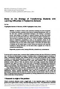
EEIA-2016 developed in FEM software, verified, adapted and adjusted to optimization procedure. Then the optimization algorithm should be selected, implemented in MATLAB software and coupled with numerical code. Figure 1 represents the general structure of the developed procedure for optimization of interrelated electromagnetic and temperature fields in different Electrical Engineering applications. It consists of two main blocks: optimization block and simulation block.
intensity. Some products like Cedrat FLUX have a possibility to export the developed model to the MATLAB library Simulink. It allows to model closedloop control systems, frequency-domain characteristics analysis and so on. All the mentioned advantages result in selection of program complex Cedrat FLUX for numerical modeling for educational purposes at SamSTU. Due to the embedded possibility of using Simulink, students usually develop the optimization procedure in MATLAB software.
3 Test case of using FLUX Cedrat FLUX is an application program package for finite-element analysis of electromagnetic and thermal processes both in 2D and 3D domains. FLUX is one of the most open products used for modeling and analysis of electromagnetic processes and systems because of the embedded command language based on Python and Java. This language allows user to create macros, which simplify all stages of modeling from geometry development to results analysis. This package has three modules: preprocessor, processor and postprocessor. Model's geometry, physical properties of materials and meshing are created in preprocessor. Next module is used for numerical simulation and analysis can be done in postprocessor. Switching between 2D and 3D domain types is realized in product working area. The main window of the software is shown in figure 2.
Fig. 1. General structure of optimization procedure
Optimization block implements solving of optimization problems using one of the well-known optimization methods or algorithms, for example, genetic algorithm NSGA [9, 10], alternance method of optimal control theory [11, 12], evolutionary methods [13], deterministic methods etc. Input data for this block are characteristics of interrelated electromagnetic and temperature fields; output is optimized process parameters. Simulation block contains numerical code for simulation the considered process developed in FEM software, for example, Cedrat FLUX, ANSYS, FEMLAB etc. Numerical model developed in any of the presented software can be used for optimization problem solution. Students at Samara State Technical University are used to developing a set of problem-oriented numerical models that can be adapted and integrated in optimization procedure in combination with any optimization method mentioned above. Conducted analysis shows that professional FEM software for numerical simulation of coupled electromagnetic and thermal fields can be divided by two big groups: universal multi-physics program packages and packages specially oriented for Electrical Engineering applications [7]. The obvious leader among software of the first group is program complex ANSYS. In the second group program package Cedrat FLUX has become widely spread in the recent years. Despite the fact that universal packages have obvious advantages, researcher can face difficulties in setting specific properties of particular process simulation. For example, some induction heating process properties like heat insulation modeling, workpiece movement, non-uniform initial temperature distribution, and design characteristics of induction heater cannot be easily specified in multi-physics software like ANSYS. Other advantages of specialized programs for simulation are easy-to-understand user interface and less resource
Fig. 2. FLUX main window
As it can be seen from the figure 2, user can open existing project or create new one by clicking on corresponding button. The main menu of the product is presented in figure 3. There are four general types of problems that can be simulated in FLUX: magnetic, electric, thermal and thermal coupled with magnetic or electric (fig. 4). Model geometry is developed via "Geometry" menu (fig. 5). This menu allows user to define some geometric parameters, symmetry, create new coordinate system, create points and lines etc. Meshing tools can be selected in menu "Mesh". FLUX allows user to select one of the embedded mesh generators or create new one with appropriate parameters, create mesh line or even mesh point (fig. 6). Physical properties of materials are defined in menu "Physics" (fig. 7). Then each geometric entity is assigned
2
SHS Web of Conferences 29, 02033 (2016)
DOI: 10.1051/ shsconf/20162902033
EEIA-2016 to physical region with defined material properties via "assign regions to geometric entities" menu entry. This menu is also used for creating electric circuits.
Fig. 7. Menu "Physics"
Other menus are used for changing display options, selecting geometric or mesh entities and viewing product help.
Fig. 3. Project menu
4 MATLAB-FLUX coupling 4.1 General information about MATLAB MATLAB is a high-performance programming language for engineer computations. Typically, MATLAB is used for mathematical computations, algorithms creation, modeling, data analysis and visualization, application development including graphical interface creation. It was developed specially for easy access to LINPACK and EISPACK, which are modern software for matrix computations. Special groups of programs called toolboxes play an important role in MATLAB. They allow user to solve particular classes of problems. They are used for signal handling, control systems, neural networks, fuzzy logic, etc. Simulink being a part of MATLAB is an interactive system for nonlinear dynamic systems modeling. It is a working environment allowing process modeling as a set of blocks connected between each other. Simulink works with linear, nonlinear, continuous and discrete systems. Block-sets are additions to Simulink, which provide block libraries for different special applications, for instance, signal handling or energy systems.
Fig. 4. Application types
4.2 FLUX-Simulink coupling procedure As it was mentioned, FLUX has an embedded possibility to couple with Simulink. The procedure of coupling organized as follows: 1) Development of FLUX project (creation of geometry, physics and mesh; definition of input and output parameters necessary for coupling); 2) Generation of FLUX-MATLAB Simulink component; 3) Opening MATLAB Simulink from FLUX Supervisor; 4) Development of Simulink model (adding and definition of FLUX-Simulink coupling library; adding, definition and connection of other necessary libraries around the coupling block); 5) Configuration of the simulation parameters; 6) Starting the simulation; 7) Analysis of results.
Fig. 5. Menu "Geometry"
Fig. 6. Menu "mesh"
3
SHS Web of Conferences 29, 02033 (2016)
DOI: 10.1051/ shsconf/20162902033
EEIA-2016 The first step of this procedure has already been described in section 3 of the paper. The next step requires the definition of the desired input and output parameters of FLUX model. As the coupling between FLUX and Simulink uses multiphysics co-simulation all input parameters must be defined as parameters of multiphysics type (fig. 8).
will remain inactive. After pressing the MATLAB button this software runs automatically and main MATLAB window appears. Figure 10 shows location of new Flux_Link library in Simulink.
Fig. 10. Simulink library browser with Flux_Link library
The "Coupling with Flux" block has several parameters, including name of the generated component, minimum, input variation in "Solver" menu and memory options, which are shown in figure 11.
Fig. 8. Parameter of multiphysics type
The following parameters can be defined as outputs of the FLUX project: a geometric parameter; an input/output parameter of non-multiphysics type; a predefined parameter of a mechanical assembly or a sensor. Once all the necessary inputs and outputs are available the user must generate a component for coupling via menu "Solving/Generate a component for MATLAB/Simulink coupling" (fig. 9). Fig. 11. Parameters of "Flux_Link" block
Mixed input/outputs point allows user to choose between individual representation - connection for each input and output or vector representation - a common connection for all inputs and outputs. Once the parameters of block are defined, user can connect all blocks and run the coupled simulation. For example, in considered case the input parameter is the value of power supply voltage and the output is temperature distribution within single point on the surface of the billet. The Simulink model of the system is presented in figure 12.
Fig. 9. Generation of MATLAB-FLUX component window
A component file should be created in the same directory and have the same name as the corresponding FLUX project. After the creation of the coupling component user needs to run MATLAB from FLUX Supervisor by clicking on MATLAB button on the main window (fig. 2). It should be noticed that user must define the location of MATLAB .exe file first in "Options/Access paths/Coupled software/Matlab", otherwise this button
Fig. 12. Simulink model
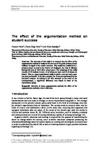
Test simulation time is 500 seconds and the value of voltage is 470 V. Figure 13 shows how the temperature in surface of the billet varies over time.
4
SHS Web of Conferences 29, 02033 (2016)
DOI: 10.1051/ shsconf/20162902033
EEIA-2016
Acknowledgments This research was partially supported by the Ministry of Education and Science of the Russian Federation (basic part of government contract, project No. 1436).
References 1. 2. 3. 4.
Fig. 13. Time-temperature history in the surface point of the billet
5 Conclusions
5.
This paper is devoted to detailed presentation of automatic optimization procedure which consists of coupled simulation and optimization blocks. As an example of simulation block the numerical code for FEM analysis of interrelated electromagnetic and temperature fields has been developed in professional program package Cedrat FLUX for Electrical Engineering applications. Program complex MATLAB has been chosen as a software for implementation of optimization block due to embedded FLUX function of coupling with Simulink as a part of MATLAB. FLUX-MATLAB coupling procedure is described and Simulink model is presented as a test case of integration of optimization and simulation blocks. The developed optimization procedure is used for a various research and teaching purposes in Engineering HE at SamSTU.
6. 7.
8. 9. 10. 11. 12. 13.
5
P. Di Barba, M. Forzan, E. Sieni, IJAEM, 47, 1003 (2015) P. Di Barba, Multiobjective shape design in electricity and magnetism (Springer, 2010). P. Di Barba, I. Dolezel, P. Karban, P. Kus, F. Mach, M.E. Mognaschi, et al. Inverse Problems in Science and Engineering, 22, 1214 (2014) V.V. Konushenko, First step in MATLAB (1998) Retrieved from http://www.matlab.exponenta.ru/ml/book3/index.ph p Cedrat FLUX. Retrieved from http://www.cedrat.com/en/software/flux.html (2016) ANSYS. Retrieved from http://www.ansys.com/Products/Academic (2016) Yu. Pleshivtseva, O. Sharapova, V. Mednikova Comparative analysis of program products Ansys and Cedrat FLUX conducted on test models of continuous induction heating installation, In XIII Int. conf. of CSCMP, 1, 78 (2011) Yu. Pleshivtseva, B. Nacke, A. Popov, AMM, 792, 462 (2015) K. Deb, A. Pratap, S. Agarwal, T. Meyarivan, IEEE Trans. on Evolutionary Computation, 6, 182 (2002) N. Srinivas, K. Deb, IEEE Trans. on Evolutionary Computation, 2, 221 (1994) E. Rapoport, Yu. Pleshivtseva, Optimal control of induction heating processes (CRC Press, USA, 2007) E. Rapoport, Yu. Pleshivtseva, OIDP, 48, 429 (2012) D. Simon, IEEE Trans. on Evolutionary Computation, 12, 702 (2008)