MECHANICS OF MATERIALS. FourthEdition. Beer • Johnston • DeWolf. 2 -2.
Contents ... Chapter 2 is concerned with deformation of a structural member
under.
Fourth Edition
CHAPTER
MECHANICS OF MATERIALS Ferdinand P. Beer E. Russell Johnston, Jr. John T. DeWolf
Stress and Strain – Axial Loading
Lecture Notes: J. Walt Oler Texas Tech University
© 2006 The McGraw-Hill Companies, Inc. All rights reserved.
Fourth Edition
MECHANICS OF MATERIALS
Beer • Johnston • DeWolf
Contents Stress & Strain: Axial Loading Normal Strain Stress-Strain Test Stress-Strain Diagram: Ductile Materials Stress-Strain Diagram: Brittle Materials Hooke’s Law: Modulus of Elasticity Elastic vs. Plastic Behavior Fatigue Deformations Under Axial Loading Example 2.01 Sample Problem 2.1 Static Indeterminacy Example 2.04 Thermal Stresses Poisson’s Ratio © 2006 The McGraw-Hill Companies, Inc. All rights reserved.
Generalized Hooke’s Law Dilatation: Bulk Modulus Shearing Strain Example 2.10 Relation Among E, ν, and G Sample Problem 2.5 Composite Materials Saint-Venant’s Principle Stress Concentration: Hole Stress Concentration: Fillet Example 2.12 Elastoplastic Materials Plastic Deformations Residual Stresses Example 2.14, 2.15, 2.16 2-2
Fourth Edition
MECHANICS OF MATERIALS
Beer • Johnston • DeWolf
Stress & Strain: Axial Loading • Suitability of a structure or machine may depend on the deformations in the structure as well as the stresses induced under loading. Statics analyses alone are not sufficient. • Considering structures as deformable allows determination of member forces and reactions which are statically indeterminate. • Determination of the stress distribution within a member also requires consideration of deformations in the member. • Chapter 2 is concerned with deformation of a structural member under axial loading. Later chapters will deal with torsional and pure bending loads.
© 2006 The McGraw-Hill Companies, Inc. All rights reserved.
2-3
Fourth Edition
MECHANICS OF MATERIALS
Beer • Johnston • DeWolf
Normal Strain
P σ = = stress A
2P P σ= = 2A A
ε=
ε=
δ
L
= normal strain
δ
L
© 2006 The McGraw-Hill Companies, Inc. All rights reserved.
P σ= A 2δ δ ε= = 2L L 2-4
Fourth Edition
MECHANICS OF MATERIALS
Beer • Johnston • DeWolf
Stress-Strain Test
© 2006 The McGraw-Hill Companies, Inc. All rights reserved.
2-5
Fourth Edition
MECHANICS OF MATERIALS
Beer • Johnston • DeWolf
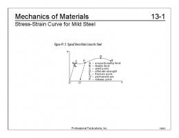
Stress-Strain Diagram: Ductile Materials
© 2006 The McGraw-Hill Companies, Inc. All rights reserved.
2-6
Fourth Edition
MECHANICS OF MATERIALS
Beer • Johnston • DeWolf
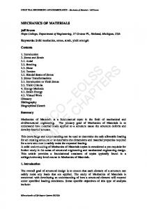
Stress-Strain Diagram: Brittle Materials
© 2006 The McGraw-Hill Companies, Inc. All rights reserved.
2-7
Fourth Edition
MECHANICS OF MATERIALS
Beer • Johnston • DeWolf
Hooke’s Law: Modulus of Elasticity
• Below the yield stress σ = Eε E = Youngs Modulus or Modulus of Elasticity
• Strength is affected by alloying, heat treating, and manufacturing process but stiffness (Modulus of Elasticity) is not.
© 2006 The McGraw-Hill Companies, Inc. All rights reserved.
2-8
Fourth Edition
MECHANICS OF MATERIALS
Beer • Johnston • DeWolf
Elastic vs. Plastic Behavior • If the strain disappears when the stress is removed, the material is said to behave elastically. • The largest stress for which this occurs is called the elastic limit. • When the strain does not return to zero after the stress is removed, the material is said to behave plastically.
© 2006 The McGraw-Hill Companies, Inc. All rights reserved.
2-9
Fourth Edition
MECHANICS OF MATERIALS
Beer • Johnston • DeWolf
Fatigue • Fatigue properties are shown on S-N diagrams. • A member may fail due to fatigue at stress levels significantly below the ultimate strength if subjected to many loading cycles. • When the stress is reduced below the endurance limit, fatigue failures do not occur for any number of cycles.
© 2006 The McGraw-Hill Companies, Inc. All rights reserved.
2 - 10
Fourth Edition
MECHANICS OF MATERIALS
Beer • Johnston • DeWolf
Deformations Under Axial Loading • From Hooke’s Law:
σ = Eε
ε=
σ E
=
P AE
• From the definition of strain:
ε=
δ
L
• Equating and solving for the deformation, PL δ = AE • With variations in loading, cross-section or material properties, PL δ =∑ i i i Ai Ei © 2006 The McGraw-Hill Companies, Inc. All rights reserved.
2 - 11
Fourth Edition
MECHANICS OF MATERIALS
Beer • Johnston • DeWolf
Example 2.01 SOLUTION: • Divide the rod into components at the load application points. E = 29 × 10
−6
psi
D = 1.07 in. d = 0.618 in.
Determine the deformation of the steel rod shown under the given loads.
© 2006 The McGraw-Hill Companies, Inc. All rights reserved.
• Apply a free-body analysis on each component to determine the internal force • Evaluate the total of the component deflections.
2 - 12
Fourth Edition
MECHANICS OF MATERIALS SOLUTION: • Divide the rod into three components:
Beer • Johnston • DeWolf
• Apply free-body analysis to each component to determine internal forces, P1 = 60 × 103 lb P2 = −15 × 103 lb P3 = 30 × 103 lb
• Evaluate total deflection, Pi Li 1 ⎛ P1L1 P2 L2 P3 L3 ⎞ ⎟⎟ = ⎜⎜ + + A E E A A A i i i ⎝ 1 2 3 ⎠
δ =∑
(
) (
) (
)
⎡ 60 × 103 12 − 15 × 103 12 30 × 103 16 ⎤ + + = ⎥ 6⎢ 0.9 0 .9 0 .3 29 × 10 ⎣⎢ ⎦⎥ 1
= 75.9 × 10⁻³ in.
L1 = L2 = 12 in.
L3 = 16 in.
A1 = A2 = 0.9 in 2
A3 = 0.3 in 2
© 2006 The McGraw-Hill Companies, Inc. All rights reserved.
δ = 75.9 × 10⁻³ in.
2 - 13
Fourth Edition
MECHANICS OF MATERIALS
Beer • Johnston • DeWolf
Sample Problem 2.1 SOLUTION:
The rigid bar BDE is supported by two links AB and CD.
• Apply a free-body analysis to the bar BDE to find the forces exerted by links AB and DC. • Evaluate the deformation of links AB and DC or the displacements of B and D.
• Work out the geometry to find the Link AB is made of aluminum (E = 70 deflection at E given the deflections GPa) and has a cross-sectional area of 500 at B and D. mm2. Link CD is made of steel (E = 200 GPa) and has a cross-sectional area of (600 mm2). For the 30-kN force shown, determine the deflection a) of B, b) of D, and c) of E. © 2006 The McGraw-Hill Companies, Inc. All rights reserved.
2 - 14
Fourth Edition
MECHANICS OF MATERIALS
Beer • Johnston • DeWolf
Sample Problem 2.1 SOLUTION:
Displacement of B: δB =
Free body: Bar BDE
PL AE
( − 60 × 103 N )(0.3 m ) = (500 ×10-6 m2 )(70 ×109 Pa ) = −514 × 10 − 6 m
∑MB = 0 0 = −(30 kN × 0.6 m ) + FCD × 0.2 m
δ B = 0.514 mm ↑
Displacement of D:
FCD = +90 kN tension
δD =
PL AE
0 = −(30 kN × 0.4 m ) − FAB × 0.2 m
( 90 × 103 N )(0.4 m ) = (600 ×10-6 m2 )(200 ×109 Pa )
FAB = −60 kN compression
= 300 × 10− 6 m
∑ MD = 0
δ D = 0.300 mm ↓ © 2006 The McGraw-Hill Companies, Inc. All rights reserved.
2 - 15
Fourth Edition
MECHANICS OF MATERIALS
Beer • Johnston • DeWolf
Sample Problem 2.1 Displacement of D: BB′ BH = DD′ HD 0.514 mm (200 mm ) − x = 0.300 mm x x = 73.7 mm EE ′ HE = DD′ HD
δE 0.300 mm
=
(400 + 73.7 )mm 73.7 mm
δ E = 1.928 mm δ E = 1.928 mm ↓ © 2006 The McGraw-Hill Companies, Inc. All rights reserved.
2 - 16
Fourth Edition
MECHANICS OF MATERIALS
Beer • Johnston • DeWolf
Static Indeterminacy • Structures for which internal forces and reactions cannot be determined from statics alone are said to be statically indeterminate.
• A structure will be statically indeterminate whenever it is held by more supports than are required to maintain its equilibrium. • Redundant reactions are replaced with unknown loads which along with the other loads must produce compatible deformations. • Deformations due to actual loads and redundant reactions are determined separately and then added or superposed.
δ = δL +δR = 0
© 2006 The McGraw-Hill Companies, Inc. All rights reserved.
2 - 17
Fourth Edition
MECHANICS OF MATERIALS
Beer • Johnston • DeWolf
Example 2.04 Determine the reactions at A and B for the steel bar and loading shown, assuming a close fit at both supports before the loads are applied. SOLUTION: • Consider the reaction at B as redundant, release the bar from that support, and solve for the displacement at B due to the applied loads. • Solve for the displacement at B due to the redundant reaction at B. • Require that the displacements due to the loads and due to the redundant reaction be compatible, i.e., require that their sum be zero. • Solve for the reaction at A due to applied loads and the reaction found at B. © 2006 The McGraw-Hill Companies, Inc. All rights reserved.
2 - 18
Fourth Edition
MECHANICS OF MATERIALS
Beer • Johnston • DeWolf
Example 2.04 SOLUTION: • Solve for the displacement at B due to the applied loads with the redundant constraint released, P1 = 0 P2 = P3 = 600 × 103 N A1 = A2 = 400 × 10− 6 m 2
P4 = 900 × 103 N
A3 = A4 = 250 × 10− 6 m 2
L1 = L2 = L3 = L4 = 0.150 m Pi Li 1.125 × 10⁹ δL = ∑ = A E E i i i
• Solve for the displacement at B due to the redundant constraint, P1 = P2 = − RB A1 = 400 × 10 − 6 m 2 L1 = L2 = 0.300 m
(
A2 = 250 × 10 − 6 m 2
)
Pi Li 1.95 × 10³ RB =− δR = ∑ A E E i i i © 2006 The McGraw-Hill Companies, Inc. All rights reserved.
2 - 19
Fourth Edition
MECHANICS OF MATERIALS
Beer • Johnston • DeWolf
Example 2.04 • Require that the displacements due to the loads and due to the redundant reaction be compatible, δ = δL +δR = 0
(
)
1.125 × 10⁹ 1.95 × 10³ RB − =0 δ = E E RB = 577 × 103 N = 577 kN
• Find the reaction at A due to the loads and the reaction at B ∑ Fy = 0 = R A − 300 kN − 600 kN + 577 kN R A = 323 kN R A = 323 kN RB = 577 kN
© 2006 The McGraw-Hill Companies, Inc. All rights reserved.
2 - 20
Fourth Edition
MECHANICS OF MATERIALS
Beer • Johnston • DeWolf
Thermal Stresses • A temperature change results in a change in length or thermal strain. There is no stress associated with the thermal strain unless the elongation is restrained by the supports. • Treat the additional support as redundant and apply the principle of superposition. PL δ T = α (∆T )L δP = AE α = thermal expansion coef. • The thermal deformation and the deformation from the redundant support must be compatible. δ = δT + δ P = 0
© 2006 The McGraw-Hill Companies, Inc. All rights reserved.
PL =0 AE P = − AEα (∆T ) P σ = = − Eα (∆T ) A
α (∆T )L +
2 - 21