IEEE TRANSACTIONS ON CIRCUITS SYSTEMS FOR VIDEO TECHNOLOGY
1
Memory-Efficient High-Speed Convolution-based Generic Structure for Multilevel 2-D DWT Basant Kumar Mohanty, Senior Member, IEEE, Pramod Kumar Meher, Senior Member, IEEE Abstract—In this paper, we have suggested a design strategy for the derivation of memory-efficient architecture for multi-level 2-D DWT. Using the proposed design scheme, we have derived a convolution-based generic architecture for the computation of 3-level 2-D DWT based on Daubechies as well as bi-orthogonal filters. The proposed structure does not involve frame-buffer and involves line-buffers of size 3(K − 2)M/4 which is independent of throughput rate, where K is the order of Daubechies/biorthogonal wavelet filter and M is the image height. This is a major advantage when the structure is implemented for higher throughput. The structure has regular data-flow, small cycle period TM and 100% hardware utilization efficiency. As per theoretical estimate, the proposed structure for image-size 512 × 512 and Daub-4 filter requires 152 more multipliers and 114 more adders, but involves 82412 less memory words and takes 10.5 times less time to compute 3-level 2-D DWT than the best of the existing convolution-based folded structures. Similarly, compared with the best of the existing lifting-based folded structures, proposed structure using 9/7-filter for the same image-size involves 93 more multipliers and 166 more adders, but uses 85317 less memory words and requires 2.625 times less computation time. It involves 90 (nearly 47.6%) more multipliers and 118 (nearly 40.1%) more adders, but requires 2723 less memory words than the recently proposed parallel structure and performs the computation in nearly half the time of the other. Inspite of having more arithmetic component than the liftingbased structures, the proposed structure offers significant saving in area and power over the other due to substantial reduction in memory size and smaller clock-period. ASIC synthesis result shows that, the proposed structure using Daub-4 involves 1.7 times less area-delay-product (ADP) and consumes 1.21 times less energy per image (EPI) than the corresponding best available convolution-based structure. It involves 2.6 times less ADP and consumes 1.48 times less EPI than the parallel lifting-based structure1 . Index Terms—Systolic array, VLSI, lifting, discrete wavelet transform (DWT), 2-dimensional (2-D) DWT.
I. I NTRODUCTION
T
WO dimensional (2-D) discrete wavelet transform (DWT) is widely used in image and video compression [1]. The input image is required to be decomposed into multilevel DWT to achieve higher compression ratio. The multilevel 2-D DWT on the other hand, being highly computation-intensive and memory-intensive, is implemented in VLSI system to meet the temporal requirement of real-time applications. Due to its ever increasing usage in high data-rate communication and storage, through portable and hand-held B. K. Mohanty is with the Dept. of Electronics and Communication Engineering, Jaypee University of Engineering and Technology, Raghogarh, Guna, Madhya Pradesh, India-473226, (email:
[email protected]). P. K. Meher is with the Department of Embedded Systems, Institute for Infocomm Research, 1 Fusionopolis Way, Singapore138632,(email:
[email protected]). 1 In case of existing structures, the power consumed for frame-buffer access is not accounted.
devices, VLSI implementation of 2-D DWT is subjected to a set of incompatible constraints. e. g., the silicon-area and power-consumption along with its minimum processing-speed for real-time computation. Several architectures have therefore been suggested in the last few years for constraint-driven VLSI implementation of 2-D DWT. Multilevel 2-D DWT can be implemented by recursive pyramid algorithm (RPA) [2]. But, the hardware utilization efficiency of the RPA-based structure is always less than 100%, and it involves complex control circuits. To overcome this problem, Wu et al [3] have suggested a folded scheme, where multi-level DWT computation is performed level-bylevel using one filtering unit and one external buffer. Unlike RPA-based designs, folded design involves simple control circuitry and it has 100 % HUE. In general, the folded structure consists of a pair of 1D DWT modules (row and column processor) and memory/storage components. The memory component consists of a frame-memory, transposition-memory and temporal-memory [6]. Frame-memory is required to store the low-low subband for level-by-level computation of multilevel 2-D DWT. Transposition-memory stores the intermediate values resulting from the row processing, while temporal-memory is used by the column processor to store the partial results. Framememory may either be on-chip or external, while the other two are on-chip memories. Transposition-memory size depends mainly on the type of data-access scheme adopted to feed the input data, while temporal-memory size depends on the number of intermediate data registers required by the 1D module to store the partial results. In general, the sizes of the transposition-memory and temporal-memory are some multiple of width of the input image, while the size of framememory is of the order of the image size. On other hand, the complexity of each 1-D module depends on the size of the wavelet filter and the computation scheme (convolution-based or lifting-based computation) is used to implement the filter. Since, the size of the images is usually very large compared to the size of the filter, complexity of memory component forms the major part of overall complexity of the 2-D structure. Cheng et al [7] have suggested a parallel data-access scheme to reduce the size of the transposition-memory. Folded structures based on this scheme requires 4N memory words for transposition and temporal memory [7], [10]. The memory requirement of [7] is the lowest among all the lifting 2-D DWT structures. Subsequently, Meher et al [8] have proposed a similar parallel data-access scheme for convolution-based folded structure. The structure of [8] computes 1-level 2D DWT and requires only (K + 2) memory access which is significantly less than others (convolution-based or liftingbased structures), where K is the order of the wavelet filter.
IEEE TRANSACTIONS ON CIRCUITS SYSTEMS FOR VIDEO TECHNOLOGY
power efficient multilevel 2-D DWT computation. We have shown that, the proposed structure involves nearly 30% less on-chip memory than the best of the existing similar liftingbased structure. Consequently, the area-delay-power saving is significant, although the proposed structure involves more arithmetic resources than the lifting structure. The remainder of the paper is organized as follows: The design strategy of proposed 2-D DWT based on parallel dataaccess scheme is discussed in Section II. Proposed architecture for multilevel 2-D DWT is described in Section III. Hardwarecomplexity and performance of the proposed structure are estimated and compared with existing architectures in Section IV. Conclusions are presented in Section V. II. D ESIGN S TRATEGY Before arriving at the proposed design scheme for memoryefficient structure of 2-D DWT, we review two such existing schemes to have insight into their advantages and disadvantages. We have observed that, parallel data-access scheme of [7] and [8] helps to reduce on-chip memory of the folded structure but at the same time it increases complexity of the frame-buffer. Efficiency of this scheme depends on the amount of memory saving it offers over the line-based scheme and the overhead cost in terms of frame-buffer complexity. To make this point more clear, we have reviewed the line-based design and folded design with parallel data access, and presented a comparative study on the hardware-complexity to identify their usefulness and limitations of the parallel-data-access scheme. From input‐buffer MUX
:
LH1 ... LH LHJ HH1 … HHJ HL1
… HLJ
RP
TN MEM TN‐MEM
CP
TL‐MEM LL1 LL3 .. .. LLJ‐2
DMUX LL1 … LLJ‐1
Buffer‐1 Buffer‐2 LL2 LL4 .. LLJ‐1
Fig. 1.
MUX X
2‐D DWT Processor
DMU UX
Hsia et al. [15] have suggested a symmetric mask-based algorithm for lifting 2-D DWT using 5/3 filters where separate masks are used for each subband. The 2-D DWT structure based on mask-based algorithm does not require temporal memory and demands a smaller transposition-memory than the conventional lifting-based structure, but it involves more multiplication and additions than others. This method is not found suitable for 9/7 filters due to its requirement of large mask and because of its multipliers can not be implemented by shifters only as they do in case of 5/3 filters. Recently we have proposed a parallel architecture for multilevel lifting 2-D DWT [13], which involves on-chip memory of size nearly 10N and process a block of P samples in every cycle. The major advantage of this structure is the saving of frame-buffer. But, input block-size of this design need to be an integer sub-multiple of the image width (N ). To achieve 100% hardware utilization efficiency (HUE), the minimum block size for J level DWT is 22J−1 . Since, the blocksize increases exponentially with J, a full parallel structure involves very high hardware requirement. Recently, Tian et al [14] have suggested a block-based design for high-throughput implementation 1-level 2-D DWT. Unlike the structure of [13], the on-chip memory of this structure, however, varies proportionately with the block-size. Zhang et al [17] have suggested a pipeline architecture for multilevel 2-D DWT using non-separable approach to avoid both transpositionmemory and frame-buffer. But non-separable 2-D DWT is not popular, since it demands K/2 times more computation than the separable 2-D DWT for the same throughput rate, where (K × K) is the order of the 2-D wavelet filter. We have observed that, in the parallel structure of [13] arithmetic complexity of DWT levels decreases progressively by one-fourth as we go to the next higher level, but the memory complexity decreases only by half. This happens due to repeated folding of the data-blocks after every level of decomposition to achieve 100% HUE. Also the structure requires separate interface units (consisting of data-selectors and memory) to fold the data-blocks. The interface unit and the on-chip memory affect the speed and power performance of the parallel structure significantly. Instead of folding of data-blocks, row and column processing of DWT levels could be folded to achieve 100% HUE. By this method memorycomplexity also can be reduced by one-fourth after every level of decomposition progressively, like that of arithmetic complexity. The lifting-scheme, although has lower arithmetic complexity, does not favor row and column folding due to temporal-memory. Convolution–based implementation has potential for better solution than the lifting-based one, because the direct form convolution-based structure allows rowcolumn folding without using any temporal-memory. But, the convolution-based design demands larger-size transpositionmemory and arithmetic components than the lifting structure for same performance. Since arithmetic-complexity depends on the wavelet filter size which is significantly small compared to the image-size, the complexity of the transposition-memory could make the convolution-based design inefficient. Keeping these issues in mind, in this paper, we have suggested a transposition-free row-column folded structure for area-delay-
2
Frame‐Buffer
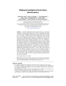
Generic structure of line-based folded 2-D DWT
A. Line-based Folded Structure Line-based folded structure referred as (LBF) is shown in Fig.1. It consists of one processor (for 1-level 2-D DWT), one transposition-memory (TN-MEM), temporal-memory (TLMEM) and frame-buffer (FB). The 2-D DWT processor is comprised of one row-processor (RP) and one columnprocessor (CP). RP operates on input data matrix of size (M ×N ). It performs row-wise processing and generates a pair of intermediate matrices [UL , UH ] of size (M × N/2) each. From TN-MEM, CP receives the components of [UL ] and
IEEE TRANSACTIONS ON CIRCUITS SYSTEMS FOR VIDEO TECHNOLOGY
MUX‐ARRAY
: RP
2‐D DWT Processor
TL‐MEM
CP LH1 LH2 … HH1 HH2 …
LL1
LL2
…
DMUX
HL1 HL2 …
B ff 1 Buffer‐1
:
Buffer 2 Buffer‐2
:
:
Frame‐Buffer
LL2 LL4 … (even‐numbered levels)
Fig. 2. scheme
MUX‐ARRA AY
LL1 LL3 … (odd‐numbered levels) (odd‐numbered levels) DMUX
Generic structure of folded 2-D DWT using parallel-data-access LL
SR-(K-2)
SR-(K-3)
SR-4
SR-3
MB-2 (MN/8)
SR-2
MB-1 (MN/8)
SR-1
DMUX
P samples
(a)
xin
Single-port RAM-2
RW
(b)
MUX
Single-port RAM-1
Addr
xout
Fig. 3. (a) Structure of Buffer-1. (b) Structure of shift-register using singleport RAM 4000 3500 Memory SSaving (word ds)
The folded structure with parallel data-access referred as (PDAF) is shown in Fig.2. A block of Q samples is fed to the processor in every cycle. Input blocks are prepared from a set of Q consecutive columns of the data matrix such that adjacent sets of columns are overlapped by Q − 2 columns, where Q = 3 for lifting-DWT and Q = K − 2 for convolution-DWT. RP generates intermediate components column-wise and these components are directly fed to the CP without transposing. Using parallel data-access, TN-MEM is avoided but that introduces some additional complexity to the FB of the folded 2-D DWT, since the FB receives LL subbands from the processor in serial order and feeds those components block-by-block back to the processor. Each buffer (Buffer-1 and Buffer-2) of the FB is designed accordingly. Structure of Buffer-1 is shown in Fig.3. It consists of two memoryblocks (MBs) of size (M N/8) words each and (Q − 2) shiftregisters (SRs) of size M/2 words. SRs are used to introduce down-sampling and necessary column overlapping in the datablocks. LL subband is splitted into even and odd columns by the DMUX. Even-numbered columns are buffered in MB-2, while the odd-numbered-columns are buffered in MB-1. But the columns are retrieved simultaneously from MB-1 and MB2 in the same column serial order as they were stored. SRs stores (Q−2) recent past columns. From Buffer-1, data-blocks of Q consecutive columns are obtained, where successive sets of columns are overlapped by (Q − 2) columns. Structure and operation of Buffer-2 is similar to Buffer-1 but in this case the size of each MB and SRs is M N/32 words and M/4 words, respectively. The MUX-array (shown in Fig.2) selects the data-block from these buffers alternatively during alternate decomposition levels. Each SR can be implemented using a pair of single-port RAM of size M/2 words and one MUX (shown in Fig.3(b)). Due to different size of MBs used in Buffer-1 and Buffer-2, different address signals are required for read/write operation. The control circuit required for the operation of the FB is, therefore, quite complex.
:
B. Folded Design using Parallel Data-Access Technique
From input‐buffer
:
[UH ] column-wise and processes them to generate four subband matrices [LL1 , LH 1 , HL1 , HH 1 ] of size (M/2 × N/2) each. CP requires a TL-MEM for temporary storage of partial results of filtering operation. Sizes of TN-MEM and TL-MEM are (2Q − 1)N/2 words and Q0 N words, respectively, where Q represents the minimum number of rows of the intermediate components to be buffered to initiate column processing and Q0 represents the number of lifting steps for lifting-based filter computation. For convolution-based computation of DWT Q = K and Q0 = 0. For lifting-based computation of DWT, Q = 3 and Q0 = Kl , where Kl is the lifting-steps of the bi-orthogonal filter (for example: Kl = 2 for 5/3 filter and Kl = 4 for 9/7 filter). The LL1 subband is stored in FB. The processor starts receiving data from FB soon after it completes the first-level computation. FB is comprised of two memory units (Buffer-1 and Buffer-2), where buffer-1 stores LL subband of odd-numbered levels and buffer-2 stores LL subband of even-numbered levels. Buffer-1 and Buffer-2 are of size M N/4 and M N/16 words, respectively.
3
3000 2500 2000 1500 1000 500 0 Daub‐4
Daub‐6
Daub‐8
Daub‐10
5/3 (CONV)
9/7 (CONV)
5/3 (Lifting)
9/7 (Lifting)
Filters
Fig. 4. Memory saving offered by the parallel data-access scheme over line-based scheme for image 512 × 512.
C. Complexity Analysis The words volves 3Q − volves and 4
FB of LBF structure involves (5M N/16) RAM and one MUX, while FB of PDAF structure in(5M N/16 + 3M (Q − 2)/2) RAM words and 2 MUXes/DMUXes. LBF structure, therefore, in(5M N/16 + (2Q − 1)N + 2Q0 N ) RAM words MUXes/DMUXes while PDAF structure involves
IEEE TRANSACTIONS ON CIRCUITS SYSTEMS FOR VIDEO TECHNOLOGY
4
TABLE I C OMPARISON OF HARDWARE COMPLEXITY OF FOLDED STRUCTURES BASED ON LINE AND PARALLEL ACCESS FOR DIFFERENT DWT SCHEMES AND WAVELET FILTERS
Line-by-line data access
DWT
Filter
scheme
TN-MEM
TL-MEM
FB
(2Q − 1)N
2Q0 N
δ
MUX
Parallel-data-access control
TN-MEM
TL-MEM
FB
MUX
2Q0 N
β
4Q
control
Daub-4
convolution
7N
0
δ
4
simple
0
0
δ + 3M
16
complex
Daub-6
convolution
11N
0
δ
4
simple
0
0
δ + 6M
24
complex
Daub-8
convolution
15N
0
δ
4
simple
0
0
δ + 9M
32
complex
Daub-10
convolution
19N
0
δ
4
simple
0
0
δ + 12M
40
complex
5/3
convolution
9N
0
δ
4
simple
0
0
δ + 9M/2
20
complex
9/7
convolution
17N
0
δ
4
simple
0
0
δ + 21M/2
36
complex
5/3
lifting
5N
4N
δ
4
simple
0
4N
δ + 3M/2
12
complex
9/7
lifting
5N
8N
δ
4
simple
0
8N
δ + 3M/2
12
complex
Memoryy‐cost to m memory savving (in %)
TN-MEM, TL-MEM and FB size are represented in RAM words (single-port). δ = 5M N/16 and β = δ + 3M (Q − 2)/2, for convolution-DWT Q = K and Q0 = 0, and for lifting-DWT Q = 3 and Q0 = Kl , where K is the order of the wavelet filter and Kl is the lifting steps. Kl = 2 for 5/3 filter and Kl = 4 for 9/7 filter.
70 60 50 40 30 20 10 0
Daub‐4
Daub‐6
Daub‐8 Daub‐10
5/3 / (CONV)
9/7 / 5/3 / 9/7 / (CONV) (Lifting) (Lifting)
folded structures involve TL-MEM. As a consequence, the onchip memory of the lifting-based structure with parallel dataaccess scheme involves some line-buffers. On the other hand, convolution-based structure with parallel-data-access scheme does not involve TM-MEM and TL-MEM. This becomes a major advantage to design a memory-efficient structure if multilevel DWT computations are scheduled appropriately without using FB, since the advantage of parallel-data-access scheme is compensated by the overhead cost of the FB. In [13], we have shown that FB can be eliminated by processing DWT levels concurrently in a pipeline structure.
Filter
D. Proposed Design Strategy Fig. 5. Overhead memory-cost to memory-saving (CS) of the parallel dataaccess scheme for image size 512 × 512 and different wavelet filters.
(5M N/16 + 3M (Q − 2)/2 + 2Q0 N ) RAM words and 4Q MUXes/DMUXes. We have estimated hardware complexity of LBF and DPAF structures for different wavelet filters and DWT schemes (convolution and lifting) and listed in Table I for comparison. Since, the number of arithmetic components (multiplier and adder) involved by both the structures is the same, we have excluded these component while estimating the hardware-complexity for comparison purpose. As shown in Table I, parallel-data-access scheme eliminate TN-MEM but it increases memory size of the FB. We have estimated memory saving offered by the parallel data-access scheme over the line-based scheme for different wavelet filters and the values are plotted in Fig. 4 for image size 512 × 512. As shown in Fig. 4, parallel data-access scheme offers more memory saving in case of convolution-DWT than liftingDWT. To measure the efficiency of the parallel data-access scheme for different DWT schemes and filter orders, we have estimated the overhead memory cost to memory saving (CS), and the values are shown in Fig. 5. We observe from Fig. 5 that, CS is the lowest in lifting-DWT and does not increase with filter order in case of bi-orthogonal filters, while in case of Daub filters, it increases with filter order. The lifting-based
Lifting-based scheme has been considered more efficient compared with the convolution-based approach due to its lower arithmetic complexity. But, after a thorough analysis of both lifting and the convolution-based designs, we observe that, convolution-based scheme along with appropriate scheduling of multi-level decomposition could have lower complexity than the lifting-based design. The memory saving offered by the convolution-based scheme is significantly higher than the saving of arithmetic components. Also we observe that, the existing folded and block-based designs have some inherent difficulty to reduce the memory complexity of the 2-D DWT structures. Although the block-based design of [13] eliminates the requirement of frame-buffer for the multilevel DWT computation and utilizes on-chip memory-efficiently. It involves required larger on-chip memory and introduces significant overhead in terms of input-interface units. To overcome the above difficulties we propose here a scheme to derive a memory efficient computing structure for multilevel 2-D DWT. • •
•
DWT levels are computed concurrently to avoid framebuffer. Convolution scheme is used for orthogonal as well as biorthogonal wavelet filters to take maximum advantage of parallel-data-access scheme. Parallel data-access is applied in each DWT level to reduce memory complexity of the overall structure.
IEEE TRANSACTIONS ON CIRCUITS SYSTEMS FOR VIDEO TECHNOLOGY
III. P ROPOSED A RCHITECTURE Due to down-sampled filtering, the computational complexity after each level of decomposition steadily decreases by a factor of four. In order to achieve 100% HUE, hardware resource of the processing units (PUs) should be reduced by a factor of 4 after every DWT level. But we do not have any suitable straight-forward approach to map the DWT computation of successive levels to the PU with one-forth complexity. Maximum (100%) HUE may be achieved by introducing four times more parallelism in two-level DWT computation. Similarly, for three-level DWT, we need to have 16 times more parallelism which could be too high for many applications. Alternatively, if we assume hardware resource of a PU can be reduced upto one subcell comprised of a pair of low-pass and a high-pass filters, then PU-J corresponding to J-th level is comprised of one subcell and processes 2 samples in every cycle for 100% HUE, where the row and column computations are time-multiplexed. The overall throughput rate of PU-J is one sample per cycle. We have estimated the minimum input block-size for different DWT levels (shown in Table II) to achieve 100% HUE of the possible structures based on the proposed scheme. TABLE II M INIMUM INPUT BLOCK - SIZE FOR DIFFERENT DWT LEVELS DWT Levels (J)
Input-block size (P )
1
1
2
4
3
16
4
64
5
256
Based on these observations, we have derived a pipeline structure for three-level 2-D DWT. However, similar structures can be derived for higher DWT levels as well. The proposed structure is shown in Fig.6. It consists of three processing units (PUs), where PU-1, PU-2 and PU-3, respectively, perform computations of first-level, second-level and third-level. With
reference to Table II, minimum input block-size for PU-1 is P = 16. Structure of PU-1 is shown in Fig.7. It consists of 8 processing elements (PEs). Each input-block is extended by (K − 2) samples such that adjacent input-blocks of a row are overlapped by (K − 2) samples, where K is the filter order. From the input matrix (X), extended input-blocks (I(m, i)) are fed to PU-1 block-by-block in every cycle. The input block I(m, i) corresponding to the m-th row of (X) contains the samples {x(m, 16i), x(m, 16i+1), ···, x(m, 16i+ K + 12), x(m, 16i + K + 13)}, for 0 ≤ m ≤ M − 1 and 0 ≤ i ≤ (N/16) − 1. Suppose in the first cycle, the first input block of the first row of X is fed then during the second cycle, the first input block of the second row is fed to PU1, such that the first input blocks of all the M rows of X are fed in M cycles and in the next set of M cycles, second input blocks of all the M rows are fed to the structure. The entire M N/16 input blocks of X are fed to the structure in M N/16 cycles. The input-buffer is an interleaved memory consists of P banks (shown in Fig.8) to read a block of P samples simultaneously. The input-buffer requires additional [2(K − 2)M ] single-port RAM words to store the overlapping columns such that overlapped input-blocks are read from the input-buffer. A set of 8 data-vectors (Bq+1 , for 0 ≤ q ≤ 7) of size K are derived from each input-block I(m, i) where the adjacent datavectors are overlapped by (K −2) samples. These data-vectors are fed in parallel to the PEs, such that (q + 1)-th PE receives the data-vector Bq+1 . Structure of PE is shown in Fig.9(a). It consists of a pair of identical subcells (subcell-1 and subcell-2) and one delay-unit (DU-1). Subcell-1 performs the necessary DWT computation along the row-direction where K consecutive samples of a particular row constitute the datavector. Structure of the subcell using orthogonal wavelet filters is shown in Fig.10(a). It consists of K multiplier-units (MUs), where each MU performs multiplication corresponding to a pair of low-pass (h(k) and high-pass g(k)) filter coefficients, for 0 ≤ k ≤ K − 1. Internal structure of the (k + 1)-th MU is shown in Fig.10(b). The low-pass and the high-pass partial results are added in two separate adder-trees to compute a pair of low-pass and high-pass filter outputs. Besides, each subcell involves an additional adder-unit to perform the computation of bi-orthogonal filters. The structure of the subcell using 9/7 filter is shown in Fig.11. The adder-unit (shown in Fig.12) generates intermediate signals si , for (0 ≤ i ≤ 4) for lowpass filter and ri , for (0 ≤ i ≤ 3) for high-pass filter to exploit the symmetric property of the bi-orthogonal filters. The intermediate signals passes through the MU and then the adder-tree to calculate the low-pass and high-pass filter outputs.
From Input‐b buffer
Due to down-sampled filter computation, appropriate block-size (P ) need to be selected for the first level such that parallel-data-access scheme could be applied to maximum possible DWT levels and 100% HUE could be achieved. • For resource-constrained application, input block-size (P ) is required to be decided depending on the availability resources. • RPA like computation with line-based scanning is considered to compute rest of the higher DWT level if the input block-size is not sufficient. Using the proposed scheme, we have derived a parallel and pipeline architecture for the computation of three-level 2-D DWT. The proposed structure is suitable for both Daubechies and bi-orthogonal wavelet filters (5/3 and 9/7). We have shown that, the proposed structure does not require framebuffer and involves significantly less on-chip memory than the existing structures and offers high-throughput rate. •
5
Fig. 6.
vlh1
vhh1 vll1
PU‐1 P samples / cycle
vhl1
vlh2
vhh2 vll2
PU‐2
PU‐3
vlh3 vhh3 vll3 vhl3
vhl2
Proposed structure for computation of three-level 2-D DWT.
6
x0
x1
xK‐2
xK‐1
MU 1 MU‐1
MU 2 MU‐2
MU (K 1) MU‐(K‐1)
MU (K) MU‐(K)
Derived from block of (K+14) samples B1 K
B2 K
B4 K
B5 K
B6 K
B7 K
3rd PE
4th PE
5th PE
6th PE
7th PE
B8 K
ADDER TREE‐1
8th PE
v1hh(m,n-1) v1hl(m,n-1) v1lh(m,n-1) v1ll(m,n-1) v1hh(m,n-2) v1hl(m,n-2) v1lh(m,n-2) v1ll(m,n-2) v1hh(m,n-3) v1hl(m,n-3) v1lh(m,n-3) v1ll(m,n-3) v1hh(m,n-4) v1hl(m,n-4) v1lh(m,n-4) v1ll(m,n-4) v1hh(m,n-5) v1hl(m,n-5) v1lh(m,n-5) v1ll(m,n-5) v1hh(m,n-6) v1hl(m,n-6) v1lh(m,n-6) v1ll(m,n-6) v1hh(m,n-7) v1hl(m,n-7) v1lh(m,n-7) v1ll(m,n-7)
2nd PE
v1hh(m,n) v1hl(m,n) v1lh(m,n) v1ll(m,n)
1st PE
B3 K
P Pipeline
IEEE TRANSACTIONS ON CIRCUITS SYSTEMS FOR VIDEO TECHNOLOGY
ADDER TREE‐2 ADDER TREE 2 Low-pass output
((a))
high-pass output
xk
Input for PU‐2
h(k)
g(k)
(b)
Fig. 7.
Structure of PU-1 Fig. 10. (a) Structure of the subcell with orthogonal wavelet filters. (b) Structure of (k + 1)-th MU Input 2‐D data (row‐by‐row)
MUX
Size (MN/P)
x0
x1
x2
x3
x4
DMUX
x6
x7
x8
ADDER UNIT ADDER‐UNIT s0
Size (MN/P)
Module‐2 Module 2 Module‐1
x5
Size (MN/P)
Module (P 1) Module‐(P‐1)
Size (MN/P)
s1
MU‐1 MU 1
s2
MU‐2 MU 2
s3
MU‐3 MU 3
r1
r0
s4
MU‐4 MU 4
r3
r2
Pipelinee
Select signal Addr1
Size (M)
Size (M)
Size (M)
Size (M)
RW Addr2 Overhead
h(4)
M d l (P) Module‐(P)
ADDER TREE 1 ADDER‐TREE‐1
MUX
F From Module‐(K‐2) M d l (K 2) (K‐2) copies
ADDER‐TREE‐2
O l Overlapped output data block spreading over of size (P+K‐2) rows d d bl k di f i (P K 2)
Low‐pass p High‐pass g p output output
Fig. 8. Structure of the input-buffer using interleaved-memory and singleport RAM to enable overlapped data-blocks of size (P + K − 2). M and N , respectively, the height and width of the image, P is the block-size and K is the order of the wavelet filter.
Fig. 11.
x0
x(m,2i-K+1) x(m,2i-1) x(m,2i-K+2) x(m,2i) u1l
Subcell‐1
x1
x2
x3
x4
x5
x6
x7
x8
u1h
MUX
Delay‐unit y Subcell‐2 Subcell 2
Structure of the subcell with 9/7-biorthogonal wavelet filter.
R1 R2
R3 R4
R2K‐5 R2K‐4 2K 4
R2K‐3 R2K‐2 2K 2
Fig. 12.
+
+
+
+
s0
s1
s2
s3
s4
+
+
+
r0
r1
r2
r3
Structure of the adder-unit.
.. DMUX v1hh(m,i) (m i) v1lh(m,i)
DMUX v1ll(m,i) (m i) v1hl(m,i) (a)
K samples/cycle (b)
Fig. 9. (a) Structure of the processing element (PE). (b) Structure of delayunit (DU-1)
Subcell-1 of PE generates a pair of low-pass (ul ) and highpass (uh ) intermediate components in each cycle. Successive outputs of subcell-1 belongs to the same column. Subcell-2 does the processing of the intermediate matrices [Ul ] and [Uh ] column-wise in time-multiplexed form to take the advantage of down-sampled DWT computation. The delay-unit (DU-
1) provides the necessary column delay to the intermediate results and feeds them into subcell-2 in time-multiplexed form to perform down-sampled DWT computation. Internal structure of the DU-1 is shown in Fig.9(b). During every even-numbered cycles, suppose the low-pass components ul (m, n) are available at the MUX so that during the same cycle, (K − 1) consecutive components of the n-th column {ul (m − 1, n), ul (m − 2, n), · · ·, ul (m − K + 1, n)} are available at the even-numbered registers. During the oddnumbered cycles, high-pass components of the same n-th column {uh (m, n, uh (m − 1, n), · · ·, uh (m − K + 1, n)} are, respectively, available at the MUX and the same evennumbered registers. Subcell-2, therefore, receives components of ul during every even-numbered cycles and those of uh during every-odd numbered cycles. One component of a pair
IEEE TRANSACTIONS ON CIRCUITS SYSTEMS FOR VIDEO TECHNOLOGY
Bi+1 (K samples) u2l u2h
R1
R2
R4
R3
R5
MUX
.. ..
R2K‐4
R2K‐2
R2K‐3
R2K‐1
..
MUX
MUX
MUX
R Register‐ ‐array
1 1 1 subband [vll1 , vlh ] or [vhl , vhh ] are obtained from each PE in every cycle and one component of each of four subbands are obtained in a couple of cycles. A block of 8 components of a particular row of four subbands are obtained from PU-1 in every two cycles such that 8 columns of four subbands are obtained in M cycles. First-level DWT of the entire input matrix is obtained in M N/16 cycles.
7
Arithmetic‐core v1ll from PU-1(8 samples/2 cycles) SR R‐array
K
hl(m,n-i)
v2ll(m,n-i)
Structure of (i + 1)-th FE-I.
K
3) lh(m,n-3
v2ll(m,n-3 3)
v2
v2hh(m,n-3 3)
4th FE‐I FE I v2ll(m,n-2 2)
v2hl(m,n-2 2)
lh(m,n-1)
Fig. 14.
v2lh(m,n-i)
DMUX
v2
B4
3rd FE‐I FE I v2ll(m,n-1 1)
v2
v2hl(m,n-1)
v2hh(m,n-1 1)
v2ll(m,n n)
v2hh(m,n-i)
Input for PU‐3 Fig. 13.
DMUX
DMUX
v2hl(m,n-3 3)
K 2nd FE‐I FE I
v2hh(m,n-2 2)
K 1st FE‐I FE I v2lh(m,n n)
(K+6) samples B3
B2
v2lh(m,n-2 2)
B1
v2hl(m,n n)
.. ..
..
v2hh(m,n n)
SR R‐(K‐2)
SSR‐2
..
SSR‐1
DMUX
Structure of PU-2.
Components of low-low subband vll1 are processed by PU-2 to compute DWT components of second-level. PU-2 receives a block 8 components of a particular row of vll1 from PU-1 in every cycle after a gap of one cycle. The structure of PU-2 is shown in Fig. 13. It consists of one shift-register (SR)array and four functional elements (FEs) of type FE-I. The data-input format of PU-2 is the same as that of PU-1. Each input-block is extended by (K − 2) samples and the adjacent input-block of a row is overlapped by (K − 2) samples. The (K − 2) previous columns of vll1 are, therefore, required to be stored to provide the necessary data-extension and block overlapping. The SR-array, therefore, contains (K − 2) shiftregisters (SRs) of M/2 words each. SR-array also introduces embedded down-sampling along the rows of second-level DWT computation. Input-blocks of vll1 arrives at PU-2 columnwise after a gap of one cycle such that one column of the inputblocks of vll1 arrives at the PU-2 in M cycles, and input-blocks of the entire subband vll1 in M N/16 cycles. Each input-block arriving at PU-2 are extended by (K − 2) samples produced by the SR-array. Four overlapped datavectors of size K are derived from each extended-blocks of size (K +6) in the similar format as that of the first-level. The data-vectors are fed to the FEs in parallel, such that (i + 1)-th FE-I receives the data-vector Bi+1 , where Bi+1 of input-block I(m, n) contain the samples {vll1 (m, 8n+2i), vll1 (m, 8n+2i+ 1), · · ·, vll1 (m, 8n + 2i + K − 1), for 0 ≤ m ≤ (M/2) − 1, 0 ≤ n ≤ (N/16) − 1 and 0 ≤ i ≤ 3. Structure of FE-I is shown in Fig14. It consists of one arithmetic-core (ARC), one register-array and four DMUXes. The structure of ARC is same as the subcell-1 of Fig.10(a) or Fig.11. ARC of each FEI calculates a pair of intermediate components u2l (m, n) and u2h (m, n). Note that the successive output samples u2l (m, n)i
and u2h (m, n)i correspond to the same column of intermediate coefficient matrix ([u2l ] and [u2h ]). Since PU-2 receives the input-blocks of vll1 only during the alternate cycles, ARC of each FE-I remains free for one cycle after every input cycle of I(m, n). These free cycles of the ARC are utilized by assigning down-sampled filter computation of ([u2l ] and [u2h ]) in timemultiplexed form. The samples of u2l (m, n)i and u2h (m, n)i corresponding to (i+1)-th FE-I are passed through the registerarray (shown in Fig.14) to provide the column delay necessary for the down-sampled filter computation. All the registers of the register-array and shift registers of SR-array are clocked by CLK2 whose frequency is half of the frequency of CLK1 used by PU-1. Multiplexer selects the delayed samples of u2l , and u2h alternately and feeds them to the ARC during the idle 2 ) cycles. A pair of DWT components of two subbands (vll2 , vlh 2 2 or (vhl , vhh ) are obtained from each FE-I after every couple of cycles and one component of each of four subbands in every four cycles. A block of four components (consisting of one from each of the four subbands) are obtained from four FE-I. Four columns of each of the four subbands are obtained from PU2 in M cycles and subband components of second-level DWT are obtained in N M/16 cycles. Components of subband vll2 are sent to PU-3 to compute third-level DWT. PU-3 receives a block of four components corresponding to four consecutive columns of vll2 from PU-2 in every forth-cycle. The data-input format of PU-3 is the same as that of PU-2. (K − 2) previous columns of vll2 are buffered in the SR-array to provide the necessary data-extension to each input-block. The size of each SR in this case is M/4 words. The structure of PU-3 is shown in Fig. 15. It consists of one delay-unit (DU-3) and one FE-II. Input-blocks of vll2 arrives at PU-3 column-wise after every-forth cycle such that one column of the input-blocks of vll2 arrives at the PU-2 in M cycles and all input-blocks of the entire subband vll2 in M N/16 cycles. Two overlapped data-vectors of size K are derived from each extended-blocks (of size K + 2). Data-vectors (B1 and B2 ) of a particular extended-block are fed to the FE-II in alternate cycles. In this way, B1 and B2 of all the input-blocks are time-multiplexed and fed to the FE-II during every 4n and
IEEE TRANSACTIONS ON CIRCUITS SYSTEMS FOR VIDEO TECHNOLOGY
..
DU‐3
SR‐array
SR‐(K‐2)
..
SR‐5
SR‐4
SR‐1
4 samples/4cycles
.. ((K+2) samples ) B2 (Overlapped blocks)
B1
..
.. Latch
Latch
.. FE‐II v3lh(m,n) v3lh(m,n-1) v3ll(m,n-1) 3 (m,n) 3 v v3hh(m,n-1) v hl(m,n-1) hh v3hl(m,n)
v3ll(m,n)
Fig. 15.
Structure of PU-3.
(4n + 2) cycles. Data-vector B2 is latched in DU-3 and the MUXes of FE-II select B2 two cycles after B1 . Structure of the FE-II is shown in Fig16. It consists of two register-arrays and one ARC. The ARC receives the data-vectors (B1 and B2 ) of a particular input-block through the 4-to-1 line MUXes after a gap of two cycles. It computes a pair of intermediate components u3l (m, n) and u3h (m, n) corresponding to datavector B1 during every (4n+1) cycle. During every (4n+3)-th cycle, it computes (u3l (m, n−1), u3h (m, n−1)) corresponding to B2 . The successive intermediate outputs corresponding to B1 or B2 belong to the same columns. B1
B2
..
..
..
u3l(m,n) u3h(m,n)
REGISTER ARRAY‐1
..
u3l(m,n-1) u3h(m,n-1)
REGISTER ARRAY‐2 MUX
MUX
..
MUX
MUX
Arithmetic‐core DMUX
DMUX
DMUX
DMUX
v3ll(m,n) v3ll(m,n-1) v3hl(m,n) v3 (m,n-1) hl
Fig. 16.
DMUX v3
DMUX
lh(m,n) v3lh(m,n-1) v3hh(m,n) v3hh(m,n-1)
Structure of the FE-II.
Since the ARC receives the data-blocks at alternate cycle, it remains idle during odd-cycles. These idle cycles of the ARC are utilized by computing column-DWT of the all the intermediate components in a time-multiplexed form. Computation of u3l (m, n) and u3h (m, n) are scheduled at every (8n + 1)-th and (8n + 5)-th cycles, respectively, to take advantage of the down-sampled filter computation. Similarly, the computation of u3l (m, n − 1) and u3h (m, n − 1) are scheduled at every (8n + 3)-th and (8n + 7)-th cycles, respectively. The register-
8
array-1 provides the necessary column delay to the samples of u3l (m, n)i and u3h (m, n)i . Similarly, register-array-2 provides the column-delay to u3l (m, n − 1)i and u3h (m, n − 1)i . Finally MUXes of the DU-3 select the output signals of register-array1 and register-array-2 in order to feed them to the ARC for the computation of column-DWT. Each MUX of the MUXarray select samples of B1 , outputs of register-array-1, samples of B2 and outputs of register-array-2 during every (4n)-th, (4n + 1)-th, (4n + 2)-th and (4n + 3)-th cycles, respectively. All the registers of DU-3 and shift registers of SR-array are clocked by CLK3 whose frequency is one-forth of the frequency of CLK1. A pair of DWT components corresponding 3 to two adjacent columns of two subbands (vll3 , vlh ) are obtained from FE-II during even-numbered period of 8 cycles. During the odd-numbered sets of 8 cycles, a pair of components of 3 3 other two subbands (vhl , vhh ) of the same two columns are produced. Two columns of each of four subbands are obtained in M cycles and subband components of third-level DWT are obtained in N M/16 cycles. IV. C OMPLEXITY AND P ERFORMANCE C OMPARISON In this section we discuss the details of the hardware and time complexities of the proposed structure and compare those with the existing designs. A. Hardware Complexity Proposed structure is comprised of three PUs (PU-1, PU-2 and PU-3) to compute three-level 2-D DWT. PU-1 consists of 8 identical PEs, where each PE consists of 2 subcells, one delay-unit (DU-1), 2 pipeline-registers and 2 DMUXes. PU-1, therefore, involves 16 subcells, 8 delay-units, 16 registers and DMUXes. PU-2 is comprised of (K − 2) SRs of size M/2 and four FE-I, where K is the filter order and M is the image height. Each FE-I is comprised of one ARC, one register-array (RA) and 4 DMUXes. Similarly, PU-3 is comprised of (K −2) SRs of size M/4 each and one FE-II. The FE-II in this case consists of one ARC, 2 RAs, K + 6 DMUXes. The structure of ACR is same as the subcell. Proposed structure, therefore, involves, 21 subcells, 8 DU-1s, 6 RAs, 3(K − 2)M/4 SR words and 26 DMUXes. The subcell for Daubechies filters involves 2K multipliers, 2K − 2 adders and 2K registers. DU-1 consists of (2K − 1) registers and one MUX, where a RA is comprised of (2K −1) registers and K MUXes. Proposed structure with Daubechies filters, therefore, involves 42K multipliers, 42(K − 1) adders, (70K + 2) registers, (6K + 34) MUXes/DMUXes and (K − 2)3M/4 SR words. The subcell for bi-orthogonal filters involves (K1 + K2 + 2)/2 multipliers, (K1 + K2 − 2) adders and (K1 + K2 + 2)/2 registers, where K1 and K2 are, respectively, orders of the low-pass and high-pass filters. DU-1 in this case consist of (2K1 − 1) registers and one MUX, where a RA is comprised of (2K1 −1) registers and K1 MUXes. Proposed structure with bi-orthogonal filters, therefore, involves 21(K1 + K2 + 2)/2 multipliers, 21(K1 + K2 − 2) adders, (38.5K1 + 10.5K2 + 23) registers, (6K1 + 34) MUXes/DMUXes and SR to store 3(K1 − 2)M/4 words.
IEEE TRANSACTIONS ON CIRCUITS SYSTEMS FOR VIDEO TECHNOLOGY
9
TABLE III G ENERAL C OMPARISON OF H ARDWARE - AND T IME -C OMPLEXITIES OF THE P ROPOSED AND THE E XISTING S TRUCTURES FOR THREE - LEVEL 2-D DWT. (M : I MAGE HEIGHT, N : I MAGE WIDTH ) Structures
DWT
(Filter-type)
scheme
Lai [10] (Bi-ortho) Xiong [11] (Bi-ortho) Mohanty [13]
Adder
Meher [8] (Daub)
MUX/
cycle
ACT
buffer
DMUX
period
in cycle
words
words 12
TM + TA
2M N x1 /3
5M N/16
4
TM + 2TA
M N x1 /3
Kl N + 44
5M N/16
4Kl
LF
4Kl + 2
8Kl
LF
2P (2Kl + 1) ×x1 /3
8Kl P x1 /3
11N x2 + 10P x1 + 2N x3
0
P (4x1 + x4 )
TM + 2TA
M N/P
LF
P (Kl + 2)
2Kl P
N (P + 8)/2 +10P
5M N/16 +3M/2
3P + P (P − 2)/2
TM + 2TA
4M N x1 /3P
CV
4K
4K
N (K − 0.5) − 3K
5M N/16
4
TM
2M N x1 /3
4K
TM
2M N x1 /3
0
6K1 + 34
≈ TM
M N/16
0
6K + 34
≈ TM
M N/16
(Kl + 1.5)N +6
CV
4K
4(K − 1)
K+2
CV
10.5(K0 + 2)
21(K0 − 2)
38.5K1 + 10.5K2
+3M/2
M (5N/16 +3(K − 2)/2)
3(K1 − 2)M/4+
Proposed (Bi-ortho)
frame
storage
2Kl + 2
(Bi-ortho) Huang [6] (Daub)
on-chip
LF
(Bi-ortho) Tian [14]
Multiplier
+23 Proposed (Daub)
CV
42K
42(K − 1)
3(K − 2)M/4 +70K + 2
LEGEND: Bi-ortho: Bi-orthogonal, Daub: Daubechies, LF: Lifting, CV: Convolution, MULT: Multiplier, ADD: Adder, x1 = 63/64, x2 = 7/8, x3 = 3/4, x4 = 15/16, K0 = K1 + K2 , where K1 and K2 are, respectively, the order of low-pass and high-pass bi-orthogonal wavelet filter. Kl is number of lifting steps. The structure of [13] is based on pyramid-algorithm.
B. Time Complexity PU-1 of the proposed structure processes 16 samples in every cycle and generates the coefficient matrix of the first-level 2-D DWT of (M × N ) image in M N/16 cycles. It introduces initial delay of (δ +4) cycles, where δ = 2K −1 is the number of cycles required to fill the registers of DU-1 of the subcell. PU-2 processes 8 samples of LL1 matrix in every 2 cycles and complete the second-level DWT computation in M N/16 cycles. It introduces initial latency of (β1 M + 2δ + 2) cycles required to fill the SR-array of Fig.13 and 2δ cycles required to fill the RA of Fig.14, where β1 = d(K − 2)/8e. Similarly, PU3 processes 2 samples of LL2 subband matrix in every 2 cycles with an initial latency of (β2 M +4δ +2) cycles are required to fill the SR-array of Fig.15, where β2 = d(K − 2)/4e. PU-1, PU-2 and PU-3 operate in separate pipeline stages and perform the DWT computation concurrently. The average computation time (ACT) of the proposed structure for three-level 2-D DWT is M N/16 cycles and initial latency of (M (β1 + β2 ) + 7δ + 6) cycles for both Daubechies and bi-orthogonal filters. However, latency of the bi-orthogonal filter is calculated by replacing K with K1 . The clock period for Daubechies filters is T = max(Tm , TA + TF A (log2 K − 1)) and in case of biorthogonal filters T = max(Tm , TA + TF A log2 K 0 ), where K 0 = (K1 − 1)/2 and TF A is full-adder delay. C. Memory Operations Total memory operation (TMO) of a 3-level 2-D DWT is the sum of memory operations involved in the three levels of DWT computation, which amounts to the sum of memory-operations to read the image from the input-buffer
and memory-operations to write the subband components. Accordingly, we have estimated the TMO of the proposed structure and the folded structures of [10], [14] and parallel structure of [13]. For 3-level folded DWT of [10] and [14] : TMO = (M N + M N ) + (M N/4 + M N/4) + (M N/16 + M N/16) = 21(M N )/8. For 3-level parallel structure of [13] : TMO =(M N + 3M N/4) + (2M N/4 + 3M N/16) + (2M N/16 + 4M N/64) = 21(M N )/8. For the proposed structure: TMO = (M N + 2M N (K − 2)/P + 3M N/4) + (3M N/16) + (4M N/64) = M N (2 + 2(K − 2)/P ). Memory-operation overhead in the proposed structure due to overlapping: = [(100 × (K − 2))/P ]% Saving of memory-operation of the proposed structure over the folded structure of [10], [14] and parallel structure of [13] = {[100 × (5P − 16K + 32)]/(21P )}% Using these formulation, we have estimated the memory operation overhead of the proposed structure and saving of memory operation per image over the folded and parallel structures. The estimated values are listed in Table IV. As shown in this table, memory-operation overhead of the proposed structure is less for smaller order wavelet filter and decreases inversely with block-size. Besides, it has significantly less TMO than the structure of [10], [14] and [13]. At the cost of small memoryoperation overhead due to overlapping of blocks, we have successfully eliminated (K − 1)N on-chip words of the 1-
IEEE TRANSACTIONS ON CIRCUITS SYSTEMS FOR VIDEO TECHNOLOGY
level DWT. The proposed structure, requires 3(K − 2)M/4 on-chip words for 3-level DWT and involves significantly less computation time. Most importantly, it does not require any frame-buffer unlike existing folded structures. This results a significant saving in area-delay-product of the proposed structure compared to others. TABLE IV M EMORY- OPERATION OVERHEAD AND S AVING OF M EMORY- OPERATION OF THE PROPOSED STRUCTURE OVER THE EXISTING STRUCTURES OF [10], [14] AND [13] FOR 3- LEVEL 2-D DWT. Block
MO
Saving of MO over
overhead
[10], [14] and [13]
5/3
9.37%
16.66%
9/7
21.87%
7.14%
5/3
4.6%
20.2%
9/7
10.9%
15.4%
5/3
2.3%
22.2%
9/7
5.4%
19.6%
Filter
size 32 64 128
LEGEND: MO: Memory-operation. TABLE V C OMPARISON OF A RITHMETIC , M EMORY AND T IME -C OMPLEXITIES OF THE P ROPOSED S TRUCTURE AND THE E XISTING S TRUCTURES FOR 3- LEVEL 2-D DWT OF AN I MAGE OF SIZE (512 × 512) WITH DAUBECHIES 4- TAP FILTERS AND 9/7- BIORTHOGONAL FILTERS MEM
CT
words
(in TA )
16
83724
344064
12
83462
344064
96
240
6752
65535
Proposed (Daub-4)
168
126
1050
32768
Xiong [11]
18
32
84742
344064
Lai [10]
10
16
84780
516096
Cheng [9] (2-parallel)
24
76
16598
436905
Mohanty [13] (P = 16)
99
176
5854
65536
Tian [14] (P = 16)
96
128
88448
86016
Proposed (9/7-Filter)
189
294
3131
32768
Structures
MULT
ADD
Huang [6]
16
Meher [8]
16
Cheng [9] (8-parallel)
LEGEND: MULT: Multiplier, ADD: Adder, MEM: memory, where MEM, represent the sum of on-chip and frame-buffer words, CT: computation time, CT=ACT (in cycles) × cycle period (in the unit of TA ).
D. Performance Comparison Hardware complexity of the proposed structure as well as the existing convolution-based structures and lifting-based structures [6], [8]–[11], [13], [14] in terms of multipliers, adders, on-chip storage words, frame-buffer (external memory) words, data selectors (MUX/DMUX), and the time-complexity in terms of minimum clock period and ACT are listed in Table III for comparison, where on-chip storage represents the sum of registers, shift-registers and RAM words required by the core. As shown in Table III, the structure of [10] requires less on-chip memory than the existing folded lifting-based structures. However, the structure of [11] appears to be the most efficient structure since it requires nearly twice the arithmetic (multiplier and adder) components than those of [10] and offers twice the throughput rate. But it involves relatively less
10
on-chip memory and frame-buffer. Compared with [11], the proposed structure requires nearly 2.625(K0 /Kl ) times more 1M multipliers and adders, ≈ ( 3K 4Kl N ) times more on-chip storage words and (16/3) times less ACT where K0 = K1 + K2 . Compared with the parallel structure of [13], the proposed structure requires nearly (P Kl /8K0 ) times less multipliers 52N ) times less on-chip storage and offers and adders, ≈ ( 3K 1M 16/P times less throughput rate. As shown in Table III, the structure of [8] is the most efficient among the existing convolution-based structures but the structure computes 1-level DWT. Compared with [8] the proposed structure requires 10.5 times more multipliers and adders, ≈ (3M/4) times more on-chip storage words and it has nearly 11 times less ACT. It is interesting to note that, the proposed structure does not involves frame-buffer unlike the existing structures where the size of the frame-buffer is O(M N ) for folded structure and O(N ) for parallel structure. This becomes a major advantage for the proposed structure since the size of image is very often as large as 512 × 512. We have estimated the area and time complexities of the proposed structure and the existing structures for an image (512×512) excluding the input-buffer of size (M ×N ) which is common for all competing designs. The memory overhead of the proposed structure is small compared to the size of the input-buffer. For example: for an image (512 × 512) overhead size is 0.7% for Daub-4 and 2.7% for 9/7 filter. The estimated values are listed in Table V for Daubechies 4-tap filter and 9/7 filters. Computation time (CT) is defined as the product of ACT (in cycles) and cycle period. Since the cycle period of the proposed design and the existing designs are widely different, we have expressed the cycle period in the unit of TA , assuming TM = 2TA for the comparison of time complexities. As shown in Table V, the proposed structure involves significantly less memory than all the existing structures. Compared with [8], proposed structure (Daub-4) requires 12.5 more multipliers, 10.5 times more adders, involves 82412 less memory words and requires 10.5 times less CT than the other. It involves 72 more multipliers, 114 less adders, 5702 less memory words of [9] (Daub-4, 8-parallel), and requires 2 times less CT than other. From Table V we find that, the proposed structure-based on 9/7-filter requires 179 more multipliers, and 278 more adders, 81649 less memory words and requires 15.75 times less CT than [10]. Compared with the 9/7-filter based 2parallel structure of [9], the proposed structure involves 165 more multipliers, 218 more adders, 13468 less memory words and requires 13.33 times less CT to compute 3-level DWT. It involves 90 (nearly 47.6%) more multipliers, 118 (nearly 40.1%) more adders, and requires 2723 (nearly 46.5%) less memory words than [13], and offers 2 times higher throughput. Inspite of more arithmetic components, the proposed structure involves significantly less area than [13] due to its less memory requirement. E. Simulation Result We have synthesized the proposed design for 3-level DWT based on Daub-4 and 9/7-filters along with the existing
IEEE TRANSACTIONS ON CIRCUITS SYSTEMS FOR VIDEO TECHNOLOGY
11
TABLE VI C OMPARISON OF S YNTHESIS RESULTS OF THE PROPOSED STRUCTURES AND THE EXISTING CONVOLUTION - AND LIFTING - BASED STRUCTURES FOR DWT LEVELS J = 3 AND IMAGE SIZE (512 × 512). TSMC 90 NM CMOS TECHNOLOGY LIBRARY, P OWER ESTIMATED AT 20 MH Z FREQUENCY Structures
Block
DAT (ns)
core-area (sq.um)
core-power(mW)
FB-area (sq.um)
ADP (sq.um.s)
core-EPI (uJ)
Structure of [6]
2
20.42
810395.12
6.3451
136320.02
3325.7
54.57
Structure of [8]
2
17.73
64381.68
0.8284
138376.80
618.43
7.12
Proposed (Daub-4)
16
21.6
1042372.16
7.2021
0
362.5
5.87
Structure of [10]
2
15.8
944305.45
6.997
137598.02
2940.72
60.18
Structure of [13]
16
45.58
3104371.05
22.5874
0
2318.29
18.50
Structure of [14]
16
42.66
3241550.68
24.4466
136320.02
3098.72
26.28
Proposed (9/7)
16
25.42
2139397.29
15.2605
0
891.01
12.50
LEGEND: DAT: data arrival time, FB: frame-buffer, ADP: area-delay-product, EPI: energy per image, ADP=Area × ACT× DAT, EPI=Power×CT, where Area is sum of core-area and FB-area, CT=ACT× clock-period (at which power is estimated).
convolution-based designs of [6] and [8], and lifting-based designs of [10], [13] and [14] by Synopsys Design Compiler using TSMC 90nm CMOS library. We have synthesized only the core of [6], [8] and [10], since the frame-buffer is external to the chip. We have considered block-size Q = 16 for the proposed design as well as the design of [13]. Besides, we have assumed 8-bit input pixels, 12-bit intermediate signals and image size 512 × 512 for all the designs. We have used the Synopsys DesignWare building blocks library Wallace-tree based generic Booth-multiplier for all the designs. The netlist file is processed in Synopsys IC Compiler. After place and route the area, time and power, reported by the IC Compiler are listed in Table VI. Since DRAM is conventionally used for the implementation of frame-buffer and 1-Megabit DRAM requires approximately 138671.9 sq.um in 90nm process2 . Using this data, we have estimated the approximate area of the frame-buffer for comparison. We have estimated area-delayproduct (ADP)3 , where ACT= number of clock cycles required by the design to complete 3-level 2-D DWT. Synthesis results conforming the theoretical estimation are shown in Table V. The lifting-based structure of [13] has the lowest DAT. As shown in Table VI, the proposed structure using Daub-4 involves 1.28 and 16.19 times more core-area and offers nearly 10.5 times less ACT in cycles than [6] and [8], respectively. But, it does not involve frame-buffer. As a result, proposed structure has 9.17 and 1.7 times less ADP than [6] and [8], respectively. Proposed structure using 9/7-filter involves 2.26 times more core-area and offers 10.5 times less ACT than [10]. The parallel structure of [13] and the proposed structure has the same ACT, but involves 1.45 times less corearea. Compared with [14], proposed structure involves 1.51 times less core-area and it has 1.31 times less ACT. Proposed structure involves 3.3, 2.6 and 3.4 times less ADP than those of [10], [13] and [14], respectively. F. Energy Consumption We have estimated power consumption of all the designs at 20 MHz clock frequency and listed in Table VI. As shown in this table, the proposed and the existing designs have 2 It refers to the highest density DRAM provided by Samsung for 90 nm technology [18], [19] 3 ADP=area × ACT × data-arrival-time (DAT), where area represents sum of core-area and frame-buffer area
different throughput rate and power consumption (core only). Therefore, we have chosen energy consumption per image (EPI) as a parameter for fair comparison of the designs, where EPI=power consumption by the core × computationtime (CT), and CT4 is the time required to obtain the DWT of any given image. We can find from Table VI that, the proposed structure (Daub-4) consumes 9.29 times and 1.21 times less EPI than [6] and [8], respectively. Compared with the liftingbased structures of [10], [13] and [14], the proposed structure using 9/7-filter consumes, respectively, 4.81 times, 1.48 and 2.1 times less EPI. Note that, we have not included energy consumption of the frame-buffer of [6], [8], [10] and [14] for calculation of EPI. The actual EPI of these structures would be higher than the estimated value. V. C ONCLUSION We find that, memory complexity is the most important issue for efficient realization of 2-D DWT in VLSI systems. In this paper we have, therefore, suggested a memory-centric design strategy, and based on that we have derived a convolutionbased generic architecture for the computation of 3-level 2-D DWT based on Daubechies as well as bi-orthogonal wavelet filters. The proposed structure does not involve frame-buffer and involves line-buffers of size 3(K − 2)M/4 which is independent of throughput rate, where K is the order of wavelet filter and M is the image height. This is used as a major advantage when the structure is implemented for higher throughput rate. The proposed structure, however, involves a small overhead in the input-frame buffer due to overlapped data-blocks. Compared with the best of the existing liftingbased folded structure [14], proposed structure using 9/7-filter for the image-size (512 × 512) involves less area complexity and 2.62 times less computation time. ASIC synthesis result shows that, proposed structure using Daub-4 involves 1.7 times less ADP and consumes 1.21 times less EPI than the best of the existing convolution-based folded structure [8]. Compared with the recently proposed parallel structure [13], the proposed structure involves 2.6 times less ADP and consumes 1.48 times less EPI. The proposed structure, therefore, could be used as a generic one for area-delay efficient and energy efficient implementation of multi-level 2-D DWT using Daubechies 4 CT=ACT
× clock period in seconds.
IEEE TRANSACTIONS ON CIRCUITS SYSTEMS FOR VIDEO TECHNOLOGY
as well as bi-orthogonal filters for high-performance imageprocessing applications. R EFERENCES [1] Y. Meyer, Wavelets: Algorithms and Applications. Philadelphia: Society for Industrial and Applied Mathematics (SIAM), 1993. [2] M. Vishwanath, The recursive pyramid algorithm for the discrete wavelet transform, IEEE Trans. Signal Processing, vol. 42, no. 3, pp. 673676, Mar. 1994. [3] P.-C. Wu and L.-G. Chen, “An efficient architecture for two-dimensional discrete wavelet transform,” IEEE Trans. Circuits and Systems for Video Technology, vol. 11, no. 4, pp. 536–545, Apr. 2001. [4] W. Sweldens, “The lifting scheme: A costom-designe construction of biorthogogal wavelets, ” Applied and Computational Harmonic Analysis, vol. 3, no. 2, pp. 186–200, 1996. [5] H. Liao, M. K. Mandal, and B. F. Cockburn, “Efficient architecture for 1-D and 2-D lifting-based wavelet transform,” IEEE Trans. Signal Process., vol. 52, no. 5, pp.1315-1326, May 2004. [6] C.-T. Huang, P.-C. Tseng, and L.-G. Chen, “Generic RAM-based architectures for two-dimensional discrete wavelet transform with linebased method,” IEEE Trans. Circuits and Systems for Video Technology, vol. 15, no. 7, pp. 910–920, July 2005. [7] C.-C. Cheng, C.-T. Huang, C.-Y. Cheng, C.-Jr. Lian and L.-G. Chen, “On-chip memory optimization scheme for VLSI implementation of line-based two dimensional discrete wavelet transform,” IEEE Trans. on circuit and System for Video Technology, vol. 17, no. 7, pp. 814-822, July 2007. [8] P. K. Meher, B. K. Mohanty and J.C.Patra, Hardware-efficient systoliclike modular design for two-dimensional discrete wavelet transform,” IEEE Trans CAS-II, Express Briefs, vol. 55, no. 2, pp.151-154, Feb 2008 [9] C. Cheng and K. K. Parhi, “High-speed VLSI implementation of 2-D discrete wavelet transform,” IEEE Trans. on Signal Processing, vol. 56, no. 1, pp. 393-403, Jan. 2008. [10] Y.-K. Lai, L.-F..Chen and Y.-C.Shih, “A high-performance and memoryefficient VLSI architecture with parallel scanning method for 2-D lifting-based discrete wavelet transform,” IEEE Trans. on Consumer Electronics, vol. 55, no. 2, pp. 400-407, May. 2009. [11] C.-Y. Xiong, J.-W. Tian and J. Liu, “Efficient architecture for twodimensional discrete wavelet transform using lifting scheme,” IEEE Trans. on Image Processing, vol. 16, no. 3, pp.607-614, Mar. 2007. [12] W.-M. Li, C.-H. Hsia, and J.-S. Chiang, ”Memory-efficient architecture of 2-D dual-mode discrete wavelet transform using lifting scheme for motion-JPEG2000,” in Proc. IEEE International Symposium on Circuit and Systems (ISCAS), 2009, pp. 750–753. [13] B. K. Mohanty and P. K. Meher, Memory-efficient modular VLSI architecture for high-throughput and low-latency implementation of multilevel lifting 2-D DWT, IEEE Transaction on Signal Processing, vol.59, No.5, pp.2072–2084, May 2011. [14] X. Tian, L. Wu, Y.-H. Tan and J.-W.Tian, “Efficient multi-input/multioutput VLSI architecture for two-dimensional lifting-based discrete wavelet transform”, IEEE Transaction on Computers, vol. 60, no. 8, pp.1207–1211, Aug. 2011. [15] C.-H. Hsia, J.-M. Guo and J.-S. Chiang, ”Improved low-complexity algorithm for 2-D integer lifting-based discrete wavelet transform using symmectric mask-based scheme”, IEEE Transaction on Circuit and Systems for Video Technology, vol. 19, no. 8, pp.1202-1208, Aug. 2009. [16] Z. Gao and C. Xiong, ”High-throughput implementation of lifting-based discrete wavelet transform using look-ahead pipelining”, SPIE, Optical Engineering, 49 (10), 107003, DOI:10.1117/1.3497049, Oct. 2010. [17] C. Zhang, C. Wang and M. O. Ahmed, ”A pipeline VLSI architecture for fast computation of the 2-D discrete wavelet transform”, IEEE Transaction on Circuit and System-I, Regular Papers, To be Appear. [18] http://www.businesswire.com/news/home/20050629005135/en/ Samsung-90nm-DDR2-Recognized-Innovative-DRAM [19] http://www.design-reuse.com/news/10806/process-vs-densitydrams.html
12