unnecessary bus bandwidth that would have been used in normal cache line fills. ... memory operations in the instruction set, or an SRAM main memory. ..... for example, you want to dynamically fetch quad-precision floating point numbers.
Memory System Support for Dynamic Cache Line Assembly Lixin Zhang, Venkata K. Pingali, Bharat Chandramouli, and John B. Carter School of Computing University of Utah Salt Lake City, UT 84112 {lizhang, kmohan, bharat, retrac}@cs.utah.edu http://www.cs.utah.edu/impulse/
Abstract. The effectiveness of cache-based memory hierarchies depends on the presence of spatial and temporal locality in applications. Memory accesses of many important applications have predictable behavior but poor locality. As a result, the performance of these applications suffers from the increasing gap between processor and memory performance. In this paper, we describe a novel mechanism provided by the Impulse memory controller called Dynamic Cache Line Assembly that can be used by applications to improve memory performance. This mechanism allows applications to gather on-the-fly data spread through memory into contiguous cache lines, which creates spatial data locality where none exists naturally. We have used dynamic cache line assembly to optimize a random access loop and an implementation of Fast Fourier Transform (FFTW). Detailed simulation results show that the use of dynamic cache line assembly improves the performance of these benchmarks by up to a factor of 3.2 and 1.4, respectively.
1
Introduction
The performance gap between processors and memory is widening at a rapid rate. Processor clock rates have been increasing 60% per year, while DRAM latencies have been decreasing only 7% per year. Computer architects have developed a variety of mechanisms to bridge this performance gap including out-of-order execution, non-blocking multi-level caches, speculative loads, prefetching, cacheconscious data/computation transformation, moving computation to DRAM chips, and memory request reordering. Many of these mechanisms achieve remarkable success for some applications, but none are particularly effective for irregular applications with poor spatial or temporal locality. For example, no This effort was sponsored in part by the Defense Advanced Research Projects Agency (DARPA) and the Air Force Research Laboratory (AFRL) under agreement number F30602-98-1-0101 and DARPA Order Numbers F393/00-01 and F376/00. The views and conclusions contained herein are those of the authors and should not be interpreted as necessarily representing the official polices or endorsements, either express or implied, of DARPA, AFRL, or the US Government.
2
Lixin Zhang et al.
systems based on conventional microprocessors can handle the following loop efficiently if the array A is sufficiently large: float A[SIZE]; for (i = 0; i < itcount; i++) { sum += A[random()%SIZE]; } We are developing a memory system called Impulse that lets applications control how, when, and what data is placed in the processor cache [2]. We do this by adding an optional extra level of physical-to-physical address translation at the main memory controller (MMC). This extra level of translation enables optimizations such as “gathering” sparse data into dense cache lines, no-copy page coloring, and no-copy superpage creation. In this paper, we describe a new mechanism called dynamic cache line assembly that we are considering for Impulse. This mechanism allows applications to request that a cache line be loaded on-the-fly with data from disjoint parts of memory. Applications that can determine the addresses that they will access in the near future can request that data from those addresses be fetched from memory. This mechanism lets applications create spatial locality where none exists naturally and works in situations where prefetching would fail due to bandwidth constraints. Simulation indicates that dynamic cache line assembly improves the performance of the random access loop above by a factor of 3.2 and the performance of the dominant phase of FFTW by a factor of 2.6 to 3.4. The rest of the paper is organized as follows. Section 3 briefly describes the basic technology of Impulse. Section 4 presents the design details of dynamic cache line assembly. Section 5 studies the performance evaluation of the proposed mechanism. And finally, Section 6 discusses future work and concludes this paper.
2
Related Work
Much work has been done to increase the spatial and temporal locality of regular applications using static analysis. Compiler techniques such as loop transformations [1] and data transformations [3] have been useful in improving memory locality of applications. However, these methods are not well suited to tackle the locality problem in irregular applications where the locality characteristics are not known at compile time. A hybrid hardware/software approach to improving locality proposed by Yamada et al. [12] involves memory hierarchy and instruction set changes to support combined data relocation and prefetching into the L1 cache. Their solution uses a separate relocation buffer to translate array elements’ virtual addresses into the virtual relocation buffer space. The compiler inserts code to initiate the remapping, and it replaces the original array references with corresponding relocation buffer references. However, this approach can only relocate strided array references. Also, it saves no bus bandwidth because it performs relocation
Dynamic Cache Line Assembly
3
at the processor. Contention for cache and TLB ports could be greatly increased because the collecting procedure of each relocated cache line must access the cache and CPU/MMU multiple times. This approach is also not designed for irregular applications. There has been some work in developing dynamic techniques for improving locality. Ding and Kennedy [5] introduce the notion of dynamic data packing, which is a run time optimization that groups data accessed at close intervals in the program into the same cache line. This optimization is efficient only if the gathered data is accessed many times to amortize the overhead of packing and if the access order does not change frequently during execution. DCA setup incurs much lesser overhead because it does not involve data copying, and it allows frequent changes to the indirection vector. To the best of our knowledge, hardware support for general-purpose cache line gathering such as is supported by DCA is not present in any architecture other than Cray vector machines. For example, the Cray T3E [10] provides special support for single-word load. Sparse data can be gathered into contiguous E-registers and the resulting blocks of E-registers can then be loaded “broadside” into the processor in cache line sized blocks, thus substantially reducing unnecessary bus bandwidth that would have been used in normal cache line fills. Dynamic cache line assembly provides similar scatter gather capability for conventional microprocessors without the need for special vector registers, vector memory operations in the instruction set, or an SRAM main memory.
3
Impulse Architecture
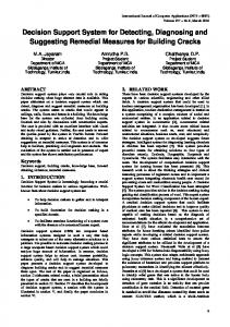
The Impulse adaptable memory system expands the traditional virtual memory hierarchy by adding address translation hardware to the main memory controller (MMC) [2, 11, 14]. Impulse uses physical addresses unused in conventional systems as remapped aliases of real physical addresses. For instance, in a system with 32-bit physical addresses and one gigabyte of installed DRAM, the physical addresses inside [0x40000000 – 0xFFFFFFFF] normally would be considered invalid. 1 Those, otherwise unused, physical addresses refer to a shadow address space. Figure 1 shows how addresses are mapped in an Impulse system. The real physical address space is directly backed up by physical memory; its size is exactly the size of installed physical memory. The shadow address space does not directly point to any real physical memory (thus the term shadow) and must be remapped to real physical addresses through the Impulse MMC. How the MMC interprets shadow addresses presented to it is configured by the operating system. This virtualization of unused physical addresses can provide different views of data stored in physical memory to programs. For example, it can create cache1
It is common to have I/O devices mapped to special “high” addresses. This problem can be easily avoided by not letting shadow address space overlap with I/O devices addresses.
Lixin Zhang et al. Virtual Space
MMU/TLB
Physical Space
Physical Memory
MMC
4
Real physical addresses Shadow addresses
Fig. 1. Address mapping in an Impulse system.
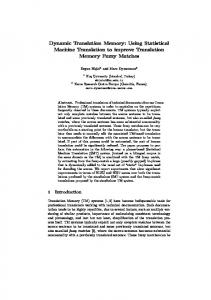
friendly data structures to improve the efficiency of the processor caches. The operating system manages all of the resources in the expanded memory hierarchy and provides an interface for the application to specify optimizations for particular data structures. The programmer (or the compiler) inserts appropriate system calls into the application code to configure the memory controller. To map a data item in the shadow address space to the physical memory, the Impulse MMC must first recover its virtual address. To avoid directly handling virtual addresses at the MMC, we require that the virtual address must be located inside a special virtual region. The OS creates a dense, flat page table in contiguous physical addresses for the special virtual region. We call the page table the memory controller page table. The OS then pins down this page table in main memory and sends its starting physical address to the memory controller so that the MMC can access this page table without interrupting the OS. Since data items in a shadow region are mapped to a special virtual region, the MMC only need compute offsets relative to the starting address of the virtual region. We call such an offset a pseudo-virtual address. For each shadow data item, the MMC first computes its pseudo-virtual address, then uses the memory controller page table to determine the data item’s real physical address. To speed up the translation from pseudo-virtual to physical addresses, the MMC uses an TLB to store recently used translations. We call this TLB the MTLB. Figure 2 shows a simplified block diagram of the Impulse memory system. The critical component of the Impulse MMC is the shadow engine, which processes all shadow accesses. The shadow engine contains a small scatter/gather SRAM buffer used as a place to scatter/gather cache lines in the shadow address space, some control registers to store remapping configuration information, an ALU unit (AddrCalc) to translate shadow addresses to pseudo-virtual addresses, and a Memory Controller Translation Lookaside Buffer (MTLB) to cache recently used translations from pseudo-virtual addresses to physical addresses. The control registers are split into eight different sets and are capable of saving configuration information for eight different mappings. However, all mappings share the same ALU unit and the same MTLB.
Dynamic Cache Line Assembly
MMU
L1
Shadow Address
Normal Address
CPU
system memory bus
?
Shadow engine Registers Buffer
MMC
5
AddrCalc
MTLB
L2
DRAM Interface
DRAM
DRAM
Fig. 2. Impulse architecture.
4
Design
The proposed dynamic cache line assembly mechanism is an extension of Impulse’s scatter/gather through an indirection vector remapping mechanism. Its main goal is to enable applications to access data spread through memory as if it were stored sequentially. In this section, we first talk about scatter/gather through an indirection vector, then describe the design of dynamic cache line assembly. 4.1
Scatter/Gather through An Indirection Vector
The Impulse system supports a remapping called scatter/gather through an indirection vector. For simplicity, we refer to it as IV remapping throughout the rest of this paper. IV remapping maps a region of shadow addresses to a data structure such that a shadow address at offset soffset in the shadow region is mapped to data item addressed by vector[soffset] in the physical memory. Figure 3 shows an example of using IV remapping on a sparse matrix-vector product algorithm. In this example, Pi is an alias array in the shadow address space. An element Pi[j] of this array is mapped to element P[ColIdx[j]] in the physical memory by the Impulse memory controller. For a shadow cache line containing elements Pi[j], Pi[j+1], . . . , Pi[j+k], the MMC fetches elements P[ColIdx[j]], P[ColIdx[j+1]], . . . , P[ColIdx[j+k]] one by one from the physical memory and packs them into a dense cache line. Figure 4 illustrates the gathering procedure. The shadow engine contains a one cache line SRAM buffer to store indirection vectors. We call this SRAM buffer the IV buffer. When the MMC receives a request for a cache line of Pi[], it loads the corresponding cache line of ColIdx[] into the IV buffer, if the IV buffer
6
Lixin Zhang et al. Pi = AMS_remap(P, ColIdx, n, ...); for (i = 0; i < n; i++) { sum = 0; for (j = Rows[i]; j < Rows[i+1]; j++) sum += Data[j] * P[ColIdx[j]]; b[i] = sum; }
for (i = 0; i < n; i++) { sum = 0; for (j = Rows[i]; j < Rows[i+1]; j++) sum += Data[j] * Pi[j]; b[i] = sum; }
Original code
After remapping
Fig. 3. Scatter/gather through an indirection vector changes indirect accesses to sequential accesses.
IV buffer
System Bus
Shadow engine
Cache
Physical Memory
AddrCalc MTLB
Scatter/gather buf Fig. 4. Visualize the gathering procedure through an indirection vector.
does not already contain it. The MMC then can interpret one element of the indirection vector per cycle. The indirection vector may store virtual addresses, array indices, or even real physical addresses. What it stores (addresses or indices) is specified when the remapping is configured; without loss of generality, we will refer to the contents of the IV buffer generically as “addresses” throughout the rest of this paper. If the IV buffer stores virtual address or array indices, the MMC passes each entry to the AddrCalc unit to generate a pseudo-virtual address and translates the pseudo-virtual address to a physical address using the MTLB. Once the MMC has a physical address for a data element, it uses this address to access physical memory. When a data item returns, it is packed into a dense cache line in the scatter/gather buffer. By mapping sparse, indirectly addressed data items into packed cache lines, scatter/gather through an indirection vector enables applications to replace indirect accesses with sequential accesses. As a result, applications reduce their bus bandwidth consumption, the cache footprint of their data, and the number of memory loads they must issue. A naive implementation of IV remapping requires that the indirection vector exists in the program and its number of elements be the same as the number of data items being gathered, e.g., Rows[n] in Figure 3. We extend IV remapping to implement dynamic cache line assembly, which can be used by programs where no indirection vector exists naturally and where the size of an indirection vector need not be equal to the number of data items being gathered.
Dynamic Cache Line Assembly
4.2
7
Dynamic Cache Line Assembly
The basic idea of dynamic cache line assembly is to create indirection vectors dynamically during program execution and to access them using Impulse’s IV remapping mechanism. The indirection vectors typically are small, usually smaller than a page. We choose small indirection vectors because accessing them and the resulting small alias arrays leaves a very small footprint in the cache. The small indirection vectors and alias arrays can be reused to remap large data structures. To use DCA, the application performs a system call to allocate two special ranges of shadow addresses and have the operating system map new virtual addresses to these two ranges. The first range is used to store the addresses from which the application wishes to load data (we call this the address region), while the second range is used to store the requested data (we call this the data region). The number of addresses that can be stored in the address region is the same as the number of data items that can be stored in the data region. There is a one-to-one mapping between elements of the two ranges: the ith element of the address region is the address of the ith element of the data region. The operating system also allocates a contiguous real physical memory to back up the address region in case an indirection vector is forced out of the IV buffer before the MMC has finished using it. After setting up the regions, the operating system informs the MMC of their location, as well as the size of each address and the size of the object that needs to be loaded from each address. For simplicity, we currently require that both the address and data regions are a multiple of a cache line size, and that the data objects are a power of two bytes. After setup, the application can exploit dynamic cache line assembly by filling a cache line in the address region with a set of addresses and writing it back to memory through a cache flush operation. When the MMC sees and recognizes this write-back, it stores the write-back cache line into both the IV buffer and the memory. Storing the write-back into the memory is necessary because the IV buffer may be used by another writeback. When the MMC receives a load request for a cache line in the data region, it checks to see if the IV buffer contains the corresponding cache line in the address region. If the required cache line is not in the IV buffer, the shadow engine loads it from memory. The MMC then interprets the contents of the IV buffer as a set of addresses, passes these addresses through the AddrCalc unit and the MTLB to generate the corresponding physical addresses, fetches data from these physical addresses, and stores the fetched data densely into the scatter/gather buffer inside the shadow engine. After an entire cache line has been packed, the MMC supplies it to the system bus from the scatter/gather buffer. Figure 5 shows how dynamic cache line assembly can be used to improve the performance of the random access loop presented in Section 1. In this example, we assume that L2 cache lines are 128 bytes, so each cache line can hold 32
8
Lixin Zhang et al.
float *aliasarray; int *idxvector; /* aliasarray[i]