Aug 13, 2013 - [1] D. Geer, "Chip makers turn to multicore processors," Computer, vol. 38, pp. 11-13 .... programming: Addison-Wesley Professional, 2010.
METASCALABLE HYBRID MESSAGE-PASSING AND MULTITHREADING ALGORITHMS FOR N-TUPLE COMPUTATION
by Manaschai Kunaseth
A Dissertation Presented to the FACULTY OF THE USC GRADUATE SCHOOL UNIVERSITY OF SOUTHERN CALIFORNIA In Partial Fulfillment of the Requirements for the Degree DOCTOR OF PHILOSOPHY (COMPUTER SCIENCE)
August 13th, 2013
© 2013
Manaschai Kunaseth
Abstract The emergence of the multicore era has granted unprecedented computing capabilities. Extensively available multicore clusters have influenced hybrid message-passing and multithreading parallel algorithms to become a standard parallelization for modern clusters. However, hybrid parallel applications of portable scalability on emerging high-end multicore clusters consisting of multimillion cores are yet to be accomplished. Achieving scalability on emerging multicore platforms is an enormous challenge, since we do not even know the architecture of future platforms, with new hardware features such as hardware transactional memory (HTM) constantly being deployed. Scalable implementation of molecular dynamics (MD) simulations on massively parallel computers has been one of the major driving forces of supercomputing technologies. Especially, recent advancements in reactive MD simulations based on many-body interatomic potentials have necessitated efficient dynamic n-tuple computation. Hence, it is of great significance now to develop scalable hybrid n-tuple computation algorithms to provide a viable foundation for high-performance parallel-computing software on forthcoming architectures. This dissertation research develops a scalable hybrid message-passing and multithreading algorithm for n-tuple MD simulation, which will continue to scale on future architectures (i.e. achieving metascalability). The two major goals of this dissertation research are: (1) design a scalable hybrid message-passing and multithreading parallel algorithmic framework on multicore architectures and evaluate it on most advanced parallel architectures; and (2) develop a
ii
computation-pattern algebraic framework to design scalable algorithms for general n-tuple computation and prove its optimality in a systematic and mathematically rigorous manner. To achieve the first goal, we have developed and thoroughly analyzed algorithms for hybrid message passing interface (MPI) + open multiprocessing (OpenMP) parallelization of ntuple MD simulation, which are scalable on large multicore clusters. Two data-privatization thread scheduling algorithms via nucleation-growth allocation have been designed: (1) compactvolume allocation scheduling (CVAS); and (2) breadth-first allocation scheduling (BFAS). These two algorithms combine fine-grain dynamic load balancing and minimal memoryfootprint threading. Theoretical study has revealed decent asymptotic memory efficiency for both algorithms, thereby reducing 75% memory consumption compared to a naïve-threading algorithm. Furthermore, performance benchmarks have confirmed higher performance of the hybrid MD algorithm over a traditional algorithm on large multicore clusters, where 2.58-fold speedup of the hybrid algorithm over the traditional algorithm was observed on 32,768 nodes of IBM BlueGene/P. We have also investigated the performance characteristics of HTM on the IBM BlueGene/Q computer in comparison with conventional concurrency control mechanisms, using an MD application as an example. Benchmark tests, along with overhead-cost and scalability analysis, have quantified relative performance advantages of HTM over other mechanisms. We found that the bookkeeping cost of HTM is high but that the rollback cost is low. We have proposed transaction fusion and spatially compact scheduling techniques to reduce the overhead of HTM with minimal programming. A strong scalability benchmark has shown that the fused HTM has the shortest runtime among various concurrency control mechanisms without extra
iii
memory. Based on the performance characterization, we have derived a decision tree in the concurrency-control design space for general multithreading applications. To achieve the second goal, we have developed a computation-pattern algebraic framework
to
mathematically
formulate
general
n-tuple
computation.
Based
on
translation/reflection-invariant properties of computation patterns within this framework, we have designed a shift-collapse (SC) algorithm for cell-based parallel MD. Theoretical analysis has quantified the compact n-tuple search space and small communication cost of SC-MD for arbitrary n, which are reduced to those in best pair-computation approaches (e.g. eighth-shell method) for n = 2. Benchmark tests have shown that SC-MD outperforms our production MD code at the finest grain, with 9.7- and 5.1-fold speedups on Intel-Xeon and BlueGene/Q clusters. SC-MD has also exhibited excellent strong scalability. In addition, we have analyzed the computational and data-access patterns of MD, which led to the development of a performance prediction model for short-range pair-wise force computations in MD simulations. The analysis and performance model provide fundamental understanding of computation patterns and optimality of certain parameters in MD simulations, thus allowing scientists to determine the optimal cell dimension in a linked-list cell method. The model has accurately estimated the number of operations during the simulations with the maximum error of 10.6% compared to actual measurements. Analysis and benchmark of the model have revealed that the optimal cell dimension minimizing the computation time is determined by a trade-off between decreasing search space and increasing linked-list cell access for smaller cells. One difficulty about MD is that it is a dynamic irregular application, which often suffers considerable performance deterioration during execution. To address this problem, an optimal iv
data-reordering schedule has been developed for runtime memory-access optimization of MD simulations on parallel computers. Analysis of the memory-access penalty during MD simulations has shown that the performance improvement from computation and data reordering degrades gradually as data translation lookaside buffer misses increase. We have also found correlations between the performance degradation with physical properties such as the simulated temperature, as well as with computational parameters such as the spatial-decomposition granularity. Based on a performance model and pre-profiling of data fragmentation behaviors, we have developed an optimal runtime data-reordering schedule, thereby archiving speedup of 1.35, 1.36 and 1.28, respectively, for MD simulations of silica at temperatures 300 K, 3,000 K and 6,000 K. The main contributions of this dissertation research are two-fold: Metascalable hybrid message-passing and multithreading parallel algorithmic framework on emerging multicore parallel clusters, and a novel computation-pattern algebraic framework to design scalable algorithm for general n-tuple computation and prove its optimality in a mathematically rigorous manner. We expect that the proposed hybrid algorithms and mathematical approaches will provide a generic framework to a broad range of applications on future extreme-scale computing platforms.
v
Table of Contents CHAPTER 1 INTRODUCTION .................................................................................................................................1! 1.1! MOTIVATIONS ...................................................................................................................................................1! 1.2! CHALLENGES AND GOALS .................................................................................................................................2! 1.3! BACKGROUND ...................................................................................................................................................3! 1.3.1! Molecular Dynamics Simulation ..............................................................................................................4! 1.3.2! Multicore Architectures ............................................................................................................................4! 1.3.3! Hybrid Parallelization ..............................................................................................................................6! 1.3.4! n-Tuple Molecular Dynamics ...................................................................................................................8! 1.3.5! Recent Development of Parallel MD Algorithms .....................................................................................8! 1.4! CONTRIBUTIONS................................................................................................................................................9! 1.5! STRUCTURE OF THIS DISSERTATION ...............................................................................................................12! CHAPTER 2 HYBRID MESSAGE-PASSING AND MULTITHREADING PARALLELIZATION ...............13! 2.1! INTRODUCTION ...............................................................................................................................................13! 2.2! DOMAIN DECOMPOSITION MOLECULAR DYNAMICS .......................................................................................14! 2.2.1! Internode Operations..............................................................................................................................15! 2.2.2! Intranode Operations .............................................................................................................................16! 2.2.3! Hybrid MPI/OpenMP Parallelization ....................................................................................................18! 2.3! DATA PRIVATIZATION SCHEDULING ALGORITHM ..........................................................................................20! 2.3.1! Naïve Data Privatization Threading Algorithm .....................................................................................20! 2.3.2! Nucleation-Growth Allocation Algorithm ..............................................................................................21! 2.4! THEORETICAL ANALYSIS ................................................................................................................................26! 2.4.1! Load Imbalance Analysis .......................................................................................................................26! 2.4.2! Memory Consumption Analysis ..............................................................................................................27! 2.4.3! Computation Complexity Analysis .........................................................................................................35!
vi
2.5! PERFORMANCE EVALUATION ..........................................................................................................................37! 2.5.1! Scheduling Cost ......................................................................................................................................37! 2.5.2! Thread-Level Load Balancing ................................................................................................................38! 2.5.3! Memory Consumption ............................................................................................................................39! 2.5.4! Reduction-Sum Operation Cost ..............................................................................................................40! 2.5.5! Strong-Scaling Benchmark .....................................................................................................................41! 2.6! SUMMARY .......................................................................................................................................................44! CHAPTER 3 PERFORMANCE CHARACTERISTICS OF CONCURRENCY CONTROL MECHANISMS .......................................................................................................................................................................................45! 3.1! INTRODUCTION ...............................................................................................................................................46! 3.2! BACKGROUND .................................................................................................................................................47! 3.2.1! Hybrid MPI/OpenMP Molecular Dynamics ..........................................................................................47! 3.2.2! Race Conditions and Traditional Concurrency Control Mechanisms ...................................................49! 3.2.3! Hardware Transactional Memory on BlueGene/Q ................................................................................50! 3.3! PERFORMANCE CHARACTERIZATION OF CONCURRENCY CONTROL MECHANISMS ........................................53! 3.3.1! Concurrency-Control Cost Modeling .....................................................................................................53! 3.3.2! Model Parameter Fitting Using Microbenchmark .................................................................................55! 3.4! MOLECULAR DYNAMICS BENCHMARK ...........................................................................................................57! 3.4.1! Performance Comparison of Concurrency Controls .............................................................................60! 3.4.2! Rollback Penalty .....................................................................................................................................64! 3.4.3! Effect of Scheduling Algorithms on Rollback .........................................................................................65! 3.5! DESIGN SPACE FOR CONCURRENCY CONTROLS ..............................................................................................69! 3.6! CONCLUSION AND DISCUSSION .......................................................................................................................74! CHAPTER 4 EMBEDDED PERFORMANCE PREDICTION MODEL .............................................................75! 4.1! EMBEDDED PERFORMANCE PREDICTION MODEL .............................................................................................76! 4.1.1! Grand Scheme of the Embedded Performance Prediction Model..........................................................79! 4.1.2! Tailored Scheme of the Embedded Performance Prediction Model For Molecular Dynamics.............80!
vii
4.1.3! Model Validation ....................................................................................................................................82! 4.2! OPTIMAL PARALLELIZATION PREDICTION VIA PERFORMANCE MODEL ..........................................................83! 4.2.1! Performance Model Design Principles ..................................................................................................84! 4.2.2! Model Fitting and Validation .................................................................................................................87! 4.3! SUMMARY .......................................................................................................................................................89! CHAPTER 5 N-TUPLE COMPUTATION FORMALISM AND SOLUTION FOR RANGED-LIMITED MANY-BODY MOLECULAR DYNAMICS ...........................................................................................................91! 5.1! PROBLEM STATEMENT ....................................................................................................................................92! 5.2! BACKGROUND .................................................................................................................................................92! 5.2.1! Many-Body Molecular Dynamics ...........................................................................................................92! 5.2.2! Dynamic Range-Limited n-Tuple Computation......................................................................................94! 5.3! COMPUTATION-PATTERN ALGEBRAIC FRAMEWORK ......................................................................................95! 5.3.1! Algebraic Formulation of Cell-Based MD .............................................................................................96! 5.3.2! Shift-Collapse Algorithm ......................................................................................................................103! 5.3.3! Correctness of SC Algorithm ................................................................................................................107! 5.4! THEORETICAL ANALYSIS ..............................................................................................................................111! 5.4.1! Search-Cost Analysis of SC Pattern .....................................................................................................111! 5.4.2! Communication Analysis of SC Pattern ...............................................................................................116! 5.4.3! Relation to Previous Works ..................................................................................................................117! 5.5! PERFORMANCE BENCHMARK ........................................................................................................................119! 5.5.1! Search Cost of SC and FS Algorithms ..................................................................................................120! 5.5.2! Fine-Grain Parallelism ........................................................................................................................121! 5.5.3! Strong-Scaling Benchmark ...................................................................................................................124! 5.6! CONCLUSION .................................................................................................................................................125! CHAPTER 6 PERFORMANCE ANALYSIS, MODELING, AND OPTIMIZATION OF CELL-BASED MOLECULAR DYNAMICS ...................................................................................................................................127! 6.1! INTRODUCTION .............................................................................................................................................128!
viii
6.2! CELL-BASE MOLECULAR DYNAMICS SIMULATIONS.....................................................................................129! 6.3! PERFORMANCE ANALYSIS .............................................................................................................................131! 6.3.1! Short-Range Interaction Cost Model of the Conventional Linked-List Cell Method ...........................132! 6.3.2! Short-Range Interaction Cost Model of the Reduced Linked-list Cell Method ....................................135! 6.4! MODEL VALIDATION.....................................................................................................................................138! 6.4.1! Validation of the Operation Counts Model ..........................................................................................138! 6.4.2! Parameter Fitting .................................................................................................................................140! 6.5! PERFORMANCE RESULTS ...............................................................................................................................141! 6.6! SUMMARY .....................................................................................................................................................145! CHAPTER 7 MEMORY-ACCESS ANALYSIS AND OPTIMIZATION VIA DYNAMIC DATA REORDERING .........................................................................................................................................................146! 7.1! INTRODUCTION .............................................................................................................................................147! 7.2! DATA FRAGMENTATION IN PARALLEL MOLECULAR DYNAMICS ..................................................................148! 7.2.1! Temperature Induced Fragmentation...................................................................................................150! 7.2.2! Granularity Induced Fragmentation ....................................................................................................155! 7.3! PERFORMANCE MEASUREMENT ....................................................................................................................158! 7.4! REORDERING FREQUENCY OPTIMIZATION ....................................................................................................163! 7.5! SUMMARY .....................................................................................................................................................166! CHAPTER 8 CONCLUSIONS ................................................................................................................................168! REFERENCES ..........................................................................................................................................................171!
ix
List of Tables Table 3.1: Specification of BlueGene/Q at LLNL. ....................................................................... 52! Table 3.2: Parallel efficiency estimate resulting from the decision tree ....................................... 73! Table 4.1: Benchmark cluster specifications ................................................................................ 82! Table 4.2: Parameter-fitting result of MPI-only and hybrid models using bi-square regression . 87! Table 5.1: Specifications of testing platforms. ........................................................................... 120! Table 6.1: Asymptotic complexity of parameter Ps", Pc", and Pl" over µ. ................................... 138! Table 6.2: Accuracy of the operation counts model. .................................................................. 139! Table 6.3: Estimated operation costs from various regression algorithms. ................................ 141! Table 6.4: The predicted versus measured values of the optimal µ with their corresponding speedup compared to the case of no cell dimension reduction. .................................................. 144! Table 7.1: 3,000 K silica datasets with varying granularities: The number of linked-list cells, the portion of surface cells, and the surface-to-volume ratio of the spatial subsystem are listed for each dataset. ................................................................................................................................ 157! Table 7.2: Runtime result with different ordering methods for silica systems at temperature 300K............................................................................................................................................ 162! Table 7.3: 3,000 K silica datasets varying granularities ............................................................. 164!
x
List of Figures Figure 2.1: (a) 2D schematic of the linked-list cell method for pair computation with the cell dimension rc. Only forces exerted by particles within the cutoff radius (represented by a two-headed arrow) are computed for particle i. The blue particles represent particles in the top-half neighbor cells where the force is computed directly, while the gray particles is a particle whose force is computed via reaction force. (b) 2D schematic of a single computation unit λk. The shaded cells Cj pointed by the arrows constitute the half neighbor cells, nn+(Ck). ........................................................................................................................ 18! Figure 2.2: Schematic workflow of a hybrid MPI/OpenMP scheme. The master thread schedules works for the worker threads before entering the parallel threading section. The master thread also handles internode communication, which is explicitly performed outside the threading region. ................................................................................................................... 19! Figure 2.3: Schematic of a memory layout for a naïve data privatization. To avoid data race condition among threads, the entire output array is locally duplicated for each thread. These local arrays are privatized on the thread memory space and thus eliminate race condition during the computation phase. This approach also incurs additional reduction operations to sum all local results to the global array. ............................................................................... 21! Figure 2.4: Memory layout and three-step algorithm for nucleation-growth allocation algorithm. Worker threads only allocate the essential portion of the force arrays, corresponding to their assigned workload................................................................................................................. 22! Figure 2.5: Thread load-balancing algorithm. .............................................................................. 24!
xi
Figure 2.6: Pseudocode of compact-volume allocation scheduling algorithm. ............................ 24! Figure 2.7: Pseudocode of breadth-first allocation scheduling algorithm. ................................... 26! Figure 2.8: Geometric effects on surface-to-volume ratio. (a) and (b) show the surface volume (shell area) of cubic and spherical shapes with the same main volume. (c) and (d) show the discretized version, which indicates that the spherical shape consumes less volume than the cubic shape. The square grid represents cells in which particles reside. The blue area refers to the main volume while the red area shows the surface volume. Variable l is defined as the side length of main volume created by BFAS while r denotes the radius of CVAS. The surface thickness is rc. ........................................................................................................... 29! Figure 2.9: Illustrates a lower-bound memory consumption estimation of CVAS and BFAS algorithms. The graph indicates that CVAS consumes less memory than BFAS. ............... 34! Figure 2.10: Scheduling cost for CVAS and BFAS algorithms for 128,000-particle system on 64 BG/P nodes. The circles and squares are average scheduling times of CVAS and BFAS algorithms, respectively. ....................................................................................................... 38! Figure 2.11: Illustrates the load-imbalance factor γ of CVAS as a function of p from theoretical bound, scheduler estimation, and actual measurement. ........................................................ 39! Figure 2.12: Presents average memory consumption for the private force arrays as a function of p using CVAS compared to the naïve method. Numbers in the legend denote n. ................... 40! Figure 2.13: Shows average reduction-sum operation time of the CVAS as a function of p. Numbers in the legend denote n............................................................................................ 41! Figure 2.14: (a) Thread-level strong scalability of the parallel section on a four quad-core AMD Opteron 2.3 GHz with fixed problem size at n = 8,192 particles. (b) Total running time per
xii
MD steps of 1,024 – 32,768 Power PC 450 850 MHz cores on BG/P for a fixed problem size at N = 0.84-million particles and (c) 1.68-million particles. ......................................... 43! Figure 3.1: The benchmark kernel of a serial code without concurrency control. ....................... 56! Figure 3.2: The benchmark kernel with HTM control over 4 updates. ........................................ 56! Figure 3.3: The benchmark kernel with HTM control over 4 updates. ........................................ 57! Figure 3.4: Code fragment from the force update routine in ddcMD code, which has potential memory conflicts. ................................................................................................................. 59! Figure 3.5: (a) Strong-scaling runtime of ddcMD comparing the performance of concurrency control mechanisms. (b) Runtime overhead of each concurrency controls normalized by the baseline runtime. ................................................................................................................... 63! Figure 3.6: Impact of rollback on runtime, indicating linear correlation between runtime overhead and rollback ratio. .................................................................................................. 65! Figure 3.7: Workload distribution in a physical space, where cells assigned to different threads are distinguished by different colors. (a) Random scheduling; and (b) Spatially-compact scheduling. ............................................................................................................................ 67! Figure 3.8: Rollback ratio (a) and the runtime overhead (b) as a function of the number of threads for the three scheduling algorithms....................................................................................... 68! Figure 3.9: Typical program structure of loop-oriented applications ........................................... 70! Figure 3.10: Decision tree for concurrency-control design space. We should note that OMPcritical at the bottom has very high performance penalty. .................................................... 72! Figure 3.11: Analysis of four concurrency control mechanisms. Circles and triangles denote strong and weak advantages, respectively, while crosses denote disadvantage. .................. 73!
xiii
Figure 4.1: Illustrates hierarchy architecture of a modern high-end machine. Combinations of distributed and shared memory parallelism are used in each architecture level. .................. 78! Figure 4.2: Optimal region of MPI-only versus hybrid MPI/OpenMP implementations. The crossover line expected to remain constant at N/P. .............................................................. 84! Figure 4.3: Validation of (a) MPI-only and (b) hybrid MPI/OpenMP performance models. Blue lines denote the model results while the red dots denote the actual measurement on BlueGene/P. .......................................................................................................................... 88! Figure 4.4: The performance model predictions of 1.6 million-particle system of MPI-only versus hybrid MPI/OpenMP implementations, indicating the same result as in terms of optimality region as the actual measurements. ..................................................................... 89! Figure 4.5: Extrapolation of the prediction models, fixing granularity per core constant. The predicted model suggested that the crossover is moved up to ~ 200 – 400 particles/core. .. 89! Figure 5.1: Schematic of range-limited n-tuples: (a) pair (n = 2), (b) triplet (n = 3), and (c) quadruplet (n = 4). ................................................................................................................ 94! Figure 5.2: Set diagram showing the relationship of a bounding force set S(n) with Γ(n) and Γ*(n) 95! Figure 5.3: (a) Cell data-structure, where circles are atoms and small squares are cells. Dashed circle denotes the cutoff radius centered at atom i. (b) Uniform-cell pattern for pair computation, which generates all pairs between each cell and its neighbor cells. ............... 97! Figure 5.4: n-tuple (n = 3) generation for cell search-space Scell of cell c(q) (colored in magenta) and computation path (v0,v1,v2). Scell generates all triplets where the 1st, 2nd, and 3rd atoms in the triplet are in cells c(q+v0), c(q+v1), and c(q+v2), respectively. Dashed line shows one of the triplets (ri,rj,rk)................................................................................................................ 100! Figure 5.5: Uniform-cell pattern MD algorithm. ........................................................................ 101!
xiv
Figure 5.6: 2D schematic of a shift-collapse (SC) computation pattern. (a) FS computation pattern for n = 3, containing all possible paths of length 3 originated from the center cell (magenta). (b) SC computation pattern after OC-shift and R-collapse subroutines. Yellow cells denote the cell coverage of the center cell, which for SC is much smaller than that for FS. ....................................................................................................................................... 105! Figure 5.7: Shift-Collapse algorithm. ......................................................................................... 105! Figure 5.8: FS generation algorithm. .......................................................................................... 106! Figure 5.9: OC-shift algorithm. .................................................................................................. 106! Figure 5.10: Reflective-collapse algorithm................................................................................. 107! Figure 5.11: Schematic of shell methods for pair computation: (a) full-shell, (b) half-shell, and (c) eighth-shell patterns....................................................................................................... 119! Figure 5.12: Average number of triplets as a function of domain size. Error bars are too small to be visible in the plot. ........................................................................................................... 121! Figure 5.13: Runtime of SC-MD (red), FS-MD (green), and Hybrid-MD (blue) as a function of the granularity on (a) 48 Intel Xeon nodes and (b) 64 BlueGene/Q nodes. The plot shows that SC-MD is the fastest for N/P < 2,095 and 425 on Intel Xeon and BlueGene/Q platforms, respectively. ....................................................................................................... 123! Figure 5.14: Strong scaling speedup of SC-MD, Hybrid-MD, and FS-MD on (a) Intel Xeon cluster and (b) BlueGene/Q. ............................................................................................... 125! Figure 6.1: 2D schematic of the linked-list cell method. (a) Illustration of conventional linkedlist cell method with cell dimension Rs ≥ Rc. (b) 2D schematic of the reduced linked-list cell method. Atoms in the shaded region will be excluded from the force computation of
xv
center atom i. Only forces exerted by atoms within the cutoff radius (represented by a twoheaded arrow) are computed. .............................................................................................. 129! Figure 6.2: Force computation algorithm. .................................................................................. 130! Figure 6.3: The running time from the prediction and the measurement for Rc = 10 Å. The numerals are the number of atoms. ..................................................................................... 143! Figure 6.4: Comparison of speedup gained from predicted and actual μ* for Rc = 6.6 and 10 Å. ............................................................................................................................................. 143! Figure 7.1: Schematic of memory layout for atom data in (a) a fully disordered state and (b) a fully ordered state, where C(i,j,k) is the linked list for the cell with indices i, j, and k in the x, y, and z directions, respectively, r[a] is the data associated with the a-th atom. ............ 149! Figure 7.2: Time variation of data fragmentation ratio over 3,000 MD steps. Three datasets of different initial temperatures (300 K, 3,000 K, and 6,000 K) are plotted. .......................... 152! Figure 7.3: Mean squared displacement (MSD) of 300 K, 3,000 K, and 6,000 K datasets. The MSD of 300 K dataset remains constant at 0.23 Å2 (too small to be seen in the figure). The inset shows the diffusion coefficients at the three temperatures......................................... 153! Figure 7.4: Data fragmentation ratio during aluminum combustion simulation over 2,000 MD steps. The dataset involves 15 million atoms on 1,024 processors. .................................... 154! Figure 7.5: (a) Time variation of the data fragmentation ratio of 12,288-atom silica at 3,000 K over 3,000 MD steps, for surface cells, core cells, and both combined. (b) Time variation of the data fragmentation ratio of 3,000 K silica with varying granularities over 3,000 MD steps..................................................................................................................................... 156! Figure 7.6: Time variation of the DTLB miss rate in 300 K, 3,000 K and 6,000 K dataset over 3000 MD steps. ................................................................................................................... 159!
xvi
Figure 7.7: Relation between the DTLB miss rate and the data fragmentation ratio in 300 K, 3,000 K and 6,000 K datasets. ............................................................................................ 160! Figure 7.8: Running time per MD step as a function of MD steps at temperatures 300K, 3,000K, and 6,000K for 98,304 silica atoms. ................................................................................... 161! Figure 7.9: Schematic ordering of (a) sequential ordering (b) 3rd-order 2D Hilbert-curve ordering (c) 3rd-order 2D Morton-curve ordering. ............................................................................. 163! Figure 7.10: Total running time after 3,000 MD steps as a function of reordering periods. The optimal period for 300 K, 3,000 K and 6,000 K datasets are 69, 5 and 3 steps, respectively. ............................................................................................................................................. 165! Figure 7.11: Comparison of total running time of silica MD over 3,000 steps achieved by model prediction and actual measurement of periodic reordering compared with that of the original code without ordering. (All tests are conducted with 98,304 atoms per core.) .................. 166!
xvii
Chapter 1
Introduction
1.1 Motivations Computer simulation has become vital tools to solve a broad range of scientific and engineering problems such as studying properties of nanomaterials at the atomistic scale, designing efficient wind-turbine farms for high-yield clean energy production, simulating catastrophic earthquakes for disaster preparedness, and modeling drug for curing fatal diseases. However, larger and longer simulations, along with sophisticated modeling of real-world problems, are required in order to characterize realistic systems. One simulation model of great significance is molecular dynamics (MD) simulation, which has broad applications in diverse fields such as physics, chemistry, biology, and materials science. Recent advancements in chemically reactive MD simulations have driven the need of vast computing power. Thanks to the advent of multicore architectures, the rapid increase in computing power has enabled scientists to confront these grand challenges for mankind.
1
Nevertheless, efficiently harvesting computing power from the modern architectures is challenging for application developers due to the sophisticated structure of computing platforms. Research has focused on evolving legacy MD algorithms to efficiently execute on modern architectures. Especially, recent advancements in reactive MD simulations based on many-body interatomic potentials have necessitated efficient dynamic n-tuple computation. An aspiration to have scalable and efficient parallel frameworks along with systematic understanding of the reactive MD problems has motivated us to find solutions to these challenges. This will enable software developers to continually enhance MD applications to cope with the advent of novel architectures in the future.
1.2 Challenges and Goals The emergence of the multicore era has granted unprecedented computing capabilities. However, the longstanding message-passing programming model tends to underutilize the full potential of modern architectures. This has posed difficulties to software developers since the legacy programs significantly relied on the increased processing power of a single processor instead of the increased number of cores [1-3]. Thus, many algorithms currently in use are not suitable for the shared-memory model, thereby demanding substantial alterations in software [4, 5]. Also, performance of the traditional concurrency techniques tends to be limited on a largescale concurrent system. Addressing these issues typically requires extensive coding effort, which limits wide use of massive shared-memory platforms. Hence it is of great challenge to develop a parallel algorithm that possesses “metascalability” (i.e., design once, continue to scale on future architectures) [6] for applications on continuously evolving platforms.
2
Despite remarkable progresses in parallel algorithms for simple MD, parallel dynamic ntuple computation of reactive MD is still in its infancy. The major challenge emerges from the lack of fundamental understanding of general n-tuple computation characteristics: How can we understand the fundamental characteristics of n-tuple computation such that we can apply the benefits from advanced techniques in simple MD into arbitrary dynamic n-tuple computations? To address these challenges, this dissertation develops a metascalable parallel algorithmic framework, along with mathematical formulations and optimal solutions for general n-tuple computation. This allows scientists to fully utilize the computational capacity of high-end multicore machines to solve n-tuple computation, encompassing even larger spatiotemporal barrier of the physical simulations on the current and forthcoming platforms.
1.3 Background In this section, we provide background information on our research. First, we introduce MD, a prototypical scientific application that is characterized by a number of complications toward parallelization on the multicore architecture. Second, We provide background information on emerging multicore architectures. Third, we discuss our hierarchical parallelization, specifically, a hybrid message-passing and multithreading algorithm for scientific applications without loss of generality. Next, we explain n-tuple computation in many-body MD, which is used to perform reactive MD simulation. Finally, we provide a description of state-ofthe-art scalable parallel MD algorithms.
3
1.3.1 Molecular Dynamics Simulation MD simulation has become an important tool [7] to study a broad range of scientific problems at the atomistic level [8-14]. MD simulation follows the phase-space trajectories of an N-particle system, where the forces between particles are given by the gradient of a potential energy function. Positions and velocities of all particles are updated at each MD step by numerically integrating coupled ordinary differential equations. The dominant computation of MD simulations is the evaluation of the potential energy function and associated forces. Many potential energy models were proposed in order to describe numerous properties of various materials. Some of these impose significant computational challenges [15-19]. Many methods exist to reduce this computational complexity [17-21]. Another example of important potential models is one consisting of many-body terms [16]. The dominant computation in such MD simulation is the evaluation of many-body terms involving summation over particle ntuples.
1.3.2 Multicore Architectures The rapid growth in computing power enables scientists to address more challenging problems by using high-end supercomputers [22, 23]. However, recent improvements in computing power are now gained using multicore architectures instead of increased clock speed [2, 24]. Application scientists at the forefront of high-performance computing (HPC) have been investigating the use of hybrid architectures to improve performance of scientific codes. Hierarchical architectures attempt to improve application performance by combining conventional processors with any of a variety of more specialized processors such as graphics processing units (GPUs) [25, 26], manycores [27-29], and Cells [30, 31]. This marks the end of 4
the free-ride era, where legacy applications cannot increase performance on a newer chip without substantial modification. Furthermore, the number of cores per chip is expected to grow continuously, which deepens the performance impact on the legacy software. Multicore processors with sophisticated computational and memory organizations have been developed as a result of the pursuit for high performance with low energy usage. At the low-level of memory hierarchy, most of the recent multicore chip designs adopt heterogeneous cache access at the cache level. This design has local level 1 and level 2 caches for individual core, while subsets of cores share its last-level cache (LLC). The cache-coherency concept is usually adopted, which guarantees data consistency among all cores in a node. At a node level, there are two major approaches for memory hierarchy: (1) symmetric multiprocessing (SMP), where all the compute cores have the same cost accessing memory; and (2) non-uniform memory access (NUMA), where each processors has different cost to access each memory module. NUMA paradigm requires more attention from software developers to maintain maximal performance [32, 33] (e.g. requires thread pinning to avoid thread switching between cores). However, SMP paradigm tends to have higher latency and is more difficult in circuit design. Nevertheless, the shared-memory concept is usually implemented on a multicore chip. This raises the issues of race conditions, and load balancing when multithreading is used. As multicore becomes the standard of modern supercomputers, two significant issues have emerged: (1) the performance of traditional parallel applications, which are solely based on message passing interface (MPI), is expected to degrade substantially [34]; and (2) the memory available per core tends to decline, since the growth of the number of cores per chip is considerably faster than that of the available memory. To address these complications, hierarchical parallelization frameworks, which integrate several parallel methods to provide 5
different levels of parallelism, have been proposed as a solution to this scalability problem on multicore platforms [6, 35-37]. In addition, a recent trend in HPC also focuses on heterogeneous computing. A combination of generic multicore chips and accelerators such as general-purpose graphics processing unit (GPGPU) [38-42] and manycore processor [43] (i.e. light-weight general processing component such as Intel Many Integrated Cores (MIC) chip) are used. Although accelerators are powerful for specific types of problems such as highly efficient floating-point operations in GPGPU, they usually do not execute every instruction efficiently, if it is able to run at all. Therefore, generic multicore chips are still needed to run non-specialized code sections in the program.
1.3.3 Hybrid Parallelization Hybrid parallelization is a parallelization approach that combines multiple parallelization techniques in order to achieve the best parallelization performance. Hybrid parallelization has been widely used for applications to execute on emerging multicore platforms, using a hybrid scheme reflecting the two-level hierarchical structural designs of multicore clusters. The most common
schemes
for
hybrid
parallelization
is
distributed
memory
for
inter-node
communications via message passing, and shared memory for intra-node communication via multithreading. At cluster-level, divide-and-conquer parallel algorithms based on spatial decomposition implemented with MPI are widely used, since MPI is the de-facto standard for high-end parallel computing for decades. MPI provides a moderate-transparency communication framework for parallel applications, by allowing software developers to explicitly code communication routines 6
from elementary communication building blocks without being concerned with sophisticated network protocols [44]. The basic communication functions provided by the MPI standard include synchronous/asynchronous end-to-end communications and collective communications, while secondary functions based on the basic functions are also provided. At node-level parallelization, multithreading is a common strategy to exploit the sharedmemory property of multicore chip. Numerous multithreading frameworks are widely available in computer science communities. In HPC area, multithreading frameworks generally equipped with modern compilers include POSIX thread (Pthread) [45] and Open Multiprocessing (OpenMP) [46]. Pthread provides most of the low-level operations with low overhead to the users with the cost of complicated coding. On the other hand, OpenMP offers simpler framework for multithreading but many operations cost considerable overhead. Variants of this message-passing/multithreading hybrid scheme have been proposed and studied broadly [37, 47-51]. Peng et al. [35] added one more step of parallelism at the data level through single-instruction multiple-data (SIMD) techniques, while recent studies [41, 52] have extended this scheme to cover GPGPU context. The hierarchical framework is expected to exploit data concurrency efficiently and continue to scale on future multicore platforms. Since most of the legacy software operates efficiently on supercomputers using MPI, the great challenge for the hybrid message-passing and multithreading parallelization lies on the multithreading part. The most typical issues associated with multithreading are race conditions and load balancing. Race condition is one of the common problems that plague program developers since the earliest age of computing. Although numerous methods were proposed to deal with race conditions (e.g. semaphores, critical section, transactional memory), the performance-sensitive nature of high-performance applications usually renders these naïve 7
methods impractical. On the other hand, load imbalance at the thread level usually occurs at finegrain scope, which requires that load balancers must be much more dynamic. Also, issues like context switching and false-sharing place tighter constrains on the design and usage of multithreading.
1.3.4 n-Tuple Molecular Dynamics MD simulation using a differentiable interatomic potential-energy function Φ was started by Rahman in 1964 [53] using a pair-wise potential energy, in which Φ is a sum of atomic-pair energies. Since then, scientists started performing many-body MD simulations that use n-tuple (n ≥ 3) energy functions for accurate description of a wider range of materials. In one type of ntuple computation (i.e. static n-tuple computation) used typically in biomolecular simulations [54], the list of atomic n-tuples is fixed throughout the simulation. In another (i.e. dynamic ntuple computation), n-tuple lists within given interaction ranges are constructed at every simulation time step [55, 56]. Recent advancements in chemically reactive MD simulations [57] have renewed interests in efficient implementation of dynamic n-tuple computation [58]. Reactive MD describes the formation and breakage of chemical bonds based on a reactive bondorder concept [57]. In the ReaxFF approach, for example, n is 4 explicitly, and force computation involves up to n = 6 due to chain-rule differentiations through bond-order terms [59-61].
1.3.5 Recent Development of Parallel MD Algorithms Scalable implementation of MD on massively parallel computers has been one of the major driving forces of supercomputing technologies [62-68]. Earlier parallel implementations of MD were based on spatial decomposition, in which the simulated physical volume is subdivided 8
into spatially localized sub-volumes that are assigned to different processors [69]. For long-range pair (n = 2) computation, octree-based O(N) algorithms (N is the number of atoms) [20] have highly scalable parallel implementations [70, 71]. For short-ranged (or range-limited) pair computation, Plimpton relaxed the conventional “owner-compute” rule (i.e., computation is performed by a processor that has data) to design a force-decomposition algorithm to increase the concurrency [72]. Since then, various hybrid spatial-force decomposition algorithms have been designed [73]. On distributed-memory parallel computers, atomic data needed for rangelimited pair computations are copied from neighbor processors. The most primitive scheme for these atom-caching operations is full shell (FS), in which data from 26 (face-, edge-, and cornersharing) neighbor sub-volumes are imported from other processors. In the half-shell (HS) scheme, Newton’s third law is utilized to halve the number of imported sub-volumes to 13 [69]. Relaxation of the owner-compute rule further reduces this number to 7 in the eighth-shell (ES) scheme [11]. In the case of special-purpose computers with low network latency, neutralterritory (NT) [74] and related [75] schemes achieve asymptotically smaller import volumes for fine granularities, N/P (P is the number of processors). In addition to these parallel algorithms for dynamic pair computations, numerous schemes have been employed in biological MD codes to efficiently compute static n-tuple computations [12, 73].
1.4 Contributions The main contributions of this dissertation research are two-fold: Metascalable hybrid message-passing and multithreading parallel algorithmic framework on emerging multicore parallel clusters, and a novel computation-pattern algebraic framework to design a scalable
9
algorithm for general n-tuple computation and prove its optimality in a mathematically rigorous manner. To design a metascalable algorithm, we have developed and thoroughly analyzed algorithms for hybrid MPI + OpenMP parallelization of n-tuple MD simulation, which are scalable on large multicore clusters. Two data-privatization thread scheduling algorithms via nucleation-growth allocation have been designed: (1) compact-volume allocation scheduling (CVAS); and (2) breadth-first allocation scheduling (BFAS). These two algorithms combine fine-grain dynamic load balancing and minimal memory-footprint threading. Theoretical study has revealed decent asymptotic memory efficiency for both algorithms, thereby reducing 75% memory consumption compared to a naïve-threading algorithm. Furthermore, performance benchmarks have confirmed higher performance of the hybrid MD algorithm over a traditional algorithm on large multicore clusters, where 2.58-fold speedup of the hybrid algorithm over the traditional algorithm was observed on 32,768 nodes of IBM BlueGene/P. To aid the multithreading program-design decision, we have investigated the performance characteristics of HTM on the IBM BlueGene/Q computer in comparison with conventional concurrency control mechanisms, using an MD application as an example. Benchmark tests, along with overhead-cost and scalability analysis, have quantified relative performance advantages of HTM over other mechanisms. We found that the bookkeeping cost of HTM is high but that the rollback cost is low. We have proposed transaction fusion and spatially compact scheduling techniques to reduce the overhead of HTM with minimal programming. A strong scalability benchmark has shown that the fused HTM has the shortest runtime among various concurrency control mechanisms without extra memory. Based on the performance
10
characterization, we have derived a decision tree in the concurrency-control design space for general multithreading applications. Regarding the second contribution, we have developed a computation-pattern algebraic framework
to
mathematically
formulate
general
n-tuple
computation.
Based
on
translation/reflection-invariant properties of computation patterns within this framework, we have designed a shift-collapse (SC) algorithm for cell-based parallel MD. Theoretical analysis has quantified the compact n-tuple search space and small communication cost of SC-MD for arbitrary n, which are reduced to those in best pair-computation approaches (e.g. eighth-shell method) for n = 2. Benchmark tests have shown that SC-MD outperforms our production MD code at the finest grain, with 9.7- and 5.1-fold speedups on Intel-Xeon and BlueGene/Q clusters. SC-MD has also exhibited excellent strong scalability. In addition, we have analyzed the computational and data-access patterns of MD, which led to the development of a performance prediction model for short-range pair-wise force computations in MD simulations. The analysis and performance model provide fundamental understanding of computation patterns and optimality of certain parameters in MD simulations, thus allowing scientists to determine the optimal cell dimension in a linked-list cell method. The model has accurately estimated the number of operations during the simulations with the maximum error of 10.6% compared to actual measurements. Analysis and benchmark of the model have revealed that the optimal cell dimension minimizing the computation time is determined by a trade-off between decreasing search space and increasing linked-list cell access for smaller cells. One difficulty about MD is that it is a dynamic irregular application, which often suffers considerable performance deterioration during execution. To address this problem, an optimal 11
data-reordering schedule has been developed for runtime memory-access optimization of MD simulations on parallel computers. Analysis of the memory-access penalty during MD simulations has shown that the performance improvement from computation and data reordering degrades gradually as data translation lookaside buffer misses increase. We have also found correlations between the performance degradation with physical properties such as the simulated temperature, as well as with computational parameters such as the spatial-decomposition granularity. Based on a performance model and pre-profiling of data fragmentation behaviors, we have developed an optimal runtime data-reordering schedule, thereby archiving speedup of 1.35, 1.36 and 1.28, respectively, for MD simulations of silica at temperatures 300 K, 3,000 K and 6,000 K. We expect that the hybrid algorithms and mathematical approaches developed in this dissertation will provide a generic framework to a broad range of applications on future extremescale computing platforms.
1.5 Structure of This Dissertation The organization of this dissertation is as follows. Chapter 2 presents the proposed hybrid message-passing and multithreading algorithm along with detailed theoretical and statistical analyses. Chapter 3 characterizes and compares several concurrency control mechanisms for multhreading. Chapter 4 presents a hybrid performance model. Chapter 5 presents the formulation and analysis of a computation-pattern algebraic framework for n-tuple computation. A theoretical analysis and design of an MD application on a single node are discussed in chapter 6. Chapter 7 discusses analysis and optimization of irregular memory-access behaviors in MD. Finally, conclusions are drawn in chapter 8. 12
Chapter 2
Hybrid Message-Passing and Multithreading Parallelization
In this chapter, we propose threading algorithms for hybrid MPI/OpenMP parallelization of MD simulation, which are scalable on large multicore clusters [76]. Two data privatization thread scheduling via nucleation-growth allocation are presented: (1) compact-volume allocation scheduling (CVAS); and (2) breadth-first allocation algorithm (BFAS). This chapter is organized as follows. Section 2.1 provides a brief introduction to the problem and a hybrid parallel algorithm. Section 2.2 summarizes the hierarchy of parallel operations in a sample MD code, ddcMD, followed by the detail description of the proposed data-privatization algorithms in section 2.3. Theoretical analysis of data-privatization algorithms is given in section 2.4. Section 2.5 evaluates the performance of the hybrid parallelization algorithm, and conclusions are drawn in section 2.6.
2.1 Introduction As multicore chip becomes the standard of modern supercomputers, two significant issues have emerged: (1) the performance of traditional parallel applications, which are solely 13
based on MPI, is expected to degrade substantially [34]; and (2) the memory available per core tends to decline, since the growth of the number of cores per chip is considerably faster than that of the available memory. To address the emerging complications, hierarchical parallelization frameworks, integrating several parallel methods to provide different levels of parallelism, have been proposed as a solution to solve the scalability problem on multicore platforms [6, 35-37]. On multicore architectures, hybrid parallelization based on MPI/threading schemes will likely replace MPI-only parallel MD. This is because the benefit from a shared-memory model of threading can be exploited within a multicore chip, while MPI handles the communication among compute nodes. In the next section, we describe detail algorithmic concept of ddcMD, our prototypical MD application representing broad-range of scientific codes.
2.2 Domain Decomposition Molecular Dynamics In this chapter, we focus on the highly efficient particle-particle/particle-mesh (PPPM) method [17] to compute Coulomb potential. In PPPM the Coulomb potential is decomposed into two parts: A short-range part that converges quickly in real space and a long-range part that converges quickly in reciprocal space. The split of work between the short-range and long-range part is controlled though a “screening parameter” α. With the appropriate choice of α, computational complexity for these methods can be reduced to O(NlogN). Because the long-range part of the Coulomb potential can be threaded easily (as a parallel loop over many individual 1D fast Fourier transforms), this study explores efficient parallelization of the more challenging short-range part of the Coulomb potential using OpenMP threading. The short-range part is a sum over pairs: φ = ∑i269. This suggests that for a very large system, a relative memory saving between both algorithms is insignificant.
33
Figure 2.9: Illustrates a lower-bound memory consumption estimation of CVAS and BFAS algorithms. The graph indicates that CVAS consumes less memory than BFAS.
2.4.2.4 Asymptotic memory consumption for CVAS and BFAS Equations (2.14) and (2.20) show that both algorithms have the analytical form of minimum memory requirement as
mt = ρVt = ρΩ (1+ aβ −1 + bβ −2 + cβ −3 )
(2.25) ,
where a, b, c, ∈ N are pre-factors. Substitution of β from Eq. (2.12) into Eq. (2.25) yields
mt = ρΩ (1+ arcΩ−1/3 + brc2Ω−2/3 + crc3Ω−1 ) = ρ (Ω + aΩ2/3 + bΩ1/3 + c)
(2.26) .
Let n be the number of particles in a node and p be the number of threads per node. On average, each thread has n/p particles in the main volume Ω. From the assumption that the system has uniform density, then
34
Ω=
n pρ .
(2.27)
Substitution of Eq. (2.27) into Eq. (2.26) yields 2/3 1/3 ! n $ !n$ !n$ # mt = ρ # + a # & + b # & + c && " p% " p% " pρ % 2/3
1/3
!n$ !n$ n = + a# & + b# & + c p " p% " p% ! n ! n $2/3 $ = Ω ## + # & && " p " p% %
(2.28)
,
as lower bound memory consumption per thread, which is identical to our average-case analysis [80] of Θ(n/p+(n/p)2/3) per node or Θ(n+n2/3p1/3) per thread.
2.4.3 Computation Complexity Analysis In this section, we analyze the computational complexity of CVAS and BFAS. CVAS algorithm starts by assigning one cell to each thread. The least loaded thread has to choose a cell that will minimize the change of its centroid after assigned, which is the unassigned cell that is the closest to the current centroid. To find that cell, the distances from the centroid to all the surrounding cells (i.e. surface cells of the thread’s volume cells) need to be calculated. Focusing on the cost of one thread Ti, there is only one cell in the thread volume, which is the root cell, in the first step. The number of distance computations scales as the surface area of one cell. In the second assignment phase of Ti, there are two cells in Ti, thus the number of distance computations scales as the surface area of two cells. In the last assignment step of Ti, Ti has L/p assigned cells, thus the number of distance computations scales as the surface area of L/p cells.
35
Since the surface area scales as the 2/3 powers, the number of distance computations of one thread is L/ p
L tthread = 1+ (2)2/3 + (3)2/3 +... + ( )2/3 = ∑ k 2/3 p . k=1
(2.29)
For p threads in one node, the cost is (2.30)
L/ p
tnode = ptthread = p∑ k 2/3 k=1
.
For large L/p, the summation can be approximated by integration. Therefore, the computation cost is approximated as L/ p
p∑ k k=1
L/ p
L/ p 2/3
> n (which is the case in most MD simulations). Thus, the computational complexity is dictated by that of the largest n-body term, O(N nmax ) .
Figure 5.1: Schematic of range-limited n-tuples: (a) pair (n = 2), (b) triplet (n = 3), and (c) quadruplet (n = 4).
5.2.2 Dynamic Range-Limited n-Tuple Computation In Atomic interaction is often range-limited, i.e., only atoms within short distances contribute to forces. Force computation for a range-limited n-body interatomic potential is defined as Eq. (5.3), where Γ(n) is replaced by its subset Γ*(n) ⊆ Γ (n) :
Γ*(n) = {(r0 ,..., rn−1 ) rk,k+1 < rcut−n for all k ∈ {0,..., n − 2}} ,
(5.6)
where rk,k+1 is the interatomic distance between rk and rk+1 and rcut-n is the cutoff distance for nbody interaction, see Figures 5.1(a)-(c). 94
Formal complexity of pruning Γ (n) to obtain Γ*(n) is exponential in n, which is not practical. However, it is possible to efficiently find a set of n-tuples S(n) ⊆ Γ(n) such that |S(n)| 2 computation can be performed. Another issue is the cell size. Though we have restricted ourselves to the cell size larger than rcutn for
simplicity, it is straightforward to generalize the SC algorithm to a cell size less than rcut-n as
was done, e.g., in the midpoint method [100]. In this case, the SC algorithm improves the midpoint method by further eliminating redundant searches. Relative advantages between ES and midpoint methods have been thoroughly discussed by Hess et al. [12].
126
Chapter 6
Performance Analysis, Modeling, and Optimization of CellBased Molecular Dynamics
In this chapter, we present an analysis of a computation cost model for MD simulations within a single node. The analysis and the developed model pave a way to provide understanding about computational behavior of MD, thereby benefiting the development of prediction models for hybrid algorithms. We develop a performance prediction model for short-range interaction computations in MD simulations, thereby predicting the optimal cell dimension in a linked-list cell method. The model expresses computation time in terms of the number and unit computation time of key operations. The model accurately estimates the number of operations during the simulations with the maximum standard error of 10.6% compared with actual measurements. Then, the unit computation times of the operations are obtained by bisquare regression. Analysis of this model reveals that the optimal cell dimension to minimize the computation time is determined by a trade-off between decreasing search space and increasing linked-list cell access for smaller cells. 127
The model predicts the optimal cell dimension correctly for 80% of all tested cases, resulting in an average speedup of 10% and 52% for the cutoff radius of interaction, 6.6 and 10.0 Å, respectively. This chapter is organized as follows. Section 6.1 describes the problem, approach, and opportunity for optimization. Section 6.2 presents the linked-list cell MD and reduced linked-list cell method, to which the proposed performance model is applied. Section 6.3 describes the theoretical analysis of simulation parameters related to the cell dimension selection. Section 6.4 presents the verification of the performance model including the fitting procedure of each estimated parameters. Section 6.5 evaluates the model against measured computation times. Conclusions are drawn in section 6.6.
6.1 Introduction Large-scale MD simulations involving multibillion atoms are beginning to address broad problems. One of the widely used method for improving the performance and scalability of such large-scale MD simulations is the linked-list cell method, which employs a divide-and-conquer strategy to reduce the search space for atomic pairs within the cutoff radius Rc of the interatomic interaction. The conventional cell decomposition method uses cubic cell geometry with the dimension ~ Rc. However, this incurs considerable amount of unnecessary pair evaluations due to the excessive cell dimension. A commonly used method to decrease the redundant calculations is reducing the cell dimension, see e.g. Mattson et al. [101]. In particular, Yao et al. stated that the cell dimension of Rc/2 usually gives the best performance [102]. Our own experience, however, indicates that the optimal cell dimension varies considerably for different parameters 128
such as Rc and the number of atoms. It is thus of great interest to systematically study and identify the factors that determine the optimal cell dimension. To address this problem, we carry out a theoretical analysis to estimate the amount of non-bonded interaction computations, which dominate the computational time. Then, the platform-dependent computational cost associated with each key operation is determined by regression. Finally, we use the model to predict the performance as a function of the cell dimension, thus obtain the optimal cell dimension to minimize the computation time.
6.2 Cell-Base Molecular Dynamics Simulations In this chapter, the dominant computation of MD simulation is the evaluation of E(rN), which consists of two-body E2(ri,rj) and three-body E3(ri,rj,rk) terms in the program considered here [6].
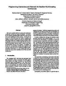
Figure 6.1: 2D schematic of the linked-list cell method. (a) Illustration of conventional linkedlist cell method with cell dimension Rs ≥ Rc. (b) 2D schematic of the reduced linked-list cell method. Atoms in the shaded region will be excluded from the force computation of center atom i. Only forces exerted by atoms within the cutoff radius (represented by a two-headed arrow) are computed.
129
Figure 6.1(a) shows a schematic of the computational kernel of MD, which employs a linked-list cell method to compute interatomic interactions in O(N) time. Periodic boundary condition is applied to the system in three Cartesian dimensions. Here, a simulation domain is divided into small rectangular cells, and the linked-list data structure is used to organize atomic data (e.g. coordinates, velocities and atom type) in each cell. By traversing the linked list, one retrieves the information of all atoms belonging to a cell, and thereby computes interatomic interactions. Thus, the cutoff radius Rc of the interatomic interaction usually determines the dimensions of the cells. In order to explain the computational procedures in the linked-list cell method, let us define S, which is a set of all atomic pairs, (i, j), within the nearest-neighbor cells. The first phase of the computation, i.e. pair search, constructs a subset, S0, of pairs (i, j) whose distance rij satisfies rij ≤ Rc. Subsequently, second phase computes the forces between all atom pairs within S0. Figure 6.2 shows the pseudocode for pair search and force computation. Phase 1: Pair search S0 = ∅
for ∀(i, j) ∈ S do if rij ≤ Rc do
€
S0 = S0 ∪ (i, j)
€
€
end €end
Phase 2: Force computation for ∀(i, j) ∈ S0 do compute interaction force €
f ij (rij )
end €
Figure 6.2: Force computation algorithm.
130
The reduced linked-list cell method attempts to reduce the search space S by decreasing the dimension Rs of the linked-list cell. To illustrate this, Fig. 6.1(b) shows the situation where Rs is reduced by half. The atoms in the shaded region are at least one cutoff distance away from the center atom i such that it can be safely excluded. Hence, less number of pairs needs to be evaluated, potentially resulting in the performance increase. However, this performance gain could be offset by the increased number of linked-list cells that need to be scanned (e.g., from 9 to 25 cells in the 2D example) and the associated computational overhead for processing the increased number of linked lists. The MD program used in this chapter is parallelized based on spatial decomposition and message passing [6]. However, the focus of this chapter is performance optimization within each compute node, and thus the number of atoms N hereafter denotes the number of atoms per node.
6.3 Performance Analysis Computing non-bonded interactions usually consumes the largest portion of time in MD simulation [23]. In our performance model, we assume that the computational cost consists of three terms: (1) pair search where the number of search operations Ps = |S|, i.e. the cardinality of set S (phase 1 in ); (2) force computation for which the number of force computation operations Pc = |S0| (phase 2 in ); and (3) linked-list cells access overhead—Pl. Therefore, the non-bonded computation time in one MD step—T, is
T = Ts Ps + Tc Pc + Tm Pl ,
(6.1)
where Ts, Tc, and Tm are the operation cost per Ps, Pc, and Pl, respectively.
131
Generally, the memory access cost (the third term in Eq. (6.1)) in the conventional cell decomposition method is ignored when compared to the pair-search and force-computation costs. However, in the reduced linked-list cell method, this overhead often becomes dominant. In section 6.3.1, we derive Ps, Pc, and Pl for the conventional cell-decomposition method, while the extension of the model to the reduced cell method is derived in section 6.3.2. The operation costs Ts, Tc, and Tm are obtained from regression described in section 6.3.3.
6.3.1 Short-Range Interaction Cost Model of the Conventional Linked-List Cell Method 6.3.1.1 Pair search cost model The search space for short-range force computations is defined as the number of pairs that need to be evaluated in phase 1 of . For N atoms, the search space of an all-pair method is O(N2). In this section, we derive the approximation of the O(N) search space in the linked-list cell method. For the uniform cell decomposition method with cubic cell dimension for all cells, the volume of each cell is Vc = Rs3 ,
(6.2)
where Rs is the dimension of the linked-list cell such that Rs ≥ Rc . If the number density of atoms in the system is ρ atom/Å3, the average number of atoms in one linked-list cell is Nc = ρ R . 3 s
€
(6.3)
The number of possible short-range pairs between atoms in two cells is then 132
Pcc =
1 1 1 N c ( N c −1) ≈ N c2 = ρ 2 Rs6 . 2 2 2
(6.4)
Let Cijk be a linked-list cell with cell indices i, j, and k in the x, y, and z directions, respectively. To compute forces exerted to all atoms in Cijk, all atom-pair combinations between Cijk and its nearest neighbor cells C"i j k need to be evaluated, where "
" "
Sneighbor (Cijk ) = {Ci!!j!k! (i −1 ≤ i! ≤ i +1)∧( j −1 ≤ j! ≤ j +1)∧(k −1 ≤ k! ≤ k +1)} ,
(6.5)
is the set of neighbor cells. Since the conventional cell decomposition method evaluates all atomic pairs between Cijk and its 26+1 neighbor cells (including itself), the number of pairs to be evaluated per one linked-list cell is 1 Ps (C ) = ρ 2 Rs6 N neighbor , 2
(6.6)
where Nneighbor = |Sneighbor| = 27. Let Lx, Ly, and Lz be the number of cells in the x, y and z directions, respectively, then the total number of atom pairs to be evaluated in one MD step is Lx
Ly
Lz
Ps = ∑∑∑ Ps (Cijk ) i=1 j=1 k=1
1 = ρ 2 Rs6 Lx Ly Lz N neighbor 2
.
(6.7)
6.3.1.2 Force computation cost model After the interaction pairs have been evaluated, only the pairs that satisfy the evaluation criterion (i.e., rij ≤ Rc) undergo force computation. The number of force computations can be estimated as follows. First, we count the number of atoms that are located inside the sphere with radius Rc around each atom. The volume of such sphere is
133
4 V fc = π Rc3 , 3
(6.8)
and the number of atoms that reside within Vfc is 4 N fc = πρ Rc3 . 3
(6.9)
Let N denote the number of atoms in the system. From Eq. (6.3), N can be expressed as N = ρ Rs3 Lx Ly Lz .
(6.10)
Combining Eqs. (6.9) and (6.10), the number of force computation operations—Pc is Pc = N fc N
. 4 = πρ 2 Rs3 Rc3 Lx Ly Lz 3
(6.11)
The number of pair-force computations in Eq. (6.11) can be halved by applying Newton’s 3rd law (i.e., the forces acting on a pair of atoms are equal and in the opposite directions) such that 2 Pc = πρ 2 Rs3 Rc3 Lx Ly Lz . 3
(6.12)
6.3.1.3 Linked-list cell access cost model Linked-list cell access cost refers to the overhead introduced by the cell decomposition scheme. To compute the forces on atoms in cell C, Nneighbor cells need to be traversed. Therefore, the number of linked-list cell accesses is
Pl = Lx Ly Lz N neighbor .
(6.13)
134
Combining Eqs. (6.7), (6.12) and (6.13), the prediction model for short-range pair computation is given by
!1 $ T = Ts # ρ 2 Rs6 Lx Ly Lz N neighbor & "2 % !2 $ +Tc # πρ 2 Rs3 Rc3 Lx Ly Lz & . "3 %
(6.14)
+Tm ( Lx Ly Lz N neighbor ) In the next subsection, we derive a corresponding model for the reduced cell method to be used to obtain the optimal cell dimension.
6.3.2 Short-Range Interaction Cost Model of the Reduced Linked-list Cell Method 6.3.2.1 Reduced-cell cost model In this subsection, we derive the number of searched pairs Ps", that of pair-force computations Pc", and that of linked-list accesses Pl", when the cell dimension Rs is reduced to
R Rs! = s , µ
(6.15)
where µ ∈ N is a cell dimension reduction factor. The cell dimension reduction also modifies the number of linked-list cells such that
L!x = µ Lx L!y = µ Ly .
(6.16)
Lz! = µ Lz
135
In the reduced cell method, the 1st-nearest neighbor cells are not sufficient for interaction evaluations, and instead up to the µth-nearest neighbor cells need to be evaluated. Therefore, Nneighbor can be calculated as 3
N neighbor = ( 2µ +1) .
(6.17)
Substituting Rs", Lx", Ly", Lz", and Nneighbor to Eqs. (6.7), (6.12), and (6.13), respectively, yield 1 Ps! = ρ 2 Rs!6 L!xL!yLz! N neighbor 2 6 1 2 " Rs % 3 3 = ρ $ ' µ Lx Ly Lz ( 2µ +1) , 2 #µ&
(2µ +1) = 2µ
3
3
ρ 2 Rs6 Lx Ly Lz
2 Pc! = πρ 2 Rs!3 Rc3 L!xL!yLz! 3 3 2 2 " Rs % 3 3 = πρ $ ' Rc µ Lx Ly Lz , 3 #µ& 2 = πρ 2 Rs3 Rc3 Lx Ly Lz = Pc 3
Pl! = L!xL!yLz! N neighbor 3
(6.18)
3
= µ ( 2µ +1) Lx Ly Lz
.
(6.19)
(6.20)
Equation (6.19) indicates that Pc" is independent of the reduction factor µ. This is consistent with the requirement that the choice of cell dimension should not affect the simulation results as noted by Heinz et al. [103].
136
6.3.2.2 Asymptotic analysis of the number of key operations In this section, we analyze the relation of the reduction factor µ to Ps", Pc", and Pl". This can be done by the expansion of Eqs. (6.18) and (6.20) in the power of µ:
#1 & Ps! = % µ −3 + 3µ −2 + 6µ −1 + 4 ( ρ 2 Rs6 Lx Ly Lz , $2 '
(6.21)
Pl! = (8µ 6 +12µ 5 + 6µ 4 + µ 3 ) Lx Ly Lz ,
(6.22)
while Pc" is independent of µ. Equations (6.21) and (6.22) provide asymptotic behaviors of Ps" and Pl" with respect to µ as summarized in . (The constant term of Ps", which is irrelevant for the determination of optimal µ, is omitted in ) Since Ps" and Pl" are descending and ascending functions of µ, respectively, the optimal µ value that minimizes the computation time is determined by their trade-off. The asymptotic analysis reveals that the increase of the number of linked-list cell accesses Pl" with µ is significantly larger than the reduction of search space Ps", while Pc" is not affected by µ. This implies that asymptotically, the overhead cost from linked-list access overwhelms the benefit due to the reduced the search space for large µ. This agrees with finding by Mattson et al. [101] and Yao et al. [102] such that the computation time is minimal when µ is small. From Eq. (6.1), the costs of pair search Ts and that of linked-list access Tm are essential parameters to quantify the trade-off between Ps and Pl, so that the optimal value of µ can be determined as described in section 6.4.
137
Table 6.1: Asymptotic complexity of parameter Ps", Pc", and Pl" over µ. Operation count
Scaling with reduction factor µ
Ps"
O(µ-3)
Pc"
O(1)
Pl"
O(µ6)
6.4 Model Validation As derived in section 6.3, the computation time for short-range interactions in the reduced linked-list cell method is given by T = Ts Ps! + Tc Pc! + Tm Pl! " ( 2µ +1)3 % 2 6 ' = Ts $$ ρ R L L L s x y z' 3 2 µ # &. "2 % +Tc $ πρ 2 Rs3 Rc3 Lx Ly Lz ' #3 &
(
3
+Tm µ 3 ( 2µ +1) Lx Ly Lz
(6.23)
)
In section 6.4.1, we validate the accuracy of the operation-counts models—Ps", Pc", and Pl"—by comparing them with measured values. In section 6.4.2, we fit the Ps", Pc", and Pl" derived from the estimation, Eq. (6.23), to obtain the operation costs—Ts, Tc, and Tm.
6.4.1 Validation of the Operation Counts Model MD simulations of silica at temperature 300 K involving up to 192,000 atoms are performed on an Intel Core-i7 2.66 GHz machine, using the cell reduction factor µ ranging from 1 to 4. The cutoff radius Rc of this dataset is set to 5.5 Å with atom density ρ = 0.0654 atom/Å 3, and the linked-list cell size Rs = 5.728 Å. 138
Under this condition, the actual values of Ps", Pc", and Pl" measured during the simulations are compared with those obtained from the model; see Table 6.2. The relative error of Ps" and Pl" is less than 4% in all cases, confirming the applicability of our model for these parameters. For Pc", the relative error is ~ 10% for the largest number of atoms (N = 192,000), while it is ~ 8% for the smallest system (N = 1,536). Nevertheless, the maximum error of 10% is acceptable for the subsequent analysis, especially in the light of the highly dynamic nature of MD simulations. Table 6.2: Accuracy of the operation counts model. Relative error (%) Number of atoms Reduction factor, µ
1,536
12,288
41,472
98,304
Ps"
Pc"
Pl"
1
1.67
8.01
3.60
2
1.31
8.01
0.70
3
0.96
8.01
0.19
4
0.95
8.01
0.04
1
0.79
-0.51
3.50
2
0.76
-0.51
0.60
3
0.49
-0.51
0.09
4
0.39
-0.51
-0.06
1
-0.24
-2.28
2.68
2
-0.21
-2.28
-0.20
3
-0.40
-2.28
-0.70
4
-0.31
-2.28
-0.85
1
-1.43
-3.29
1.67 139
192,000
2
-1.35
-3.29
-1.18
3
-1.42
-3.29
-1.67
4
-1.59
-3.29
-1.83
1
-3.50
-10.59
-0.28
2
-3.29
-10.59
-3.08
3
-3.39
-10.59
-3.57
4
-3.38
-10.59
-3.71
6.4.2 Parameter Fitting In section 6.4.1, we confirm that Eq. (6.23) accurately approximates the operation counts. In this section, we use the prediction from the model and the running time from the execution of actual MD simulation to find the cost parameters Ts, Tc, and Tm. Here, we need to use more datasets in order to get better statistics for the fitting. Since Rc is one of the most important variables, we here concentrate on the effect of Rc on the performance. We run two additional sets of MD simulations using the same setting as in section 6.4.1 except for Rc, which is set here to 6.6 and 10 Å. Using the measured timings, we perform least square regression to obtain Ts, Tc, and Tm from Eq. (6.23). However, the results obtained from the least square regression show very large error up to 93% for estimated Tc; see . This may be explained by the two orders-of-magnitude difference between the largest and smallest dataset sizes (1,536 and 192,000 atoms), which causes the fitting residuals of larger datasets to dominate the significance of smaller datasets. To alleviate this artifact, a more robust regression algorithms, Huber regression and bisquare-weighted regression, are used instead of the least square regression [104, 105]. Table 6.3 shows that the estimated operation costs from Huber
140
regression have smaller standard errors (at most 40.8%), while those from bisquare-weighted regression have the least errors (at most 22.5%). Therefore, we use the estimated costs from bisquare-weighted regression to predict the performance and thereby obtain the optimal reduction factor µ in the next section. Table 6.3: Estimated operation costs from various regression algorithms. Regression algorithm
Least square
Operation cost
Estimated cost (ns)
Standard error (%)
Ts
9.76
40.2
Tc
34.83
93.1
Tm
10.44
7.6
Ts
6.48
22.2
Tc
52.89
22.5
Tm
11.80
2.5
Ts
10.77
14.9
Tc
32.56
40.8
Tm
10.81
3.0
Bisquare c = 1.865
Huber c = 1.345
6.5 Performance Results Here, we use the estimated operations counts and costs in the previous section to predict the performance of the simulation when the cell size is reduced. The optimal reduction factor µ* is then determined as the one that minimizes the predicted computation time:
µ * = arg min (T (µ )) .
(6.24)
141
To study the computation time as a function of µ from the prediction, we compare the predicted and measured performances of the system with Rc = 5.5, 6.6, 10.0 Å, with the number of atoms ranging from 1,536, 12,288, 41,472, 98,304, to 192,000. Figure 6.3 shows that the prediction captures the essential behavior of the short-range computation time in the actual simulations as a function of µ. This result agrees with the asymptotic characteristics of µ in Table 1, where the linked-list cell access cost dominates for larger µ. Figure 6.4 compares µ* obtained from the prediction, Eq. (6.23), with those obtained from actual measurements. The µ* for Rc = 5.5 Å from actual simulation dataset are all 1, similar to the predicted values. Namely, reducing the cell dimension does not improve the performance in this case. On the other hand, the predicted µ* of the system with Rc = 6.6 and 10.0 Å is 2 in almost all cases with the average speedup of 1.10 and 1.52, respectively. This result indicates that the reduction of the cell dimension becomes more beneficial for larger Rc. In such cases, the pair search space is larger and the associated search cost Ps" becomes more important relative to the list-processing overhead Pl". Table 6.4 shows the speedup achieved from our optimization compared to the actual optimal speedup.
142
Figure 6.3: The running time from the prediction and the measurement for Rc = 10 Å. The numerals are the number of atoms.
Figure 6.4: Comparison of speedup gained from predicted and actual μ* for Rc = 6.6 and 10 Å.
143
Table 6.4: The predicted versus measured values of the optimal µ with their corresponding speedup compared to the case of no cell dimension reduction.
Rc (Å)
5.5
6.6
10.0
Speedup
µ*
N Prediction
Actual
Prediction
Actual
1,536
1
1
1.00
1.00
12,288
1
1
1.00
1.00
41,472
1
1
1.00
1.00
98,304
1
1
1.00
1.00
192,000
1
1
1.00
1.00
1,536
2
2
1.12
1.12
12,288
2
2
1.28
1.28
41,472
2
1
0.92
1.00
98,304
2
2
1.15
1.15
192,000
2
2
1.02
1.02
1,536
3
3
1.85
1.85
12,288
3
2
1.54
1.74
41,472
2
2
1.41
1.41
98,304
3
2
1.54
1.70
192,000
2
2
1.28
1.28
144
6.6 Summary We have developed a performance prediction model of short-range interaction computations of molecular dynamics simulations, which can be used to obtain the optimal cell dimension in the reduced linked-list cell algorithm. The model has been validated against measurement results. The model accurately predicts the optimal reduction factor, and average speedup of 1.10 and 1.52 are obtained for Rc = 6.6 and 10.0 Å datasets, respectively. Our analysis reveals that the optimal reduction factor is determined by a trade-off between decreasing search space and increasing linked-list cell access for smaller cells.
145
Chapter 7
Memory-Access Analysis and Optimization via Dynamic Data Reordering
One of the major problems on improving performance of sophisticated scientific applications such as MD simulation is to maintain data locality. Since the memory-access pattern in MD simulation is highly non-uniform and unpredictable, the locality optimization problem becomes even more challenging. The impact of this issue leads to a fluctuation of MD simulation performance. The unstable performance is intolerable for the design of performance model, thus need to be addressed. In this chapter, we first discuss the causes of performance fluctuation from poor memory-access pattern. We then propose a solution by dynamic data reordering. This chapter is organized as follows. Section 7.1 presents the parallel MD program, to which the proposed memory optimization scheme is implemented. Section 7.2 describes the analysis of simulation parameters related to data fragmentation. Section 7.3 presents the performance measurements and discusses the correlation between fragmentation and
146
performance. Section 7.4 proposes our adaptive memory-access optimization scheme based on data fragmentation analysis and performance measurements. Summary is shown in section 7.5.
7.1 Introduction A commonly used method to reduce the performance fluctuation from poor data locality issue is data reordering. Data reordering organizes data of irregular memory-access patterns in memory according to a certain locality metric [102, 106-108]. However, a further challenge arises from the dynamic, irregular nature of MD computations. Mellor-Crummey et al. [109, 110] showed that data reordering and computation restructuring enhance data locality, resulting in the reduction of cache and translation-lookaside buffer (TLB) misses and accordingly considerable performance improvement of MD simulations. The study also suggested the necessity of repeated runtime reordering, for which the remaining problem is how often the reordering should be performed in order to achieve the optimal overall performance. In addition, as the data reordering and computation restructuring incur computational overhead, such reordering cost should be considered to find the optimal reordering frequency. Runtime data behaviors of MD simulations are closely related to both physical properties of the system being simulated (e.g. temperature, diffusion rate, and atomic configuration) and computational parameters (e.g. spatial decomposition granularity in parallel MD). Therefore, understanding how these quantities affect the deterioration of data locality is a prerequisite for designing the optimal runtime data-reordering schedule. To address these challenges, we first introduce a data fragmentation ratio metric that quantifies the locality of atom data arrays during MD simulation. Then, we perform an analysis on how MD simulations with different physical/computational characteristics (e.g. temperature, 147
diffusion rate, and granularity) impact the data fragmentation ratio and performance deterioration of the system. Based on the data fragmentation analysis, we finally design and evaluate an adaptive memory optimization scheme that features an optimal runtime data-reordering schedule during MD simulation.
7.2 Data Fragmentation in Parallel Molecular Dynamics High memory-access penalty is a major obstacle of irregular memory accessing applications, which needs to be mitigated. Our MD application performs data and computation orderings by organizing atom data contiguously in memory in the same order as the linked lists of the cells access them. Though the spatial locality after data reordering is retained for a while, data get disordered as simulation progresses due to atom movement among cells. How the benefit from data reordering deteriorates as simulation evolves at runtime essentially affects the performance of MD simulations. To quantify the level of fragmentation, we first define a fragmentation measurement ratio metric. Let C(i, j, k) be a linked-list cell with cell indices i, j, and k in the x, y, and z directions, respectively. Each linked-list cell contains indices of atoms whose coordinates are within their cell dimensions. Before data reordering, atom data are likely scattered in memory as illustrated in Figure 7.1(a), and data reordering improves the data locality as shown in Figure 7.1(b), where the atom data of the same physical cell volume reside continuously. Fragmentation in the atom data array could occur as follows. Suppose that the a-th atom in linked-list cell C moves to another cell C". Consequently, the memory block of C" becomes partially fragmented because the a-th atom is not contiguous in memory space with other atoms in C" such that their distances in the memory space exceed the page size. Therefore, any atom moving out of its original linked148
list cell introduces fragmentation in memory, which likely causes data translation lookaside buffer (DTLB) misses. To quantify the degree of fragmentation, we thus define a data fragmentation ratio as
f=
N fragment , N
(7.1)
where Nfragment is the number of atoms whose positions have moved out of the originally ordered cells and N is the total number of atoms. The data fragmentation ratio is between 0 (i.e., all atoms in all cells reside continuously in memory—fully ordered state, see Figure 7.1(b)) and 1 (i.e., no atom resides in the original cell—fully disordered state, see Figure 7.1(a)). The data fragmentation ratio will be used to quantify fragmentation extensively throughout this chapter. Note that the page size used in all experiments is 4 KB.
Figure 7.1: Schematic of memory layout for atom data in (a) a fully disordered state and (b) a fully ordered state, where C(i,j,k) is the linked list for the cell with indices i, j, and k in the x, y, and z directions, respectively, r[a] is the data associated with the a-th atom. 149
Data fragmentation in memory is dictated by the dynamics of atoms, and thus understanding the factors that control the atom dynamics would provide an insight on how to prevent the fragmentation. One of the physical factors that are directly related to the dynamics is the temperature, since high temperature drives atoms to move faster and more freely. Among the computational factors, migration of atom data from one node to another across a subsystem boundary in parallel MD also causes fragmentation. The granularity of spatial decomposition (i.e. the number of atoms per compute node) is related to the subsystem surface/volume ratio, and hence is likely to control the degree of fragmentation via the amount of atom migrations. In the following subsections, we measure and analyze the effects of temperature and granularity on the data fragmentation: Sections 7.2.1 and 7.2.2 deal with fragmentation behavior influenced by temperature and granularity, respectively.
7.2.1 Temperature Induced Fragmentation In this subsection, we study the effect of temperature on the data fragmentation during MD simulations on two systems: Silica material [111] and combustion of aluminum nanoparticles [112]. The silica simulations involving 98,304 atoms and 8,000 linked-list cells (20×20×20 in x, y, and z directions, respectively) are performed for 3,000 MD time steps using a time discretization unit of 2 femtoseconds. The simulations are performed on a dual quadcore Intel Xeon E5410 2.33 GHz (Harpertown) at the High Performance Computing and Communication (USC-HPCC) facility of the University of Southern California. Temperature is a major physical factor that enhances the diffusion of atoms and hence the disordering of data arrays. To examine the effect of atomic diffusions on the data fragmentation ratio, we thus perform a set of simulations with three different initial temperatures, 300 K, 3,000 K, and 6,000 K, starting from the same initial atomic configuration—an amorphous structure with a uniform 150
density across the system. Each dataset represents a distinct phase of silica—solid (300 K), highly viscous liquid (3,000 K) [113], and low-viscosity liquid (6,000 K) (note that the melting temperature of silica is 1,800 K). Here, data ordering is performed only once at the beginning of the simulation, so that the atom data are fully ordered (Figure 7.1(b)) initially, and subsequently we measure the data fragmentation ratio as a function of MD steps without further data reordering. In order to study the influence of temperature on data fragmentation, Figure 7.2 plots the data fragmentation ratio as a function of MD steps. We observe that simulations at higher temperatures exhibit larger fragmentation ratios. The fragmentation of 300 K dataset fluctuates in the first 500 steps, then rises to 0.15 after 1,000 steps, and remains nearly constant throughout the simulation thereafter. At 3,000 K, the fragmentation ratio quickly increases to 0.24 in the first 200 steps, and then increases linearly with time (0.033 per 1,000 steps), reaching 0.36 after 3,000 MD steps. In contrast, the fragmentation ratio at 6,000 K rapidly rises to 0.73 in the first 500 steps, then continues to increase with a slightly slower rate until the data gets almost fully disordered at 0.93 after 3,000 MD steps.
151
Figure 7.2: Time variation of data fragmentation ratio over 3,000 MD steps. Three datasets of different initial temperatures (300 K, 3,000 K, and 6,000 K) are plotted. In order to understand the physical origin of the correlation between the fragmentation ratio and temperature in Figure 7.2, we measure the mean squared displacement (MSD) of atoms in each dataset as a function of time. MSD is used to identify the phase (e.g. solid vs. liquid) of the material and to calculate the diffusion rate of atoms in the system, which may be used to quantify the dynamics of atoms during the simulation. Figure 7.3 shows the MSD of 300 K, 3,000 K, and 6,000 K datasets over 6 picoseconds (3,000 MD steps). The result shows that at 300 K, silica remains in solid phase (MSD remains constant). In contrast, 3,000 K silica is melted and becomes a highly viscous liquid with a small diffusion coefficient of 2.31×10⁻⁵ cm2/s (the diffusion coefficient is obtained from the linear slope of the MSD curve). Similarly, MSD of 6,000 K dataset shows that the system is completely melted with a much larger diffusion coefficient of 4.17×10⁻⁴ cm2/s. Because atoms are not diffusing in 300 K dataset, 83% of the atoms (f = 0.17) remain in the same linked-list cell throughout the simulation. Only atoms close to the cell boundaries move back and forth between the original and the neighbor cells due to 152
thermal vibration. However, atoms in 3,000 K dataset are melted, and their slow diffusion from their original cells causes the gradually increasing fragmentation ratio. For 6,000 K system, atoms diffuse approximately 18 times faster than 3,000 K system, resulting in the rapid rise of fragmentation ratio. Only 3.2% of the atoms remain in the same cell after 3,000 steps. These results clearly show that diffusion is a major physical factor that contributes to data fragmentation in MD simulations.
Figure 7.3: Mean squared displacement (MSD) of 300 K, 3,000 K, and 6,000 K datasets. The MSD of 300 K dataset remains constant at 0.23 Å2 (too small to be seen in the figure). The inset shows the diffusion coefficients at the three temperatures. Although the silica experiment shows that the temperature significantly affects data fragmentation, we also found that its effect on the fragmentation ratio is sensitive to the material and phenomenon being simulated. To demonstrate this point, the second experiment simulates flash heating of an aluminum nanoparticle surrounded by oxygen environment using a reactive interatomic potential [112], which involves 15,101,533 atoms on 1,024 processors of dual core AMD Opteron 270 2.0 GHz (Italy) at the USC-HPCC facility. Similar to the first simulation, the
153
atom data arrays are ordered only once at the beginning of the simulation. Then, the fragmentation ratio of 3,000 K, 6,000 K and 9,000 K datasets are measured at each step. Figure 7.4 shows the data fragmentation ratio as a function of MD steps. We see that the fragmentation ratios of all datasets rapidly rise to above 90% after 1,000 MD steps, and continue to increase to over 98% after 2,000 MD steps. Since the aluminum nanoparticles are at considerably high temperatures (far above the melting temperature of aluminum ~ 930 K) and are surrounded by oxygen atoms in the gas phase, the atoms are highly reactive and move very rapidly. This accelerates the fragmentation to proceed very quickly regardless of the temperature. In such applications, data reordering is indispensable and is required to be performed more often in order to maintain good spatial locality. These results indicate that fragmentation is highly system dependent, so that data reordering needs to be performed dynamically at runtime, adapting to the system’s behaviors.
Figure 7.4: Data fragmentation ratio during aluminum combustion simulation over 2,000 MD steps. The dataset involves 15 million atoms on 1,024 processors.
154
7.2.2 Granularity Induced Fragmentation In addition to fragmentation induced by physical properties, parallel MD using spatial decomposition introduces computational artifacts such as spatial subsystem (or domain) boundaries, which also contribute to the fragmentation of atom data arrays. In this subsection, we study the influence of granularity (i.e. the number of atoms per compute node) on data fragmentation. Atoms near a domain-boundary surface tend to migrate among domains regardless of physical simulation conditions. This inter-domain atomic migration triggers rearrangements of data arrays, including the deletion of the migrated atom data from the original array, compression of data array after the removal of the migrated atoms, and their appending to the array in the destination domain. These newly migrated atoms in the destination domain cause data fragmentation, since they do not reside continuously in memory. To confirm the expected high fragmentation ratio at the domain boundaries as explained above, the data fragmentation ratios of the surface cells (i.e. the outer-most layer cells that share at least one facets with the inter-domain surfaces) and core cells (i.e. non-surface cells deep inside each domain) are measured separately. Here, we consider a 12,288-atom silica dataset initially at 3,000 K temperature similar to the dataset used in the first experiment of section 7.2.1 but with a reduced domain size (their dimensions are reduced by half in all three directions, so that the domain volume is one-eighth of that in section 7.2.1). This dataset consists of 1,000 cells in total (10×10×10), of which 488 cells (48.8%) are surface cells. Figure 7.5(a) clearly shows that the data fragmentation ratio of the surface cells is larger than that of the core cells. In the first 100 MD steps, the fragmentation ratios of the two groups are almost identical. Then, the fragmentation ratio of the surface cells begins to increase at higher rate reaching 0.53 after 3,000 MD steps, whereas the fragmentation ratio of the core cells is only 0.39. Thus, the atom data of 155
the surface cells is 14% more fragmented that that in the core cells, yielding a total fragmentation ratio of 0.42 for the entire system. This result confirms that computational artifacts such as domain boundary indeed induce additional fragmentation.
Figure 7.5: (a) Time variation of the data fragmentation ratio of 12,288-atom silica at 3,000 K over 3,000 MD steps, for surface cells, core cells, and both combined. (b) Time variation of the data fragmentation ratio of 3,000 K silica with varying granularities over 3,000 MD steps.
156
The domain-boundary induced fragmentation also implies that systems with smaller granularities will have more fragmentation due to their larger surface/volume ratios (i.e., larger portions of linked-list cells are domain-boundary cells). To test this hypothesis, we perform MD simulations for 3,000 K silica system with three different granularities—98,304, 12,288, and 1,536 atoms, over 3,000 MD steps. The dimensions of the three systems are summarized in Table 7.1, which shows that the surface-to-volume ratio ranges from 27.1% for N = 98,304 to 78.4% for N = 1,536. Asymptotic analysis of surface-to-volume ratio shows that the ratio scales as O(N-1/3). Figure 7.5(b) shows that datasets with smaller granularities indeed have larger fragmentation ratios. After 3,000 MD steps, the data array of the smallest granularity (1,536 atoms) dataset is 9.7% more fragmented than that in the largest granularity (98,304 atoms) dataset. Also, the 12,288 atoms dataset is 5.2% more fragmented compare to the largest dataset. The figure also shows large fluctuation for the fragmentation ratio for N = 1,536 dataset, due to less statistics inherent for the small system size. Table 7.1: 3,000 K silica datasets with varying granularities: The number of linked-list cells, the portion of surface cells, and the surface-to-volume ratio of the spatial subsystem are listed for each dataset. Number of
Number of
atoms
cells
System dimensions (cells)
Portion of surface
Surface-to-volume
cells (%)
ratio (Å -1)
1,536
125
5×5×5
78.4
0.111
12,288
1,000
10×10×10
48.8
0.055
98,304
8,000
20×20×20
27.1
0.027
157
7.3 Performance Measurement In the pervious section, we described how physical and computational parameters of MD simulations affect the data fragmentation behavior in the memory space, utilizing the data fragmentation ratio as a metric. In this section, we first establish a correlation between the data fragmentation ratio and the performance of the program. In a fragmented dataset, atom data are likely to reside in different memory pages, which causes a large number of DTLB misses, when they are fetched. The reordering algorithm explained in section 7.2 clusters atom data that need to be fetched and computed in relatively proximate times (e.g. atoms in the same cells) in the same page, thereby reducing DTLB misses tremendously. However, as the simulation progresses, atoms that are once ordered possibly move out of their original cells. It is thus expected that the increase of DTLB misses caused by data fragmentation is a major source of performance degradation in MD. To confirm the correlation between the number of DTLB misses and the data fragmentation ratio, we perform a test using the same datasets from the first experiment of section 7.2.1 (98,304 silica atoms with initial temperatures of 300 K, 3,000 K, and 6,000 K). In addition to the fragmentation ratio measured in section 7.2.1, we here measure the DTLB miss rate as a function of MD steps. We use the Intel VTune Performance Analyzer to monitor DTLB miss events during MD simulation on Intel Core i7 920 2.67 GHz (Nehalem) processor. We measure the number of DTLB misses after data ordering is performed, then normalize it by the original number of DTLB misses without data ordering. We find that the initial DTLB miss rates at all temperatures are approximately 0.07 (