Nat. Hazards Earth Syst. Sci. Discuss., doi:10.5194/nhess-2017-44, 2017 Manuscript under review for journal Nat. Hazards Earth Syst. Sci. Published: 6 February 2017 c Author(s) 2017. CC-BY 3.0 License.
Method and application of using unmanned aerial vehicle for emergency investigation of single geo-hazard Haifeng Huang1, 2, 3, Jingjing Long2, 3, Wu Yi3, 4, Qinglin Yi3, 4, Guodong Zhang3, 4, Bangjun Lei1 1
5
Hubei Key Laboratory of Intelligent Vision Based Monitoring for Hydroelectric Engineering, China Three Gorges
University, Yichang 443002, China 2
Key Laboratory of Disaster Prevention and Mitigation of Hubei Province, China Three Gorges University, Yichang 443002,
China 3
National Field Observation and Research Station of Landslides in the Three Gorges Reservoir Area of Yangtze River, China
Three Gorges University, Yichang 443002, China
10
4
Collaborative Innovation Center for Geo-Hazards and Eco-Environment in The Three Gorges Area of Hubei province,
Yichang 443002, China Correspondence to: Jingjing Long (
[email protected])
15
Abstract. In recent years, the unmanned aerial vehicle (UAV) began to be widely used in the emergency investigation of major natural hazards in a large area, but less for the single geo-hazard. Based on a number of successful practices in the Three Gorges Reservoir Area, China, a complete UAV-based emergency investigation method of single geo-hazard is concluded. Firstly, a customized UAV system consisting of multi-rotor UAV subsystem, aerial photography subsystem, ground control subsystem and ground surveillance subsystem is described in detail. Then, the implementation process which includes four
20
steps, i.e., indoor preparation, site investigation, site fast processing and applying, and indoor comprehensive processing and applying is elaborated, and two investigation schemes including automatic and manual in the site investigation step are put forward. Moreover, some key techniques and methods, e.g., the ground controls points (GCPs) layout and measurement, the route planning, the flight and shooting process control, and the Structure from Motion (SfM) photogrammetry processing are explained. Finally, three applications are given. Practice shows that, using the UAV for emergency survey of single geo-hazard
25
can not only greatly reduce the time, strength and risks of the on-site work, but also provide high-accuracy, high-definition valuable information to well support the emergency treatment. Keywords. single geo-hazard; landslide; emergency investigation; unmanned aerial vehicle (UAV); emergency treatment
1 Introduction 30
The aim of the emergency investigation is to provide basic and essential information including disaster characteristics, loss situations and environmental conditions, etc., for the single geo-hazard emergency decision-making and effective treatment, so it is therefore a top priority, and needs to emphasize the speed and efficiency of the implement process, and the accuracy of the results (Liu, 2006; Liu et al., 2010; Lu and Xu, 2014). In general, the traditional method of emergency investigation for 1
Nat. Hazards Earth Syst. Sci. Discuss., doi:10.5194/nhess-2017-44, 2017 Manuscript under review for journal Nat. Hazards Earth Syst. Sci. Published: 6 February 2017 c Author(s) 2017. CC-BY 3.0 License.
single geo-hazard is used, i.e., the specialist go around and inspect on the disaster body with cameras and simple measurement
35
tools, then conclude information based on the field investigation and professional knowledge. There is no doubt that these efforts in the traditional method require more manpower, longer working hours and greater work intensity, and often face difficulties in the inaccessibility of humans to certain areas of the geo-hazard, such as high cliffs or lush vegetation covered. In particular, these on-site investigators have to take the great risks of further disasters that may occur during the process of the emergency investigation. In addition, the conclusions of the investigation are often inaccurate, because they are mostly
40
local, qualitative or speculative-based, even some quantitative results such as the length, width, or area of a geo-hazard may have a large deviation from the actual situation. Therefore, relying solely on the traditional ground-based emergency investigation method would inevitably reduce the efficiency and effectiveness for the single geo-hazard emergency decisionmaking and treatment. Remote sensing features in fast, macroscopic, high resolution, and has the irreplaceable advantage in the fields of emergency
45
investigation of major natural hazards (Joyce et al., 2009; Boccardo and Tonolo, 2015). Along with the rapid development of unmanned aerial vehicle (UAV) remote sensing technology, it has been widely used in geo-hazards emergency investigation for some unique advantages (Lewis, 2007; Adams et al., 2014; Li et al., 2014; Fernandez Galarreta et al., 2015), such as low cost, easy manipulation, less risk and efficient image acquisition, etc. For example, in USA, the UAVs were used for damage inspections after the Hurricane Katrina (Pratt et al., 2006) and Hurricane Wilma and Ike (Steimle et al., 2009); in Taiwan, a
50
helicopter UAV was used to collect imagery to support post-disaster reconnaissance, disaster restoration and reconstruction assessments after the Typhoon Morakot (Chou et al., 2010); in addition, the UAVs have gradually become the indispensable mean for disaster investigation and assessment after earthquakes, e.g. the Wenchuan earthquake in 2008 (Zhou et al., 2008), the L’Aquila earthquake in 2009 (Quaritsch et al., 2010), the Haiti earthquake in 2010 (Huber, 2010), the Japan earthquake in 2011 (Ackerman, 2011), the Lushan earthquake in 2013 (Xu et al., 2014), etc. However, above applications show that the
55
UAVs are mainly used in the emergency investigation or the loss assessment of major natural hazards, e.g., earthquakes or the secondary geo-hazards, e.g., landslides and rock collapses in a large area caused by major natural hazards. These UAV systems are usually large, complex and costly, and the acquisition of the final results also requires a very professional process with a long time. Actually, in the annual occurrence of a large number of geo-hazards, the single disasters with relatively small area accounted for vast majority, e.g., in 2015, a total of 8,224 geo-hazards (landslides accounted for the vast majority) occurred in
60
the mainland of China, of which 8,180 were medium (0.1-1.0 million m3) and small (less than 0.1 million m3) sized, accounting for 99.5%, and the direct economic losses were 200 million USD, accounting for 55.8% (Mlr P.R. China, 2015). It can be seen, on one hand, emergency investigation and treatment of single geo-hazards is very necessary for disasters prevention and mitigation, on the other hand, because of potentially greater losses and huge amounts, it usually requires more efficient and effective, e.g., only a few days or even hours to be given to propose the treatment measures.
65
In this case, more
simple, flexible and small-sized UAV system, as well as more quick, efficient on-site image acquisition method and UAVbased remote sensing results processing method had to be used, to ensure that in the shortest possible time to complete the whole airborne-based emergency investigation procedures, then providing valuable information for the subsequent works such as ground-based investigation or emergency treatment design. However, there is no complete, systematic and effective method of using UAV for the single geo-hazard emergency investigation at present, many challenges, e.g., the lack of customized UAV 2
Nat. Hazards Earth Syst. Sci. Discuss., doi:10.5194/nhess-2017-44, 2017 Manuscript under review for journal Nat. Hazards Earth Syst. Sci. Published: 6 February 2017 c Author(s) 2017. CC-BY 3.0 License.
70
system, the lack of a sound on-site implementation process and methods, etc., are hampering the specific applications. The main aim of carrying out this study is expected to base on a number of successful practices of using UAV to emergency investigate single geo-hazards in the Three Gorges Reservoir Area, China, in recent years, to conclude and establish a complete method of using UAV for emergency investigation of single geo-hazard, which include the customized UAV, the implementation process of UAV-based investigation, the key techniques and methods during the investigation and results
75
processing. And finally, three applications are given to demonstrate the applicability of the proposed method.
2 Customized UAV Most of the single geo-hazards (mainly refers to landslides, rock collapse and debris flow) that need to be emergency investigated, although generally of medium or small size, are often located in mountainous area with rugged topography, where only a limited range of visible observed from the ground view, and with changeable meteorological conditions, e.g., uncertain
80
wind power and direction. Besides, they are often located in the traffic arteries or crowded places, such as tourist attractions, where usually have many buildings and variety of public facilities, e.g., telecommunications and power towers and lines, etc., which revolve around or cross through the entire disaster. Therefore, in order to fully adapt to the complex environment in which the geo-hazard may be located, the UAV for carrying out the emergency investigation should meet some basic requirements, including: small size, light weight, quick assembling and disassembling; easy taking off and landing, no special
85
site requirements; simple, flexible and convenient control of flight and taking photos; stable flight control system, perfect failure protection function; strong wind resistance, reliable aerial gimbals of carrying camera; powerful ground control station, stable image and data transmission system; a certain endurance that guaranteeing a flight can cover the whole area of the most single geo-hazards. According to above requirements, combined with the comprehensive consideration of applicability, security, stability and
90
economy (mainly refers to the low cost of initial construction and later maintenance of the UAV system), a number of on-site tests and practical applications were carried out for the single landslides in the Three Gorges Reservoir Area, China, and finally a UAV system was customized, Fig. 1 shows the photo, the system architecture and the main function modules are shown in Fig. 2, and the core components and main features of the customized UAV are shown in Table 1. The customized UAV system consists of four subsystems, including multi-rotor UAV subsystem, aerial photography
95
subsystem, ground control subsystem and ground surveillance subsystem, details as follows: (1) A customized four-axis and eight-rotor carbon fiber airframe is used. The outstanding advantages of this design include high strength, strong power and light weight (the whole aircraft with camera and aerial gimbals is less than 5 kg). And compared with the fixed wing aircraft, it has smaller size, better maneuverability and more fixed-point hovering capability, in particular, no special sites for taking off and landing are required, which is very important for the use of UAV to quickly
100
investigate the single geo-hazards that are usually located in complex environment.
Although the endurance is poor, i.e.,
approximately 20 minutes of flight time, if calculated at an usual average flight speed of 5 m/s, the flight distance of about 5 km can guarantee that one flight is sufficient to cover the whole area of the most single geo-hazards. Even if multiple flights are required, only the battery needs to be replaced. (2) The flight control system, directly controls the processes of flight and shooting, is the "brain" of the UAV system, and
3
Nat. Hazards Earth Syst. Sci. Discuss., doi:10.5194/nhess-2017-44, 2017 Manuscript under review for journal Nat. Hazards Earth Syst. Sci. Published: 6 February 2017 c Author(s) 2017. CC-BY 3.0 License.
105
its performance and stability directly determine the function and the security of the whole system. Nowadays, there are many mature commercial products of flight control system, but they are closed-source systems, so in the event of failure, the only thing to do is to return to the factory for repair or re-purchase, resulting in high economic and time costs. Therefore, a widely used open source flight control system, i.e., PIXHAWK 2.4.5 (Meier et al., 2012) with dual processors is used, and its high robustness and powerful data processing capacity have been recognized. Equipped with high-performance global positioning
110
system (GPS), data and image transmission modules, etc., the flight control system can totally support some necessary functions such as route planning, flight positioning, real-time data and image transmission and so on. (3) The aerial photography subsystem, used for overhead or oblique shooting high-resolution images of the geo-hazards, to serve as the core data source of the emergency investigation information. Thanks for the rapid development of new digital photogrammetric technologies, especially represented by the Structure from Motion (SfM) photogrammetry (Westoby et al.,
115
2012; Li et al., 2013), which is developed based on computer vision algorithm, the requirements of early aerial photography equipment is greatly reduced. Therefore, only a Sony HX200 digital camera, with 18 mega effective pixels, and Vario Sonnar T* 4.8-144mm F/2.8–5.6 lens, is used to take photos. And in order to keep camera stability to ensure clear shooting, or accurately adjust the lens orientation according to actual needs, a three-axis brushless aerial gimbals is used to carry the camera. The camera shutter and the aerial gimbals are all controlled by the flight control system.
120
(4) The ground control subsystem, mainly includes ground control station, which is a notebook computer equipped with UAV’s ground control software. To match with Pixhawk flight control system, the corresponding open source ground station software, i.e., Mission Planner 1.3.37 (Team, 2016) is used. And by interacting with flight control system, the software can achieve some core functions including UAV’s debugging and maintenance, parameter settings, route planning, monitoring and control, etc., in a word, by using ground control station and flight control system, the whole process of flight and photos
125
shooting can be fully automated. In addition, a remote controller is used to control the flight by manual way in case of emergency. (5) The ground surveillance subsystem should be established to display real-time flight images and flight state data, which provide timely and accurate information for operators to make effectively judgment, decision, and manipulation, to ensure the flight safety. There is a key on-screen-display (OSD) module, by which the flight state data is superimposed on the real-time
130
flight images. And then all these information are transmitted to the ground terminal monitor by using image transmission system (including image delivery module on aircraft, and image receiving module on ground terminal monitor). Our customized UAV system has carried out more than ten missions of emergency investigation for single geo-hazards in the Three Gorges Reservoir Area. On one hand, the satisfactory photos of every geo-hazard had been obtained, and on the other hand, there has not been a runaway accident, which fully proved that the system has a positive applicability, safety and
135
reliability.
3 Implementation process The implementation process of using UAV to emergency investigate the single geo-hazard can be divided into four steps, i.e., indoor preparation, site investigation, site fast processing and applying, and indoor comprehensive processing and applying. Fig.3 shows detailed processes and tasks of every step, elaborated as follows.
4
Nat. Hazards Earth Syst. Sci. Discuss., doi:10.5194/nhess-2017-44, 2017 Manuscript under review for journal Nat. Hazards Earth Syst. Sci. Published: 6 February 2017 c Author(s) 2017. CC-BY 3.0 License.
140
3.1 Indoor preparation Performing the necessary indoor preparation can improve the efficiency of on-site emergency investigation, and mainly includes battery charging, UAV system initial inspection, and preliminary route planning.
3.1.1 Battery charging At present, our system components are used lithium battery-powered. To protect the efficiency and prolong the service life of
145
all lithium batteries, when they are not used, the voltage of every lithium cell should be maintained at 3.8v or so (Broussely, 2002), that is neither fully charged nor fully empty. Therefore, fully charged all lithium batteries of every components, including UAV, camera, remote controller, notebook computer equipped with ground control station, terminal monitor, etc., is the primary indoor work.
3.1.2 UAV system initial inspection 150
The primary purpose of the UAV system initial inspection is to avoid the failure of the core components that cannot be restored quickly during the site investigation process. And the task is to detect whether the main components, e.g., fight control system, propellers, GPS and compass, data and image transmission module, aerial gimbals and camera, ground control station, terminal monitor, remote controller, etc., are working properly.
3.1.3 Preliminary route planning 155
In addition, if the location of geo-hazard can be determined, it is very necessary to carry out the indoor preliminary route planning based on the public satellite maps, e.g., Google Earth, Bing Maps, AutoNavi Maps, etc., in Mission Planner software. Typically, the preliminary flight routes are simply designed as a regular grid pattern in plane that can cover the whole range of the geo-hazard (Fig. 4). In a word, preliminary route planning can help to save the time of on-site detailed route planning. Of course, if the location cannot be known, the indoor preliminary route planning has to be ignored, but it does not affect the
160
subsequent on-site investigation by using UAV.
3.2 On-site investigation Without a doubt, the on-site investigation is the most important step. We believe that there is an important principle to be followed, that is, the ultimate goal is fast and efficient collection of high-definition photos of the geo-hazard for the subsequent processing and applying, but it must be the premise of security, i.e., ensuring the safety of all on-site personnel, buildings and
165
public facilities from the threat of using UAV, as well as ensuring the own safety of UAV system.
3.2.1 Environmental assessment Before commencing formal on-site investigation, the environmental assessment is required to determine the UAV-based investigation scheme. Usually, assessment of the surrounding environment, the geo-hazard characteristics, and the implementation conditions are needed. The former includes topography, local meteorological conditions, aerial and ground
170
facilities distribution, visual range and intervisibility, flight range and other judgments. Assessment of the geo-hazard characteristics includes topography of disaster body, length, width, area, plane shape, elevation change, and the risk. And assessment of the implementation conditions includes the GPS satellites numbers, signal strength and stability, the electronic 5
Nat. Hazards Earth Syst. Sci. Discuss., doi:10.5194/nhess-2017-44, 2017 Manuscript under review for journal Nat. Hazards Earth Syst. Sci. Published: 6 February 2017 c Author(s) 2017. CC-BY 3.0 License.
compass stability, the layout of ground control points (GCPs), and the location of take-off and landing, etc.
3.2.2 Two UAV-based investigation scheme 175
Based on a number of practices, two investigation schemes including automatic and manual investigation are concluded as follows.
(1) Automatic scheme Automatic scheme means that the UAV system is capable of autonomous flight in accordance with the detailed planning routes, as well as automatic photo shooting, by using the UAV’s own GPS, compass and barometer data. This scheme requires no
180
manual intervention under normal situation, and is therefore safer and more reliable than the manual ways. At the same time, high quality photos can be better guaranteed, and can automatically meet some requirements of the following photogrammetric processing, e.g., the frontal and side overlap ratios between photos. In view of this, as long as there are more than five stable GPS satellite signals in the geo-hazard area, the vast majority of emergency investigation should use the automatic investigation scheme.
185
And it divided into six steps (Fig. 3), described below.
GCPs layout and measurement To improve the accuracy of photogrammetric processing results, setting and measuring GCPs in the field is essential (Niethammer et al., 2012; Lucieer et al., 2014; Niu et al., 2014). Usually, three to five GCPs should be set in or around the geo-hazard (See section 3.1 for details), then the real-time kinematic (RTK) differential Global Positioning System (DGPS) techniques with the advantage of fast, high efficiency and high precision should be used to measure the 3D coordinates of all
190
GCPs.
UAV system assembly Modular design are used in our customized UAV system. Disassembled components can not only save the space but also are protected from squeezing or crashing during the transport process. Therefore, after arriving at the disaster site, the modules need to be quickly assembled to form the complete UAV system firstly.
195
UAV system full inspection After the system is assembled, all subsystems need to be full checked in the case of power on. The main purpose is to eliminate hidden dangers on ground, then to ensure flight safety and normal photo shooting. This step is very important and cannot be ignored.
Detailed route planning 200
Automatic investigations must rely on detailed route planning. If the indoor preliminary route planning has been carried out (section 2.1.3), the detailed route planning should be based on it, otherwise detailed route planning should be done at the site. The core is the determination of the route types according to the geo-hazard characteristics, as well as the accurate setting of the waypoint position, the actions of UAV, aerial gimbals, and cameras. See section 3.2 for details.
Parameters setting 205
Parameter setting is the last and not negligible step before flight. And some important control parameters must be set according to the actual scene, typically, the recommended flight rate is 5 to 20 meters per second, and the camera shooting rate should not be less than 1 picture per second. It is important to remember to import all parameters into the flight control system on 6
Nat. Hazards Earth Syst. Sci. Discuss., doi:10.5194/nhess-2017-44, 2017 Manuscript under review for journal Nat. Hazards Earth Syst. Sci. Published: 6 February 2017 c Author(s) 2017. CC-BY 3.0 License.
UAV from the ground control station, then these parameters can take effect.
Autonomous flight and automatic photo shooting 210
A relatively flat and open place should be selected as take-off and landing site. After taking off, the UAV should follow the planned route for autonomous flight and automatic photo shooting under normal circumstances. During the flight, the status of UAV and camera should be closely monitored (see section 3.3 for details). In the event of abnormal state, the UAV should be switched to manual mode for emergency treatment. After the flight is completed, UAV system and the photos quality should be checked immediately.
215
(2) Manual scheme Manual scheme means that the entire UAV fight and photo shooting process have to be manually controlled by using the remote controller. This scheme requires no route planning, which can save the time of site investigation, but requires a high UAV driving technology, and flight safety and photo quality are susceptible, accordingly, the flight process should be monitored intensively. Therefore, the manual scheme should try to avoid, unless in some places such as mountain area, canyon, etc., with
220
unstable even no GPS signals, or the scope of the geo-hazard is extremely limited, the manual scheme may be more suitable. And it divided into 4 steps (Fig. 3), briefly described below.
GCPs layout and measurement If there is no GPS signal, the captured photos do not have GPS data. In this case, the GCPs layout and measurement is indispensable to support the following photogrammetric processing. The setting of GCPs is the same as in the automatic
225
scheme (See section 3.1 for details). However, the total station measurement is the recommended technique to measure the GCPs under the situation of no GPS.
UAV system assembly Same as in automatic scheme.
UAV system full inspection 230
Same as in automatic scheme.
Manual flight and photo shooting Compared with the automatic scheme, the system status should be paid more attention to monitor during the flight process (see section 3.3 for details), as well as the quality of the photos shooting. In addition, it is more important to check the system and the photos after the flight, especially for the photos, the definition, scope and overlap rate are most need to be evaluated.
235
3.3 On-site fast processing and applying After on-site UAV-based investigation is completed, the photos with low resolution can be fast photogrammetric processing by using portable computer on the spot. In general, only ten to several tens of minutes, some rough results with meter-level accuracy can be generated, e.g., the digital surface model (DSM), the digital orthophoto, and three-dimensions model, etc., this also means, fast processing focuses on the results generating speed, not the precision. Although the accuracy is relatively
240
poor, these emergency investigation results that can be obtained quickly in the field still can well support the rapid on-site development of the preliminary emergency treatment plan for the geo-hazard, and which is the most prominent advantage of UAV-based method for emergency investigation of single geo-hazard, compared to the traditional methods. It divided into 4 7
Nat. Hazards Earth Syst. Sci. Discuss., doi:10.5194/nhess-2017-44, 2017 Manuscript under review for journal Nat. Hazards Earth Syst. Sci. Published: 6 February 2017 c Author(s) 2017. CC-BY 3.0 License.
steps (Fig. 3).
Photos pretreatment 245
Photos pretreatment includes selecting photo album that covers the appropriate range of geo-hazard, removing photos with bad quality, e.g., blurred image, etc., and checking the GPS information of the photos. In general, the photos that taken in manual scheme require more time for pretreatment than by using automatic scheme.
Fast SfM processing and coarse-precision results generating Compared with traditional digital photogrammetry method, the SfM photogrammetric method is recommended to be used for
250
the processing of UAV-based photos, because it is simpler and more efficient (Snavely, 2008; Westoby et al., 2012; James et al., 2016). The fast SfM photogrammetric processing consists of reducing the original photos resolution, making the aerial triangulation and bundle adjustment, generating the three-dimensional point cloud. Then, based on the dense point cloud, the coarse-precision results of geo-hazard, including the DSM, the digital orthophoto and the three-dimensional model, etc. can be further generated.
255
Coarse quantification and display of geo-hazard Based on the coarse-precision results of geo-hazard, by using geographic information system (GIS) or remote sensing (RS) software, the basic characteristics of the geo-hazard can be quantified, e.g., length, width, area, elevation change, etc. In addition, the three-dimensional scene of the geo-hazard and its surroundings can be vividly displayed.
Supporting the development of the preliminary emergency treatment plan 260
The quantitative characteristics and the intuitive three-dimensional scene of geo-hazard provide the basis and macro information for the rapid on-site development of the preliminary emergency treatment plan. As to the results with meter-level error, basically do not affect the feasibility of the qualitative-based plan.
3.4 Indoor comprehensive processing and applying Design of the detailed emergency treatment plan is an important basis for the implementation of disaster prevention and
265
mitigation, so the basic data such as terrain, orthophoto that are used in the design must be accurate and clear. The purpose of comprehensive processing is to obtain such high quality results data. So, the original photos would be reprocessed by using high-performance desktop computer or graphic workstation indoors. The comprehensive processing generally takes one to several hours, but all results have centimeter- even millimeter- level accuracy by introducing the GCPs. This also means, comprehensive processing focus on the results precision, not the speed. It divided into 3 steps (Fig. 3).
270
Comprehensive SfM processing and high-precision results generating The comprehensive SfM processing flow is the same as the fast processing, the differences include the original photos with high resolution are used, and the GCPs are introduced before generating point clouds. Accordingly, the results of comprehensive SfM processing are the same as those of fast processing, i.e., the DSM, the digital orthophoto and the threedimensional model, etc., but they are high-precision and high-definition.
275
Accurate quantification and display of geo-hazard Using the high-precision and high-definition results of geo-hazard, the basic characteristics of the geo-hazard can be accurately quantified. Accordingly, the three-dimensional scene of the geo-hazard and its surroundings can be more accurately and vividly
8
Nat. Hazards Earth Syst. Sci. Discuss., doi:10.5194/nhess-2017-44, 2017 Manuscript under review for journal Nat. Hazards Earth Syst. Sci. Published: 6 February 2017 c Author(s) 2017. CC-BY 3.0 License.
displayed.
Supporting the design of the detailed emergency treatment plan 280
Based on the accurate quantitative characteristics, with the high-precision and high-definition DSM, orthophoto, and threedimensional scene of geo-hazard, large scale topographic map and plan can be produced, and accurate design data can be obtained, which can well support the design of the detailed emergency treatment plan. According to our practical experiences, the on-site investigation and the on-site fast processing and applying are the core parts of the UAV-based emergency investigation of single geo-hazard. In general, the former can be completed within one hour,
285
and the latter within ten to thirty minutes, that is to say, the three-dimensional terrain and orthophoto data of a geo-hazard can be obtained no more than 1.5 hours. Undoubtedly, this can greatly improve the efficiency of emergency investigation and treatment of single geo-hazard.
4 Key techniques and methods 4.1 GCPs layout and measurement 290
Due to the limited precision of GPS carried by UAVs, it is necessary to set and measure GCPs in the field at the same time with the UAV flight and photo shooting, to improve the accuracy of photogrammetric processing results. Moreover, the GCPs layout and measurement should be implemented quickly and efficiently, but the results should be high-precision. Firstly, in the flight range, some ground feature points, e.g., house corners, road intersections, exposed bedrock, etc., can be directly used as GCPs, as long as they can be clearly identified both on ground and on photos. Otherwise, several GCP markers
295
that can also be identified on photos need to be placed on ground. Usually, for the single geo-hazard, only three to five GCPs need be set in or around the geo-hazard, and the distribution should be as uniform as possible, e.g., constituting the equilateral triangles or quadrilateral network is appropriate. It is worth noting that, the GCPs layout should be completed before the UAV flight and photo shooting, to ensure that the photos contain all GCPs. As for the GCPs measurement, the RTK-DGPS techniques with the advantage of fast, high efficiency and high precision
300
should be used preferentially as long as there are stable GPS signals, whether in automatic or manual scheme, to measure the 3D coordinates of all GCPs. While in mountain area, canyon, etc., with unstable even no GPS signals, the total station measurement techniques would be a good choice, even sometimes the non-prism total station measurement techniques may be the only option (Huang et al., 2017). And then, the measurement can be carried out at any time during the on-site investigation process, but if it is performed at the same time as the photo shooting by UAV, the GCPs markers should not be covered.
305
4.2 Route planning According to the characteristics of the single geo-hazard, proper route type selection and accurate motion design are key to ensure the safety and efficiency of UAV based emergency investigation. Based on a number of practices, three typical route types are summarized as follows (Fig.5). (1) Planar grid pattern for slightly inclined slope (Fig. 5a). This pattern is suitable for the large-area geo-hazard on the
310
gentle slope (the slope is typically less than 40 °), such as gentle-inclined landslide. The primary purpose of the emergency investigation for this kind of disaster is to obtain planar digital terrain and orthophoto. Therefore, the planning route consists
9
Nat. Hazards Earth Syst. Sci. Discuss., doi:10.5194/nhess-2017-44, 2017 Manuscript under review for journal Nat. Hazards Earth Syst. Sci. Published: 6 February 2017 c Author(s) 2017. CC-BY 3.0 License.
of a regular planar grid which can cover the whole planar area of the geo-hazard. And the camera lens always points vertically down to the ground (i.e., the lens orientation keeps 0 °). It's worth noting that the flying height of the route should be dynamically adjusted to meet the elevation changes of the disaster and slope, in principle, it is advisable to keep the flying
315
height of the UAV at a constant distance (i.e., the h in Fig. 5a) from the ground, and practice shows that h in 50 m ~ 100 m is proper. Because lower flight requires more routes and longer flight time, and the flight safety will decrease, conversely, higher flight will reduce the resolution of photos and processing results. (2) Vertical grid pattern for steep slope (Fig. 5b): This pattern is suitable for the geo-hazard which developed on the steep slope (the slope is typically more than 60 °), such as dangerous rock mass on the cliff. The emergency investigation for this
320
kind of disaster should aim at obtaining the facade orthophoto and 3D model rather than planar digital terrain and vertical downwards orthophoto. In this case, the planning route consists of a regular vertical grid which can cover the whole façade area of the geo-hazard. And the camera lens always points horizontally to the disaster body (i.e., lens orientation keeps 90 °). The plane positions of all horizontal routes can overlap, but they are at different altitudes. In addition, it is advisable to keep the UAV flying at a constant distance (i.e., the d in Fig. 5a) from the disaster body (practice shows that, d in 40 m ~ 80 m is
325
proper). (3) Combined grid pattern for transitional terrain (Fig. 5c): This pattern is suitable for the geo-hazard which developed on the transitional terrain, i.e., including both gentle and steep slopes, such as the combination of dangerous rock mass on the cliff and collapse accumulation mass on the gentle slope. The main purpose of emergency investigation of this kind of disaster, is not only to get the planar digital terrain and orthophoto, but also to get the facade orthophoto and 3D model. Therefore, the
330
combined grid pattern of planning route should be adopted, i.e., using a regular planar grid to cover the gentle slope, and a vertical grid to cover the steep slope. Accordingly, the camera lens points vertically down to the ground at the part of planar grid (i.e., the lens orientation keeps 0 °), and gradually lifts from the low route to high route at the part of vertical grid (i.e., the lens orientation changes from 0 °to 90 °) The flying height h and flying distance d in Fig.5c can be set as in the planar and vertical grid pattern, respectively.
335
In particular applications, the planning route should be selected, combined or flexible changed from above three typical route types, based on the spatial distribution characteristics of specific geo-hazard. But in any case, the planning route must meet the requirements that the obtained pictures’ frontal overlap ratios are at least 75%, and side overlap ratios are at least 60%. Otherwise it will seriously affect the scope and accuracy of post-processing results. In addition, the detailed route planning in the field should also note:
340
①Whether a preliminary route planning has been carried out or not, it is necessary to accurately calibrate the flight route and range based on the actual location of the UAV's own GPS data. ②The route coverage should be larger than the actual distribution scope of the geo-hazard, to ensure that the photos of the disaster have enough overlap rates. ③The starting point and route should be set near the foot of the disaster body, and the ending route and point should be set
345
near the top, so as to keep the flying of UAV which is from low to high altitude during the emergency investigation (Fig. 5). Because the UAV will be more stable during the upward flight, which is more conducive to take clear photos. ④After carefully checked, the planning route must be imported into the flight control system of UAV to take effect. 10
Nat. Hazards Earth Syst. Sci. Discuss., doi:10.5194/nhess-2017-44, 2017 Manuscript under review for journal Nat. Hazards Earth Syst. Sci. Published: 6 February 2017 c Author(s) 2017. CC-BY 3.0 License.
4.3 Flight and shooting process control It is essential to carry out pre-flight inspection after importing the accurate planning route data and setting the flight parameters.
350
And it mainly includes battery capacity, GPS signal, propeller, aerial gimbals, camera, data and image transmission modules, remote controller and ground control station, etc. Then, using UAV to take photos for emergency investigation of single geohazard can be put into effect, during the flight, it is best to have three technical staff involved in the implementation to ensure the flight safety and photo quality. A primary operator, in the automatic scheme, is responsible for monitoring the flight and shooting state through the ground control station during the normal autonomous process, or switching to manually operated
355
the flight and photo shooting in the event of abnormal state.; in manual scheme, is always responsible for manually operating the taking off, flight and landing of UAV by remote controller. A primary supervisor, is always responsible for monitoring the real-time flight images and important parameter (e.g. the height, speed, battery capacity, GPS signal, etc.) changes through the ground terminal monitor, and immediately notifies the flying states to the primary operator, whether in automatic or manual scheme. Another deputy operation and monitoring personnel, in two schemes, is responsible for real-time tracking the posture
360
changes of the UAV and observing the surroundings on the forward route through the telescope, so as to detect the aircraft anomalies or flight obstacles as early as possible, and promptly notifies the primary operator for emergency treatment; in manual scheme, is also responsible for manipulating the camera lens and shooting photos by another remote controller.
4.4 SfM photogrammetric processing At present, the traditional digital photogrammetry and the newly developed SfM photogrammetric method based on computer
365
vision algorithm can both be used for the processing of UAV images, but the latter is more simple and efficient. Because the traditional photogrammetry methods require not only single stereo pair, but also the 3D location and pose of cameras, or the 3D location of a series of GCPs to be known, in contrast, the SfM technique only requires multiple, overlapping photos as input (Westoby et al., 2012). The principle and workflow of SfM can be understood from (Snavely, 2008; Snavely et al., 2008; Westoby et al., 2012).
370
When the SfM photogrammetric processing method is used to process the photos that captured by the UAV during the emergency investigation of the single geo-hazard, it is divided into on-site fast processing and indoor comprehensive processing (Fig.3). In addition, for different types or characteristics of the geo-hazard, the results of SfM photogrammetric processing should also be targeted e.g., for the type of disaster in Figure 5a, the main results should be the digital terrain and orthophoto; for Figure 5b, the core results can be the facade orthophoto and 3D model; for Figure 3c, the results should include
375
not only the planar digital terrain and orthophoto, but also the facade orthophoto and 3D model.
5 Application examples 5.1 Emergency investigation of slightly inclined landslide At the beginning of September 2014, under the influence of continuous heavy rainfall, a whole movement happened to a landslide in the Three Gorges Reservoir Area, which seriously threatened the safety of surrounding houses, the highway traffic
380
and the villagers’ life and property (Fig.6a). By environmental assessment, the landslide had a gentle slope and small size, but with a large potential threats range. In addition the environment was rather open and GPS signal was stable. Therefore, the 11
Nat. Hazards Earth Syst. Sci. Discuss., doi:10.5194/nhess-2017-44, 2017 Manuscript under review for journal Nat. Hazards Earth Syst. Sci. Published: 6 February 2017 c Author(s) 2017. CC-BY 3.0 License.
automatic investigation scheme was adopted. Firstly, the route planning was performed according to the pattern of Fig. 5a based on the position of the disaster and its influence area. At the same time, four GCPs were selected around the landslide, and the RTK-DGPS was used for the
385
measurement of the 3D coordinates. Then, by autonomous flight and automatic photo shooting, 66 photos was captured. Finally, by SfM photogrammetric processing, an orthophoto with the ground sampling distance (GSD) of 4.25 cm (Fig. 6a), and a 3D texture model (Fig. 6b) were generated. Based on the results of above emergency investigation, combined with ground investigation, the characteristics and effects of the landslide were quickly interpreted (Fig. 6c) and evaluated, the conclusions included: obvious head- and two side- scarps
390
formed, the drainage ditch which located within the landslide was completely destroyed, the collapse of the front loose soil mass blocked gully, formed free face, and led to the emergence of a large number of tension cracks, all indications were that the landslide had an obvious and whole sliding, and then the landslide had been in an unstable state. In addition, the landslide had been a direct threat to the houses which located outside the right boundary. Moreover, as the loose soil mass in the front of the landslide continuously accumulated in the gully, the debris flow disaster would be easily triggered by heavy rainfall,
395
then seriously threatened the house and highway. Based on above conclusions, the following emergency treatment measures were put forward: using professional monitoring techniques including GPS, extensometers, rain gauge, and ground inspection to continuously track the process of deformation and inducer of landslide; building the monitoring and prevention system operated by mass people, which means to arrange the surrounding masses to observe the deformation signs of the landslide, e.g., the cracks, soil collapse, houses cracks, etc., especially in the event of heavy or continuous rainfall; developing the
400
emergency evacuation program to ensure orderly avoidance and reduction of losses before the landslide occurs. This application shows that the results of UAV-based emergency investigation can provide a more macro perspective for the comprehensive evaluation of single geo-hazard characteristics and potential impacts, which can make up for the defect that the ground investigation focus more on partial but ignores the whole.
5.2 Emergency investigation of dangerous rock mass on steep cliff 405
In September 2015, a dangerous rock mass was found above a provincial highway on the left bank of the Three Gorges, which was a serious threat to the safety of the highway traffic and the Yangtze River shipping (Fig. 7a). Only one side of the dangerous rock mass attached to a vertical steep cliff (Fig. 7b) and was at least 100 m away from the lower highway, which led to the inaccessible of human beings. Therefore, the use of UAV for emergency investigation would be the priority. Thanks to the stable GPS signal, the automatic investigation scheme was adopted.
410
Firstly, the route planning performed according to the pattern of Fig. 5b. At the same time, three GCPs were arranged along the highway and measured with RTK-DGPS technique. And it should be noted that, because the three GCPs were nearly located in a straight line for the limited environment, which couldn’t meet the processing requirements, another GCP which located on the top of a hill behind the cliff was introduced, and its coordinates were measured according to the pre-existing topographic map. Then, the camera lens direction was set at about 45 °to the steep cliff, by autonomous flight and automatic
415
photo shooting, 104 photos were captured. Finally, a 3D texture model with the GSD of 5.47 cm was generated (Fig.7c, d). In view of the 3D model, results showed: the dangerous rock mass is 24 m high, 12 m wide, 12 m thick and 3456 m2 in
12
Nat. Hazards Earth Syst. Sci. Discuss., doi:10.5194/nhess-2017-44, 2017 Manuscript under review for journal Nat. Hazards Earth Syst. Sci. Published: 6 February 2017 c Author(s) 2017. CC-BY 3.0 License.
volume, and the exact distance of which from the highway is 110 m; the lower and upper part of the rock mass had fallen , so it had lost the support completely. The left and right boundary cracks had been completely connected. All indicated that the dangerous rock mass was in an unstable state. The relevant emergency investigation results had been submitted to the technical
420
department for the detailed emergency treatment plan design. In this case, the UAV worked as the only alternative means of emergency investigation for dangerous rock mass on steep cliff, and the 3D texture model provided both the whole and the part information which could well support the emergency treatment design.
5.3 Emergency investigation of combined slope with transitional terrain 425
In January 2016, the rock falls occurred on an artificial high and steep slope that had been controlled in the Three Gorges Reservoir Area, which was a serious threat to the safety of the lower provincial highway traffic and the Yangtze River shipping (fig. 8a). The slope is located on the left bank of a tributary estuary of the Yangtze River, and three sides of it are surrounded by the rivers. Geomorphologically, the slope above the highway is made up of five steep cliffs (Fig. 8b), and the part below the highway has a gentle slope but is surrounded by river. It could been seen that it was almost impossible to implement the
430
ground investigation to find all potential geo-hazards, so the UAV was used and the automatic investigation scheme was adopted. Firstly, the route planning performed according to the pattern of Fig. 5c. At the same time, four GCPs were arranged along the winding highway and measured with RTK-DGPS technique. Then, by autonomous flight and automatic photo shooting, 75 photos was captured. Finally, by SfM photogrammetric processing, the orthophoto, DSM and 3D texture model with the
435
GSD of 5.02 cm were generated. Based on all results, mainly the high-resolution 3D texture model , three potential geo-hazards were identified on the whole slope (Fig. 8): above the highway, in the 4th section and the left part of the 5th section of cliffs, several isolated dangerous rock mass formed because of the continuous development of the tension cracks; in the upper part of 2nd section and the left part of the 3rd section of cliffs, a large number of broken rock masses were easily dropped for the continuous development of
440
two sets of tension cracks; below the highway, there was a tension crack on the right side of the slope. In addition, the detailed characteristics of every section of cliffs could be accurately measured (Fig. 8b). The relevant emergency investigation results had been submitted to the relevant departments for risk assessment and design of control measurement. In this case, the flexibility and wide applicability of UAV had been fully proved, which could provide not only the highdefinition visual 3D scene and model, but also the accurate quantitative basic terrain data, to well supporting the evaluation or
445
the design of single geo-hazard.
6 Conclusions This paper comprehensively expounds the method of using UAV for emergency investigation of single geo-hazard, the main conclusions are summarized as follows: (1) According to the requirements of emergency investigation, combined with the comprehensive consideration of
450
applicability, security, stability and economy, the UAV system is customized, and its core functions and modules include: a four-axis and eight-rotor carbon fiber airframe; a set of stable and reliable, open source and matched flight control hardware 13
Nat. Hazards Earth Syst. Sci. Discuss., doi:10.5194/nhess-2017-44, 2017 Manuscript under review for journal Nat. Hazards Earth Syst. Sci. Published: 6 February 2017 c Author(s) 2017. CC-BY 3.0 License.
system and ground control station software, which can well support route planning, autonomous flight and automatic photo shooting; an ordinary digital camera with relatively higher pixels or a single-lens reflex (SLR) camera is satisfied for the shooting, and a three-axis brushless aerial gimbal is used to ensure the clear shooting and the flexible adjust of the camera lens
455
direction; a ground surveillance subsystem is used to monitor the flight and shooting process of UAV system. (2) The implementation process of using UAV to emergency investigate the single geo-hazard can be divided into four steps, i.e., indoor preparation, site investigation, site fast processing and applying, and indoor comprehensive processing and applying. It must be noted that, the automatic or manual scheme should be determined firstly during the on-site investigation according to the environmental assessment. And as long as there are more than five stable GPS satellite signals in the geo-hazard area,
460
the vast majority of emergency investigation should use the automatic scheme. The GCPs layout and measurement is also a vital work for the purpose of improving the accuracy of photogrammetric processing results. The aim of fast processing is to support the rapid on-site development of the preliminary emergency treatment plan for the geo-hazard, and the indoor comprehensive processing is to support the design of the detailed emergency treatment plan. The SfM photogrammetric method is recommended to use for whether the fast processing or the comprehensive processing.
465
(3) Mastering the key techniques and methods contribute to a better use of UAV for emergency investigation of single geohazard. The following points are worth noting: Before the on-site flight and shooting, three to five GCPs should be set in or around the geo-hazard, and their distribution should be as uniform as possible, e.g., constituting the equilateral triangles or quadrilateral network. The RTK-DGPS techniques should be used preferentially as long as there are stable GPS signals, and the total station measurement techniques would be a good choice in the area with unstable even no GPS signals; Proper route
470
planning is key to ensure the safety and efficiency of UAV based emergency investigation. Three typical route types are recommended, planar grid pattern is suitable for the large-area geo-hazard on the gentle slope, vertical grid pattern is suitable for the geo-hazard which developed on the steep slope, and combined grid pattern is suitable for the geo-hazard which developed on the transitional terrain, i.e., including both gentle and steep slopes. In particular applications, the planning route should be selected, combined or flexible changed from above three typical route types, based on the spatial distribution
475
characteristics of specific geo-hazard. But in any case, the planning route must meet the requirements that the obtained pictures’ frontal overlap ratios are at least 75%, and side overlap ratios are at least 60%; It is essential to carry out pre-flight inspection after importing the accurate planning route data and setting the flight parameters, and during the flight, it is best to have three technical staff involved in the implementation to ensure the flight safety and photo quality. When the SfM photogrammetric processing method is used, the results should also be targeted according to different types or characteristics of the geo-hazard.
480
A number of successful practices demonstrate that using UAV for emergency investigation of single geo-hazard, can not only greatly reduce the time, strength and risks of the on-site work, but also provide high-accuracy, high-definition valuable information to well support the emergency treatment. Acknowledgments This work was supported by the Open Research Fund of the Hubei Key Laboratory of Intelligent Vision Based
485
Monitoring for Hydroelectric Engineering (2016KLA02) and the Open Research Fund of the Key Laboratory of Disaster Prevention and Mitigation of Hubei Province (2016KJZ16), and also in part by the Hubei Science and Technology Support Program (2015BCE070, 2015BCE038) and the Innovation Groups Project of the Natural Science Foundation of Hubei Province (2015CFA025). 14
Nat. Hazards Earth Syst. Sci. Discuss., doi:10.5194/nhess-2017-44, 2017 Manuscript under review for journal Nat. Hazards Earth Syst. Sci. Published: 6 February 2017 c Author(s) 2017. CC-BY 3.0 License.
References 490
Ackerman, E.: Japan earthquake: Global Hawk UAV may be able to peek inside damaged reactors. IEEE Spectrum, 17, 2011. Adams, S.M., Levitan, M.L. and Friedland, C.J.: High Resolution Imagery Collection for Post-Disaster Studies Utilizing Unmanned Aircraft Systems (UAS). Photogrammetric Engineering & Remote Sensing, 80(12), 1161-1168, 2014. Boccardo, P. and Tonolo, F.G.: Remote Sensing Role in Emergency Mapping for Disaster Response, 17-24, 2015. Broussely, M.: Aging mechanism in Li ion cells and calendar life predictions. J. Power Sources, 43(4), 13-21, 2002.
495
Chou, T., Yeh, M., Chen, Y.C. and Chen, Y.H.: Disaster monitoring and management by the unmanned aerial vehicle technology. na, 2010. Fernandez Galarreta, J., Kerle, N. and Gerke, M.: UAV-based urban structural damage assessment using object-based image analysis and semantic reasoning. Natural Hazards & Earth System Sciences, 15(9), 1087-1101, 2015. Huang, H., Long, J., Lin, H., Zhang, L., Yi, W. and Lei, B.: Unmanned aerial vehicle based remote sensing method for monitoring a steep mountainous slope in Three Gorges reservoir, China. Earth Sci. Inform., 2017.
500
Huber, M.: Evergreen supports UAV team mapping Haitian Relief. Aviation International News, 2010. James, M.R., Robson, S., D'Oleire-Oltmanns, S. and Niethammer, U.: Optimising UAV topographic surveys processed with structure-frommotion: Ground control quality, quantity and bundle adjustment. Geomorphology, 2016. Joyce, K.E., Belliss, S.E., Samsonov, S.V., Mcneill, S.J. and Glassey, P.J.: A review of the status of satellite remote sensing and image processing techniques for mapping natural hazards and disasters. Prog. Phys. Geog., 33(2), 183-207, 2009.
505
Lewis, G.: Evaluating the Use of a Low-Cost Unmanned Aerial Vehicle Platform in Acquiring Digital Imagery for Emergency Response. Lecture Notes in Geo-information & Cartography, 117(4), 117-133, 2007. Li, D., Liu, Y. and Yuan, X.: Image-based self-position and orientation method for moving platform. Science. China Information Sciences, 56(4), 1-14, 2013. Li, D., Li M.: Research of advance and application prospect of unmanned aerial vehicle remote sensing system. Geomatices and information
510
science of Wuhan University, 39(5), 505-513+540, 2014. Liu. C., Chen H., Han B., Chen H.: Technical support system of emergency response for serious geo-hazards. Geological bulletin of China, 29(1), 147-156, 2010. Liu, C.: Basic problem on emergency disposition of abrupt heavy geological disaster. Journal of natural disasters, 15(3), 24-30, 2006. Lu, Y. and Xu, J.: The progress of emergency response and rescue in China: a comparative analysis of Wenchuan and Lushan earthquakes.
515
Nat. Hazards, 74(2), 421-444, 2014. Lucieer, A., Jong, S.M.D. and Turner, D.: Mapping landslide displacements using Structure from Motion (SfM) and image correlation of multi-temporal UAV photography. Prog. Phys. Geog., 38(1), 97-116, 2014. Meier, L., Tanskanen, P., Heng, L., Lee, G.H., Fraundorfer, F. and Pollefeys, M.: PIXHAWK: A micro aerial vehicle design for autonomous flight using onboard computer vision. Auton. Robot. 33(1-2), 21-39, 2012.
520
Ministry of land and resources of the People’s Republic of China (Mlr P.R. China): Bulletin of National Geological Disasters (2015), 2015. Niethammer, U., James, M.R., Rothmund, S., Travelletti, J. and Joswig, M.: UAV-based remote sensing of the Super-Sauze landslide: Evaluation and results. Eng. Geol., 128, 2-11, 2012.
15
Nat. Hazards Earth Syst. Sci. Discuss., doi:10.5194/nhess-2017-44, 2017 Manuscript under review for journal Nat. Hazards Earth Syst. Sci. Published: 6 February 2017 c Author(s) 2017. CC-BY 3.0 License.
Niu, R., Wu, X., Yao, D., Peng, L., Ai, L. and Peng, J.: Susceptibility Assessment of Landslides Triggered by the Lushan Earthquake, April 20, 2013, China. IEEE J.-STARS, 7(9), 3979-3992, 2014.
525
Pratt, K., Murphy, R.R., Stover, S. and Griffin, C.: Requirements for semi-autonomous flight in miniature uavs for structural inspection. AUVSI's Unmanned Systems North America. Orlando, Florida, Association for Unmanned Vehicle Systems International, 2006. Quaritsch, M., Kruggl, K., Wischounig-Strucl, D., Bhattacharya, S., Shah, M. and Rinner, B.: Networked UAVs as aerial sensor network for disaster management applications. e & i Elektrotechnik und Informationstechnik, 127(3), 56-63, 2010. Snavely, K.N.: Scene reconstruction and visualization from Internet photo collections, University of Washington, 44 - 66, 2008
530
Snavely, N., Seitz, S.M. and Szeliski, R.: Modeling the World from Internet Photo Collections. Int. J. Comput. Vision, 80(2), 189-210, 2008. Steimle, E.T., Murphy, R.R., Lindemuth, M. and Hall, M.L.:Unmanned marine vehicle use at Hurricanes Wilma and Ike, OCEANS 2009, MTS/IEEE Biloxi-Marine Technology for Our Future: Global and Local Challenges, IEEE, 1-6, 2009. ArduPilot Dev Team: Mission Planner, http://ardupilot.org/planner/index.html, 2016. Westoby, M.J., Brasington, J., Glasser, N.F., Hambrey, M.J. and Reynolds, J.M.: 'Structure-from-Motion' photogrammetry: A low-cost,
535
effective tool for geoscience applications. Geomorphology, 179, 300-314, 2012. Xu, Z., Yang, J., Peng, C., Wu, Y., Jiang, X., Li, R., Zheng, Y. Gao, Y., Liu, S. and Tian, B.: Development of an UAS for post-earthquake disaster surveying and its application in Ms7.0 Lushan Earthquake, Sichuan, China. Comput. Geosci.-UK, 68, 22-30, 2014. Zhou, J., Gong, J., Wang, T., Wang, D., Yang, L., Zhao, X., Yu, H. and Zhao, Z.: Study on UAV Remote Sensing Image Acquiring and Visualization Management System for the Area Affected by 5·12 Wenchuan Earthquake [J]. Journal of remote sensing, 6, 008, 2008.
540
545
550
555
16
Nat. Hazards Earth Syst. Sci. Discuss., doi:10.5194/nhess-2017-44, 2017 Manuscript under review for journal Nat. Hazards Earth Syst. Sci. Published: 6 February 2017 c Author(s) 2017. CC-BY 3.0 License.
List of Figures
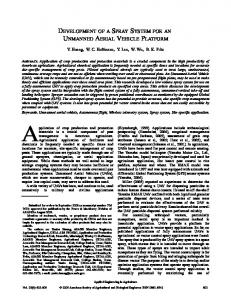
560 Fig.1. The photo of the customized UAV system for emergency investigation of single geo-hazard in the Three Gorges Reservoir Area, China.
565
Fig.2. The diagram of the architecture and main function modules of the customized UAV system.
Fig.3. The implementation process of using UAV to emergency investigate the single geo-hazard.
Fig.4. The route planning of typical regular grid pattern in plane by using Mission Planner software.
570 Fig.5. Three typical route types for UAV based emergency investigation of single geo-hazard. (a) Planar grid pattern for slightly inclined slope; (b) Vertical grid pattern for steep slope; (c) Combined grid pattern for transitional terrain.
Fig.6. The results of UAV-based emergency investigation for a slightly inclined landslide. (a) the digital orthophoto; (b) the 3D texture
575
model; (c) interpretation of the destruction.
Fig.7. The results of UAV-based emergency investigation for a dangerous rock mass on steep cliff. (a) Overview photo; (b) right side photo of the dangerous rock mass; (c) 3D texture model of the whole scene; (d) 3D texture model of the dangerous rock mass.
580
Fig.8. The results of UAV-based emergency investigation for a combined slope with transitional terrain. (a) 3D texture model and identified potential geo-hazards; (b) quantitative characteristics of the steep slope above highway.
585
590
17
Nat. Hazards Earth Syst. Sci. Discuss., doi:10.5194/nhess-2017-44, 2017 Manuscript under review for journal Nat. Hazards Earth Syst. Sci. Published: 6 February 2017 c Author(s) 2017. CC-BY 3.0 License.
595
List of Tables
Table 1. The core components and main features of the customized UAV system.
600
605
610
615
620
625
630 18
Nat. Hazards Earth Syst. Sci. Discuss., doi:10.5194/nhess-2017-44, 2017 Manuscript under review for journal Nat. Hazards Earth Syst. Sci. Published: 6 February 2017 c Author(s) 2017. CC-BY 3.0 License.
Figures
Terminal monitor
Ground control station
Aerial gimbals
Four-axis & eight-rotors carbon fiber airframe
Remote controller
Camera Fig.1. The photo of the customized UAV system for emergency investigation of single geo-hazard in the Three Gorges
635
Reservoir Area, China.
640
19
Nat. Hazards Earth Syst. Sci. Discuss., doi:10.5194/nhess-2017-44, 2017 Manuscript under review for journal Nat. Hazards Earth Syst. Sci. Published: 6 February 2017 c Author(s) 2017. CC-BY 3.0 License.
Aerial photography
Multi-rotor UAV subsystem
GPS Module
subsystem
Positioning data
Camera Command
Aerial
Control ommand
Flight control system
Control command
Real-time images On screen display(OSD) module
Remote-control Receiver
Camera
gimbals
Parametes & command
Flight state
Data transmission module
Real-time images of the superimposed state Flight state
Image delivery module Analog signal
Data transmission module Remote Controller Parametes & command
Image receiving module
Flight state
Real-time images of the superimposed state
Ground control station Flight route
Parameters
planning
setting
Command setting
Terminal monitor
Ground surveillance
Ground control subsystem
subsystem
Fig.2. The diagram of the architecture and main function modules of the customized UAV system.
20
Nat. Hazards Earth Syst. Sci. Discuss., doi:10.5194/nhess-2017-44, 2017 Manuscript under review for journal Nat. Hazards Earth Syst. Sci. Published: 6 February 2017 c Author(s) 2017. CC-BY 3.0 License.
Indoor Preparation Battery charging
System initial inspection
Preliminary route planning
Site Investigation Environmental assessment
Investigation scheme Automatic scheme
determination
Manual scheme
GCPs layout and measurement
GCPs layout and measurement
System assembly
System assembly
System full inspection
System full inspection
Manual
Detailed route planning
flight & shooting
Parameters setting
Autonomous flight & shooting
Site Fast PRocessing & Applying Photos pretreatment
Indoor Comprehensive Processing & Applying Comprehensive SfM processing and high precision results generating
Fast SfM processing and coarse
Accurate quantification and
precision results generating
display of geo-hazard
Coarse quantification and
Supporting the design of the
display of geo-hazard
detailed emergency treatment plan
Supporting the development of the preliminary emergency treatment plan
Fig.3. The implementation process of using UAV to emergency investigate the single geo-hazard.
21
Nat. Hazards Earth Syst. Sci. Discuss., doi:10.5194/nhess-2017-44, 2017 Manuscript under review for journal Nat. Hazards Earth Syst. Sci. Published: 6 February 2017 c Author(s) 2017. CC-BY 3.0 License.
Fig.4. The route planning of typical regular grid pattern in plane by using Mission Planner software.
22
Nat. Hazards Earth Syst. Sci. Discuss., doi:10.5194/nhess-2017-44, 2017 Manuscript under review for journal Nat. Hazards Earth Syst. Sci. Published: 6 February 2017 c Author(s) 2017. CC-BY 3.0 License.
(a)
(c)
(b)
Changed End
d
90°
d
Lens
60° direction
d 30°
Dangerous rock body
h
0°
Planning route Planning route
d
Planning route
0°
Start
Flying height:h
h Lens direction:0°
Distance from the slope:d
Lens direction