Feb 6, 2013 - multiple configurable cache and memory models, a dedicated I/O ...... Figure 13: Cache diffusion network (CDN) with only one processor, cache ...
MGSim—simulation tools for multi-core processor architectures M. Lankamp, R. Poss, Q. Yang, J. Fu, I. Uddin, C.R. Jesshope University of Amsterdam, The Netherlands
arXiv:1302.1390v1 [cs.AR] 6 Feb 2013
February 7, 2013 Abstract MGSim is an open source discrete event simulator for on-chip hardware components, developed at the University of Amsterdam. It is intended to be a research and teaching vehicle to study the fine-grained hardware/software interactions on many-core and hardware multithreaded processors. It includes support for core models with different instruction sets, a configurable multi-core interconnect, multiple configurable cache and memory models, a dedicated I/O subsystem, and comprehensive monitoring and interaction facilities. The default model configuration shipped with MGSim implements Microgrids, a many-core architecture with hardware concurrency management. MGSim is furthermore written mostly in C++ and uses object classes to represent chip components. It is optimized for architecture models that can be described as process networks.
Contents 1 Introduction
2
2 Context and related work
2
3 Architecture of the simulator
4
4 Component model library
11
5 Monitoring and measurements
26
6 Shortcomings and possible future work
30
7 Summary and conclusions
31
Acknowledgements
31
References
31
1
1
Introduction
MGSim is a discrete event simulator for on-chip hardware components, developed by a group of researchers at the CSA group1 at the University of Amsterdam since 2007. MGSim is developed as a research and teaching vehicle to study the fine-grained hardware/software interactions on many-core and hardware multithreaded processors. It includes support for core models with different Instruction Set Architectures (ISAs), a configurable multi-core interconnect, multiple configurable cache and memory models, a dedicated I/O subsystem, and comprehensive monitoring and interaction facilities. The default model configuration shipped with MGSim simulates the Microgrid platform, so that programmers can use MGSim as a full-system emulation of a computer equipped with a Microgrid [15]. As a software infrastructure, MGSim’s component models and simulation kernel are written in C++; they use object classes to represent the chip components. Ancillary tools are written in Python. A characteristic feature of the MGSim framework is that it promotes the definition of architecture models where components across clock domains only synchronize via FIFO buffers, i.e. where models can be described as process networks. MGSim is further available2 free of charge under an open source license. This article reviews the MGSim tool box, as of version 3.3. We start in section 2 by describing its background story and how it compares to its competitors. We then review its simulation framework in section 3, followed by its existing component models in section 4. Section 5 then shows how the user can inspect the state of the simulation. Finally, section 6 outlines possible future developments and section 7 wraps up the presentation.
2
Context and related work
2.1
Motivation and audience
Historically, MGSim was first developed to explore the behavior of D-RISC cores [3, 1] when grouped together in a many-core processor chip. Since then, MGSim has matured into a versatile framework to simulate many-core architectures. The development of MGSim is guided by two main purposes. The first is support scientific research in the design of many-core general-purpose processor architectures. So far, the implementation of MGSim has been influenced by the research activities of the CSA group at the University of Amsterdam, namely: • design space exploration of multi-processor systems-on-chip, i.e. testing different combinations of architecture parameters to optimize platforms towards specific applications, and • design of new techniques in processor micro-architecture, i.e. adding or changing features in individual processor cores and their memory interconnect to obtain higher performance/cost ratios. The other purpose of MGSim is to support undergraduate and graduate education activities in computer architecture, parallel program1 http://csa.science.uva.nl/ 2 currently
hosted at http://svp-dev.github.com/.
2
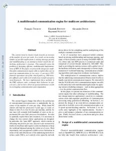
Figure 1: Emulators and simulators: a Venn diagram with examples. ming, compiler construction and operating system design. In particular, MGSim was tailored to the following requirements: • provide a human-scale software infrastructure that can be comprehended by standalone students in these fields, • integrate the emulation platform and its operating software in a software package that can be seamlessly deployed and get ready to run on student computers with minimal effort, • provide interfaces to observe and illustrate the internal workings of a system while it is running.
2.2
Emulation vs. simulation
MGSim can be considered both as a simulation framework and a full-system emulator. Simulators are tools that reproduce abstract models of component behaviors, often to make predictions about them. Simulators are key items in the toolbox of hardware architects, who need to explore the behavior of computing components before their design is finalized, using pre-selected software benchmarks. Emulators are tools that reproduce the concrete behavior of a computing artifact, including the hardware/software interface of a given processor. Emulators are used, for example, during compiler and operating system development, to debug software in a controlled environment before it ships to production. In short, simulators exist to debug and optimize hardware designs, whereas emulators exist to debug and optimize software running on the emulated system. Emulators can be further divided between partial and full system emulation (also called “virtualization”). With partial emulation, only application code runs within the emulation environment, and operating system functions are serviced through a host/guest interface. With a full emulation, the entire software stack runs on the emulated hardware. MGSim can serve both as a hardware simulator and full-system emulator. We illustrate these distinctions in fig. 1.
2.3
Related work
In the group of software frameworks that are both simulators and emulators, as illustrated above, MGSim most relates to SimpleScalar3 and Gem54 [2]. 3 http://simplescalar.com/ 4 http://m5sim.org
3
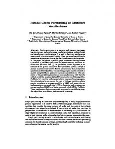
Figure 2: Entity-relationship diagram of an MGSim simulator. In contrast to MGSim, SimpleScalar only provide partial emulation: operating system functions are served on the host platform via the syscall pseudoinstruction. MGSim was designed as a full-system emulation so as to also study the behavior of operating software when running over the emulated platform. Moreover, SimpleScalar was primarily designed to emulate single-core platforms, where MGSim’s focus lies towards multi-core platforms. Its purpose and even its software architecture make MGSim much closer to the Gem5 framework. Gem5, like MGSim, consists of a library of C++ components that can be grouped in configurable topologies to define multi-core platforms. Both frameworks are discrete event, component-based simulations able to emulate full systems. At the time of this writing, Gem5 even offers more monitoring and visualization facilities than MGSim. The differences between Gem5 and MGSim can be found at two levels. Firstly, Gem5 was designed and motivated to emulate existing platforms. In particular, one of its design requirements was to be able to run entire existing software stacks unchanged, for example GNU/Linux, FreeBSD, L4K or Solaris. MGSim does not share this requirement, and its implementation is thus much simpler than Gem5’s. This makes MGSim more accessible for education activities than Gem5. Secondly, Gem5 started as a single-core system emulator, focusing on the accurate simulation of large, state-of-the-art sequential processors. Multi-core support was only added later, and Gem5 is still optimized for use with few cores sharing a high-level functional emulation of a cache coherency network and interprocessor interrupt network. In contrast, MGSim was designed from the groundup as a many-core network featuring different detailed memory interconnects and a dedicated point-to-point messaging network between cores. This makes MGSim a potentially more productive tool for research in operating software for fine-grained multi-core applications.
3
Architecture of the simulator
MGSim’s framework is composed of five main parts, illustrated in fig. 2. The simulation kernel provides base abstractions for processes, registers,
4
1. 2. 3. 4. 5. 6. 7. 8. 9. 10. 11.
Front-end main() ↔Config::Config()
Configuration
Components
→MGSystem::MGSystem()
↔∀C.C::C()
→HandleCommandLine() ,→cmd_run() ,→StepSystem()
Kernel
→Kernel::Step() ↔ ∀S.S::Update() ∀P.P ::CycleHandler (Aq)↔ ↔ ∀A.A::OnArbitrate() ∀P.P ::CycleHandler (Ck)↔ ∀P.P ::CycleHandler (Ct)↔
Table 1: Call graph of MGSim’s initialization and first simulation cycle. buffers, latches, arbitrators and ports, as well as an execution driver that schedules ready component processes at each simulation cycle. The library of component models provides object classes for the various component types found on the chip: processors (cores), caches, memory networks, I/O interconnects, etc. The component models are implemented using the base abstractions from the simulation kernel. Typically, a component will define one or more processes, optionally some internal state for its processes, and latches, buffers and/or arbitrators visible from other components. The system configuration constructor instantiates the component models and connects them together to form a full architecture model. This part is further distributed between a top-level “system topology” constructor and the individual constructors of component models, which may choose to instantiate sub-components or dependent components. The simulation front-end provides a user interface to MGSim. The interface is composed of command-line parsing, configuration file loader, interactive command interpreter, event trace filtering, asynchronous monitoring, etc. Finally, the optional asynchronous monitor runs asynchronously in a separate thread of execution. It periodically samples the state of selected components and writes it to a trace file or FIFO for analysis or visualization by external tools. See section 5 for details.
3.1
Simulation overview
Table 1 provides a step-by-step overview of the initialization of MGSim and the handling of one simulation step. Upon initialization of an MGSim instance, the front-end parses the commandline parameters and configuration file(s) (step 1). It then creates a Config object that holds a database of configuration variables (step 2). The front-end then instantiates the configuration constructor (MGSystem) which in turn populates the architecture model by instantiating components according to the configuration (step 3). After this point the model is ready, no further objects are constructed, and the simulation can start. If invoked to run interactively, the front-end displays an interactive prompt and accepts user commands (step 4). For example, invoking the run command starts the simulation by triggering the Step method of the simulation kernel (steps 5 & 6). Step can advance the simulation by one or more cycles. At every cycle, the following happens: 7. Any pending updates to stateful structures shared by components (e.g. FIFO
5
buffers) are committed, to become visible during the new cycle. 8. The acquire phase of the cycle is run for all active component processes. During the acquire phase, process handlers declare their intent to use shared structures and request arbitration. During this phase, processes may not update internal state. 9. After the acquire phase completes, all involved arbitration requests are resolved by the kernel. 10. Once arbitration has been resolved, all active processes run the check phase of the cycle. During this phase, the results of arbitration is reported to each process, which determines which control path to use (e.g. stall, access another shared storage, etc.). Again, during this phase, processes may not update internal state. 11. Once the check phase has completed, all remaining non-blocked processes run the commit phase of the cycle. During this phase, processes use the control path chosen during the check phase, may update their internal state, and declare updates to shared storage to be effected at the start of the next cycle. They may also emit informational messages to be logged to a synchronous event trace by the kernel. At the end of each cycle, active processes are then rescheduled to run at the next cycle or some cycles later, according to their simulated clock frequency. Note that during the check phase, processes may become blocked because of denied arbitration, but also when attempting to read from empty FIFOs. When a process becomes idle on an empty input FIFO, it will thus only be reactivated after a subsequent cycle produces data into the FIFO. This is the mechanism by which MGSim models the behavior of asynchronous networks of components.
3.2
Anatomy of a component
Components in the simulation framework are intended to correspond roughly to components on chip, i.e. to an area of hardware. They are organized in a tree, where each child node represents a sub-parts of its parent component. For example, the DCache (L1 data cache) and Pipeline components are child nodes of the processor component (Processor) which encompasses them. The base interface for all components is Object. Via Object, each component is related to: • a name that identifies it relative to its siblings in the tree; • its parent component and children components, if any; • a clock domain (either its own or shared with its parent); • the simulation kernel that drives the entire component tree. Additionally, each component may define one or more of the following: • processes, which represent state machines or functional circuits; • shared storages and arbitrators, e.g. FIFO buffers, registers or single-bit latches, which may be used by two or more processes including processes from other components, and which may cause processes to block upon access; • internal state used by only one process, or state shared by processes of the same component that does not require arbitration nor decides process scheduling; • services, which provide part of the logic of processes from other components; 6
• inspection handlers, which are invoked from MGSim’s interactive command prompt upon user commands, • administrative data for the simulator itself which does not represent hardware components (e.g. counters for statistics). We can illustrate these concepts using the ICache component which models an L1 instruction cache. This defines, for example: • the two processes p_Outgoing and p_Incoming for the input and output queuing from and to memory, respectively; • the two buffers m_outgoing and m_incoming shared with the memory subsystem, which may control the scheduling of p_Outgoing/p_Incoming; • the internal state m_lines which represents the cache’s data blocks, protected against concurrent accesses by the shared arbitrator p_service; • the service Fetch, used by the pipeline process of the same name and which writes to m_outgoing, and the service OnMemoryReadCompleted, used by the connected memory process upon completion of loads and which writes to m_incoming; • an administrative reference m_memory to the simulation component in charge of simulating the memory system; • the administrative counter m_numHits used to generate cache statistics.
3.3
Component processes
Processes in the simulation framework represent the activities of data transformation and communication in the system. All processes are triggered by the availability of data in a specific shared storage, which we will call its source storage. When triggered, a process becomes active and its cycle handler is called by the kernel at every cycle of the corresponding clock domain. The process’ cycle handler may then in turn attempt to acquire more storage or arbitrators, fail while doing so and thus stall. When stalled, the cycle handler will re-try the same behavior in subsequent cycles until the behavior succeeds. Upon successful completion, a process may either consume data from its source storage or stay ready to be invoked again for another behavior in the next cycle (e.g. in state machines). A process becomes idle when its source storage becomes empty. The base interface for all processes is Process. Via Process, each process is related to: • its enclosing component; • a name that identifies it within the enclosing component; • its state (running/stalled or idle); • its cycle handler invoked at every cycle of the clock domain while running or stalled. We can illustrate these concepts using the Outgoing process of the ICache component. This process is triggered by the m_outgoing FIFO buffer, which is populated with refill requests by the pipeline’s fetch stage upon I-cache misses. The Outgoing process is in charge of picking the front-most request at each cycle and sending it to the memory system. Its (simplified) handler is given in listing 1. The behavior is to try to issue a memory load via the service m_memory.Read(). If the service is unsuccessful (e.g. due to memory contention), the handler in turn reports failure to the kernel, which will cause the kernel to stall the process. When stalled, Outgoing handler will be called again 7
1 2 3 4 5 6 7 8 9 10 11
R e s u l t ICache : : DoOutgoing ( ) { auto& a d d r e s s = m_outgoing . Front ( ) ; i f ( ! m_memory . Read ( a d d r e s s ) ) { DeadlockWrite ( " Unable ␣ t o ␣ r e a d " ) ; return FAILED ; } m_outgoing . Pop ( ) ; return SUCCESS ; }
Listing 1: Behavior of the ICache’s Outgoing process.
1 2 3 4
R e s u l t ICache : : DoIncoming ( ) { i f ( ! p _ s e r v i c e . Invo ke ( ) ) return FAILED ;
5
auto l i n e i d = m_incoming . Front ( ) ; COMMIT{ m_lines [ l i n e i d ] . s t a t e = LINE_FULL ; } // . . . m_incoming . Pop ( ) ; return SUCCESS ;
6 7 8 9 10 11
}
Listing 2: Simplified behavior of ICache’s Incoming process.
at its next cycle. If the request can be issued to memory, the handler then consumes the entry with m_outgoing.Pop() and reports success. If m_outgoing becomes empty as a result, the Outgoing is then marked idle by the kernel. The macro DeadlockWrite registers a message that is only printed by the kernel if all processes in the system become stalled, which would be a sign of deadlock. Process instantiation occurs as part of the enclosing component’s instantiation. During instantiation, the component’s constructor will gives a name to the process and declares the process and its cycle handler to the simulation kernel. The cycle handler is typically implemented as a C++ method in the enclosing component, for example ICache::DoOutgoing() in this example. Two additional features can be found in the handler of ICache’s other process Incoming, given in listing 2. This process is triggered by m_incoming, a FIFO buffer populated by memory load completion messages coming from memory, i.e. refill data after cache misses. Because this handler accesses the internal cache state m_lines, it must first acquire the arbitrator p_service which protects the line data against access races with the pipeline’s fetch stage (the Fetch service also acquires p_service). Arbitrator acquisition occurs in two phases. During the acquire phase of the cycle, the handler sees the Invoke method always succeed. However, during that phase Invoke also registers the arbitration request. After the acquire phase completes, the kernel resolves arbitrations and marks processes for which
8
arbitration fails. Then the process handler is run again during the check phase of the cycle, and Invoke returns true or false depending on the arbitration results. Note that the entirety of the handler executes during the acquire phase “as if” arbitration had succeeded already. However, internal component state must not be modified at this phase, since the process may be arbitrated away for this cycle as a result. Therefore, any update to internal state, like m_lines in the example above, must be enclosed in a COMMIT block which is only performed during the phase of the same name in the cycle. Accesses to shared storages via Push and Pop is already internally handled via a COMMIT block and thus do not need the extra marking in process handlers. The execution of process handlers in three phases and the use of COMMIT blocks for state updates is the fundamental mechanism through which MGSim achieves transactions in components.
3.4
Shared storage
Shared storage is a basic abstractions of the simulation kernel that represent state visible to one or more processes, with controlled update semantics: • processes updating the storage must be in the same clock domain; • if linked as a source storage to a process, the storage will activate the process when non-empty; • multiple updates in the same cycle are rejected (a form of arbitration) unless explicitly allowed by the storage model. The following sub-types of storage are provided: • Buffer: a FIFO buffer with accessors Push, Pop, Front; • Register: a full/empty storage cell with accessors Read, Write, Clear, Empty; • SingleFlag: a single bit trigger with accessors Set, Clear, IsSet. Of these, Buffer is the only model that supports multiple updates in the same cycle, up to a maximum set during instantiation. This reflects the ability of most FIFO circuits to process FIFO appends faster than the cycle time of their client processes.
3.5
Arbitrated services and ports
When two or more processes must synchronize their access to a shared storage or some component’s internal state, arbitration is required. For this MGSim provides two abstractions. The first abstraction, arbitrated services, model standalone arbitration circuits, independent from the storage or state that they protect. They are loosely analogous to the concept of “mutex lock” in concurrent programming languages; when they grant access to a process, the process’s handler can perform multiple updates to the protected state atomically. For example, the arbitrator p_service in ICache discussed previously is an arbitrated service, protecting the internal state m_lines from concurrent access by the Fetch service and Incoming process. The second abstraction, arbitrated ports, model arbitration circuits combined with a storage structure with multiple entries, for example a register file. Arbitrated ports arbitrate on each entry of the structure separately, depending 9
on the index requested. This way, two accesses in the same cycle to different indices do not cause their respective processes to stall; whereas two accesses to the same index causes one of the processes to stall due to arbitration. As of this writing, arbitrated ports are only used for the register files of the core model Processor; other shared storage and state is modeled as a single entity and thus only require the protection offered by arbitrated services, which is cheaper to simulate. Furthermore, both arbitrated services and ports are parameterized with an arbitration strategy, which models which arbitration circuit to use. The following arbitrators are available: • priority arbitrators: multiple processes are connected at fixed priorities; during a cycle, the process with the highest priority is granted access. This is the simplest and cheapest arbitrator in hardware, but the priorities must be chosen carefully to avoid starvation and priority inversion. • cyclic arbitrators: multiple processes are connected at equal priority; during a cycle, a counter is incremented and grants access in a round-robin fashion. This is slightly more expensive to implement in hardware, however it guarantees fairness. • priority-cyclic arbitrators: akin to a priority arbitrator, with the lowest priority level shared by multiple processes using a cyclic arbitrator. This is the most expensive arbitrator to implement in hardware.
3.6
Termination and deadlock detection
Since processes are only activated when shared storage is updated, and shared storage is updated only by other processes, a situation where all processes in the system become idle corresponds to a system where there is nothing more to do, i.e. a halted machine. This situation is recognized by MGSim’s kernel and terminates the simulation without error. Meanwhile, since MGSim is intended for use in architecture research, a situation can occur where the architecture model contains errors which cause the system to deadlock. In particular, two or more processes may be erroneously defined to mutually wait on each other by competing for access to a cyclical chain of shared storages. As per section 3.3 above, active processes waiting on arbitration declare themselves to MGSim’s kernel as stalled. Therefore, if the kernel detects during a cycle that all non-idle processes have become stalled, it can conclude that a deadlock has occurred and terminate the simulation with a deadlock error. Moreover, each individual cycle handler that marks its process as stalling may register a “deadlock message” for the kernel with DeadlockWrite. Upon detecting a deadlock, the kernel replays all involved cycle handlers to actually print the deadlock messages, so that the user can investigate the situation. Intuitively, these mechanisms are limited in two situations: • when a livelock occurs, the livelocked processes appear to MGSim’s kernel as if they were making progress (they are non-idle and non-stalled), and the situation cannot be detected. It is expected that this form of error is handled at the software level running on the simulated platform by means of timeouts. • when the simulated platform is waiting on external input, the corresponding process in the simulated input device marks itself as running (i.e. not 10
idle and not stalled) until external input is received. If a deadlock occurs in the rest of the system during that time, MGSim’s kernel is then unable to detect it. For this reason, all simulated I/O devices provide the concept of “activation,” whereby the input process is only running when the device is activated. Activation/deactivation is then requested explicitly by system software running on the simulated platform during input operations, to minimize the amount of time where deadlock detection is disabled.
3.7
Contracts with the implementer
The abstractions provided by MGSim’s kernel model circuits templates that are known to be constructable in hardware. However, the implementer of components for MGSim may fall victim to three pitfalls which are not protected against by the MGSim framework. The first pitfall was mentioned above; it is the ability to define a deadlocking architecture. This can happen when a group of two or more processes are directly or indirectly waiting for each other via a cyclical arbitration chain. To avoid this pitfall requires analysis of the process dependency graph and thorough testing of modeled designs. The second pitfall is the ability to express a cycle handler for a process that is not implementable in hardware. As of this writing, MGSim does not restrict which part of the C++ language can be used in a process handler. It is thus possible to erroneously use the full generality of the language, and define a behavior that has potentially unbounded space and time requirements. To avoid this pitfall requires checking via code analysis that the expressed computations correspond to primitive recursive functions with existing equivalent circuit implementations. The third pitfall is the ability to configure a simulated clock frequency incompatible with the length of the critical path through the circuit implementing a process cycle handler. Indeed, any cycle handler definition corresponds to some minimum complexity in hardware. This complexity in turn places a lower bound on the duration of a clock cycle, at a given silicon technology and energy supply. MGSim does not prevent the implementer or user from defining a simulated clock frequency with a smaller cycle duration than required by the hardware circuit. To avoid this pitfall requires expert knowledge about the relationship between the circuit specification in a cycle handler, the circuit complexity in hardware, and the relationship between energy, gate density, critical path length and frequency for the envisioned silicon technology. This last pitfall is shared by most simulation frameworks that simulate at a level higher than individual circuit gates. The first two pitfalls may be partially prevented in the future by automated solutions, cf. section 6 for details.
4
Component model library
MGSim is shipped with a set of predefined component models and a predefined, configurable system topology. The preset library further contains three component categories: processors, I/O devices and interconnect, and memory systems.
11
Figure 3: Overview of Processor and its sub-components.
4.1
Processor/core models
The MGSim library provides two predefined processor models: Processor and FPU. They are separate since one FPU can be shared by two or more processors. The Processor model implements a simple processor core with an in-order, single-issue, six-stage RISC pipeline. An overview of its sub-components is given in fig. 3. As of this writing, the model can emulate a subset of either the DEC Alpha ISA (64-bit, little endian), the SPARCv8 ISA (32-bit, big endian) or the MIPS I ISA (32-bit, either little or big endian). All ISAs are emulated on top of the same six pipeline stages, albeit with different data paths and stage behavior. For example, the SPARC model consumes two cycles in the read stage for a “store double” (std) instruction to read its three register operands over the two read ports to the register file, and consumes also two cycles in the memory stage for double loads and stores. In addition to the base pipeline behavior, the Processor model also provides out-of-order completion for some instruction types using dynamic dataflow scheduling. This is done by equipping the register file with full/empty bits on each register, and marking the output operand of long-latency instructions to be “pending”. When a subsequent instruction reads from a “pending” input, it is scheduled to wait until the operand becomes available, i.e. until the original instruction completes. This feature enables latency tolerance, as e.g. loads to missing L1 cache lines do not stall the pipeline, and independent subsequent instructions can continue to execute. This is a feature provided by the DRISC model that Processor was originally designed to simulate. Details about the dynamic scheduling abilities of D-RISC are detailed in [11, 15, 12] and [9, Chap. 3]. Furthermore, the Processor model can also simulate hardware multithreading, up to a configurable number of hardware threads. This feature is also inherited from the D-RISC model that Processor was designed to simulate. The hardware scheduling is similar to the one found in the Niagara [10] architecture, although MGSim’s Processor can also preemptively switch threads at
12
Figure 4: External interfaces of the predefined Processor model. the fetch stage if an instruction is known in advance to possibly miss its input dependency. Like Niagara, it provides 0-cycle switch overhead. The Processor model supports the following external interfaces, illustrated in fig. 4: • an interface to an instance of FPU, which may be shared with other processors. The interface is bidirectional and asynchronous: FP operations are dispatched in-order by Processor to the appropriate queue/pipeline on the FPU, but may complete out of order. • an interface to a memory system via its L1 data and instruction caches. If supported by the memory system, Processor can issue multiple requests before waiting for an answer, and even communicate bidirectionally. • an interface to a control network-on-chip (NoC), which may be separate from the memory system. Through this network, Processor can receive messages that influence its hardware threads or remotely access its registers via a dedicated Thread Management Unit (TMU) in hardware. From its D-RISC heritage, Processor also provides ISA extensions to send messages over this NoC, described in [9, Chap.4 & App. D]. • optionally, an interface to an I/O NoC, which may be separate from the two previous networks. When enabled, Processor simulates a memorymapped interface at the memory stage of the pipeline to send and receive messages directly to/from I/O devices via this NoC. It also simulates an integrated Direct Memory Access (DMA) controller able to convert I/O messages from the NoC to memory requests without participation from the main pipeline. • administrative interfaces for inspection and debugging by the user of the MGSim framework. At the time of this writing, the choice of ISA to be emulated by Processor is static: a compiled MGSim instance can either support an Alpha ISA, or a SPARC ISA, etc., but not both in the same simulator executable. This choice was made to enable compile-time optimizations around important architectural constants, namely: the width of a data word, the width of memory addresses and data endianness. Most other architectural parameters are configurable upon MGSim’s initialization at run-time, including L1 cache sizes/associativity/indexing, the core’s clock frequency, FPU-core mappings, the availability of an
13
Figure 5: Serial memory model (SerialMemory) with one processor.
Figure 6: Serial memory model in a multi-core configuration. I/O interface and the buffer sizes of the memory/NoC interfaces.
4.2
Memory models
The MGSim library provides multiple memory systems to connect processor cores to external memory. The existence of several memory models side-byside is motivated by ongoing scientific research in multi-core architectures: for evaluation, practitioners typically find it useful to perform comparative analyses of the behavior of multi-core systems using different memory architectures and system topologies. Although MGSim’s framework does not limit the applicability of each model, not all combinations of memory models and number of cores are accurate and useful. The complexity of the hardware circuits corresponding to some models grows unfavorably with the number of cores, suggesting to switch to another memory architecture instead. Moreover, as outlined in section 3.7, the user should care to align the frequency of the memory clock domain according to the expected hardware complexity of the chosen configuration. At the time of this writing, MGSim’s framework does not contain logic to automatically scale frequency to circuit complexity nor report unrealistic/unimplementable configurations; expert knowledge by the user is expected to apply. 4.2.1
Serial memory
The simplest memory model is SerialMemory, illustrated in figs. 5 and 6. In a single-core configuration, load and store requests from the processor are queued in a buffer (16 entries by default) and handled one after another by a request handler process, which simulates a memory controller. The latency to
14
Figure 7: Parallel memory model (ParallelMemory) in a multi-core configuration. handle each request is configurable. The responses are served directly to the processor by the request handler. In a multi-core configuration, the components do not change but an MGSim arbitrated service controls access to the request buffer, thereby simulating a request bus between all processors. Responses to requests are served directly to the processor that initiated the request using a separate bus without arbitration (as there is only a single initiator). Write requests snoop on the L1 cache of all other processors on the bus (i.e. after being granted access by the arbitrator). The memory systems that this model simulates are highly sensitive to contention on the request bus, and thus rarely used practice with more than 4-8 cores. The front-end configuration key MemoryType can be set to SERIAL to automatically build a memory system of this type. 4.2.2
Parallel memory
MGSim’s ParallelMemory model is identical to SerialMemory in a single-core configuration, but differs in a multi-core configuration as illustrated in fig. 7. Here, each processor has its own port to the memory, implemented as its own request queue and handler. Thanks to this independence, there is no contention between separate cores. Write requests snoop on the L1 cache of all other processors transparently (i.e. snoop contention is not simulated). This model is intended to represent an ideal parallel memory. It can be used e.g. to study the theoretical bounds on throughput and latency when contention is not considered. It is not intended to be an accurate model of hardware; a hardware implementation would require either an arbitrator between the request handlers to access the physical memory array, or to bank the memory and use one arbitrated port per bank. The front-end configuration key MemoryType can be set to PARALLEL to automatically build a memory system of this type. 4.2.3
Banked memory in a single-core configuration
Two predefined models are provided that offer memory-level parallelism by separating requests to different memory banks: BankedMemory (fig. 8) and DDRMemory (fig. 9). The former uses a sequential request handler like SerialMemory 15
Figure 8: Banked memory model (BankedMemory).
Figure 9: Banked memory model with DDR3 controllers (DDRMemory). above, whereas the latter uses a simulation of a DDR3 channel controller. The DDR3 protocol provides additional parallelism by overlapping the handling of subsequent requests in a pipeline. In both models, the number of banks is configurable. The selection of which bank or DDR channel to use is made for each request coming from the processor based on the memory address. The request is then queued at the selected bank/channel, processed asynchronously, and the response is then queued for delivery. Responses from different banks/channels to the same processor are delivered using an arbitrated service, i.e. at most once per memory clock cycle. These models are intended to simulate hardware memory systems where one processor is connected to multiple memory modules via a bidirectional bus. 4.2.4
Address to bank mappings
Which selection strategy is used to select banks/channels is also configurable. MGSim’s component library provides the following: • ZeroSelector: always select the first bank/channel (used for troubleshooting); • DirectSelector, DirectSelectorBinary: uses the lowest order bits of the address as bank index; • RightXOR, RightAdd: computes the bank/channel index using an exclusive binary OR (for RightXOR) or sum (for RightAdd) of two low order blocks
16
Figure 10: Banked memory model in a multi-core configuration. of index-sized bits in the address, as per [6]; • XORFold, AddFold: generalization of RightXOR/RightAdd to all bits of the address; • RotationMix4: compute a four-step, rotation-based hash of the address and use the low-order bits of the hash to select a bank/channel. DirectSelectorBinary models the most common circuits in hardware, but is sensitive to strided memory accesses that align with the number of banks: these would cause contention on a single bank. The model RotationMix4 provides near-ideal randomization of the address to bank mapping and can be thus considered to simulate near-ideal load distribution. Its higher circuit complexity makes it an unlikely hardware implementation, though. Four predefined settings are recognized by the front-end for configuration key MemoryType: • BANKED: BankedMemory with either the DirectSelector or DirectSelectorBinary strategy, depending on the number of banks configured (the latter is used when the number of banks is a power of two); • RANDOMBANKED: BankedMemory with the RotationMix4 strategy; • DDR: DDRmemory with either the DirectSelector or DirectSelectorBinary strategy, depending on the number of DDR channels configured; • RANDOMDDR: DDRMemory with the RotationMix4 strategy. 4.2.5
Banked memory in a multi-core configuration
Both BankedMemory and DDRMemory generalize to multi-core configurations as shown in fig. 10 and fig. 11. When used with multiple processors, each processor receives its own bank selection circuit. Requests coming from a processor are then queued to their selected bank/channel using an arbitrated service, to appropriately simulate contention at the bank/channel. Responses are then delivered directly to the processor that issued them using one arbitrator per core, as if each bank/channel controller had direct point-to-point response links to all processors. Write requests snoop on the L1 cache of all other processors transparently (i.e. snoop contention is not simulated). The number of processors and the number of banks are independent, i.e. can be configured separately. If only the number of processors is specified, the
17
Figure 11: Banked memory model with DDR3 controllers in a multi-core configuration. number of banks is automatically scaled to be the same. This multi-core generalization of the two models is intended to simulate a memory circuit in hardware with a crossbar switch or multistage interconnection network between processors and memory banks/channels, such as found on the Niagara chip. The hardware and energy costs of these circuits usually prevent their practical use with more than 16-32 cores.
4.3
Ring-based cache diffusion networks
An ongoing research project at the University of Amsterdam aims to design a novel memory system based on a scalable network of caches. The latest outcome of this research is also provided as memory models in MGSim’s library of predefined components. There are two families of models, referred to as “COMA” and “ZLCOMA” in MGSim’s source code. Their use of the acronym “COMA” is due to historical ties between this research and related work on Cache-Only Memory Architectures in the 1990’s [7, 4]. In the original COMA vision from the 1990’s, DRAM banks in the system are managed as a network of very large caches. The key characteristic is that the partitioning of the address space among the memories is not static: directories at each memory retain an index of which addresses can be currently found at the memory. A protocol between the memories ensures that all addresses are present somewhere in the network. The corresponding key feature is that the blocks of data corresponding to the most frequently used addresses can be migrated to the part of the system where they are most frequently used. Because of this feature, each memory in the system is also called attraction memory (AM). However, the memory architecture modeled in MGSim’s library has diverged from the original COMA concept. The reason is that it is difficult to fit the entire DRAM storage of a system onto a single chip, and off-chip COMA caches and directories are difficult to manage at the latency and bandwidth scales required by on-chip parallelism. Instead, the memory architecture designed at the University of Amsterdam still uses static partitioning of the address space across memory banks, but uses a distributed network of caches on chip with a similar attraction property as a COMA: cache lines fetched once in the
18
(a) Uniform Memory Architecture (UMA)
(b) Memory (NUMA)
Non-Uniform Architecture
(c) Cache-Only Memory Architecture (COMA)
(d) Cache Diffusion Memory Architecture (CDMA)
Figure 12: Overview of differences between memory architectures. cache network tend to stay within the network, so as to avoid off-chip memory accesses as much as possible. Moreover, a cache miss in one part of the network is resolved by fetching data from another part if it can be found, instead of fetching from external memory. As with a COMA, on-chip directories remember which addresses can be currently found within the on-chip cache network. Because of this difference with COMAs, the memory architecture modeled in MGSim would be best described as a cache diffusion memory architecture (CDMA), based on attraction caches (AC) and a cache diffusion network (CDN). We summarize the difference between the more conventional uniform and non-uniform memory architectures, COMAs and CDMAs in fig. 12. 4.3.1
“COMA” vs. “ZLCOMA”
As mentioned initially, MGSim’s library provides two CDMA models called “COMA” and “ZLCOMA.” Both use the same topology (layout) of caches, directories and network links, presented in the following sections. The model “ZLCOMA” was historically implemented first, and corresponds to the token-based, write-invalidate cache protocol published in [16, 5]. Its design strives to minimize communication across the cache network. Unfortunately, this protocol currently relies on complex metadata updates at the caches and directories, which makes its implementation in hardware relatively expensive; moreover its weak consistency model violates the expectations of shared memory programming. These limitations have motivated the design of an alternate, simpler, writeupdate cache protocol over the same component topology. The “COMA” model uses this simpler protocol. Because it uses write updates messages to signal memory loads to lines duplicated in other caches (instead of requesting first exclusivity by forcing other caches to evict their copy, as with “ZLCOMA”), this protocol suffers from high bandwidth contention for write-heavy workloads with poor cache locality. Both protocols are research projects of the CSA group at the University of Amsterdam. Although they are not known to be used in existing hardware products at the time of this writing, their models and default configuration in MGSim’s library strives to reflect a realistic potential hardware implementation in a future chip.
19
Figure 13: Cache diffusion network (CDN) with only one processor, cache and external channel. 4.3.2
Components in a cache diffusion network
The simplest configuration of the CDMA models is depicted in fig. 13. The processor is connected via its memory interface to an attraction cache, which thus acts as its second level (L2) cache. The model for a single attraction cache is called Cache in MGSim’s framework. The attraction cache is then connected to a root directory via a ring network (green links in the picture), with which it organizes its distribution of cache lines. The model for a root directory is called RootDirectory in MGSim. The root directory is in turn connected to main memory via a DDR3 controller, using the same DDR3 channel simulation as the DDRMemory model discussed earlier in section 4.2.3. At a given topology, the main configurable parameters of the model define the structure of attraction caches: • the cache size, via the number of sets and set associativity; • the strategy to map memory addresses to cache set indices, using the same selector options as in section 4.2.4. Besides the cache structure, the clock frequency of the components can be adjusted, as well as the number of buffers for each network link. The number of directory entries in RootDirectory is further automatically configured based on the cache parameters and the number of caches in the network. At the time of this writing, the default configuration of both the COMA and ZLCOMA models in MGSim’s library defines 4-way associative, 128KiB attraction caches with the XORFold set selection strategy. Each link buffer has space for 2 requests, and the entire cache network up to but excluding DDR3 channels is clocked at 1GHz. 4.3.3
CDMA topologies
All component models in MGSim’s library are accompanied with configuration code to instantiate component models and connect them together to form an actual architecture. To simplify configuration, MGSim provides parameterized topologies: component and architecture constructors that automatically connect components together according to a general skeleton, based on few parameters, such a the desired number of components of each type. There are two proposed network topologies for CDMAs: a single ring and stacked rings. Reference configuration code is provided with the CDMA models in the MGSim library. Each constructor is parameterized by the desired number of components of each type, and automatically instantiate components and connect them in ring networks. With a simple ring, both the number of attraction caches and the number of root directories can be configured separately. As both counts grow, the com20
Figure 14: Single-ring CDMA with three attraction caches and one directory.
Figure 15: Single-ring CDMA with one attraction cache and three directories. ponents are automatically organized as depicted in figs. 14 to 16. When both multiple attraction caches and multiple root directories are configured, the components are automatically interleaved in the ring network, so as to minimize the average latency of requests. The ability to define multiple root directories provides memory parallelism. As of this writing, the memory address space is striped over the available backend memories at the granularity of single cache lines, so as to maximize load distribution of requests. The other provided topology skeleton uses stacked rings: cluster of attraction caches are grouped into local rings, and all rings are connected together in a top-level ring containing the root directories to external memory. An example is given in fig. 17. The motivation behind stacked rings is to exploit locality. Indeed, a multicore computation may require a lot of cache line movements between its cores, but may be relatively independent from the memory activity of the rest of the system. In this case, it is desirable to segregate its network activity physically, so as to avoid influencing negatively the bandwidth available to the rest of the system. This is the service offered by the local rings in CDMAs: local intercache traffic within the local ring stays mostly independent from the traffic from other local rings. With stacked rings, the connection point between local rings and the toplevel ring is a partial directory (modeled by the Directory component in MGSim), which only inventory the lines present in the local ring. As with the single-ring topology, partial and root directories are interleaved in the top-level ring, and partial directories are sized automatically based on the configuration of the local attraction caches.
21
Figure 16: Single-ring CDMA with three attraction caches and three directories.
Figure 17: Stacked-ring CDMA with six attraction caches and two root directories. 4.3.4
Shared attraction caches
Another dimension of parallelism can be obtained by sharing one attraction cache between multiple processors, as illustrated in fig. 18. This type of configuration uses the same communication model between the processors and the shared cache as the serial memory model presented in section 4.2.1: a request bus is used to arbitrate simultaneous requests by different processors, and responses are served using a separate response bus. Also, as with the serial memory, this type of sharing is subject to contention on the request bus. 4.3.5
Summary of configuration parameters
The following parameters guide the instantiation of MGSim’s CDMA models: • whether to use a single ring or stacked rings; • the number of sets and set associativity of the attraction caches; • the number of root directories; • the total number of processors; • the number of processors per attraction cache; • the buffer sizes for the ring networks’ links; • the clock frequency of the memory components; • for stacked rings, the number of attraction caches in a local ring.
22
Figure 18: Simple CDN with a shared attraction cache. The number of attraction caches, as well as the number of local rings for stacked ring topologies, are computed automatically based on the other configuration settings.
4.4
Simulated I/O devices
The MGSim library provides pseudo I/O devices to interface simulated systems with the simulation environment. All the provided devices use the same interface, which assumes a network-on-chip with request/response packet-based communication (i.e. the primary interface is not a bus). Additionally, the library also defines an example dedicated network-on-chip that connects I/O devices and processor cores together. This model separates I/O from memory operations to separate (logical) networks; this choice was made to enable separate study of memory-related and I/O-related traffic in the initial applications of MGSim. The overall design of the I/O system and its motivations have been published in [14]. 4.4.1
Real time clock
A RTC pseudo-device is provided; it gives access to real time to simulated systems. Two operation modes are supported: • read requests can query the current time; • write requests can configure asynchronous timer events which are delivered on-time over the I/O network. The latter facility can be exploited at the processor core interface to trigger periodic processing. 4.4.2
Console pseudo-devices
Three pseudo-devices are provided to interface with the user. UART implements a serial line, using a subset of the standard NS/PC166505 programming interface. On the simulation host, the serial line can be connected either to the terminal, to a file, or to a Unix FIFO towards other processes. LCD implements a character matrix display. It has two programming modes: a memory array where each index corresponds to a character on display; and a serial byte-oriented interface which automatically implements newlines and 5 http://www.national.com/ds/PC/PC16550D.pdf
23
scrolling. On the simulation host the display is rendered on the operator’s text terminal. Display implements a pixel-oriented display. It supports its own video memory of configurable size, which serves as frame buffer. It also supports palette (indexed) and “true” (RGB) color modes. On the simulation host the display is rendered using a graphical display. 4.4.3
Interface to the host file system
The pseudo-device RPC implements a virtual file system server. It is operated using a remote procedure call protocol. Using I/O read and write requests to the pseudo-device, the simulated system can perform calls to standard filesystem operations in the host environment: open, read, write, etc. This facility was designed to enable benchmarks that need large input/output data files to feed compute-intensive algorithms, where the focus was to evaluate the computation part. By providing direct access through a RPC interface, the simulation can bypass the overhead of full operating system simulation. 4.4.4
Read-only memory with DMA controller
The pseudo-device ActiveROM implements a combination of a read-only memory (ROM) with a DMA controller. The main use of this device is to provide access to the content of specific files on the simulation host, for example the executable code of a benchmark program. Two additional options are also available: automatic initialization to the set of Unix environment variables, and to the list of command-line arguments; this facilitates the execution of multiple simulations across ranges of software parameters provided externally. As expected, the device returns the ROM data upon read requests. Write requests configure and trigger DMA operation: the embedded DMA controller is able to asynchronously send regions of the ROM over the network-on-chip to another node on the network. This facility was designed to automate loading the initial bootstrapping software code into RAM at the start of simulations. 4.4.5
System management controller
The pseudo-device SMC implements the initialization sequence for the simulated system and a device discovery protocol. The device discovery is implemented using a small ROM which is automatically populated with a listing of which nodes (address, component type, model) are connected to the I/O network. Upon system initialization, the SMC components become active and perform the following actions: 1. they trigger a peer ActiveROM device to send the bootable executable code to RAM via the cache controller of one of the processor core(s) connected to their I/O network; 2. once the transfer is completed, they trigger the boot signal of the processor core(s). As part of the boot signal they also inform the processor core(s) of their own address on the I/O network. This way the software running
24
Processor core IOInterface
Asynchronous event handling
Load-store unit
broadcasts
MM I/O interface
outgoing read/write requests
Direct memory access
incoming read/write requests
Core-I/O interface
Core pipeline
I/O network
L1 D-cache
Core-memory interface
memory network
Figure 19: Example use of IOInterface in a processor core model. within the simulation can dynamically discover which devices are actually configured. 4.4.6
Example I/O interconnect
MGSim’s library provide a model of I/O interconnect called NullIO. This implements a fully connected network between all nodes, with a node-to-node latency of 1 network cycle (the network’s clock frequency is individually configurable). The communication latency is furthermore independent of the packet size, i.e. the network appears to have infinite bandwidth. While this component is not a realistic model of most I/O interconnect in use in real-world systems, it demonstrates the I/O protocol and enables a functional full-system emulation environment when the I/O costs are not the focus of measurements. Besides, its implementation is simple and can thus be used as an example for future work. 4.4.7
Hardware/software interface
As explained above, MGSim’s standard I/O subsystem assumes a packet-oriented network between pseudo I/O devices and processor cores. The I/O protocol supports messages of the following types: Message Arguments read request address, size read response payload write request address, size, payload broadcast6 channel, payload In contrast, most processor cores in use today assume a bus interface to a memory system (address/data lines) and interrupt lines. To connect cores to the I/O network, MGSim’s library thus proposes a component IOInterface that can be reused in core models. This component provides the following services: 6 The
broadcast message type is used to signal asynchronous (unexpected) events. The difference with the other message types is that broadcasts are delivered to all nodes in the network. Broadcasts are called Notification in MGSim’s source code.
25
1 2 3 4 5 6 7 8
i f ( t a r g e t != next ) { DebugFlowWrite ( "F%u/T%u␣ branch ␣%s " , f i d , t i d , pc_str ) ; COMMIT { m_output . pc = target ; m_output . swch = true ; } return PIPE_FLUSH ; }
Listing 3: Behavior of the D-RISC model for branches.
• it can translate memory loads and stores issued by software running on the core to outgoing I/O read/write requests, i.e. it implements uncached memory-mapped I/O; • it can translate incoming I/O broadcast messages to the core’s preferred mechanism for asynchronous signalling (e.g. interrupts); • it can translate incoming I/O read/write requests to direct accesses to the core’s memory interface, as a form of direct memory data injection from the I/O network. This is illustraged in fig. 19. MGSim’s default D-RISC Processor model uses IOInterface to implement memory-mapped I/O, and reports I/O broadcasts via dataflow synchronizers. This mechanism is based on the techniques published in [8].
5
Monitoring and measurements
The MGSim provides three main facilities to track the simulation process: • synchronous event traces, when enabled, report all simulation events pertaining to a specific category. This is intended for troubleshooting or inspecting the detailed cycle-to-cycle behavior of components; • asynchronous monitoring, when enabled, asynchronously samples the state of the simulator at regular time intervals. This mechanism is faster than synchronous event traces, but also less accurate. It is intended for collecting statistical information over larger time scales; • performance counters create a bridge between the software running on the simulated system and the simulation environment: they enable programs to read the simulation state as values and combine them with computation results. This mechanism is intended to capture time and resource usage of individual software components in larger benchmark programs. These facilities are further described in the following sections.
5.1
Synchronous event traces
Component cycle handlers, or the services they invoke, can use an MGSim API to report simulation events. For example, the pipeline execute stage of the provided D-RISC core model uses the code in listing 3 on its control path for branch instructions. DebugFlowWrite is a macro which only formats and prints the message defined by its arguments if the corresponding trace type
26
Type mem pipe reg fpu flow io ionet deadlock net sim
Description Memory load and store instructions Events reporting pipeline activity Accesses to a core’s register file Events in the floating-point unit Branch instructions (and thread creation for D-RISC) I/O operations Messages on the I/O network Events reporting a process stall (D-RISC only) Events on the delegation/link network General simulation events (default) Table 2: Synchronous trace types.
1 2 3 4 5 6 7 8 9 10 11 12 13 14 15 16 17 18 19 20 21 22 23 24 25 26 27 28 29 30 31 32
[01414660:cpu0.pipeline.execute] (cpu0.pipeline:pipeline) f F0/T0(2063597568) branch [01415332:cpu0.pipeline.execute] (cpu0.pipeline:pipeline) f F0/T0(2063597568) branch [01415508:cpu0.pipeline.execute] (cpu0.pipeline:pipeline) f F0/T0(2063597568) create CPU1/F31 [01415620:cpu0.pipeline.execute] (cpu0.pipeline:pipeline) f F0/T0(2063597568) sync CPU1/F31 [01415664:cpu1.pipeline.execute] (cpu1.pipeline:pipeline) f F31/T0(0) branch [01416996:cpu1.pipeline.execute] (cpu1.pipeline:pipeline) f F31/T0(0) branch [...] h[01418700:cpu1.pipeline.execute] (cpu1.pipeline:pipeline) f F31/T0(0) branch e[01418792:cpu1.pipeline.execute] (cpu1.pipeline:pipeline) f F31/T0(0) branch l[01418884:cpu1.pipeline.execute] (cpu1.pipeline:pipeline) f F31/T0(0) branch l[01418976:cpu1.pipeline.execute] (cpu1.pipeline:pipeline) f F31/T0(0) branch o[01419068:cpu1.pipeline.execute] (cpu1.pipeline:pipeline) f F31/T0(0) branch [01419164:cpu1.pipeline.execute] (cpu1.pipeline:pipeline) f F31/T0(0) branch [...] [01420860:cpu1.pipeline.execute] (cpu1.pipeline:pipeline) f F31/T0(0) branch [01420936:cpu1.pipeline.execute] (cpu1.pipeline:pipeline) f F31/T0(0) branch [...] [01421396:cpu1.pipeline.execute] (cpu1.pipeline:pipeline) f F31/T0(0) branch [01421440:cpu1.pipeline.execute] (cpu1.pipeline:pipeline) f F31/T0(0) branch [...] w[01424112:cpu1.pipeline.execute] (cpu1.pipeline:pipeline) f F31/T0(0) branch o[01424204:cpu1.pipeline.execute] (cpu1.pipeline:pipeline) f F31/T0(0) branch r[01424296:cpu1.pipeline.execute] (cpu1.pipeline:pipeline) f F31/T0(0) branch l[01424388:cpu1.pipeline.execute] (cpu1.pipeline:pipeline) f F31/T0(0) branch d[01424484:cpu1.pipeline.execute] (cpu1.pipeline:pipeline) f F31/T0(0) branch [01425088:cpu1.pipeline.execute] (cpu1.pipeline:pipeline) f F31/T0(0) branch [...] [01426532:cpu1.pipeline.execute] (cpu1.pipeline:pipeline) f F31/T0(0) branch [01426660:cpu0.pipeline.execute] (cpu0.pipeline:pipeline) f F0/T0(2063597568) detach CPU1/F31 [01426668:cpu0.pipeline.execute] (cpu0.pipeline:pipeline) f F0/T0(2063597568) branch [01426744:cpu0.pipeline.execute] (cpu0.pipeline:pipeline) f F0/T0(2063597568) branch [01427080:cpu0.pipeline.execute] (cpu0.pipeline:pipeline) f F0/T0(2063597568) branch
Listing 4: Example synchronous flow trace.
(here “flow”) is enabled. The overhead to format the event text is avoided when tracing is disabled. The trace types currently defined are listed in table 2. Individual traces can be enabled or disabled interactively at MGSim’s command prompt by the user. Each line in the trace contains the following items, in this order: 1. the simulation’s master cycle counter; 2. the name of the originating component; 3. the name of the process in the component whose handler produced the event; 4. a single-character key identifying the event category; 5. the text of the event. An example trace is given in listing 4. This was produced by compiling the C program “int main(void){ printf("hello %s\n", "world"); return 0; }”, using the toolchain presented in [9], setting a breakpoint on “main,” then enabling the “flow” trace after the breakpoint was reached. As the example
27
Figure 20: Example use of the viewlog utility with synchronous event traces. illustrates, this event trace reveals the run-time call tree of the program and how much time is spent in each function. Traces can be printed on the terminal, captured to files or piped through external utilities. MGSim provides an example utility called viewlog that converts event traces to HTML files suitable for graphical visualizations in a web browser. An example output is provided in fig. 20. In this example, a 8-core model is running a parallelized implementation of the equation of state fragment found as loop 7 of the Livermore benchmark suite [13]. The output of viewlog produces one column per component and one row per cycle. Within one column, different colors are used for different hardware threads in the D-RISC core model. The browser window is centered in the start of the benchmark’s data-parallel operation; the cursor is hovering at the intersection between cycle 171 and the L1 D-Cache of core 2, and a pop-up label shows a memory event occurring at that location.
5.2
Asynchronous monitoring
Asynchronous monitoring is intended to capture the evolution over time of semicontinuous variables in the simulation model. Its architecture is described in fig. 21: a monitor thread runs concurrently with the simulation thread, and repeatedly samples a set of selected variables as binary records to an output stream. The sampling rate is configurable. The stream can be redirected to a file, or piped through an external utility. MGSim provides a generic utility readtrace which can transform the binary format to text, suitable for plotting using e.g. GNUPlot. readtrace can also be used to reduce and aggregate the monitor samples. An example use case is illustrated in fig. 22. In this example, a 16-core
28
Simulation thread
Example use
diagrams / reports
Trace metadata
readtrace Monitor thread
Record stream (FIFO)
gnuplot
Stream parser
MGSim Synthesis engine
Selection of which variables to sample -o MonitorSampleVariables=... The synthesis engine aggregates incoming records to provide higher-level insight over the simulation.
Text output (tabulated numbers)
Gnuplot script
Engine code (Python)
provided by user - variable selection, synthesis code and gnuplot script must be compatible
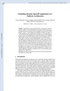
Figure 21: Architecture and use case for asynchronous monitoring in MGSim. simulation model was configured to run the classical Whetstone benchmark7 (a sequential program) using an Apple MacBook Pro as simulation host. The monitor thread was configured to sample the simulation cycle counter and the counter for the number of instructions executed in the cores’ pipeline. The sampling rate was configured to 1000 samples/s. The execution of whet.c lasted for approximately 4.22 real seconds, little over 2.3ms of simulated time; it ran about 3.1M instructions. During this time, the monitor thread produced 3705 samples at an approximated effective rate of 876 samples/s. The readtrace utility was subsequently used in conjunction with GNUplot to produce the figure. As the figure shows, for this model and this host MGSim runs approximately 200K instructions per real second (KIPS) in general, or 150-200x slower than an equivalent hardware implementation. This perspective gives a better view of the simulation speed than the naive estimation based on the final counts, which indicate 3.1 × 10⁶ /4.22 or about 740KIPS for this particular program.
5.3
Performance counters
Next to the monitoring facilities provided above, which are fully “external” and invisible to the simulated platform, MGSim’s library also provides an interface to enable performance introspection by simulated programs. As a first step, MGSim’s standard core model support the standard ISA features to expose performance counters where they exist. For example, its Alpha-based D-RISC model supports Alpha’s rpcc instruction to read the core’s cycle counter. Moreover, MGSim’s library provides a component called PerfCounters. This can be used by any core model at its memory interface to redirect loads to a specific range of addresses to performance counters. When this is configured, a program can introspect the progress of the simulation by reading from fixed memory ranges. At the time of this writing PerfCounters provides access to counters for the number of clock cycles, executed instructions and issued 7 http://www.netlib.org/benchmark/whetstone.c
29
Simulation performance of MGSim simulating a 1GHz model on an Intel Core2 Duo 2.4GHz simulation host running the whet.c benchmark on the simulated platform 5.5e+08
sim. instructions per sim. seconds (performance of whet.c) sim. instructions per real second (performance of MGSim) sim. cycles per real second (performance of MGSim)
700000
5e+08 4.5e+08
600000
4e+08 3.5e+08
500000
3e+08 400000 2.5e+08 300000
2e+08 1.5e+08
200000
1e+08 100000 0
simulated instructions per simulated second
simulated cycles or instructions per real second
800000
5e+07 0
0.0005
0.001 0.0015 simulated seconds
0.002
0 0.0025
Figure 22: Example application of asynchronous monitoring. memory requests, between others. This mechanism was implemented to enable precise reporting of MGSim statistics from the start to end points of a computation expressed in source code (e.g. C). It is not intended as a realistic model of performance counter interfaces found in real hardware.
6
Shortcomings and possible future work
We have presented so far the state of MGSim’s framework and its standard component library at the start of 2013. Our experience using MGSim for architecture research and education has revealed two serious shortcomings. The first is the common occurrence of implementation or design errors when implementing a new model in MGSim. The most common error is the definition of deadlocking circuits due to circular dependencies. Although the component model exposes all dependencies between buffers and processes, the MGSim framework is not yet able to analyze and detect circular dependencies automatically. The implementation of such a detection mechanism would significantly reduce the time required to troubleshoot modeling errors. The second shortcoming is the lack of a facility to checkpoint/restore the entire simulation state. When a failure occurs, the only mechanism available to-date to reproduce the issue is to re-play the entire execution scenario since the start of the simulation. If the program further uses I/O, an exact re-execution is simply impossible. This becomes an issue particularly when troubleshooting long-running software within the simulated platform. Mechanisms to serialize and de-serialize the simulation state, similarly to the “freeze” feature of vir-
30
tual machines, would greatly increase the suitability of MGSim as a sandbox environment to troubleshoot simulated software. Next to these shortcomings, the question arose of what to do about the similarities between MGSim and Gem5, discussed previously in section 2.3. Despite the different project goals, the overlap between the technical approaches is striking; in particular, the inter-component interfaces, component granularity and configuration facilities are intriguingly similar between the two projects. This raises two opportunities. The first is to investigate whether MGSim’s library of memory models could be reused with Gem5, which is somewhat still lacking in this regard. The other is to determine whether Gem5’s core models could be reused with MGSim, to provide increased platform compatibility to programs running on the simulated platform.
7
Summary and conclusions
We have presented MGSim, an open source framework and component library to simulate many-core processors. MGSim’s framework is written in C++ and implements a highly configurable, discrete-event, multi-clock simulation engine. Its library of components provides a versatile hardware multithreaded in-order RISC core supporting multiple ISAs, multiple memory interconnects, and an I/O subsystem which enables full-system emulations. Its comprehensive inspection and monitoring facilities make it suitable for both architecture research and education. MGSim is currently used at the University of Amsterdam and its partners. Its applications include scientific research on the Microgrid architecture [15] and general graduate-level education on processor, cache and memory architectures. Performance-wise, MGSim is known to run models containing thousands of components at 100-1000KIPS on conventional desktop-grade hardware. MGSim is similar to Gem5 [2], another C++-based framework for discreteevent, component-based multi-core simulations. The two frameworks run with comparable performance. Where Gem5 focuses on compatibility with real hardware and intra-core accuracy on models with few cores, MGSim focuses on implementation simplicity and accuracy with large many-core models.
Acknowledgements MGSim’s framework and main component models were originally designed and implemented by Mike Lankamp. MGSim is currently under stewardship of the authors of this article. The development of MGSim so far was funded by the Dutch government via the project NWO Microgrids, the European Union under grant numbers FP7-215216 (Apple-CORE) and FP7-248828 (ADVANCE), the University of Amsterdam, and grants by the China Scholarship Council. The authors would like to thank Carl Joslin, Michiel W. van Tol, Thomas Bernard and Andrei Matei for their thorough evaluation and testing of the MGSim tool chain during its inception, as well as Zhang Li for his contribution of the CDMA model “ZLCOMA.”
31
References [1] T. Bernard, K. Bousias, L. Guang, C. R. Jesshope, M. Lankamp, M. W. van Tol, and L. Zhang. A general model of concurrency and its implementation as many-core dynamic RISC processors. In W. Najjar and H. Blume, editors, Proc. Intl. Conf. on Embedded Computer Systems: Architecture, Modeling and Simulation (IC-SAMOS 2008), pages 1–9. IEEE, Samos, Greece, July 2008. ISBN 978-1-4244-1985-2. [2] Nathan L. Binkert, Ronald G. Dreslinski, Lisa R. Hsu, Kevin T. Lim, Ali G. Saidi, and Steven K. Reinhardt. The M5 simulator: Modeling networked systems. IEEE Micro, 26:52–60, 2006. ISSN 0272-1732. doi:10.1109/MM. 2006.82. [3] A. Bolychevsky, C.R. Jesshope, and V.B. Muchnick. Dynamic scheduling in RISC architectures. IEE Proceedings - Computers and Digital Techniques, 143(5):309–317, September 1996. ISSN 1350-2387. doi:10.1049/ip-cdt: 19960788. [4] F. Dahlgren and J. Torrellas. Cache-only memory architectures. Computer, 32(6):72–79, June 1999. ISSN 0018-9162. doi:10.1109/2.769448. [5] T. D.Vu, L. Zhang, and C. R. Jesshope. The verification of the on-chip COMA cache coherence protocol. In International Conference on Algebraic Methodology and Software Technology, pages 413–429, 2008. ISBN 978-3540-79979-5. [6] Antonio González, Mateo Valero, Nigel Topham, and Joan M. Parcerisa. Eliminating cache conflict misses through XOR-based placement functions. In Proc. 11th International Conference on Supercomputing (ICS’97), pages 76–83. ACM, New York, NY, USA, 1997. ISBN 0-89791-902-5. doi:10. 1145/263580.263599. [7] E. Hagersten, A. Landin, and S. Haridi. Ddm-a cache-only memory architecture. Computer, 25(9):44–54, September 1992. ISSN 0018-9162. doi:10.1109/2.156381. [8] Michael A. Hicks, Michiel W. van Tol, and Chris R. Jesshope. Towards Scalable I/O on a Many-core Architecture. In International Conference on Embedded Computer Systems: Architectures, MOdeling and Simulation (SAMOS), pages 341–348. IEEE, July 2010. ISBN 978-1-4244-7937-5. doi: 10.1109/ICSAMOS.2010.5642045. [9] Raphael ‘kena’ Poss. On the realizability of hardware microthreading— Revisting the general-purpose processor interface: consequences and challenges. PhD thesis, University of Amsterdam, 2012. Available from: http://www.raphael.poss.name/ on-the-realizability-of-hardware-microthreading/. [10] P. Kongetira, K. Aingaran, and K. Olukotun. Niagara: a 32-way multithreaded SPARC processor. IEEE Micro, 25(2):21–29, March/April 2005. ISSN 0272-1732. doi:10.1109/MM.2005.35.
32
[11] M. Lankamp. Developing a Reference Implementation for a Microgrid of Microthreaded Microprocessors. Master’s thesis, University of Amsterdam, Amsterdam, the Netherlands, August 2007. Available from: http://dist. svp-home.org/doc/mike-lankamp-ref-microgrid.pdf. [12] Mike Lankamp. Design and Evaluation of a Multithreaded Many-Core Architecture. PhD thesis, University of Amsterdam, 201x. To appear. [13] F.H. McMahon. The livermore FORTRAN kernels: A computer test of the numerical performance range. Technical Report UCRL-53745, Lawrence Livermore National Lab., CA (USA), Dec 1986. [14] Raphael Poss, Mike Lankamp, M. Irfan Uddin, Jaroslav Sýkora, and Leoš Kafka. Heterogeneous integration to simplify many-core architecture simulations. In Proc. 2012 Workshop on Rapid Simulation and Performance Evaluation: Methods and Tools, RAPIDO ’12, pages 17–24. ACM, 2012. ISBN 978-1-4503-1114-4. Available from: pub/poss.12.rapido.pdf, doi:10.1145/2162131.2162134. [15] Raphael Poss, Mike Lankamp, Qiang Yang, Jian Fu, Michiel W. van Tol, and Chris Jesshope. Apple-CORE: Microgrids of SVP cores (invited paper). In Smail Niar, editor, Proc. 15th Euromicro Conference on Digital System Design (DSD 2012). IEEE Computer Society, September 2012. ISBN 9780-7695-4798-5. Available from: pub/poss.12.dsd.pdf, doi:10.1109/DSD. 2012.25. [16] Li Zhang and Chris R. Jesshope. On-Chip COMA Cache-Coherence Protocol for Microgrids of Microthreaded Cores. In Bouge and et al., editors, Euro-Par Workshops, volume 4854 of LNCS, pages 38–48. Springer, 2007.
33