Micro Flow Bio-Molecular Computation Ashish Gehani and John Reif Department of Computer Science Duke University ∗ Abstract In this paper we provide a model for micro-flow based bio-molecular computation (MFBMC). It provides an abstraction for the design of algorithms which account for the constraints of the model. Our MF-BMC model uses abstractions of both the recombinant DNA (RDNA) technology as well as of the micro-flow technology and takes into account both of their limitations. For example, when considering the efficiency of the recombinant DNA operation of annealing, we take into account the limitation imposed by the concentration of the reactants. The fabrication technology used to construct MEMS is limited to constructing relatively thin 3D structures. We abstract this by limiting the model to a small constant number of layers (as is done with VLSI models). Besides our contribution of the MF-BMC model, the paper contains two other classes of results. The main result is the volume and time efficient algorithm for message routing in the MF-BMC model, specifically useful for PA-Match [Rei98a]. We will show that routing of strands ·D between chambers will occur in time O( N m·n ), where N is the number of strands in the MFBMC, n is the number of chambers where RDNA operations are occurring, D is the diameter of the topology of the layout of the chambers, and m is proportional to the channel width. N 2 log N n Operations that need annealing, such as PA-Match, are shown feasible in O( ) volume n 2 instead of the previous use of Ω(N ) volume, with reasonable time constraints. Applications of the volume efficient algorithm include the use of the Join operation for databases, logarithmic depth solutions to SAT (Boolean formula satisfiability) problems and parallel algorithms that execute on a PRAM. Existent algorithms can be mapped to ones that work efficiently in the MF-BMC model, whereas previous methods for applications such as PRAM simulation in BMC were not both time and volume efficient. Our other class of results are theoretical lower bounds on the quantities of DNA and the time needed to solve a problem in the MF-BMC model, analogous to lower bounds in VLSI. We bound the product BT from below, and further show that BT 2 has a stronger lower bound of I 2 . Here B is the maximum amount of information encoded in the MF-BMC system at a time, T is the time for an algorithm to complete, and I is the information content of a problem.
1
Introduction
A significant aspect of chemical reactions is the randomness with which they occur at the molecular level even though there is a discernible pattern at a higher level as described in kinetic models [Win98, Wet97, SAS96]. One of the results is that even though we can predict that a reaction between two molecules will eventually occur, the larger the volume in which the reactants exist, the less likely it is and so the longer it will take. This is a situation where we wish particular reactants to interact with each other but not with other incidental complexes as that merely increases the overall time before the desired reaction is completed. In such a situation if we were able to place molecules between which an interaction was desired, into a smaller volume then they would interact much more quickly with high likelihood. ∗
Surface address: Department of Computer Science, Duke University, Durham, NC 27708-0129 Email: {gehani,reif}@cs.duke.edu Supported by Grants NSF CCR-9725021 and CCR-96-33567 and Army Research Office Contract DAAH-04-96-1-0448.
1
Conversely, there are certain reactants that we would prefer to isolate. While the ability to perform operations in parallel on the entire data set has advantages, it brings with it the drawback that reagents added to execute an operation necessarily interact with all the bio-molecular material present, even that which it does not need to. In addition, the presence of extraneous material increases the chance of partial matching and other such incomplete interactions occurring, causing avoidable errors. In such cases, we would like to be able to separate the data set where possible. Living systems have evolved a simple method to effect some control in such situations. We refer here to the division of an organism into its many constituent cells within which independent bio-chemical reactions occur. Through the use of a circulatory system, materials are routed to particular cells which perform different operations in parallel on the material. In addition the material can be processed and then sent along to another destination through the infrastructure of the circulatory system. By having limited volumes in each cell, the reactants that need to interact can do so efficiently. Certain highly reactive chemicals which have positive uses but can have a detrimental effect on other reactants and reactions can be isolated within particular cells, where they can be productively used without affecting other material. a’ a’
a Strands a and a’ interact more quickly in a smaller volume.
a
Analogously, we propose a framework in which BMC can occur in a large number of isolated regions of limited volume. As with a living system, there will be an associated infrastructure that will allow reactants, reagents and associated material to be transported from one region to another. Since our method will make use of micro-flow device technology, we refer to the framework as micro-flow biomolecular computation (MF-BMC). A 3D MEMS fluid system has been proposed in a different context [Iku97] but does not examine the BMC poten-
tial in any detail. All the operations used for DNA computing as described by Adleman [Adl96], Lipton [Lip96] and Reif [Rei98a, Rei97] will be supported in the MF-BMC framework. The details of the operations can be found in their respective papers. One of the early concerns regarding the scalability of BMC was the issue of limiting the number of steps that must be performed in the laboratory [Adl96, Rei98a]. We note that the issue has dual roots. The first is the long periods of time needed for operations such as anneal. As outlined in Section 1, we propose to alleviate this with smaller volumes. The other reason is that it is not practical to expect a human laboratory technician to be able to execute a large number of steps. Three different approaches arose to deal with the latter. One was to attempt to effect molecular self-assembly that would obviate the need for human intervention as described by Erik Winfree [Win95]. Another was the reformulation of BMC models so that the complexity analysis incorporated a notion of the operations with the restriction of utilizing a single laboratory technician [AGD97]. A third possibility was the introduction of automation to perform the necessary tasks, as described in the paper introducing the idea of a stickers machine based on the sticker model [RWB+ 96]. Our model builds further on this approach. We assume the mechanical equivalent of an army of technicians acting in parallel and controlled by a conventional micro-processor, in contrast to the first and second approaches. Algorithms, such as Ogihara’s solution to SAT [OR97], which have significantly higher complexity in the “strong model” than in the “weak model” and are thus deemed impractical [AGD97], can be implemented practically in the MF-BMC since distinct operations can be executed at distinct locations simultaneously. The MF-BMC framework can be differentiated functionally from the stickers machine in two respects.
2
The first is the scale on which the total volume is expected to be divided into smaller volumes. Since the reduction in total volume needed will be seen to be proportional to the scale of this division, this scale will necessarily be large. Secondly, since the topology envisioned is a two dimensional array, there exist, and we describe, methods to efficiently route strands between chambers. All MEMS devices are assumed to be controlled by a micro-processor.
2
Motivation
Overview and Assumptions. The model described will have a fixed number of layers. In each layer there will be a grid along whose lines will run channels for liquid transport. At the grid points will be located chambers in which biochemical reactions can occur. Architectural limits much like those of VLSI models give rise to some of the model’s assumptions. We can summarize these as follows. The first limit is the small constant number of planar layers due to the current limits of MEMS fabrication technology. The next is the lower bound on the size of any component of the system. If the volume of a chamber is too small then meaningful computation can not be effected in it. If area of cross-section of a channel is too small then practical movement of fluid volumes will not be possible. Also, the rate of transport of fluids between chambers must be sufficient for routing between chambers to be practical. Further constraints analogous to the Meade-Conway design rules of VLSI may be added to carry the model from a theoretical proposition to one useful in practice. Additionally, we assume that we can detect hybridizations that are exact, and we assume that these occur without error. Further we do not consider kinetics asymptotically as we expect to run them for only constant periods of time with the focus on interaction between local pairs of strands. Strand Routing Efficiency. The process by which a strand in a chamber reaches another strand with which it will combine using some RDNA operation such as anneal or ligate, is essentially probabilistic. Heuristics exist that allow the manipulation of quantities such as the melting temperature and the rates of reactions by altering the salt concentration, metal ion concentration, the temperature of the solution, the hydrogen potential, and the ratio of purine bases to pyrimidine bases [HG97, RDG+ 97, Wet97, SAS96]. For significant yields of a particular product, the reactant concentrations must necessarily be adjusted appropriately [KMRS96, Win98]. This is where the need for quadratic volume for guaranteed reactions between strands enters, as explained below. For the purpose of analysis in this section, we assume that strand concentration remains relatively invariant. That is, a reference to O(N ) volume has implicit in it that there are O(N ) times as many strands as in a unit volume. Additionally, since the model being developed is for effecting computation, rather than effecting biochemical reactions till they reach their thermodynamic equilibrium, the creation of even single copies of expected products in reactions is the desired result in a chamber. Specifically, if mi copies of strand si interact with mj copies of strand sj resulting in mh copies of the heteroduplex sh , then mh > 0 is considered a successful routing between the two strand types si and sj . In N volume, the initial rate of production of sh will be dcdth = kf .ci .cj , where ch is the concentration of sh , kf is the constant associated with the forward reaction, ci is the concentration m mi , and cj is the concentration of sj , which is kNjA . NA is the Avogadro constant of si , which is kN A and k is a fixed scaling factor such that the total number of strands in N volume is kNA . We expect a single copy of sh in the N volume would be produced immediately with probability proportional to the rate dcdth . Therefore in a volume dc1h , we would expect a single copy of sh to be be formed dt
immediately with constant probability independent of N . Simplifying this by considering the case 3
where mi = mj = 1, then
1
dch dt
=
N2 kf .
Thus by using a total O(N 2 ) volume, that is one with O(N )
copies of si and O(N ) copies of sj among a total of O(N 2 ) strands, one can expect the immediate production of a copy of sk with fixed probability. This result is borne out by considering the strand interaction from a different point of view as well. Suppose we assume that the strands are moving with Brownian motion in the chamber. In a chamber with N copies of strands si , denoted by si1 , . . . , siN and N copies of sj , denoted by sj1 , . . . , sjN , among a total of N 2 strands, the probability that si1 interacts immediately with sj1 is N12 . The probability that si1 interacts immediately with any sjx , where x ∈ {1, . . . , N } is N. N12 = N1 . The probability that si1 does not interact with any sjx is 1 − N1 . Thus the probability that all siw , where w ∈ {1, . . . , N }, do not interact with any sjx is (1 − N1 )N , which is 1e , where e is the natural logarithm base, a constant. Thus the probability that one of the strands of type si interacts immediately with one of the strands of type sj is 1 − 1e , a constant. Further, by using r.N log N volume, where there are r. log N copies of each of the N different 1 1 types of strands, the probability of hybridization not occurring is (1 − N1 )rN. log N = er. log N = Nr . The probability of each of the different N strands being routed to one of the copies that we desire it to interact with is therefore 1 − N −r , which is close to unity for reasonable r. After T time steps, we would expect that the computation would achieve the desired result with probability (1 − N1r )T . In particular, by increasing the volume redundancy r linearly, we can increase the number of time steps T exponentially without decreasing the probability of a successful computation.
Organization Of The Paper Section 3 describes the abstraction of the MEMS technology used in our description of the MFBMC. In Section 4 we present the design of the model including the chambers, channels, control, input and output. Section 5 examines how each of the RDNA operations can be implemented using MEMS and considering the constraints created by the scale on which the RDNA operations are being performed. Section 6 describes routing within a chamber. In Section 2 we discuss how the routing of strands from one chamber to another can be implemented. Section 7 then described how a PRAM can be simulated in the MF-BMC and discusses other applications. Finally, in Section 8 we give some theoretical lower bounds on the memory, the information at the interface, and information flow within the MF-BMC. These also connect the quantity of DNA used in the system and the time needed to perform a computation, to the information content of the problem being solved.
3
MEMS Micro-Flow Devices
In order to replace the laboratory technician, we must create a system to effect the same actions that the technician would perform. This is achieved by the use of MEMS pumps, valves, and sensors. We only refer to the devices as abstractions even though there is a wealth of available MEMS technology. The reason is that the choice is an engineering issue that depends on many constraints. In general, the scale of the MF-BMC and the budget available for building the MF-BMC will affect the choice of the implementation. In addition, other factors specific to the device will play a role. For example, consider the use of a micro-pump. In the event that a larger budget is available, several pumps of different technology could be used. One would be suited to maximize flow when the strands are expected to be linear. Another would minimize turbulence when the data strands
4
are expected to be more complicated structures. A third would be used when the strands are being pumped vertically. Actuators. These are the devices that translate a control signal into some form of mechanical motion. There are numerous available implementations [SE92, VvdSJ+ 92, MEB+ 92, ALL95]. In the description of the model, we will use the notation A(i) to refer to the operation of an actuator in the component i, where i can be either a chamber or a channel as described in Section 4. An actuator can either be on or off and this is denoted by 1 or 0 respectively when specifying this in an algorithm running on the controlling micro-processor. Micro-valves. One of the critical components of a system that controls the flow of DNA strands and complexes is necessarily a valve or regulator of some sort. Details of the constructions can be found in the literature [VvdSJ+ 92, MEB+ 92, ALL95]. In the description of the MF-BMC model, we will use the notation V(i) to refer to the operation of a micro-valve in the channel i as described in Section 4. A micro-valve can either be open or closed and this is denoted by 1 or 0 respectively when specifying this in an algorithm running on the controlling micro-processor. Depending on what type of actuator is used, the micro-valve will have different characteristics such as how quickly it can open and close, whether it is better suited to situations where it is open most of the time or to situations where it is closed most of the time, whether it can control flow across a channel with a large area of cross-section, and what pressure it can withstand. In many situations, it will be appropriate to place several micro-valves based on different technologies at a given point where flow control is required, along with micro-sensors that will activate the micro-valve most suited to the immediate need, and deactivate the remaining ones. Three-way flow control has been implemented [SE92] and provides the abstract basis for performing selection between multiple routing paths. It is easily generalized to allowing regulators at a node to connect a chosen source channel to a chosen destination channel. Micro-pumps. In order to transport the information around the MF-BMC, micro-pumps are employed to move the solution and the DNA strands contained in it, that are in a particular chamber to another chamber, as described in Section 4. Refer to the literature [SE92] for details. For the purpose of the model, the abstracted representation P(i) will be used. It refers to the appropriately chosen micro-pump operating along the channel i as described in Section 4. A micropump can either be operating in one of two directions or it can be off and this is denoted by setting it to 1, −1 or 0 respectively when specifying its use in an algorithm to the controlling micro-processor. The 1 refers to pumping in the direction of the chamber with the larger subscript, and −1 refers to the pumping from the chamber with the larger subscript. (Note that the reference i to a channel implicitly includes two chambers as parameters. It is the subscript of these that we refer to here.) As with micro-valves, depending on the underlying technology used for the actuator, the micro-pumps have various characteristics such as the rate at which volumes can be pumped, the pressure that can be built up by the micro-pump without side-effects, and the ability to reduce or contain aspects such as rippling or turbulence, which are especially important in the context of DNA computing. Flow sensors. In the later description of the model, the notation Sen(i) will refer to a sensor that is located in the channel i or the chamber i. A flow-sensor reports 1 to the controlling microprocessor if the flow is above a certain threshold, and 0 otherwise. The implementation of the
5
abstraction will be based on a liquid flow sensor, the type most suited to our needs, which can be of several varieties. Refer to [SE92, VvdSJ+ 92, MEB+ 92] for more details. Flow control systems. By coupling a flow sensor’s output to a micro-valve’s actuator, and to a micro-pump’s actuator if necessary, a feedback system is created whereby micro-flow in a system can be largely automatically controlled. Digital to Analog Conversion. For the purpose of the micro-processor effecting control upon various MEMS components, we note that this is easily implemented by the use of micro-flow devices that use electrical circuits in them, such as the solenoid of an electro-magnet or the resistor of a heater. This is because the micro-processor need only use an amplifier to increase or decrease the voltage and current as necessary, and then let the output be connected through wires to the relevant micro-flow devices.
4
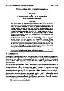
Architecture Channel connecting different layers
Channel
Chamber
Lowest layer in view Proposed architecture for Micro-Flow Bio-Molecular Computation consists of several planar layers, in which an array of chambers connected by channels exists. Channels from layers above bring in data strands, reagents needed for reactions.
The architecture of the model envisioned consists of a small constant number, Pmax , of planar layers. We denote these planes by P(i), where i ranges from 1 to Pmax . The composition of each one is described below. We note here that the planar nature is due to the inherent constraints of current MEMS fabrication. In addition, although we limit our model to a fixed number of layers, in principle if the micro-flow device technology were to allow arbitrary vertical scaling, then our model and the associated analysis could be scaled to 3D. The intuition for this can be seen in
the literature on parallel architecture design [Lei92]. The architecture relies on three orthogonal technologies, namely DNA computation in a testtube as previously envisioned [Rei98b], packet routing in networks, and micro-flow devices. In addition, the various aspects are tied together using a conventional silicon based micro-processor. As we proceed to describe the model, we refer to particular implementations of the technologies mentioned. We note, however, that in all three fields there are numerous competing alternatives that could be used in place of the specific instances that we have chosen to use.
4.1
Composition Of A Layer
A typical layer is solid all through with four exceptions. These are (i) the chambers in which RDNA operations occur, (ii) the channels which connect the chambers, (iii) the control lines which allow a single silicon-based micro-processor to synchronize the RDNA and MEMS operations, and finally (iv) the MEMS devices that effect the routing.
6
4.1.1
Chambers
Layout. Chambers are cavities in which the RDNA model computations can occur. We denote these regions by R(i), where i ranges from 1 to Rmax , the number of chambers in the MF-BMC. Some planes will use a regular layout in the form of a grid of chambers. Typically, this would be the case for plane P(1), where the chambers in which the RDNA operations are executed. Other planes, where reservoirs that hold pools of strands at intermediate points during their transfer from one chamber to another, would also have such structure. Such planes have h chambers in each row and w chambers in each column, giving us a value of h × w for Rmax . When such a layout is implicit, we refer to the chamber R(i · w + j) with the notation R(i, j), where 1 ≤ i ≤ h, and 1 ≤ j ≤ w. When there is ambiguity regarding which plane a chamber is in, we use the notation (P(i), R(j)) to disambiguate the reference. Structure. A chamber R(i)’s height, width and depth respectively are denoted by hc (R(i)), wc (R(i)), and dc (R(i)). The maximum volume that can be stored in the chamber is therefore hc (R(i)) × wc (R(i)) × dc (R(i)). The aspect ratio is the quotient of the height and the width. If it is not within a certain factor from unity, then the chamber’s design could introduce effects such as uneven diffusion of reactants. Reagent/Routing
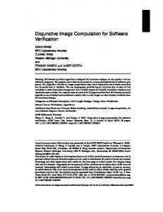
Micro-flow Enablers. Each chamber R(i) has an inlet and outlet on opposing sides. The inlet flow Reagent Reagent Micro-Valve Micro-Pump is controlled by a micro-valve Vinlet (R(i)), and the 000 111 000 111 000 111 outlet flow by a micro-valve Voutlet (R(i)), both of Outlet Micro-Thermometer Micro-Emitter Micro-Anode 00 11 00 11 which are of the type described in Section 3. These 00 11 11 00 w l 00 11 00 11 00 11 00 00 11 11 are for DNA strands to be brought in and removed. 00 11 00 11 0 1 00 11 Outlet 0 1 Micro-Cathode 0 1 We note here that each inlet and outlet have the 00 11 Micro-Valve 0 1 00 11 0 1 00 11 Micro-Sensor h 00 11 ends of channels from up to four other chambers 00 11 00 11 Micro-Heater Chamber Inlet Inlet ending at them if the architecture is a regular grid Immobilizer Strands Micro-Valve Reservoir Micro-Valve of chambers in the plane. From an opening in Micro-Solenoid Reservoir the ceiling of the chamber, controlled by a microReservoir Micro-Pump valve Vreagent (R(i)), reagents may be introduced. Through the use of this micro-valve’s interface to the layer above and the additional power provided by a micro-pump denoted by Preagent (R(i)), reagents may be flushed out. In addition, this is the interface that will be used to connect to layers above and below. Below each chamber, a reservoir of dimensions equal to that of the chamber, is present for temporary storage. It is denoted R′ (i), and is connected to the chamber via a micro-valve, denoted Vreservoir (R(i)). Contents can be pumped to and from it through this valve by the activation of a two-way micro-pump, denoted by Preservoir (R(i)). RDNA Enablers. Near the inlet and outlet will be located two electrodes, through which current is passed when gel electrophoresis is performed in the chamber. The cathode, denoted E − (R(i)), is placed near the inlet, and the anode, denoted E + (R(i)), is placed near the outlet. This is due to the fact that DNA is negatively charged on account of its sugar-phosphate backbone which contains P O4− anions. Using solenoids, denoted Sol(R(i)), which are embedded above and below the chamber, magnetic fields may be introduced as required. By placing a suitably protected resistor based micro-heater, denoted H(R(i)), in the bottom of the chamber, heating of the contents 7
may be performed, with convection helping circulate the materials. By placing an optical emitter and sensor, denoted OE(R(i)) and OS(R(i)) respectively, at the two ends of the tube, required measurements may be taken. The cathode, anode, solenoids, heater and emitter can all be either on or off, and when specifying this to the controlling micro-processor this is done by setting the respective abstraction to 1 or 0 respectively. The optical sensor, as in the case of the flow sensor of Section 3, will provide feedback to the micro-processor according to whether its reading crosses a threshold. Each chamber is equipped with a micro-thermometer, denoted T (R(i)) which can be read by the micro-processor in real-time and provides continuous valued feedback. A final type of RDNA enabler present in each chamber is a set of known nucleotide sequences that have been anchored to the walls of the chamber. Various operations can take advantage of these as they are always known ahead of time and are distinctly encoded for each chamber. For example, consider the problem of immobilizing all strands of a certain class that are in the chamber R(i). Assume that the strands anchored in the chamber are composed of the single stranded sequence sR(i) called the anchor strands, and the single stranded DNA to be immobilized are of sequence types t1 . . . tm , where m is the count of the number of different strands to be immobilized. We assume without loss of generality that sR(i) and all the tj , where 1 ≤ j ≤ m, are oriented in the same direction. The complementary immobilizer strands s′R(i) t′j for all j, where 1 ≤ j ≤ m, can now be introduced. Annealing can be induced and the strands tj will now be anchored down as they will anneal to the immobilizer strands which are annealed to the anchor strands. By choosing sequences for sR(i) which bind more strongly to their complement that the various tj do, denaturing can be selectively performed such that only the tj strands break away. 4.1.2
Channels
The second type of exception to the solidness of a layer consists of the channels, which are conduits connecting the various chambers as required. A channel is fully specified by its two endpoints, each of which must be a chamber. Thus a channel connecting two topographically adjacent chambers R(i) and R(i + 1), would be denoted by C(R(i), R(i + 1)). In addition, each channel has a micro-pump as described in Section 3 placed in it so as to facilitate the flow of the contents from one chamber to another. The micro-pump for the above example channel would be denoted by P(C(R(i), R(i + 1))). Similarly the channel’s length and radius of cross-section would be denoted by lc (C(R(i), R(i + 1))) and rc (C(R(i), R(i + 1))), respectively. The area of cross-section of the channel is referred to as its width, m(C(R(i), R(i + 1))). The micro-pump’s capacity would be such that the unit of volume it could pump in a unit of time would be proportional to the area of cross-section, m = πrc2 , of the channel in which it is pumping. To complete a full operation of the RDNA model would require moving the contents of a chamber to another one. The time taken for this would thus be inversely proportional to the channel width, proportional to the volume of the chamber and would have a latency introduced to get the channel filled and emptied. We could thus formulate the time to transfer the contents from c ×dc + c′ lc . As in VLSI models, the factor c′ is initially treated one chamber to another as τ = hc ×w c×m as 0 since the term is miniscule relative to the other one. Note that a channel can connect two reagent interfaces of two chambers vertically over each other, and this is what allows transmission between layers. As in the case of VLSI design, channels transporting the raw material of the computation’s encoding and reagents, the analogue of power lines in a VLSI chip, may eventually be the most significant constituent as judged by area or volume as a metric.
8
4.1.3
Control Lines
Since all the MEMS devices are controlled by a single micro-processor, there must be lines of control from each of them. These pass through conduits bored into the solid. Laying these out should not pose a significant problem in early implementations as there are three degrees of freedom for a path from each device. It may become a constraining factor as in the case of VLSI when significant miniaturization of the chambers occurs.
4.2
Specialized Layers
We will now describe certain layers that have a specialized design. Material Input And Output. One type of layer specially adapted would be the material layer. It would consist of the large reservoirs containing the various fluids needed for the operation of the MF-BMC. These would be located at the surface so that they may be easily replenished. Reservoirs containing various constituents such as the building blocks for the data in solution form, the reagents for the RDNA operations, the liquid used to flush a chamber or channel to clean it out after it has been used, and the other agents such as gel for electrophoresis, are all stored in this layer. By placing them in the topmost layer, the implicitly higher potential energy that they will have, can be exploited for micro-pumping and flushing purposes. There will be a finite number of reservoirs accessible from this layer. Controlling each one’s content’s flow will be a micro-pump and a micro-valve, with the expected notation. For example the flushing liquid’s reservoir would be controlled by the micro-valve Vf lush (P(Pmax ), R(i)), and the micro-pump Pf lush (P(Pmax ), R(i)), on the assumption that the reservoir is in the topmost plane and in chamber i in this plane. Routing Layer. While the layer described above is completely general and allows for routing of strands between any two chambers, we propose special form routing layers which can be used for optimizing routing. We will not exploit the properties of such layers in the remainder of the paper, but their utility in a practical MF-BMC machine is still valid. Such layers would be solid with three types of exceptions. The first consists of channels laid out for the purpose of routing reagents, reactants and other chemicals needed in the general RDNA layers. The layout would be a grid with multi-way microvalves at the crossing points of the various conduits. Such a system would allow very efficient transfer of material along a path since it does not have to pass through the ordinary chamber at inter-connection points. It would have the disadvantage of not allowing the concurrent transport of materials along two paths that cross at any inter-connect since the absence of chambers means the contents can not be intelligently sorted out. The second exception is the association with each inter-connect point of a fixed number of buffers, each of which is a cavity, that are connected to the crossing point via a multi-way microvalve that allows flow to be redirected into a buffer for temporary storage. These would act as analogues of scratch registers in a silicon based computer, as they would provide fast intermediate storage. The final provision would be for vertical columns that would allow the passage of control lines from the MEMS devices as present in the general form layers.
4.3
Using the MF-BMC
The two aspects of the MF-BMC that must be controlled by the programmer are the data input and output and the sequence of operations to be performed upon it. In the sections below we 9
describe how this is to be done. 4.3.1
Data Input
The user of the MF-BMC will be able to provide it with data in three different methods. These will be summarized below. 2D Strand Arrays. The first method is the use of DNA-on-a-chip technology [Suy98] if copies of particular strand encodings are required as input. The single stranded template for these strands can be replicated using a DNA-chip as follows. The template strands are biotinlylated. The chip will have a solid support base populated with fixed DNA sequences. DNA strands which will serve as the templates for the data being constructed and with prefixes that are Watson-Crick complementary to the fixed solid support sequences will be introduced. The complementary regions are allowed to anneal. Now there exist a population of templates held down to the chip. Many small sub-sequences of all possible combinations are introduced and appropriate primers are introduced. Annealing that makes the single stranded templates double stranded is allowed to occur. After flushing extra sub-sequences out, ligase is introduced. Next, by denaturing and then washing over magnetic beads with avidin, the template strands can be immobilized. The desired data is then routed for use and the templates can be recovered from the beads. By introducing suitable template strands from a library of stored strands, data strands can be created. Additional techniques using specific enzymes to extract only desired strands from those grown as well as the use of only certain primers allows finer grain control over the production of data strands. Synthesizers. The above technique’s limitation is that strand length must be limited and complex structures can not easily be created. The next level is the incorporation of a unit that is able to build an arbitrary strand from an abstract specification. Synthesizers of this sort are widely commercially available. They work by chemically adding single nucleotides to the strand being synthesized. External Fabrication. The above methods can not deal with arbitrary structure creation when complexes such as the 2D tiles made of DNA are needed. This leads to the last option which is the possibility for external DNA data manufacturing, followed by its incorporation into the MF-BMC by its introduction at any one of the unused reservoirs in the material layer described in Section 4.2. 4.3.2
Data Output
We will assume that at the end of the computation the results will be encoded in what we term output strands, and that these will be routed to a data output chamber that could be one of the reservoirs in the material layer, or any other location designated and equipped as described below. In general, bioanalytical sensors are implemented as the coupling of chemical transduction, the process of selectively responding to particular compounds, to energy transduction, the resulting of a defined detectable pattern. The chemical transduction processes fall into one of four categories, depending on whether they are based on adsorption, entrapment, cross-linking, or covalent bonding [Cun98]. 2D DNA Chips. As with data input, the first method of reading data output is based on the use of DNA-on-a-chip technology. There are several different implementations available from Affymetrix, HySeq and other companies, as well as work done by research groups at universities 10
such as the one at the University of Wisconsin. A standard technique is to have all data strands tagged with phosphorescent material. A 2D grid of different sequence strands are attached to known locations. The output data strands are washed over and when a complementary strand binds, the optical readout at the point where the strand attaches is read and processed by the micro-processor. Since it knows the mapping from sequences to locations on the chip it can deduce the complementary strand’s sequence. While there is a vast literature available on the field, what is of particular interest are the techniques that can handle high throughput, as described in various studies [CYH+ 96, BKH96, FRP+ 91, PSS+ 94]. External Analysis. Some strands washing through may not have their complements encoded in the library of the DNA strands available, or the strand may be far beyond the length encoded in the library. For such strands, we can have a sequencing unit connected to an output chamber, which is capable of analyzing, nucleotide by nucleotide, the content of a sequence. Since the output may be non-linear in some cases, such as tiles of DNA, and novel methods may be needed for readout, there will be a fallback option routing to a reservoir where external access is easy and the contents may be extracted and further analyzed with other machines.
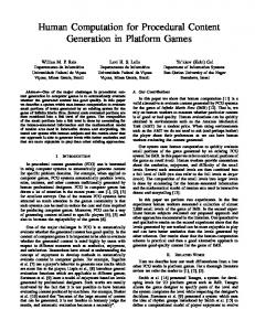
Micro-Processor
11 00 00 11 00 11 00 11
Chamber
h chambers Control Line Channel
Micro-Valve
w chambers In this example, we see a micro-valve that allows control over which of the four adjacent chambers’ outlets are connected to a chamber’s inlet. The micro-processor controls the micro-valve through a control line. (We use the convention that the outlets are located on the right and the inlets are on the left of the chambers.)
4.3.3
Control
A micro-processor is located at a convenient location in the MF-BMC, with all the various control lines from the embedded MEMS in the various layers are connected to it. The micro-processor can control the opening and closing of the valves and the activation and deactivation of the actuators and pumps used for routing the pools of strands from one chamber to another. It can adjust the temperature of a chamber through a heater, the magnetic field through solenoids, and the electric field through electrodes. It can read the temperature of a chamber, the presence of flow in a channel, and the optical density of the DNA in a chamber. It can cause data strands to be generated, and it can read the sequence of an output strand. It can perform any of 11
the other tasks previously described. It is therefore at the micro-processor that a programmer of the MF-BMC needs to implement an algorithm. The various primitives and the notation needed for the BMC and the micro-flow operations have all been provided as the MF-BMC was described. What remains to be stated is that the micro-processor has the capability to perform conditional branching depending on the readings it can make as has been described thus far. 4.3.4
Pipelining
A great strength of our model is that parallel transport between various volumes in which RDNA operations are occurring is feasible practically. An immediate result is that it is possible as well as desirable to carry out pipelining of the computation. The idea was first described in the context of the stickers machine [RWB+ 96]. For example during the implementation of the graph three coloring problem [Adl96], Adleman uses several separate operations on the results of previous separate operations, removing strand encodings of graphs that do not have the three coloring property. We can split all the strands encoding the graphs and their coloring, introducing only a small fraction into a chamber, making the rate at which the operations can be performed in the chamber much higher due to the limited volume. As soon as the result of one separate is available from one chamber, it can be passed to the next chamber where it can undergo the next separate operation, while in the previous chamber the next batch of encodings is undergoing the same operation. This method allows the data set to be split and operated on with lower volumes and thus better DNA computation efficiency, yet no asymptotic increase in complexity of the algorithm. The only loss is the latency involved in filling and emptying the pipeline. Finally, we note that, even though our model suggests that valves and pumps have a binary nature and can be only open or closed, and active or inactive, it is easy to modify it to allow for intermediate states whereby peristaltic transport of the strands along a chain of chambers can occur. This can be seen to have immediate application in the problem of having a large data set encoded with the destination chamber’s address as a prefix on each strand. In this case, by the use of complementary strands affixed by magnetic beads or their equivalent in each chamber with the chamber’s address on them, the data set can be systolically routed through all the chambers and the data for each chamber will be extracted from the solution as it flows by since it will anneal to the address encoding laid out for it.
5
Recombinant DNA Operations Within A Chamber
The goal of the RDNA model was to provide computer scientists with an abstract interface to some of the possible operations available in a laboratory setting. The power and limitation of such models has been explored [WYS96] in connection with the various proposed operations. The operations that have been chosen are those that can be easily effected empirically based on established techniques and tools of the molecular biologist. We adapt them here for use in the context of chambers instead of test-tubes. The details of some of operations, such as the specific primers needed in a PCR, are dependent on the specific encoding of the data, and are therefore to be specified by the algorithm designer. A set of operations was proposed by Adleman [Adl96] and Lipton [Lip96]. These were extended by Reif [Rei98a] based on feasible operations available at the work bench in a molecular biologist’s laboratory. We describe them along with possible implementations in our MF-BMC framework below. Instead of the operations acting upon test-tubes, the ones used in an algorithm effected on a MF-BMC computer operate on chambers. Instead of output being in designated test-tubes, they are in designated chambers. 12
Since all the operations that will be used below and the domains upon which they operate have been stated explicitly in Section 4, we shall refer to them by the generic terms rather than the formalisms introduced.
5.1
Execution of Adleman Model Operations With MF-BMC
Merge operations represent mixing the contents of two test-tubes in the laboratory into one tube in the Adleman model. Temperature and solution concentration is assumed to be such that the contents do not interact chemically. This is easily adapted to mixing the contents of two chambers by routing the pool in the first chamber to the second chamber, where after emptying in it is caused to mix by the slight application of movement effected by a micro-actuator of the form described in Section 3. The operation’s semantics are extended to allow merging into an empty chamber and to an output interface for various purposes such as external storage. Copy operations in the Adleman model represent the replication of the contents of a test-tube, as would be performed using a Polymerase Chain Reaction (PCR) in the laboratory [Cam93]. The assumption is made that the protocol does not introduce significant mutation errors in the contents during replication, and that the relative concentrations remain the same - that is that the PCR replicates all strands equitably. We adapt this as follows. From the reservoirs in the material layer, the salt buffer, the DNTPs (deoxy-nucleotide-tri-phosphates) that are the free nucleotide building blocks, the two primers, the ligase, and the polymerase are micro-pumped into the chamber where the copy operation is occurring. Using a micro-heater created with a calibrated resistor and a micro-sensor together setup in a feedback loop as described in Sections 3 , the temperature of the chamber is regulated to a desired level. The sensor’s sensitivity is set by the micro-processor in the control layer. By cycling repeatedly through temperatures, around ninety-five degrees Centigrade to denature the strands, around fifty-five degrees Centigrade for the primers to bind, and around around seventy-five degrees Centigrade for the polymerase to build along the template strands, the PCR can be effected in the chamber. Detect operations in the Adleman model represent checking whether there are any DNA complexes present in a given test-tube. In the lab, a PCR would be run to amplify trace quantities of any interesting poly-nucleotide sequences that may potentially be present [Adl96]. In the chamber, a PCR is performed as described above. After that, a micro-emitter on one side of the chamber coupled with a micro-sensor on the other side, and controlled by the micro-processor, is used to obtain an OD (optical density) reading that reveals whether any significant quantity of DNA strands are present in the chamber. Separate operations in the Adleman model correspond to using an appropriate reagent in the laboratory to detect the presence of a sequence of nucleotides in the strands in a test-tube, and then separate the resulting two classes of strands into two separate test-tubes, those containing the sub-sequence and those devoid of it. This operation is effected by the introduction of micro-scale magnetic beads which have the complementary encoding embedded on their surface. Strands in solution that contain the target subsequence will adhere to the beads. By the creation of the appropriate magnetic field in the chamber the beads can be made to sink while the remaining solution can be pumped out. By increasing the temperature as needed and deactivating the magnetic field, the target strands can be denatured from the beads. By application of the magnetic field the beads can be immobilized again, and the target strands can be routed to the next chamber. The magnetic beads can be removed by deactivating the field and then washing them out in solution. 13
5.2
Extended Model Operations
We now discuss the RDNA model, which includes all the above operations of the Adleman model, as well as the operations discussed below: Select operations in the RDNA model correspond to finding all strands that contain more than a certain number of base pairs. This is done in the lab by using gel electrophoresis to separate them by weight, since heavier sequences move less in a fixed time period and electric field than do lighter ones. If the length of the chamber permits the separation of the DNA complexes, then a procedure that is the analogue of the above can be executed. We emphasize that there exist significant technical hurdles to effect this. By introducing enough heated liquid agarose electrophoresis gel into the chamber to completely disconnect the buffer near the inlet of the chamber from the buffer near the outlet of the chamber, and allowing the gel to cool to the required temperature, a regular gel electrophoresis setup is effected. We note here that a chamber in which such an operation needs to be performed will have certain lower bounds on its length. This is due to the fact that the migration of the DNA complexes is inversely proportional to the logarithm of its molecular weight. By pumping, with a micro-pump as described in Section 3, the DNA strands to be operated upon into the buffer solution near the inlet of the chamber, then proceeding to activate the current through the electrodes near the inlet and the outlet so as to cause the strands to migrate through the matrix of the gel at a rate inversely proportional to their size, and stopping the current at a time that corresponds to the cut-off in size that is required, the set of DNA strands in the buffer solution near the outlet of the chamber correspond to all those below the specified threshold. These may be micro-pumped to their required destination. The routing can be done as described in Section 6. The current is then reactivated for a period of time sufficient to allow the remaining strands to travel through the matrix. These are also collected in the buffer at the outlet. They may then be micro-pumped to their selected destination. Finally, the electrophoresis gel is removed by raising the temperature in the chamber with a micro-heater to a point where the gel is fluid enough and then pumping it out. If the chamber length is restricted, then alternative techniques such as ultra-filtration [BRB68] can be used. Here the difference in molecular weight of the DNA, coupled with the viscosity of the solution, would result in differential rate of flow of the complexes when transported using a micropump. The smaller complexes would be moved more swiftly. This procedure would have lower reliability and accuracy, but could be executed within constrained dimensions. The membranes used as filters would be capable of differentiating between complexes which are different by an order of magnitude. Alternatively, other recent developments in the form of capillary electrophoresis, micro-dialysis, and miniaturized ultra-filtration can be used [RJ91, SH96, Bak96]. Cleave operations in the RDNA model correspond to using an enzyme that recognizes a nucleotide sub-sequence and makes a nick in a known way [Rei98a]. We work with a simplified model instead of the more complex space of possibilities that can occur in a laboratory setting by limiting the types of enzymes used. This operation is effected in the chamber easily by merely pumping in the required enzyme. Denature in the RDNA model refers to the process of causing double stranded nucleotide sequences to separate into their respective single strands. This has been extensively studied in the laboratory [HG97, RDG+ 97, Wet97]. The change in the Gibbs Free Energy is the change in the enthalpy of the system less the change in the Standard Free Energy of the system scaled by the absolute temperature. Thus, by regulating the conditions such as the temperature and concentration 14
of the reactants in solution, the rate at which the process of denaturing occurs can be controlled. By the application of heat with resistor based micro-heaters and micro-sensors to regulate the temperature, denaturing is effected. Anneal in the RDNA model refers to the process of single strands which have complementary base pairs combining by the formation of hydrogen bonds between the respective complementary base pairs. It has been modeled in the literature [HG97, Wet97, SAS96] with the energetics explained above in the denature operation. It is effected by the control of various conditions such as temperature, concentrations, and reagents. By introducing the required buffers and reagents, and by altering the temperature, annealing can be effected in a chamber. The control of the parameters is necessary since potentially there are many competing strands which may anneal but we wish only the ones designed to match exactly to do so [Win98]. Ligation in the RDNA model is the closing up along the back-bone of open bonds between consecutive bases in a strand. It is effected by pumping ligase into chamber where the operation is occurring.
6
Strand Routing
“Routing” between strands is said to occur when the two strands that need to interact biochemically have done so. Routing in a chamber becomes a concern when operations that need strings to interact are used, such as anneal or ligate in the RDNA model. Reif added the Parallel Associative Match (PA-Match) operation to Adleman’s original model. The Parallel Associative Match (PA-Match) operates on sets of strings encoded in DNA [Rei98a]. Assume that a string from the first set using the sets’ encoding is represented as E(α)E(β). Assume another string from the second set using the sets’ encoding is represented as E ′ (β ′ )E ′ (γ). Then the PA-Match operation transforms all such pairs where β and β ′ are Watson-Crick complementary sub-sequences. The result of any such pair undergoing the operation would be a new sequence of the form E ′′ (α)E ′′ (γ). If in a set of N strands there was only one copy of each of two strands, then obtaining the desired result with fixed probability would require O(N 2 log N ) total volume (with O(N log N ) copies of each of the strands) and O(1) time. (This is explained in Section 2.) We will see how this is improved in the MF-BMC later. Therefore, if there are N strands in a chamber, and two particular strands need to interact with each other, then since the initial rate of interaction is proportional to the product of the concentrations of the two strands, guaranteeing with high probability that the two strands will interact in fixed time can only be achieved by the use of O(N 2 log N ) volume. By limiting the total number of distinct strands in the chamber in which the reactants are to N n , the chance of two N N 2 particular reactants interacting is thereby increased. Now only O(( n ) . log n ) volume is needed. When there exists a method by which N strands can be separated into n chambers, then the total 2 volume needed drops from the original N 2 log N to O( Nn . log N n ) for a fixed time operation. If we have an operation that previously used 1010 strands of length 103 , since it would take O(N 2 log N ) volume or roughly on the order of 102(10) × log 1010 × 103 = 2.3 × 1024 nucleotides, this would be infeasible. However if we envision the use of the MF-BMC framework with 106 2 102(10) chambers, then the required volume drops to O( Nn log N n ) which would be on the order of 106 × log 10(10−6) × 103 = 1018 , which is a feasible volume. In general, the use of n chambers will give a drop in cumulative volume by a factor of n.
15
A key issue would be what size of n would be optimal. A reasonable approach to solving this would be to parametrically estimate the amount of time it would take to pump the contents of a chamber across the diameter of the topology of chambers, say τ (D). Then we could parametrically estimate the amount of time it would take for annealing to occur in a chamber of volume v 3 , say τ (v). By equating these two we could gain a parametric solution which would specify the number of chambers given individual chamber volume or vice versa. The idea is based on the intuition that if this equality held then operations in the MF-BMC framework could operate independently, without concern for bottlenecks caused by either RDNA operations or routing operations since each would take the same amount of time. This strategy is used below in the reduction of PRAM simulation. Routing In The MF-BMC Model. While synchronized movement of pools of DNA strands extends the possible algorithms that can be implemented, further independence of data relocation, at the strand level, would be even more useful. We thus introduce the notion of using chamber addresses which are prefixes attached to the DNA strands that can be created and altered by the steps in a BMC algorithm. On the assumption that all strands used in the course of the computation do contain such prefixes, we proceed to introduce the idea of independent strand routing along the lines of independent packet routing in a computer network. At each stage of the algorithm, the contents that need to be routed from one chamber to another are sent by pumping them through the channels, using the routing protocol outlined. We note that as in the case of chamber operations, the programmer might need to flush the channels to be used such that residues are minimized. All strands in solution are pumped through all chambers.
Strand Routing On A Linear Array. First we describe routing strands in a one dimensional array of chambers. The essential strategy to perform routing of strands of DNA will be to assume R1 R1 R1 R2 R2 R2 R 3 R3 R 3 that each is prefixed with the complement of the destination chamber address in the form of a nucleotide sequence. Then the strands are circulated through all the chambers. R’1 D R’2 D R’3 D If the destination chamber is R(i), then the chamber has many immobilizer strands of type sR(i) as outlined in Section 4.1.1 and each strand has preR1 R1 R1 R2 R2 R2 R 3 R3 R 3 fix s′R(i) . If these encodings are different and long Data strands with a prefix that matches the chamber address enough, and there are enough immobilizer strands (encoded in the immobilized strands attached in the chamber) in each chamber, then after circulating all the strands remain in their destination chamber since the prefix anneals through all the chambers several times, the strand’ to the immobilizer strands of the destination chamber. prefixes will have annealed to the immobilizer strands and they will be in the correct chambers. The chambers can then be isolated using the micro-valves between them. If there are n chambers then routing occurs in time O(n). R’2 D
R’3 D
R’1 D
Strand Routing On A Grid. Since we are using a two dimensional array of n chambers, we now address the issue of routing in this framework. It is possible to have a distinct address for each chamber and to then circulate the strands through the chambers. However, we can improve upon this by exploiting the topology. If the destination chamber is R(i, j), then we assume that the prefix encoded is of the form si sj , where all chambers in row i will have the base of the immobilizer 16
strand encoded with the sequence si and all chambers in the column j will have the sequence immediately contiguous to the base sequence encoded with the sequence sj . By first introducing the entire volume of strands and fluid to be routed into the MF-BMC, so that all the chambers are filled, we can effect movement of all strands to random nodes. Next, the rows of chambers are isolated by closing all the micro-valves along the channels that connect chambers in different rows. By routing strands through a single row of chambers and letting their prefixes anneal to the immobilizer strands, we can effect routing of strands to the correct chamber in the correct column. This is analogous to routing in a linear array of chambers. Next all the micro-valves in channels connecting chambers in different columns are closed, and the micro-valves in channels connecting chambers in different rows are opened. The strands are circulated along the columns of chambers. Since the prefixes of all strands match the prefix at the base of the anchor strands, the next segment is the portion that is required to match now. By raising the temperature marginally, only strands where the entire prefix si sj match will remain annealed while strands with only si will break away and be circulated through the various chambers till they anneal to the anchor strands in √ the chamber that matches both parts of the prefix encoded on them. Since there are n chambers √ along each stage of routing, routing occurs in time O( n).
7
Applications
This MF-BMC framework is particularly useful on account of the fact that it lends itself to direct application of known algorithms developed in several other fields. Examples are described below. We should note that the strategy of creating all possible solution encodings in vitro and then performing various laboratory operations on all the strands of DNA necessarily has limited scope on its own, since the volume of DNA required grows exponentially in the size of the problem. The obvious refinement needed is to develop strategies that operate on a fixed size section of the solution space at any given point in time. This can be achieved in one of two ways. Solution segmentation refers to the idea of devising an algorithm to solve fixed size sub-parts of the solution at a time, thereby obtaining segments of the ultimate solution at each stage. For certain hard problems, such as certain NP-complete ones that have been chosen and attacked in the laboratory [Adl94, OKLL97], this is impractical as the inter-dependence between segments of the final solution may preclude this. The alternative approach is to attack with solution space segmentation, which is the division of the solution space into independent sections that are then attacked separately. Database Operations. By exploiting the ability to store large amounts of information in limited volumes using DNA, it is conceivable that databases would be stored and need to be operated upon and accessed. One of the operations used on databases is the Join operation and its implementation using PA-Match was described by Reif [Rei98a]. The Join operation is used when to combine multiple databases with different relations defined into a single database with a new set of relations defined wherever possible. Since Join was effected using PA-Match which relies on annealing, using the MF-BMC would allow significant volume reduction as described.
7.1
Improving Reliability
One of the areas of concern in DNA computing is the fact that computations do not always produce the correct result, where correctness is determined by logical analysis of the abstract problem that is being implemented on the bio-molecular computer. A method to deal with such probabilistic results drawn from the field of fault tolerant computing [Joh89] is to introduce modular redundancy
17
into the architecture of the computer. In the case where particular solutions are being computed, the correct ones are defined to be the ones obtained in a majority of the independent modules. Within our framework, in addition to being able to apply this, we can extend it to be able accept any solution computed in any of the modules. Thus, As described by Adleman [Adl96], if the probability of error is ǫ, then when f modular redundancy is used, the probability of all f results being false is ǫf , giving us a method to boost the probability of obtaining a suitable result from 1−ǫ to 1−ǫf , as long as ǫ < 21 , which is the case since ǫ is expected be much smaller, perhaps on the order of 15 . This method can only be applied with one-sided errors. While this method is very simple, it can be used very effectively in this context. It is particularly feasible within our MF-BMC framework but would be too labour intensive in previous BMC models. More sophisticated analysis on the bounds of f and on the rate of both false positives and false negatives has been done for particular operations such as Separate [KKW96]. However, there are still no techniques that apply to the entire suite of RDNA operations. PRAM Algorithms. By treating chambers in the model as processors, we can apply any of the algorithms in the literature [Rei93, Jaj92] developed for the Parallel Random Access Machine (PRAM) model. Further, systolic algorithms originally developed for grid based frameworks in the context of VLSI circuits, can be applied within the framework of the model we described, resulting in better performances than with the regular RDNA model. PRAM Simulation. Reif showed how to simulate a CREW PRAM, which is a machine with P processors that can all concurrently read a large shared memory of size M and each processor is free to exclusively write a memory location as long as no other processor attempts to write the same location at the same time in the PAM model [Rei98a]. If the PRAM had time bound U and used strings of length s = O(log(P M )), then it was shown that simulation used at most O(U + s) PA-Match operations and O(s log s) PAM model operations. This was done by modeling the state of the PRAM as a strand encoding and the state transitions that applied arithmetic operations on pairs of memory locations, accesses of memory locations for reads, and accesses for writes, as a sequence of operations in the PAM model. Reif also showed how PA-Match operations could be implemented in the RDNA model with a slowdown of O(s) [Rei98a]. Although time efficient, the simulation had the drawback that the volumes required increased quadratically with the number of PA-Matches needed. We can further improve on this model by simulating a CRCW PRAM, one which has the added power of being able to concurrently write a single memory location, with conflicts arbitrated according to some arbitrary priorities. This can be done with slowdown of a factor of log P . This can be effected using a parallel pipelined merge sort to resolve the mapping between source and destination memory locations and processors, as described by Jaja [Jaj92] for example. In the MF-BMC model, operations that occur between chambers require a linear increase in volume since the routing algorithms can effect an exact relocation, while operations that occur within a single chamber will still require the quadratic volume to achieve reasonable probabilities of occurrence, but with the volume now being that of an individual chamber rather than of the entire MF-BMC. Thus if the original model dealt with N different strands, the volume required would be O(N 2 log N ), while if there are n chambers, then the volume requirement would drop to 2 O( Nn log N n ). Since the time for access to a strand anywhere in the MF-BMC would be O(D), where D is the diameter of the chamber layout, it is reasonable to allow reactions to run for time proportional to O(D), which might reduce the strand replication needed in each chamber. Optimally, that 18
is when the reactions that run to equilibrium result in as much of the product as the reactants, N n 2 × (N this would result in a volume requirement of O( D n ) log n ). Thus PRAM simulations could then be executed in the MF-BMC with lower and practical volumes. In the case of a grid based √ 2 topology, the requisite volume would be O( N3 log N n ) operating in O( n) time. (If we restricted n2
2
operations to O(1) time, then we would need O( Nn log N n ) volume.) We can compare this to the previous result by Reif [Rei98a] of O(N 2 log N ) volume for O(1) time. Ogihara’s result [OR97] for satisfiability of Boolean circuits, from which PRAM simulation can be deduced, was independently arrived at and in agreement with Reif’s. Finally, we note that recent work [ADG98] that reduces the volume needed for PRAM simulation by the use of a representation of gates in DNA still relies on annealing and can benefit from using our model to reduce the cumulative volume required as with the above methods.
8
Lower Bounds on Space and Time
Thompson and Kung [Tho80] developed lower bounds on area and time in the context of VLSI (Very Large Scale Integration) design. We can adapt these to gain further insight into the scale of the MF-BMC constructs. We can use them to help determine how many chambers we would need, what these chambers’ individual volumes should be, what the channel width must be, and the amount of time that is required to execute a particular computational task. Several lower bounds are developed in the manuscript [GR98]. We summarize them here. Here problem and information content have technical definitions from VLSI lower bounds [Ull84]. We show, with certain assumptions, what the memory capacity B of the MF-BMC is. We lower bound this by the log d, where d is the number of distinct configurations in the MF-BMC. If T is the time to execute an algorithm, then BT is bounded from below by the largest of the input/output representations used in solving a problem. Finally, the product BT 2 is bounded from below by I 2 , where I is the information content of the problem being solved. The model for analysis is as follows. We assume that there are h × w identical chambers in a single plane. They are connected by a grid of channels. Each chamber has dimensions hc × wc × dc , as described in Section 4. Information is assumed to be encoded in linear strands of DNA. When references are made to the encoding of a function with output variables that depend on the values of input variables, any canonical method of encoding such as that of Ogihara [OR97] can be used. The analysis is not affected by the choice. Below we will use the terms problem, problem instance, solution, fooling set, boundary, acceptable partition, significant variables, and information content, in their technical sense as defined for VLSI algorithms [Ull84].
8.1
Defining a Problem
To formally analyze the lower bounds on the bio-molecular computer’s size and the amount of time it will take to solve a problem to completion, we must define several concepts precisely. We use the appropriate adaptations of models described and used in any standard VLSI design text [Ull84]. Thus a problem is the set of all problem instances, where each problem instance is associated with a value of p that captures the relative size of the instance. A particular problem instance is defined as a set of functions, f1 , . . . , fs , each of which operate on a set of input variables, x1 , . . . , xr , to produce a set of output variables, y1 , . . . , ys , respectively, where each variable can have one of four values, coded as a DNA base. A solution to a problem is determined through the use of appropriate
19
encoding of the problem data coupled with a sequence of RDNA model operations effected upon the data sets.
8.2
Information Content of a Problem
The values that are taken on by the input variables are encoded in DNA strands and denoted as α. Through the use of the RDNA model operations, the various input strands undergo transformations that capture the mapping of the functions f1 , . . . , fs . The values of the output variables can be read by determining the sequence encoded in output strands. For a particular problem with input and output variables as defined above, we can define a partition of the input and output variables, π, to be a division of the input variables into two disjoint sets, and similarly a division of the output variables into two disjoint sets. Then the specific input α encoded in a strand can be partitioned into the values corresponding to the two sets of input variables, and we shall denote these sets of values as α1 and α2 . Similarly the sets induced on another input strand β is β1 and β2 . Corresponding to the output variable partition are the two disjoint sets of γ1 , γ2 . We now describe the concept of a fooling set, FS. Intuitively, for a given problem instance, if a certain amount of information is not transmitted from the input encoding to the output encoding then we can create sets of input data that are different but yield the same solution to the problem. This is overcome by allowing enough time for the computation or the machine having enough strands being operated upon so that enough information can be transferred. Formally, a fooling set for a particular partition of variables is a set of input assignments, such that if any pair of distinct assignments α and β are chosen, then one of the following conditions will be true. If α1 β2 and α are two input strands, then the output is different at some point in γ1 . If α1 β2 and β are two input strands, then the output is different at some point in γ2 . If β1 α2 and β are two input strands, then the output is different at some point in γ1 . If β1 α2 and α are two input strands, then the output is different at some point in γ2 . We assume the existence of a boundary that separates the chambers in which the input variables are encoded and the chambers where the output variable strands are. We will formalize the existence, construction and use of this boundary in Section 8.6. The four conditions imply that if α and β result in the same data crossing at the boundary, then the half of the computer on the input side of the boundary can not differentiate between the two strands. As a result the computer as a whole will not be able to differentiate between the two and can be fooled into believing it is being given input that is different from what was actually provided. Next we define the notion of an acceptable partition, which is one that effects a roughly even distribution of the significant input variables, denoted S, between the two subsets. Finding which input variables are significant is dependent on the particular problem being solved. A partition is considered to be acceptable if at least one third of these significant variables are in each of the two disjoint subsets. Finally we can define the information content. For a given problem Q with problem size p, the information needed to solve the problem with a partition π is denoted I(π) and is quantified as maxi log4 FS i , the logarithm of the largest fooling set. Intuitively, this is motivated by the fact that a larger fooling set implies that there are more inputs that must be distinguished from each other and thus more information must cross the boundary for the computer to solve the problem. Next we define the information as parameterized by the significant variables, S, chosen to be I(S) = minj I(πj ) for a particular problem, problem size and partition. The motivation is that we are not sure which input variable set is chosen as significant, so we can not make assumptions about the relative information content as a function of this, and therefore we must conservatively assume that the least information possible among all I(Sk ) holds true. The information content of the problem is then defined intuitively as the most information that crosses the computer, formalized 20
as I = max I(Sk ). The subscripts i, j, k are introduced to allude to the fact that there are multiple fooling sets, partitions, and significant variable sets, over which the maximum and minim functions range. Further discussion of the motivation of these definitions can be found in a VLSI algorithms text [Ull84].
8.3
Memory Capacity
Next we define the parameters that we will use to quantify and thereby estimate the maximum information content in a chamber. Each DNA strand is assumed to have a sequence of O(l) nucleotides. This is an acceptable bound since if we allow strands to grow arbitrarily long, there are no practical methods to effect a reliable reaction. Therefore an individual strand contains no more than 4O(l) bits of information. We will assume the number of strands in a given unit of volume in the RDNA model to be O(n). In particular, we can validly approximate the number of strands in a chamber since it has fixed size in the MF-BMC model. The reasoning for this bound is outlined next. We have three classes of operations, each of which either alters the number of strands by no more than a constant factor, k, or does so by a larger factor only in such a manner that the overall upper bound on information content of the chamber is not violated. We first observe that due to the extra semantics imbued by an ordering in data, there is more information than if the elements of data were independent of each other’s location. Thus, if we have O(n) strands of length O(l), the maximum information content within the scope of current BMC coding protocols is O(n) × 4O(l) . We term the maximum number of bits in a unit volume b = k1 × n × 4k2 ×l , for some k1 and k2 . Here we note that as per Section 4.1.1, there is volume hc × wc × dc in a chamber, which implies the maximum number of bits that will fit in a chamber is Bc = hc × wc × dc × b. The volume multiplying class consists of the merge, copy, select and detect operations, which result in a changed in volume by a constant factor of k = 2 to k = 3. The change in the number of strands is roughly proportional to the change in volume for these operations. The detect operation is in this class because it begins with a PCR sequence in a chamber that can potentially cause a significant volume increase. The select operation is in this class on account of the fact that a significant quantity of electrophoresis gel is introduced into the chamber to effect the operation. The volume expanding class consists of the separate, cleave and ligate operations, which use an agent to immobilize, nick or ligate strands, respectively. These operations do not increase the volume by more than a constant factor of v = 1 + v1′ , where v ′ > 1. Separate does not affect the cumulative strand count of its operands, but it splits the strands into two or more chambers and hence has a k = k1′ , where k′ > 2. Cleave has a k that can potentially be O(l) but in practise is often a small constant factor. In algorithms where k = O(l) for cleave, the individual strand’s data capacity drops to O(1). This fact is overlooked due to the fact that the amount of information that can be stored by the same set of nucleotides undergoing such a transformation drops, and never increases, thereby making the upper bound on the information content of a chamber remain valid. Ligate does not increase strand count and hence has a k ≤ 1. Finally, the volume preserving class contains the denature and anneal operations. Since anneal can result in complexes forming out of strands, reducing strand count, it has a k < 1. We note that the converse of the argument regarding the drop in overall information content when average strand length reduces, is not a concern due to the fact that strand lengths are assumed limited as laboratory logistics make assumptions otherwise impractical to effect in a BMC device. Denature can result in complexes separating, so it could potentially have a large k. In practise however, the value of k is limited to k = 2 with the splitting of double stranded DNA into its single stranded constituents, when the complexes are linear. If complex structures such as DNA tiles that can be 21
separated from each other by denaturing, are involved then the k can attain values on the order of O(l). As in the case of cleave, we can overlook this by noting the drop in complex size to O(1) in the event that there are k = O(l) new strands created, coupled with noting that the overall information content drops and never increases under this circumstance, leaving the upper bounds being determined still valid.
8.4
Memory Based Lower Bound
We view the state of the machine as a planar solid containing I bits. Further, the progress of the computation can be viewed as a series of “snapshots” of the computer represented in such a way, with each solid planar snapshot that represents the state of the machine at time t + 1, placed over the one containing the representation at time t. Then if a problem requires a certain amount of information to be transferred from the initial configuration to the final one, the cumulative transfer must occur in the course of the time steps between the start and end of the computation. We also assume here that the time when the snapshot is taken is one where no strands are en route from one chamber to another. Thus if there are d different assignments of values that must be taken during a sequence of steps in the algorithm, the memory capacity of the machine be at least log d. This can be connected to the quantities defined above since we have determined that if we have an array of h by w chambers, and each chamber is as described earlier, then the maximum amount of information stored at a given point in time in the BMC machine is B = h × w × hc × wc × dc × k1 × n × 4k2 ×l bits. This the analogue of an area based lower bound in VLSI design.
8.5
Input/Output Based Lower Bound
Next we observe that if the largest of the input and output representations for a given problem, Q, is denoted D(Q), and the minim amount of time it takes a BMC machine to correctly solve the problem is T , then using the definition of I above, we can bound the product B × T from below with D(Q) on account of the fact that the machine can not remember more than B bits of information at a time. This bound is the analogue of an area-time lower bound in VLSI design.
8.6
Information Flow Based Lower Bound
The above two bounds are both weak since they imply that there may be a data encoding and algorithm for a problem that achieves certain bounds that are not actually possible. Instead of the above techniques of bounding memory or data transfer at the computer’s external interfaces, we can analyze the information flow within the computer to obtain a strong lower bound on the product of the square of the time used for a computation and the information stored in the chip at a given instance in time. Finding A Boundary. We now wish to establish a boundary such that if no more than 31 of the DNA bits encoding the significant variable set S are to be read as output from any single chamber, then the chambers on each side of the boundary each contain between 13 and 23 of these bit encodings. We can do this by dividing the array of chambers progressively along the columns from left to right till the first boundary is found where more than 13 of these bits are in the chambers to the left. If the chambers to the right of the boundary have more than the requisite 31 of the bits of the set S, then the goal has been reached. Otherwise, the chambers in the column to the left of the boundary are removed from the left of the boundary and added to the right, one by one, until
22
the required condition is met. The condition will always be met since we postulated that no single chamber contains more than 13 of the bits of the set S. Crossing Sequences. A crossing sequence along a boundary as described above, is defined as the ordered set of the sets of strands crossing in each of the channels orthogonal to the boundary in each time step. By further instituting a canonical ordering for the purpose of analysis upon the strands in any set crossing a particular channel, we can make a statement relating elements of a fooling set as defined in [Ull84] and the crossing sequences they result in at the boundary. The observation is that if two different members of a fooling set for a particular problem and problem size are chosen, then the crossing sequence that they induce at the boundary can never be the same. To see why this holds, we merely need to follow through with an induction on the values being propagated from the input sequence of nucleotide encodings to the boundary at each time step. Either the values at the boundary start out and remain the same, or they are different and remain different, for if neither holds true then the conditions defining the strands in the fooling set are violated. Strong Lower Bound. Now let the size of the set of significant variable set S that maximizes the information content I, where S and I are as defined in [Ull84], be denoted by w. Since a partition π that has one third of the variables on the input side and the remaining variables on the other side, is acceptable for S, we see that I can not be greater than w3 and the number of distinct w members of the fooling set corresponding to S can not exceed 2 3 . Hence if the number of time steps T for the completion of the computation is greater than or equal to w3 , then T = Ω(I) and since the B = 0 is not possible, for if it holds the computation disappears, we can therefore state the analogue of an area-time-squared lower bound, which is BT 2 = Ω(I 2 ). If the number of time steps T is strictly less than w3 , then not more than a third of S input variables can be emitted from any one chamber, so we can apply the argument of Section 8.6 to note that there is a fooling set of size 4I , which by the argument of Section 8.6 tells us that there will be at least 4I crossing sequences at the chosen boundary. If the average number of bits encoded in the DNA being pumped through in unit time through a channel is denoted by δ, then the number of bits in a crossing sequence is at most δ × h × T . Therefore I ≤ δ × h × T . Without loss of generality, w, the number of chambers in the other orthogonal direction can be be said to be greater than h. By multiplying the bounds for the crossing sequences in each direction, we can see that δ2 × h × w × T 2 ≥ I 2 . Since δ2 × h × w = O(B), we have our strong lower bound of BT 2 = Ω(I 2 ).
9
Conclusion
In summary, the paper makes four contributions. First, it provides a proof of the concept that by applying a combination of various technologies we can map the large body of parallel algorithms designed within the PRAM framework onto a bio-molecular computer with a feasible architecture. Second, it provides a design to automate the tasks needed for bio-molecular computation in such a manner that previous BMC algorithms may be easily implemented within the current framework. Third, the framework lends itself to implementations with increased reliability of answers through the exploitation of parallel execution of an algorithm. Fourth, we give an analytic method of quantifying the minimum amount of reactants representing data and the period of time, that will be required to take to complete an implementation of a problem within such a framework.
23
References [ADG98]
Martyn Amos, Paul E. Dunne, and Alan Gibbons. Efficient time and volume DNA simulation of CREW PRAM algorithms. Technical Report CTAG-98006, Department of Computer Science, University of Liverpool, UK, May 1998.
[Adl94]
L. M. Adleman. Molecular computation of solutions to combinatorial problems. Science, 266:1021–1024, November 1994.
[Adl96]
Leonard M. Adleman. On constructing a molecular computer. In Eric B. Baum and Richard J. Lipton, editors, DNA Based Computers, volume 27 of DIMACS: Series in Discrete Mathematics and Theoretical Computer Science. American Mathematical Society, 1996. Based on Manuscript, Computer Science Department, University of Southern California, January 11, 1995.
[AGD97]
Martyn Amos, Alan Gibbons, and Paul E. Dunne. The complexity and viability of DNA computations. In Bjorn Olsson, Dan Lundh, and Ajit Narayanan, editors, BioComputing and Emergent Computation. World Scientific, 1997.
[ALL95]
R. A. Adey, A. Lahrmann, and C. LeBmollmann, editors. Simulation and Design of Micro-systems and Micro-structures. Computational Mechanics Publication, 1995.
[Bak96]
D. R. Baker. Capillary Electrophoresis. John Wiley and Sons, New York, 1996.
[BKH96]
A. P. Blanchard, R. J. Kaiser, and L. E. Hood. High-density oligonucleotide arrays. Biosens. Bioelec., 11:687–690, 1996.
[BRB68]
W. F. Blatt, S. M. Robinson, and H. J. Bixler. Membrane ultrafiltration: The diafiltration technique and its application to microsolute exchange and binding phenomena. Anal. Biochem, 1968.
[Cam93]
Campbell. Biology. Benjamin/Cummings Publishing Company, 1993.
[Cun98]
Alice Cunningham. Introduction to Bioanalytical Sensors. John Wiley and Sons, 1998.
[CYH+ 96]
M. Chee, R. Yang, E. Hubbell, A. Berno, X. C. Huang, D. Stern, J. Winkler, D. J. Lockhart, M. S. Morris, and S. P. A. Fodor. Accessing genetic information with highdensity DNA arrays. Science, 274:610–614, 1996.
[FRP+ 91]
S. P. A. Fodor, J. L. Read, C. Pirrung, L. Stryer, A. T. Lu, and D. Solas. Light-directed spatially addressable parallel chemical synthesis. Science, 251:767–773, 1991.
[GR98]
Ashish Gehani and John Reif. Micro-flow bio-molecular computation - extended manuscript. Available upon request from
[email protected], 1998.
[HG97]
Alexander J. Hartemink and David K. Gifford. Thermodynamic simulation of deoxyoligonucleotide hybridization for DNA computation. In David Wood, editor, Proceedings of the 3rd DIMACS Workshop on DNA Based Computers, held at the University of Pennsylvania, June 23 – 25, 1997, DIMACS: Series in Discrete Mathematics and Theoretical Computer Science., pages 15–25, Providence, RI, June 1997. American Mathematical Society.
24
[Iku97]
Koji Ikuta. 3D-micro integrated fluidic system toward living LSI. In Christopher G. Langton and Katsunori Shimohara, editors, Proceedings of the 5th International Workshop on Artificial Life : Synthesis and Simulation of Living Systems (ALIFE-96), pages 17–24, Cambridge, May 1997. MIT Press.
[Jaj92]
Joseph Jaja. An Introduction to Parallel Algorithms. Addison-Wesley, Reading, MA, 1992.
[Joh89]
B. W. Johnson. Design and Analysis of Fault Tolerant Digital Systems. AddisonWesley, Reading, MA, USA, 1989.
[KKW96]
Richard M. Karp, Claire Kenyon, and Orli Waarts. Error-resilient DNA computation. In Proceedings of the Seventh Annual ACM-SIAM Symposium on Discrete Algorithms, pages 458–467, New York/Philadelphia, January 1996. ACM/SIAM.
[KMRS96]
Stuart A. Kurtz, Stephen R. Mahaney, James S. Royer, and Janos Simon. Active transport in biological computing. In Proceedings of the Second Annual Meeting on DNA Based Computers, held at Princeton University, June 10-12, 1996., volume 44 of DIMACS: Series in Discrete Mathematics and Theoretical Computer Science., pages 171 – 180. American Mathematical Society, May 1996.
[Lei92]
F. Thomson Leighton. Introduction to Parallel Algorithms and Architectures: Arrays, Trees, Hypercubes. Morgan Kaufmann, San Mateo, CA 94403, 1992.
[Lip96]
Richard J. Lipton. Speeding up computations via molecular biology. In Eric B. Baum and Richard J. Lipton, editors, DNA Based Computers, volume 27 of DIMACS: Series in Discrete Mathematics and Theoretical Computer Science., pages 67 – 74. American Mathematical Society, 1996.
[MEB+ 92]
A. Manz, C. S. Effenhauser, N. Burggraf, D. J. Harrison, K. Seiler, and K. Fluri. Electro-osmotic pumping and electro-osmotic pumping and electro-phoretic separations for miniaturized chemical analysis systems. Journal of Micro-mechanics and Micro-engineering, 4:257 – 265, 1992.
[OKLL97]
Qi Ouyang, Peter D. Kaplan, Shumao Liu, and Albert Libchaber. DNA solution of the maximal clique problem. Science, 278:446–449, 1997.
[OR97]
M. Ogihara and A. Ray. Simulating Boolean circuits on a DNA computer. In Proceedings of the First International Conference on Computational Molecular Biology, pages 226–231, New York, January 1997. ACM Press.
[PSS+ 94]
A. C. Pease, D. Solas, E. J. Sullivan, M. T. Cronin, C. P. Holmes, and S. P. Fodor. Light-generated oligonucleotide arrays for rapid DNA sequence analysis. Proc. Natl Acad. Sci. USA, 91:5022–5026, 1994.
[RDG+ 97]
J. A. Rose, R. Deaton, M. Garzon, R. C. Murphy, D. R. Franceschetti, and S. E. Stevens, Jr. The effect of uniform melting temperatures on the efficiency of DNA computing. In David Wood, editor, Proceedings of the 3rd DIMACS Workshop on DNA Based Computers, held at the University of Pennsylvania, June 23 – 25, 1997, DIMACS: Series in Discrete Mathematics and Theoretical Computer Science., pages 35–42, Providence, RI, June 1997. American Mathematical Society.
25
[Rei93]
John Reif, editor. Synthesis of Parallel Algorithms. Morgan Kaufmann, 1993.
[Rei97]
John H. Reif. Local parallel biomolecular computing. In David Wood, editor, Proceedings of the 3rd DIMACS Workshop on DNA Based Computers, held at the University of Pennsylvania, June 23 – 25, 1997, DIMACS: Series in Discrete Mathematics and Theoretical Computer Science., pages 243–264, Providence, RI, June 1997. American Mathematical Society.
[Rei98a]
John Reif. Parallel molecular computation: Models and simulations. Algorithmica, Special Issue on Computational Biology, 1998.
[Rei98b]
John H. Reif. Paradigms for biomolecular computation. In C. S. Calude, J. Casti, and M. J. Dinneen, editors, Unconventional Models of Computation. Springer, 1998.
[RJ91]
T. E. Robinson and J. B. Justice, Jr. Microdialysis in Neuroscience. Elsevier, Amsterdam, 1991.
[RO91]
Sanguthevar Rajasekaran and Richard Overholt. Constant queue routing on a mesh. In 8th Annual Symposium on Theoretical Aspects of Computer Science, volume 480 of lncs, pages 444–455, Hamburg, Germany, February 1991. Springer.
[RTK88]
Rajasekaran, Tsantilas, and Krizanc. Optimal routing algorithms for mesh connected processor arrays. In AWOC: Aegean Workshop on Computing: VLSI Algorithms and Architectures. LNCS, Springer-Verlag, 1988.
[RWB+ 96]
Sam Roweis, Erik Winfree, Richard Burgoyne, Nickolas V. Chelyapov, Myron F. Goodman, Paul W. K. Rothemund, and Leonard M. Adleman. A sticker based architecture for DNA computation. In Proceedings of the Second Annual Meeting on DNA Based Computers, held at Princeton University, June 10-12, 1996., volume 44 of DIMACS: Series in Discrete Mathematics and Theoretical Computer Science., pages 1 – 30. American Mathematical Society, May 1996.
[SAS96]
John SantaLucia, Jr., Hatim Allawi, and P. Ananda Seneviratne. Improved nearestneighbour parameters for predicting DNA duplex stability. Biochemistry, 35:3555 – 3562, 1996.
[SE92]
S. Shoji and M. Esashi. Micro-flow devices and systems. Journal of Micro-mechanics and Micro-engineering, 4:157 – 171, 1992.
[SH96]
J. M. Schneiderheinze and B. L. Hogan. Selective in vivo and in vitro sampling of proteins using miniature ultrafiltration sampling probes. Anal. Chem., 68:3758–3762, 1996.
[Suy98]
Akira Suyama. DNA chips - integrated chemical circuits for DNA diagnosis and DNA computers. To appear, 1998.
[Tho80]
C. D. Thompson. A complexity theory for VLSI. PhD thesis, Carnegie Mellon University, 1980.
[Ull84]
Jeffrey D. Ullman. Computational Aspects of VLSI. Computer Science Press, Inc., Rockville, Maryland, 1984.
26
[VvdSJ+ 92] E. M. J. Verpoorte, B. H. van der Schoot, S. Jeanneret, A. Manz, H. M. Widmer, and N. F. de Rooij. Three-dimensional micro-flow manifolds for miniaturized chemical analysis systems. Journal of Micro-mechanics and Micro-engineering, 4:246–256, 1992. [Wet97]
James G. Wetmur. Physical chemistry of nucleid acid hybridization. In David Wood, editor, Proceedings of the 3rd DIMACS Workshop on DNA Based Computers, held at the University of Pennsylvania, June 23 – 25, 1997, DIMACS: Series in Discrete Mathematics and Theoretical Computer Science., pages 1–14, Providence, RI, June 1997. American Mathematical Society.
[Win95]
Erik Winfree. On the computational power of DNA annealing and ligation. In Eric B. Baum and Richard J. Lipton, editors, DNA Based Computers, volume 27 of DIMACS: Series in Discrete Mathematics and Theoretical Computer Science. American Mathematical Society, May 1995.
[Win98]
Erik Winfree. Simulations of computing by self-assembly. In Proceedings of the Fourth DIMACS Meeting on DNA Based Computing, pages 213–242, May 1998.
[WYS96]
Erik Winfree, Xiaoping Yang, and Nadrian C. Seeman. Universal computation via self-assembly of DNA: Some theory and experiments. In Proceedings of the Second Annual Meeting on DNA Based Computers, held at Princeton University, June 1012, 1996., volume 44 of DIMACS: Series in Discrete Mathematics and Theoretical Computer Science., pages 191 – 214. American Mathematical Society, May 1996.
27
A
Message Routing Algorithms
We outline an algorithm to perform routing of packets in a network, based on optimal known ones [RTK88, RO91, Lei92]. This is applied in the MF-BMC. Before we consider how to do this in the context of BMC, we first discuss routing in the more traditional purely electronic context. The nodes refer to chambers, the edges to channels, and the packets to bio-molecular complexes. Our problem is to move a set of N packets initially situated at n different nodes in a network, to specified destination nodes. We assume that initially, there are ⌈ N n ⌉ packets situated at each node of the network. We assume the network is connected as a regular digraph, in particular either a square grid or a cube-connected-cycles (CCC) network, and that the network has n nodes and √ diameter D. For example an n node square grid has diameter D = n and can be layed out in area n on the plane, and an n node CCC network has diameter D = log n and can be layed out in area n2 on the plane. Since we can not rely on the source and destination nodes having a uniform random distribution, we use a randomized packet routing algorithm, which sends all packets to a random point in the network and then routes them to their destination from their intermediate stops. Intuitively, this prevents pathological data sets from choking the network at a given edge. Assume that m packets can cross an edge in the network topology in a unit of time. Since there will be N n packets at any given node and only m can cross an edge at a time, therefore the ·D time for a given packet to be routed to some random node in the network will be O( N m·n ). From this point to the final destination node, again takes the same amount of time. For the case where we are routing on a square grid, the expected time is therefore O( m·N√n ), and when the topology ·log n is that of a CCC, the time is therefore O( Nm·n ). The probability that at any node there are ǫ,
where 0 ≤ ǫ < 12 , more packets than the expected the Chernoff bounds.
B B.1
N n
packets, is less than e
−ǫ2 N 3n
, as determined by
Micro-flow Device Technology Actuators
Electro-magnetic actuators consist of a solenoid coil through which a plunger passes. The strength of the stroke depends on the number of turns in the coil and the current passing through. There is a limit to the miniaturization due to the fact that the solenoid coil can not be reduced in size beyond a certain point. Piezoelectric actuators consist of a disk, canti-lever structure, or a stack, made of a piezoelectric material such as ceramic, that responds mechanically to the passage of current through it. They have limited motion compared to other types of actuators. Pneumatic actuators are created by the use of an air compressor whose output flow is controlled by an electro-magnetic valve, which in tandem with a leak valve, controls the pressure in an enclosure, thereby regulating the motion of a movable surface that is sensitive to the pressure in that enclosure. Reduction in size of this setup is difficult. Shape memory alloy (SMA) and bias spring actuators consist of a plunger that is positioned by the two opposing forces of the SMA coil in one direction and the bias spring in the opposite direction. By application of current to the SMA coil it can be heated and expanded to cause the plunger’s position to be altered. This method’s precision is poor. All of the above are external actuators that are constructed with micro-scale components, based on miniaturizing conventional components. Below we describe micro-actuators that are fabricated
28
by micro-machining, with the resulting obviation of the assembly step. Electro-static actuators consist of two electrodes, separated by a distance d using an insulator of thickness t and permittivity ǫins . By applying a voltage V , an electro-static pressure P = 1 V 2 2 ǫ0 ( d+ǫins t ) , where ǫ0 is the permittivity of vacuum, can be generated. Since the force is inversely proportional to the square of the distance, when a large stroke is needed, the force available is limited. Thermo-pneumatic actuators have a sealed pressure chamber with a movable diaphragm in which a gas with latent heat of vaporization of L is heated through the dissipation of heat by a resistor inside. If the gas initially had a temperature T and pressure P0 , then the pressure −L generated is P = P0 e RT , where R is the gas constant. The time taken to generate the required pressure depends on the size of the chamber, the gas in it, the resistance of the heater, and the current being passed through it. The rate that is can be reduced at is primarily a function of the rate of transferring heat to the exterior. Electro-magnetic actuators consist of a plunger with an area of cross-section A and magnetization M suspended by a spring in a magnetic field of strength H produced by a surrounding solenoid M R δ coil. An electro-magnetic pressure P = A δx Hdx is induced using this, with the limitation of the difficulty of miniaturization of the solenoid. Bi-metallic actuators are created with a disk made of bi-metallic materials with different thermal expansion co-efficients, γa and γb , and a heater attached around the disk’s periphery. By adjusting the temperature of the material on the disk closer to the heater by ∆T , the pressure generated is P α(γa − γb )∆T . By choosing the materials carefully, large force and movement can effected, with the limitation being the relaxation time.
B.2
Micro-valves
Micro-valves are of two types. The passive types do not use actuators and are used as check valves in conjunction with micro-pumps. These check valves can employ a ring mesa, a cantilever, a disk, a membrane, a V shape or a float, that is sensitive to the reverse-to-forward flow resistance ratio and allow for small leakage. The response time is an important factor in the decision of which design is used. The micro-valves used for most flow regulation are actuator based, and therefore termed active. They are based on controlling the size of the opening of a channel by driving a movable diaphragm, using a solenoid plunger, a stack of piezo-electric actuators, a shape memory allow and bias spring, an electro-statically operated cantilever, an electromagnet, or a bi-metallic beam. Thermo-pneumatically driven micro-valves based on the use of a control liquid that is boiled into a control cavity, have also been constructed.
B.3
Micro-pumps
There are two types of mechanical micro-pumps. The first is called a reciprocating micro-pump, and is based on a flexible diaphragm driven by an actuator, coupled with a check valve. Piezoelectric, pneumatic, electro-static, and thermo-pneumatic actuators have all been used. Several are appropriate for DNA computing as they are suited to pumping liquids with significant solid particle content. These systems operate by bringing about a pressure change using an actuator in a chamber and then releasing the contents, where the inlet and outlet are controlled in an appropriately synchronized fashion. The other type is the peristaltic micro-pump, based on the use of a piezo disk or a thermopneumatic actuator. These pumps do not perform the complete segregation of the previous class, 29
but instead use a synchronous focus of increased pressure to create the effect of peristalsis on the path along which the liquid is flowing, thereby effecting a pumping action. Perhaps even more suited for our purpose is the use of non-mechanical means of pumping, which work well in dielectric liquids such as organic solutions. Electro-hydro-dynamic micro-pumps are based on harnessing the Coulomb force exerted on charges by the two pump electrodes. A more complex type uses a traveling wave voltage. Other methods of liquid micro-transport include electroosmosis, where the application of a voltage across a collection of capillary channels embedded in a substrate causes valve-less controlled solvent flow, and inducing liquid to move in the direction of propagation of a traveling fleural wave with a speed proportionate to the wave’s amplitude.
B.4
Flow sensors
Thermo-transfer sensors convert the difference in temperature of two resistors located upstream and downstream from a heat dissipating resistor, by the use of bridging circuitry, into a reading of the rate of flow of liquid in the channel. Thermal time-of-flight sensors use one diode to generate a pulse of heat and another diode downstream to register the time at which the heat pulse has traveled downstream to where the second diode is situated. By measuring the time taken, the rate of flow of the liquid is determined. Differential pressure sensors exploit the fact that the pressure around an opening along the length of a tube, is proportional to the rate at which the liquid is flowing in the tube. A cantilever is placed over the opening and is connected to a piezo stress resistor. The change in flow rate causes a change in pressure that alters the cantilever position, which in turn alters the stress on the resistor, and this is registered as a change in current and translated into the changed reading. While this type of sensor is almost ideal for DNA computing, it is limited by the fact that the flow in the tube must be laminar with the constraint of a low Reynolds number. This constraint therefore affects the type of micro-pumps that may be used in conjunction with this type of sensor, ruling out those that cause too much turbulence. Gas flow sensors consist of a circuit whose current flow is a function of the resistance of a heater element that is in turn a function of its temperature, where the element is suspended in the the stream of gas flowing through using thermally insular materials. The rate of flow of the gas affects the cooling and thereby the resistance of the heater element, which in turn is measured as a change in current.
30