Micromagnetic simulation of a hysteresis loop with Mumax 3.9.1c (CUDA 7000). Rect d = 256 nm, setGridSize: 128x128x1. Holes = 5, 10, 15, 20, 25, 30, 35, 40, ...
Lode Vandenbossche(1), Luc Dupré(1), and Daniël De Zutter(2). (1) Department of Electrical Energy, ...... [14] B. Van de Wiele, F. Olyslager, and L. Dupré, ”Fast nu- ... metrical integration of Landau-Lifshitz-Gilbert equation based on the ...
lution, e.g., the rotational ellipsoid (Stoner Wohlfarth. 1948; Aharoni 1998). .... so-called easy axes as described by the Stoner- ..... Apr. 58-63. Ramstöck, K.
Jun 3, 2018 - the terms of the GNU General Public License as published by the Free. Software Foundation, either version 3 of the License, or (at your option).
[19] Yung-Tien Liu, Tien-Tsai Kung, Kuo-Ming Chang, Sheng- ... been with BME, where he is currently a profes- ... email: szell, czmerk, [email protected].
Oct 10, 2002 - Page 1 ... [1] Hysteresis measurements have become an important part of characterizing magnetic behavior .... at a scale larger than atomic spacing; therefore ... Frame of reference for micromagnetic modelling. ..... analytical theory
Temperature with Vampire 4.0. Iron (Fe), Cobalt (Co) and Nickel (Ni). Oreci Escobar da Silva https://www.researchgate.net/profile/Oreci_Da_Silva. March 2018 ...
At lower fields, the sensors with SF free layers show ... sensor offset field can be reduced by tuning the effective thickness of SF free and pinned layers. Magnetic ...
Monte Carlo method; RRAM. I. INTRODUCTION. In modern microelectronic devices the dominant memory types are DRAM, static RAM, and flash memory.
T. Schrefl, J. Fidler, D. Suess, W. Scholz, V. Tsiantos. Institute of Applied and .... the gyromagnetic ratio of the system, often close to that of a free electron. The torque equation eff ..... Fredkin, D. R. and T. R. Koehler, IEEE Trans. Magn. 26,
Autocalibrating quasistatic M-H hysteresis loop tracer with negligible drift. V. Franco .... digital input controls the operation of the circuit. The purpose of the ...
It describes a class of Lin- .... on electronic, mechanic, fluid and thermal effects. Com- paring these ..... ian Automotive Technicians Education Foundation, to the.
for modelling building heat dynamics, and (Gordon et al., 2000) for modelling of air ..... El Segundo, CA, USA. Gordon, J. M., K. C. Ng, H. T. Chua and C. K. Lim.
Apr 30, 2017 - ing modified Sawyer-Tower Circuit. The experiment showed that the P-E hysteresis had main parameters for BNT, remnant polarization (Pr = 27.
300 mVac with a 100 μW power and ca. 30. mVac at 1 μW. The uncalibrated sMIM signal in c and d is approximately proportional to the microwave ac voltage ...
According to the micro-Raman mapping, the CuO layer is found in ..... Derek C. Sinclair, Timothy B. Adams, Finlay D. Morrison, and Anthony R. West, Appl. Phys.
Mar 15, 2013 - (CMS) spin-valve nanopillar using micromagnetic simulations. ..... Figure 3(a) shows the power spectral density (PSD) of IPP mode with the ...
6 May 2005 - Richard P. Boardman, Jürgen Zimmermann, and Hans Fangohra) ... School of Physics and Astronomy, University of Southampton, Southampton SO17 1BJ, United .... pointing in the +x direction, we apply a high magnetic field.
Two highest peaks of ZË occur at frequencies of Ï1=(R1C1)-1 and Ï2=(R2C2)-1, where each. RC has a relaxation time Ï giving us a characteristic time of certain ...
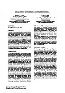
Micromagnetic simulation of a hysteresis loop with Mumax 3.9.1c (CUDA 7000) setGridSize: 64x32x1, Jtot = -3, -6, -9 mA fixed layer polarization = 0 to 90 degrees Spin-torque MRAM stack consisting of a fixed layer, spacer and free layer (2D grid)
Oreci Escobar da Silva (PhD Student) https://www.researchgate.net/profile/Oreci_Da_Silva March 2018
1 Evolution of magnetization: Jtot = -3 mA; 45◦
1
2 Results for the current value = -3 mA
Figure 2.1: angle := 0
Figure 2.2: angle := 1
2
Figure 2.3: angle := 2
Figure 2.4: angle := 3
3
Figure 2.5: angle := 4
Figure 2.6: angle := 5
4
Figure 2.7: angle := 10
Figure 2.8: angle := 15
5
Figure 2.9: angle := 20
Figure 2.10: angle := 30
6
Figure 2.11: angle := 45
Figure 2.12: angle := 60
7
Figure 2.13: angle := 75
Figure 2.14: angle := 90
8
3 Results for the current value = -6 mA
Figure 3.1: angle := 0
Figure 3.2: angle := 1
9
Figure 3.3: angle := 2
Figure 3.4: angle := 3
10
Figure 3.5: angle := 4
Figure 3.6: angle := 5
11
Figure 3.7: angle := 10
Figure 3.8: angle := 15
12
Figure 3.9: angle := 20
Figure 3.10: angle := 30
13
Figure 3.11: angle := 45
Figure 3.12: angle := 60
14
Figure 3.13: angle := 75
Figure 3.14: angle := 90
15
4 Results for the current value = -9 mA
Figure 4.1: angle := 0
Figure 4.2: angle := 1
16
Figure 4.3: angle := 2
Figure 4.4: angle := 3
17
Figure 4.5: angle := 4
Figure 4.6: angle := 5
18
Figure 4.7: angle := 10
Figure 4.8: angle := 15
19
Figure 4.9: angle := 20
Figure 4.10: angle := 30
20
Figure 4.11: angle := 45
Figure 4.12: angle := 60
21
Figure 4.13: angle := 75
Figure 4.14: angle := 90
22
5 License
Mumax3 GPU-accelerated micromagnetic simulator. Copyright (C) 20122014 Arne Vansteenkiste. Contributions by Ahmad Syukri, Colin Jermain, Jonathan Leliaert, Mykola Dvornik. Mumax3 is free software: you can redistribute it and/or modify it under the terms of the GNU General Public License as published by the Free Software Foundation, either version 3 of the License, or (at your option) any later version. This program is distributed in the hope that it will be useful, but WITHOUT ANY WARRANTY; without even the implied warranty of MERCHANTABILITY or FITNESS FOR A PARTICULAR PURPOSE. See the GNU General Public License for more details. Mumax3 uses svgo (http://github.com/ajstarks/svgo), copyright Anthony Starks, licensed under the Creative Commons Attribution 3.0 license as described in http://creativecommons.org/licenses/by/3.0/us/ Mumax3 uses freetype-go (http://code.google.com/p/freetype-go/), copyright Google Inc., Jeff R. Allen, R´emy Oudompheng, Roger Peppe, licensed under the FreeType License or the GNU General Public License (GPL), version 2 or later. Mumax3 uses CUDA libraries, copyright NVIDIA.
23
6 References 1 - Website Mumax: http://mumax.github.io/index.html 2 - MUMAX: A new high-performance micromagnetic simulation tool: https://doi.org/10.1016/j.jmmm.2011.05.037 3 - The design and verification of mumax3: https://doi.org/10.1063/1.4899186 4 - Modelling exchange bias with MuMax3: https://doi.org/10.1088/0022-3727/49/43/435001 5 - Modelling compensated antiferromagnetic interfaces with MuMax3: https://doi.org/10.1088/1361-6463/aa8601 6 - Fast micromagnetic simulations on GPU - recent advances made with mumax 3: https://doi.org/10.1088/1361-6463/aaab1c 7 - License MuMax3: https://github.com/mumax/3/blob/master/LICENSE 8 - GitHub/mumax/3: https://github.com/mumax/3 9 - Spin-transfer torque: https://en.wikipedia.org/wiki/Spin-transfer torque