IEEE TRANSACTIONS ON COMMUNICATIONS, VOL. 59, NO. 7, JULY 2011
1785
MIMO Precoder Selections in Decode-Forward Relay Networks with Finite Feedback Duckdong Hwang, Junil Choi, Bruno Clerckx, and Gil Kim
Abstract—We consider a system with precoding in the half duplex Decode-Forward (DF) relay networks, where multiple antennas are adopted at the source, the destination and the relay. Based on the channel state information (CSI), a few feedback bits are fed back from the destination to the source and the relay to select the source and the relay precoders. A suboptimal precoder selection criterion for the symbol vector error minimization and an optimal precoder selection criterion for the capacity maximization are proposed for the practical situation where relays are placed between the source and the destination. We analyze the diversity performance of the criteria and show that the full diversity is achieved when the rank one precoder sets span the vector channel space formed by the transmit antennas of the source and the those of the relay. Index Terms—MIMO, precoder selection, DF relay network, codebook, diversity.
U
I. I NTRODUCTION
SER cooperation via relaying has drawn much interest recently to enhance the throughput and the reliability of wireless communications [1]–[3]. While several research results [4]–[9] are oriented toward improving the throughput, others [10]–[13] try to enhance the reliability of the wireless channels using the relay. The relation between the reliability and the throughput in the MIMO channels is captured in the diversity-multiplexing trade-off (DMT) analysis of [14]. Authors in [15] present a relaying protocol named dynamic decode forward with superior DMT performance. In practice, simple Amplify-Forward (AF) and Decode-Forward (DF) relaying in half duplex mode transmission are considered [2], [3]. Another important tool to improve the wireless channel transmission is the use of MIMO techniques [16]–[18]. Without the channel state information (CSI) at the transmitter, the space time coding [16], [17] and spatial multiplexing [18] schemes are used. On the other hand, when partial CSI is available at the transmitter, MIMO techniques [19]–[24] enhance the diversity and multiplexing capability at the same time. The diversity and multiplexing performance of relaying can be further enhanced when it is combined with multiple antenna techniques [25]. Beamforming schemes in the AF MIMO relay network are considered in [25]–[27]. In [25], the optimal beamforming condition for the AF MIMO relaying network in the capacity maximizing sense is found. Authors
Paper approved by D. L. Goeckel, the Editor for Space-Time and OFDM of the IEEE Communications Society. Manuscript received January 11, 2010; revised July 12, 2010, October 19, 2010, and February 16, 2010. the authors are with Samsung Electronics Co. (e-mail:
[email protected]). This work is supported by Samsung Electronics Co. Digital Object Identifier 10.1109/TCOMM.2011.050911.100003
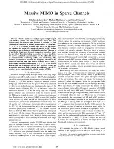
in [26] find the SNR maximizing beamforming method and show that Grassmannian codebook design is optimal. Finally, [27] introduces an antenna selection scheme and analyzes its diversity performance. We consider the DF MIMO relay network with finite feedback from the receiver to the transmitter and the relay. The precoder selection schemes of [21] are extended to DF MIMO relay network when precoding is applied at the source and the relay. Precoders at the source and the relay can be the same or be different. We first derive suboptimal precoder selection schemes for the situations where relays are placed between the source and the destination.1 The criteria consider the minimization of the symbol vector error and the maximization of the mutual information. Then, the conditions to achieve the full diversity in the symbol error probability sense and in the outage probability sense are analyzed for the special case when rank one precoders are applied at the source and the relay. Similar to the traditional MIMO channel in [21], the full diversity is achieved if the set of precoders in the codebook spans the whole vector channel space formed by the transmit antennas at the source and at the relay. This property applies to both the cases of the symbol vector error and of the outage probability senses. The diversity performance analysis shows that the selection criteria work well though they are found based on suboptimal metrics. In Section II, we present the system model for this letter. The precoder selection criteria appear in Section III and Section IV for the symbol vector error sense and the information rate sense respectively. Section V is devoted to the analysis of diversity performance of the proposed criteria. We present simulation results in Section VI and conclude the letter in Section VII. II. S YSTEM M ODEL Figure 1(a) depicts the topology of the MIMO relay network channel. The source, the relay and the destination are equipped with 𝑁𝑠 , 𝑁𝑟 and 𝑁𝑑 antennas respectively. The channel matrices between the nodes are denoted as H0 (𝑁𝑑 × 𝑁𝑠 ), H1 (𝑁𝑟 × 𝑁𝑠 ) and H2 (𝑁𝑑 × 𝑁𝑟 ), where the expressions inside the parenthesis denote the dimensions of the matrices. Let the distance between the source and the destination be 1 and the distance between the source and the relay be 𝑑 (0 ≤ 𝑑 ≤ 1). For convenience, we assume the distance between the relay and the destination is 1 − 𝑑. The elements of the channel matrices are i.i.d. zero mean complex Gaussian random variables, the variances of which are 1, 𝑑𝛼 1 This is the common situation when relays are considered to be used in practice.
c 2011 IEEE 0090-6778/11$25.00 ⃝
1786
IEEE TRANSACTIONS ON COMMUNICATIONS, VOL. 59, NO. 7, JULY 2011
III. P ROBABILITY OF S YMBOL V ECTOR E RROR S ELECTION C RITERIA
Fig. 1. (a) MIMO relay channel topology. (b) Space time transmission block.
and (1 − 𝑑)𝛼 for the elements of H0 , H1 and H2 respectively and 𝛼 is the path loss exponent. Figure 1(b) shows the space time transmission block located in the source and the relay. The information sequence is passed through the error correction coding (ECC) block and serial to parallel mapped before the encoding. For a precoding matrix ˜ is precoded F𝑚 (𝑁𝑠 × 𝑀 ) at the source, the data vector x as x = F𝑚 x ˜. The entries of the precoded information signal vector x = [𝑥1 , 𝑥2 , . . . , 𝑥𝑁𝑠 ]𝑡 are distributed among the 𝑁𝑠 transmit antennas. When we consider symbol vector error criterion, the influence of ECC block is ignored while its role is crucial when the criterion is to maximize the throughput. The feedback information from the destination decides the best precoders that minimize the probability of symbol vector error rate or maximize the throughput. The transmission time is divided into two equal length phases for the half duplex transmissions by the source and the relay. In the first phase, the source node broadcasts x to the relay node and the destination node. We assume the complex encoded signal 𝑥𝑖 has an average power 𝐸[𝑥∗𝑖 𝑥𝑖 ] = 1/𝑁𝑠 . The received signals at the relay and the destination nodes are √ 𝑃 H x + n𝑟 (1) y𝑟 = √ 𝑠 1 𝑃𝑠 H0 x + n𝑑,1 , (2) y𝑑,1 = where 𝑃𝑠 is the transmit power used at the source; the 𝑁𝑟 × 1 vector n𝑟 and 𝑁𝑑 × 1 vector n𝑑,1 are the additive complex Gaussian noise vectors at the relay and the destination nodes respectively. The elements of n𝑟 and n𝑑,1 have unit variances. In the DF protocol, the relay node repeats x with the same transmission chain as Fig 1(b) in the second phase if it succeeds in decoding the message. Otherwise, it remains silent for the second phase. For a precoding matrix G𝑚 (𝑁𝑟 × 𝑀 ) at the relay, the data vector x ˜ is precoded as x ´ = G𝑚 x ˜. The power used in the relay is 𝑃𝑟 . The received signals at the destination node when the relay repeats x is √ ´ + n𝑑,2 , (3) y𝑑,2 = 𝑃𝑟 H2 x where 𝑁𝑑 × 1 vector n𝑑,2 has the same property as that of the vector n𝑑,1 . Based on the channel knowledge (H0 , H1 and H2 )2 , the destination selects the best precoders according to the chosen criterion (symbol vector error or mutual information). The decision on the transmitted data at the destination is made based on y𝑑,1 and y𝑑,2 . 2 For example, the destination can learn the channel information (H and 0 H2 ) by the use of pilot signals at the source and the relay. Using the information of the source pilot, the relay learns the channel H1 and informs the destination of this knowledge through a feed-forward channel.
In this section, we consider the mode selection criteria in the DF MIMO relay networks based on the minimization of symbol vector error (i.e. the event that the reconstructed x ˜ at the receiver is different from the transmitted vector.) probability . The error correction after the decoding of ECC is not accounted. The error event in the DF relay network (let us define this event as ℰ) depends on the error event in the source to relay link (ℰ1 ). With the error in the source to relay link, the error event ℰ occurs when the source to destination link is in error (ℰ0 ) at the same time. Otherwise (ℰ¯1 ), ℰ occurs when the combined link of the source to destination and the relay to destination is in error (ℰ2 ). Hence the event ℰ is composed of ℰ = (ℰ1 ∩ ℰ0 ) ∪ (ℰ¯1 ∩ ℰ2 ). (4) Since the source to relay channel is independent of the source to destination and the relay to destination channels, the error probability is expressed as 𝑃ℰ
= 𝑃ℰ1 𝑃ℰ0 + (1 − 𝑃ℰ1 )𝑃ℰ2 < 𝑃ℰ1 𝑃ℰ0 + 𝑃ℰ2 .
(5)
We have the inequality in (5) since we remove the term 𝑃ℰ1 𝑃ℰ2 with negative sign. If the relay is placed between the source and the destination3, with high probability, 𝑃ℰ1 𝑃ℰ2 becomes the smallest term among the three terms in (5). Hence we argue that the upper bound on the righthand side of (5) is tight in the high SNR and the error rate is dominated by the largest term among 𝑃ℰ1 𝑃ℰ0 and 𝑃ℰ2 . In the scheme we consider, the destination feeds back the indices of the precoders for the source and the relay. Suppose 𝐵1 + 𝐵2 is the number of feedback bits and there are 𝑁1 + 𝑁2 = 2𝐵1 + 2𝐵2 precoding matrices in the code book. The rank of 𝑁1 precoders is less than or equal to 𝑁𝑠 and the rank of 𝑁2 precoders is less than or equal to 𝑁𝑟 . Let 𝑅 be the number of bits transmitted from the source in a unit time. For a MIMO link, the allowable ranks for the precoding matrices in regard to 𝑅 are explained in [21]. The matrix which gives the smallest symbol vector error rate is the preferable precoder. Let the set ℳ = {1, 2, . . . , 𝑁1 } and the precoder matrices (𝑁𝑠 × 𝑀 ) at the source be denoted as F𝑚 , 𝑚 ∈ ℳ, the relation x = F𝑚 x ˜ holds. Using the nearest neighbor union bound (NNUB), the symbol vector error rates of the direct link with channel matrix H0 is upper bounded as [21] ) (√ 𝑃𝑠 𝜆2𝑚𝑖𝑛 (H0 F𝑚 )𝑑2𝑚𝑖𝑛 (𝑀, 𝑅) , 𝑃ℰ0 ≤ 𝑁𝑒 (𝑀, 𝑅)𝑀 𝑄 2𝑀 (6) where 𝜆𝑚𝑖𝑛 (A) is the minimum singular value of the matrix A4 . The variable 𝑁𝑒 (𝑀, 𝑅) denotes the number of nearest neighbors and 𝑑𝑚𝑖𝑛 (𝑀, 𝑅) denotes the minimum distance for the modulation adopted [21]. These variables are functions of 𝑅 and 𝑀 . Similar upper bounds are found for the source to relay link and the relay to destination link. Note the upper bound 3 This
is the most practical deployment scenario. the matrix A is a vector (𝑀 = 1), 𝜆𝑚𝑖𝑛 (A) returns the absolute value of the vector. 4 When
HWANG et al.: MIMO PRECODER SELECTIONS IN DECODE-FORWARD RELAY NETWORKS WITH FINITE FEEDBACK
(𝑚, 𝑘)
= arg
max
𝑚∈ℳ,𝑘∈𝒦
min{2𝜏 (𝑀, 𝑅) + 2 ln(𝑀 ) + 𝑃𝑠 [𝜆2𝑚𝑖𝑛 (H0 F𝑚 ) + 𝜆2𝑚𝑖𝑛 (H1 F𝑚 )] 𝜆𝑚𝑖𝑛 (𝑃𝑠 F†𝑚 H†0 H0 F𝑚 + 𝑃𝑟 G†𝑘 H†2 H2 G𝑘 )
of the symbol vector error in the combined channel of the source to destination and the relay to destination channel (𝑃ℰ2 ) is determined by 𝜆𝑚𝑖𝑛 (𝑃𝑠 F†𝑚 H†0 H0 F𝑚 + 𝑃𝑟 G†𝑘 H†2 H2 G𝑘 ) because the relay simply repeats x ˜ as in (3). Let the set 𝒦 = {1, 2, . . . , 𝑁2 } and the precoder matrices (𝑁𝑟 ×𝑀 ) at the relay be denoted as G𝑘 , 𝑘 ∈ 𝒦. Substituting the upper bounds of (6) and the bounds for the other links into (5) and using 𝑄(𝑥) ≈ 1/2 exp(𝑥2 /2) leads us to the following selection criterion shown in (7), where 𝜏 (𝑀, 𝑅) = ln (𝑁𝑒 (𝑀, 𝑅)/2) and we also use the fact that the summation of probability of errors is dominated by the largest term at high SNR. The metrics for all pairs of precoders are evaluated and the precoder pair (F𝑚 and G𝑘 ) with the maximum metric is selected5 . In the derivation of (7), we take into account the doubled noise power in the combined channel of the source to destination and the relay to destination.
While the data rate 𝑅 is fixed, the minimization of the symbol vector error rate is the main concern of the section III. If we take the effect of ECC into account, the error rate becomes negligible and our interest moves to the maximization of the data rate (𝑅) in the DF relay network. Hence our focus in this section is to develop a precoder(F𝑚) selection criterion that enhances the data throughput 𝑅 of the DF relay network. The information rate ℐ0 (F𝑚 ) of the source to destination link and ℐ1 (F𝑚 ) of the source to relay link are =
ℐ1 (F𝑚 )
=
1 𝑃𝑠 † † log2 ∣I𝑀 + F H H0 F𝑚 ∣, 2 𝑀 𝑚 0 1 𝑃𝑠 † † log2 ∣I𝑀 + F H H1 F𝑚 ∣, 2 𝑀 𝑚 1
𝑑2𝑚𝑖𝑛 (𝑀, 𝑅) }, 4𝑀
𝑑2𝑚𝑖𝑛 (𝑀, 𝑅) , 2𝑀 (7)
the message block, the information rate is ℐ2 (F𝑚 , G𝑘 ). Hence the maximum throughput is given as ℐ(F𝑚 , G𝑘 ) { ℐ0 (F𝑚 ) if ℐ0 (F𝑚 ) ≥ ℐ1 (F𝑚 ) = min[ℐ1 (F𝑚 ), ℐ2 (F𝑚 , G𝑘 )] Otherwise. (11) The optimal criterion for the maximum throughput is given as (𝑚, 𝑘) = arg
max
𝑚∈ℳ,𝑘∈𝒦
ℐ(F𝑚 , G𝑘 ).
(12)
V. D IVERSITY P ERFORMANCE In this section we investigate the diversity performance of the mode selection methods considered in section III and IV. A. Probability of Symbol Vector Error Criteria
IV. I NFORMATION R ATE S ELECTION C RITERIA
ℐ0 (F𝑚 )
1787
(8) (9)
where ∣A∣ is the determinant of the matrix A and 12 reflects the rate loss due to the half duplex relay operation. The information rate of the combined link is 1 𝑃𝑠 † † F H H0 F𝑚 ℐ2 (F𝑚 , G𝑘 ) = log2 ∣I𝑀 + 2 2𝑀 𝑚 0 𝑃𝑟 † † G H H2 G𝑘 ∣, + (10) 2𝑀 𝑘 2 where we assume that the same ECC and the precoder are employed at the source and the relay. The transmission and decoding are done in blocks of data. The block of precoded data vectors is denoted as X = [x1 , x2 , . . . , x𝑇 ], where 𝑇 is the block length. Consider a certain data rate 𝑅. If ℐ1 (F𝑚 ) < 𝑅, the relay fails to decode the message block X and only the source to destination link delivers the information. The information rate of the network is ℐ0 (F𝑚 ) in this case. If ℐ1 (F𝑚 ) ≥ 𝑅 and the relay decodes 5 The tie situation can occur, where multiple pairs having a common F 𝑚 and different G𝑘 ’s with the same metric value in (7). We select an arbitrary pair among these in this case.
For convenience, let us assume the power at the source and the relay satisfy the relation 𝑃𝑟 = 𝑟𝑃𝑠 for a certain constant 𝑟. Then, the diversity order defined in terms of the probability of error rate as d = − lim
𝑃𝑠 →∞
log 𝑃ℰ (𝑃𝑠 ) , log 𝑃𝑠
(13)
is an asymptotic performance measure. To show the diversity performance of the precoding matrix selection schemes of section III, we consider the precoding matrices of rank one case. Let us denote f𝑚 , 𝑚 = 1, 2, . . . , 𝑁1 be the rank one precoding vectors at the source and g𝑘 , 𝑘 = 1, 2, . . . , 𝑁2 be the rank one precoding vectors at the relay. Then, equation (7) becomes (14), where we use the fact that the singular value of a vector is the squared norm of the vector. At high SNR, 2𝜏 (1, 𝑅)/𝑑2𝑚𝑖𝑛 (1, 𝑅) becomes negligible and we are left with (15). Lemma 1 states the condition to achieve the full diversity order in (15). Lemma 1: The criterion (15) achieves the maximum diversity of 𝑁𝑠 𝑁𝑑 +𝑁𝑟 min[𝑁𝑠 , 𝑁𝑑 ] if the following two conditions are met. condition 1) The number of rank one precoders (f𝑚 , 𝑚 ∈ ℳ) at the source is greater than or equal to 𝑁𝑠 (i.e 𝑁1 ≥ 𝑁𝑠 ) and the rank of the matrix F = [f1 , . . . , f𝑁1 ] is 𝑁𝑠 . condition 2) The number of rank one precoders (g𝑘 , 𝑘 ∈ 𝒦) at the relay is greater than or equal to 𝑁𝑟 (i.e 𝑁2 ≥ 𝑁𝑟 ) and the rank of the matrix G = [g1 , . . . , g𝑁2 ] is 𝑁𝑟 . Proof: Let F = V† ΛU and G = M† ΣP be the singular value decomposition (SVD) of F and G respectively, where6 V = [v1 , . . . , v𝑁𝑠 ], Λ = 𝑑𝑖𝑎𝑔(𝜆1 , . . . , 𝜆𝑁𝑠 ) U = [u1 , . . . , u𝑁1 ] and M = [m1 , . . . , m𝑁𝑟 ], Σ = 𝑑𝑖𝑎𝑔(𝜎1 , . . . , 𝜎𝑁𝑟 ) P = [p1 , . . . , p𝑁2 ]. 6 For convenience, we use slightly different SVD notation, where the leftmost unitary matrix is Hermitian transposed.
1788
IEEE TRANSACTIONS ON COMMUNICATIONS, VOL. 59, NO. 7, JULY 2011
(𝑚, 𝑘) = arg
max
𝑚∈ℳ,𝑘∈𝒦
(𝑚, 𝑘) = arg
min{
max
2𝜏 (1, 𝑅) + 𝑃𝑠 ∥H0 f𝑚 ∥2 + 𝑃𝑠 ∥H1 f𝑚 ∥2 , 𝑃𝑠 ∥H0 f𝑚 ∥2 /2 + 𝑃𝑟 ∥H2 g𝑘 ∥2 /2} 𝑑2𝑚𝑖𝑛 (1, 𝑅)
𝑚∈ℳ,𝑘∈𝒦
min{𝑃𝑠 ∥H0 f𝑚 ∥2 + 𝑃𝑠 ∥H1 f𝑚 ∥2 , 𝑃𝑠 ∥H0 f𝑚 ∥2 /2 + 𝑃𝑟 ∥H2 g𝑘 ∥2 /2}
The singular values are numbered in descending order. The terms in (15) are represented as 𝑑
max ∥H𝑖 f𝑚 ∥ = max ∥H𝑖 Λu𝑞 ∥,
𝑚∈ℳ
𝑞∈ℳ
𝑑
max ∥H𝑖 g𝑘 ∥ = max ∥H𝑖 Σpℓ ∥, 𝑘∈𝒦
ℓ∈𝒦
(16)
𝑑
for 𝑖 = 0, 1, 2. Here, = denotes equivalence in distribution. Then, the metric in (15) has the same distribution as (17), where ℎ𝑖𝑝,𝑞 is the magnitude of the (𝑝, 𝑞) entry of the matrix H𝑖 and ∥A∥𝐹 denotes the Frobenius norm of A. The first lower bound comes from the fact that the codebook matrices F and G are full rank and the max operator makes the value of individual term be lower bounded when u𝑞 and pℓ are ones among e𝑗 , 𝑗 = 1, . . . , (𝑁𝑠 or 𝑁𝑟 ), where e𝑗 is the unit vector with one ∑ in the 𝑗-th position and all zeroes in (𝑁 or 𝑁𝑟 ) ∥Ae𝑗 ∥2 = ∥A∥2𝐹 , the first other positions. Since 𝑗=1𝑠 inequality in (17) holds. The terms max𝑝≤𝑁𝑑 ,𝑞≤𝑁𝑠 ∥ℎ0𝑝,𝑞 ∥2 , max𝑝≤𝑁𝑠 ,𝑞≤𝑁𝑠 ∥ℎ1𝑝,𝑞 ∥2 and max𝑝≤𝑁𝑑 ,𝑞≤𝑁𝑠 ∥ℎ2𝑝,𝑞 ∥2 in (17) are known to have diversity orders of 𝑁𝑠 𝑁𝑑 , 𝑁𝑠 𝑁𝑟 and 𝑁𝑟 𝑁𝑑 respectively when 𝑁𝑟 = 𝑁𝑠 . Because of the minimum operator in (17), the total diversity order is lower bounded by 𝑁𝑠 𝑁𝑑 + 𝑁𝑟 min[𝑁𝑠 , 𝑁𝑑 ]. Note that this is the maximum diversity order achievable in the given antenna and network configuration. Hence 𝑁𝑠 𝑁𝑑 + 𝑁𝑟 min[𝑁𝑠 , 𝑁𝑑 ] is the diversity order attained. When 𝑁𝑠 = 𝑁𝑟 , we can apply the same precoder at the source and the relay. Certainly, using different precoders at different nodes gives more room for performance enhancement, but it needs more complicated feedback strategy and an additional codebook. We compare the performance of these two options in section VI.
For the diversity performance of the information rate maximizing precoder selection, the outage probability event is used. The outage event (𝒪) is defined for a certain rate requirement 𝑅 and a precoder F𝑚 as ℐ(F𝑚 ) < 𝑅. Then, the diversity in terms of the probability of outage (𝑃𝒪 (𝑃𝑠 )) is similarly defined as in (13), where 𝑃𝒪 (𝑃𝑠 ) substitutes 𝑃ℰ (𝑃𝑠 ). For the same reasoning as in section III, the outage probability is bounded as 𝑃𝒪
= 𝑃𝒪1 𝑃𝒪0 + (1 − 𝑃𝒪1 )𝑃𝒪2 < 𝑃𝒪1 𝑃𝒪0 + 𝑃𝒪2 ,
(18)
where 𝑃𝒪𝑖 = 𝑃 (ℐ𝑖 < 𝑅), 𝑖 = 0, 1, 2. Since the optimal criterion in (12) maximizes the information rate ℐ, it minimizes the outage probability at the
(15)
same time. It is hard to show the outage performance using equation (12), hence we use the criterion in (15) to show the diversity performance of the outage. Then, the criterion becomes sub-optimal in the information rate maximization sense. The diversity order of this sub-optimal criterion lower bounds that of the optimal scheme. Lemma 2 states that (15) achieves the full diversity in outage probability sense also with the same condition as in lemma 1. Lemma 2: For the same conditions as in lemma 1, the criterion in (15) achieves diversity order of 𝑁𝑠 𝑁𝑑 + 𝑁𝑟 min[𝑁𝑠 , 𝑁𝑑 ] in the outage probability sense. Proof: Since we are using the criterion in (15), we have the same statistics and the same lower bound as in (17). We only need to show that each term in (17) has the same diversity order in the outage probability sense as that in the symbol error probability sense. Equation (8) becomes in the rank one precoder case 1 log2 (1 + 𝑃𝑠 ∥H0 f𝑚 ∥2 ). (19) 2 For the SVD of F = V† ΛU, we have 1 max ∥H𝑖 Λu𝑞 ∥2 ≥ ∥H𝑖 Λ∥2𝐹 𝑞∈ℳ 𝑁𝑠 𝜆2 ≥ 𝑁𝑠 max ∥ℎ𝑖 ∥2 , 𝑖 = 0, 1, 2. 𝑁𝑠 𝑝≤𝑁𝑑 ,𝑞≤𝑁𝑠 𝑝,𝑞 (20) ℐ0 (f𝑚 ) =
Therefore, the outage probability of the source to the relay link is 𝑃𝒪0 = 𝑃 (ℐ0 < 𝑅) = 𝑃 (∥H0 f𝑚 ∥2 < ≤ 𝑃(
B. Information Rate Criteria
(14)
𝜆2𝑁𝑠 𝑁𝑠
max
22𝑅 − 1 ) 𝑃𝑠
𝑝≤𝑁𝑑 ,𝑞≤𝑁𝑠
∥ℎ𝑖𝑝,𝑞 ∥2