Nov 23, 2015 - 4.3.2 The Android Streams Designer . .... D.1.6 ProcessStream . ..... Figure 1.6 illustrates the overall structure of the thesis and the ...
Mining Big Data Streams for Multiple Concepts
Dissertation zur Erlangung des Grades eines
Doktors der Ingenieurwissenschaften der Technischen Universit¨at Dortmund an der Fakult¨at f¨ ur Informatik von Christian Bockermann
Dortmund 2015
Tag der m¨ undlichen Pr¨ ufung: Dekan: Gutachter:
23. November 2015 Prof. Dr.-Ing. Gernot A. Fink Prof. Dr. Katharina Morik Dr. Albert Bifet
Contents I
Fundamentals
1 Introduction 1.1 The Lambda Architecture . . . . . . . . . . . . . . . 1.2 Objectives of this Thesis . . . . . . . . . . . . . . . . 1.2.1 Requirements of Big Data Application Design 1.2.2 Objectives addressed in this Thesis . . . . . . 1.2.3 Indicators and Evaluation Criteria . . . . . . 1.3 Outline . . . . . . . . . . . . . . . . . . . . . . . . . 1.4 Applications and Publications . . . . . . . . . . . . . 1.4.1 Publications Covered by this Thesis . . . . . 1.4.2 Projects and Publications beyond the Thesis
9 . . . . . . . . .
. . . . . . . . .
. . . . . . . . .
. . . . . . . . .
. . . . . . . . .
11 13 15 16 17 19 20 21 21 23
2 Stream Processing Survey 2.1 Emerging Streaming Platforms . . . . . . . . . . . . . . . . . . 2.1.1 Evolvement of General Purpose Streaming Frameworks 2.2 An Abstract View on Stream Processing . . . . . . . . . . . . . 2.2.1 Requirements of General Purpose Streaming Platforms . 2.2.2 Usability and Process Modelling . . . . . . . . . . . . . 2.2.3 Features of Modern Streaming Platforms . . . . . . . . 2.3 General Purpose Streaming Platforms . . . . . . . . . . . . . . 2.3.1 Queueing and Message Passing . . . . . . . . . . . . . . 2.3.2 Stream Execution Engines . . . . . . . . . . . . . . . . . 2.4 Stream Processing Frameworks . . . . . . . . . . . . . . . . . . 2.4.1 Apache Storm . . . . . . . . . . . . . . . . . . . . . . . 2.4.2 Apache Samza . . . . . . . . . . . . . . . . . . . . . . . 2.4.3 S4 – Distributed Stream Computing Platform . . . . . . 2.4.4 MillWheel . . . . . . . . . . . . . . . . . . . . . . . . . . 2.4.5 Stratosphere / Apache Flink . . . . . . . . . . . . . . . 2.5 Summary . . . . . . . . . . . . . . . . . . . . . . . . . . . . . . 2.5.1 Comparison of Stream Processing Engines . . . . . . . . 2.5.2 The Feature Radar . . . . . . . . . . . . . . . . . . . . .
. . . . . . . . . . . . . . . . . .
. . . . . . . . . . . . . . . . . .
. . . . . . . . . . . . . . . . . .
. . . . . . . . . . . . . . . . . .
27 28 30 31 32 33 34 35 36 40 44 44 47 50 51 54 56 56 61
. . . . . . . . .
. . . . . . . . .
. . . . . . . . .
. . . . . . . . .
. . . . . . . . .
3 The streams Framework 63 3.1 A Framework for Integrated Process Design . . . . . . . . . . . . . . . 64
5
Contents
3.2
3.3
3.4
3.5
3.1.1 Objectives of the streams Approach . . . . . . . . 3.1.2 Platform Independence and Code Re-use . . . . 3.1.3 Executing Abstract Data Flow Graphs . . . . . . Abstraction of Application Modelling . . . . . . . . . . . 3.2.1 Representation of Data and Streams of Data . . 3.2.2 Streaming Functions for Data Items . . . . . . . 3.2.3 Processes and Data Flow . . . . . . . . . . . . . 3.2.4 A Service Layer for Anytime Accessibility . . . . Realization of the streams Architecture . . . . . . . . . . 3.3.1 Designing Streaming Applications in XML . . . . 3.3.2 A Programming API for Streaming Applications 3.3.3 The streams Runtime Implementation . . . . . . 3.3.4 Compiling to other Streaming Platforms . . . . . Extensions of the streams Framework . . . . . . . . . . . 3.4.1 Using Scripting Languages in streams . . . . . . 3.4.2 Integration of the MOA Library . . . . . . . . . Summary . . . . . . . . . . . . . . . . . . . . . . . . . .
. . . . . . . . . . . . . . . . .
. . . . . . . . . . . . . . . . .
. . . . . . . . . . . . . . . . .
. . . . . . . . . . . . . . . . .
. . . . . . . . . . . . . . . . .
. . . . . . . . . . . . . . . . .
. . . . . . . . . . . . . . . . .
. . . . . . . . . . . . . . . . .
66 67 68 69 71 73 74 76 78 78 88 96 97 103 103 105 110
4 User Guided Process Design 111 4.1 Visual Programming . . . . . . . . . . . . . . . . . . . . . . . . . . . . 113 4.1.1 Gesture-based Process Design . . . . . . . . . . . . . . . . . . . 115 4.1.2 Cognitive Dimensions of Visual Programming . . . . . . . . . . 116 4.2 A Sketch Approach to the Design of Applications . . . . . . . . . . . . 119 4.2.1 Symbolification of Data Flow Patterns . . . . . . . . . . . . . . 120 4.2.2 Recording User Interactions for Gesture Detection . . . . . . . 123 4.2.3 Machine Learning for Gesture Recognition . . . . . . . . . . . . 124 4.2.4 Evaluation of Features and Classifiers for Gesture Recognition 130 4.3 An Application to streams and RapidMiner . . . . . . . . . . . . . . . 135 4.3.1 The RapidMiner Artist Application . . . . . . . . . . . . . . . 136 4.3.2 The Android Streams Designer . . . . . . . . . . . . . . . . . . 138 4.4 Summary . . . . . . . . . . . . . . . . . . . . . . . . . . . . . . . . . . 143
II
Applications
5 Analyzing Telescope Data 5.1 Data Analysis Problems in Gamma-Ray Astronomy . . . 5.1.1 From Raw Data Acquisition to Spectral Analysis . 5.1.2 Signal Separation and Energy Estimation . . . . . 5.1.3 The Interdisciplinary Gap in Process Development 5.2 FACT-Tools: Processing Telescope Data with streams . . 5.2.1 The FACT Tools Library . . . . . . . . . . . . . . 5.2.2 Defining FACT Analysis Chains . . . . . . . . . . 5.2.3 Integrating WEKA for Online Classification . . . .
6
145 . . . . . . . .
. . . . . . . .
. . . . . . . .
. . . . . . . .
. . . . . . . .
. . . . . . . .
. . . . . . . .
147 148 150 151 154 155 156 159 163
Contents 5.3
. . . . . . . . .
. . . . . . . . .
. . . . . . . . .
. . . . . . . . .
. . . . . . . . .
165 165 167 169 169 170 172 174 177
6 Video Stream Analysis 6.1 Analysis of Heterogeneous Data . . . . . . . . . . . 6.1.1 Combining Data in IP-TV . . . . . . . . . . 6.1.2 Heterogeneous Data in Physics . . . . . . . 6.2 Processing Video Streams with streams-video . . . 6.2.1 Reading Video Streams . . . . . . . . . . . 6.2.2 Counting Objects in Video Streams . . . . 6.2.3 Detecting Advertising in IP-TV . . . . . . . 6.3 Aggregating Data Streams . . . . . . . . . . . . . . 6.3.1 A Simple Publish-Subscriber Architecture . 6.3.2 Joining External Data . . . . . . . . . . . . 6.3.3 Aggregating Statistics using Complex Event 6.4 Summary . . . . . . . . . . . . . . . . . . . . . . .
. . . . . . . . . . . . . . . . . . . . . . . . . . . . . . . . . . . . . . . . . . . . . . . . . . . . . . . . . . . . . . . . . . . . . . Processing . . . . . . .
. . . . . . . . . . . .
. . . . . . . . . . . .
. . . . . . . . . . . .
. . . . . . . . . . . .
179 181 182 183 184 184 192 196 198 198 203 207 212
7 Summary and Conclusion 7.1 Summary . . . . . . . . . . . . . . . . 7.2 Conclusions and Impact of this Thesis 7.2.1 Conclusions . . . . . . . . . . . 7.2.2 Impact of this Thesis . . . . . . 7.3 Outlook and Future Work . . . . . . .
. . . . .
. . . . .
. . . . .
. . . . .
. . . . .
213 214 216 216 218 220
5.4
5.5
Data Analysis with the FACT Tools . . . . . . . . . . . . . 5.3.1 Gamma/Hadron Separation with Machine Learning 5.3.2 Throughput Performance of the FACT-Tools . . . . FACT in the Context of Map&Reduce . . . . . . . . . . . . 5.4.1 Distributing Code to Data . . . . . . . . . . . . . . . 5.4.2 Storing FACT Data in HDFS . . . . . . . . . . . . . 5.4.3 Mapping streams Functions to Apache Hadoop . . . 5.4.4 Performance Evaluation of streams-mapred . . . . . Summary . . . . . . . . . . . . . . . . . . . . . . . . . . . .
. . . . .
. . . . .
. . . . .
. . . . .
. . . . .
. . . . .
. . . . .
. . . . .
. . . . .
. . . . .
. . . . .
. . . . . . . . .
. . . . .
. . . . .
III Appendix
223
A Overview of Collaborative Works
225
B Sample Code 227 B.1 Coffee Capsule Detection . . . . . . . . . . . . . . . . . . . . . . . . . 227 C The streams Framework 231 C.1 Extending the streams Framework . . . . . . . . . . . . . . . . . . . . 231 C.1.1 Implementing Custom Data Streams . . . . . . . . . . . . . . . 231 C.1.2 Implementing Custom Processors . . . . . . . . . . . . . . . . . 235 D The streams-core Package
239
7
D.1 The streams-core Data Streams . . . . . . . . D.1.1 ArffStream . . . . . . . . . . . . . . . D.1.2 CsvStream . . . . . . . . . . . . . . . D.1.3 JSONStream . . . . . . . . . . . . . . D.1.4 LineStream . . . . . . . . . . . . . . . D.1.5 SQLStream . . . . . . . . . . . . . . . D.1.6 ProcessStream . . . . . . . . . . . . . D.1.7 TimeStream . . . . . . . . . . . . . . . D.2 The streams-core Queues . . . . . . . . . . . . D.2.1 BlockingQueue . . . . . . . . . . . . . D.3 The streams-core Processors . . . . . . . . . . D.3.1 Processors in Package stream.flow . D.3.2 Processors in Package stream.data . D.3.3 Processors in Package stream.parser D.3.4 Processors in Package stream.script
. . . . . . . . . . . . . . .
. . . . . . . . . . . . . . .
. . . . . . . . . . . . . . .
. . . . . . . . . . . . . . .
. . . . . . . . . . . . . . .
. . . . . . . . . . . . . . .
. . . . . . . . . . . . . . .
. . . . . . . . . . . . . . .
. . . . . . . . . . . . . . .
. . . . . . . . . . . . . . .
. . . . . . . . . . . . . . .
. . . . . . . . . . . . . . .
. . . . . . . . . . . . . . .
. . . . . . . . . . . . . . .
239 240 240 241 242 243 244 244 245 245 246 247 251 253 255
E The streams-video Package E.1 The streams-video Data Streams . . . . . . . . . . . . E.1.1 Video Stream Implementations . . . . . . . . . E.1.2 Audio Stream Implementations . . . . . . . . . E.2 The streams-video Processors . . . . . . . . . . . . . . E.2.1 Processors in Package stream.image . . . . . . E.2.2 Processors in Package stream.image.features
. . . . . .
. . . . . .
. . . . . .
. . . . . .
. . . . . .
. . . . . .
. . . . . .
. . . . . .
. . . . . .
257 257 257 258 259 259 261
Part I.
Fundamentals
9
Chapter 1 Without big data analytics, companies are blind and deaf, wandering out onto the web like deer on a freeway. – Geoffrey Moore, author and consultant.
Introduction
Over the past years Big Data has become the predominant term of our information system era. Gaining knowledge from massive amounts of data is regarded one of the key challenges of our times. Starting with the problem to process the immense volume of data, Big Data has emerged additional properties: the variety of different types of data and the velocity in which new data is being produced. This is often referred to as the 3 V ’s of the Big Data challenge [100]: • Volume: the ability to process data in the range of terabytes and petabytes • Variety: the need to combine data from all kinds of different sources and formats • Velocity: the ability to keep up with the immense speed of generated data. Two fundamental aspects have changed in the data we are facing today, requiring the paradigm shift that makes it Big Data: The sizes of data sets have grown to amounts intractable by existing batch approaches, and the rate at which data changes demands for short-term reactions to data drifts and updates of the models describing the data. The shear volume of data demands for highly scalable platforms that provide huge storage capacities in a distributed setting. The progressing decrease of the lifetime of our data additionally demands for analytical processes that produce continuous results in near real-time. The volume problem of big data has generally been addressed by massive parallelism. With the drop of hardware prizes and evolving use of large cloud setups, computing farms are deployed to handle data at a large scale. Though parallelism and concepts
11
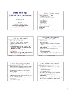
1. Introduction for cluster computing have been studied for long, their applicability was mostly limited to specific use cases. One of the most influential works to use computing clusters in data analysis is probably Google’s revival of the map-and-reduce paradigm [57]. The concept has been around in functional programming for years and has now been transported to large-scale cluster systems consisting of thousands of compute nodes. Apache’s open-source Hadoop [54] implementation of a map-and-reduce platform nowadays builds the foundation for various large-scale systems and has become the de-facto standard for Big Data processing with open-source systems. In [129] Sakr, Liu and Fayoumi survey the family of MapReduce systems along with their improvements. Emerged from the Hadoop platform has the Zookeeper cluster management sub-project [2]. Zookeeper is a fault-tolerant, distributed coordination service that has become one of the key core-components of modern distributed scale-out platforms. Recently, a new project called Mesos [83] has been proposed for abstacting cluster resource management, which might become a replacement for Zookeeper. From Batches to Continuous Streams Whereas the volume and variety have been the first encounters of the Big Data era, the need to address the velocity of data processing has become more and more important: As data is generated at higher speed, the validity of data is a quickly decreasing quality. For a very simple example, one may look at text data – long-term static web pages have been supplanted by more up-to-date weblogs. With blogging systems people started providing much more frequent updates, which have then been superseeded by micro-blogging in the form of twitter messages or status updates in social media. Where static pages had a validity of months or years, blogging pushed that periods down to days or weeks. The validity of twitter messages is often much less than days. As a result, the processing of data needs to keep up with that evolvement of data and any results computed in today’s systems must reflect that. Following the blog example, in mid 2010 Google changed its indexing system from pure batch-wise
Web Pages
Blogs
Twitter
2008
2010
2014
Map&Reduce
Caffeine
MillWheel
Figure 1.1.: Transition of technologies towards real-time processing for search results within Google to match up the decreasing life time of information.
12
1.1. The Lambda Architecture indexing to online updates of the search index in order to provide search results that reflect articles found within the last 10 or 15 minutes [3]. Figure 1.1 shows the different software systems used by Google over the past years. Another example can be found in Formula 1 racing: Modern racing cars are equipped with hundreds of telemetric sensors that measure brake temperature, fuel consumption, provide video data of tyres (to derive tyre temperature and outwear) and so on. This telemetric data plays such an important role, that it has become part of the official regulations in Formula 1. The use of data analysis in Formula 1 is diverse: From air tunnel simulations in the car construction phase (ahead of pre-season) to testing rides of the constructed car (pre-season) to realtime optimization of the car’s fine tuning during the race (season). While racing, the telemetric data is transmitted in near-realtime to the pit lane center at the track with a delay in the range of milliseconds. The radio transmission of the telemetric data is handled by custom technology especially developed for the lowlatency transmission from high speeding cars. The data is further transmitted to the team’s data centers for realtime analysis. The analytical results are then used to optimize the engine (e.g. ignition timings) or give hints to the driver on where and how he can gain speed and decrease the lap time. Therefore, the analysis needs to be performed online to be able to apply the optimization right within the race. The software techniques used within Formula 1 racing range from Map-Reduce cluster computation (e.g. simulation data) to distributed stream processing (realtime racing data). Racing teams like Red Bull Racing partner with SAP [137] to make use of SAP’s HANA in-memory database and deploy Apache Hadoop clusters or NoSQL databases to still their analysis demands in time.
1.1. The Lambda Architecture Looking at a generic picture of today’s data applications, it is rather common to have data that is produced by some process (e.g. customers shopping) being stored in a database. Running analytical processes will reveal some sort of results, e.g. a daily report or a prediction model for future purchases (e.g. to improve pre-ordering). Figure 1.2 below outlines this scheme. Data (continuous)
Database
Batch Process
Results
Figure 1.2.: A generic outline of an data oriented application.
13
1. Introduction This generic architecture poses two problems, which arise when (a) data volume increases and (b) the results being required to reflect even the last minute data that most recently arrived. In the last section we briefly outlined two real world examples. The Lambda Architecture is a term that has first been defined by Nathan Marz in [109]. The central observation is that the answer to a query (e.g. financial report, prediction model,...) is a result computed from all the data that is available: result = query(all data). Computing the results by a (massively parallelized) batch job does produce a response with a significant delay, but does not include the data that has been collected in the period from starting the batch job to its completion. Therefore, the generic application scheme of Figure 1.2 does not meet todays data demands. Even the computation of an index, that provides the basis for ad-hoc computation of the final results does not solve this. The Lambda Architecture as proposed by Marz therefore introduces three basic components for designing Big Data software systems: The traditional batch layer, the serving layer and the speed layer. Where the batch layer handles the execution of long-term jobs on history data, it typically produces intermediate results for computing the final query response. These intermediate outcomes are stored within the serving layer such that they can be queried in real-time. To bridge the gap between the continuous data that needs to be incorporated into the final query outcome, the speed layer is introduced as a streaming approach that will compute online results and feed these back into the service layer. Queries to the system are answered by aggregating intermediate results from the serving layer. Figure 1.3 shows the three components of the lambda architecture: Serving Layer
λ Speed Layer
Batch Layer
Figure 1.3.: The components of the Lambda Architecture.
Simply by building a software system using these guiding component layout does not meet the requirements of Big Data per se. The implementation of each of the
14
1.2. Objectives of this Thesis layers needs to be scalable to a large amount of computing nodes and requires loosely coupled fault tolerant components to be in place. The aforementioned Apache Hadoop system serves as an example for the batch layer. It provides large scale distributed storage and execution of batch jobs. Software such as Apache Cassandra [98], Google BigTable [46] or the distributed full-text index ElasticSearch set the scene to implement a serving layer within a Big Data system. The speed layer may be provided by streaming platforms such as Apache Storm [61], Apache Samza [4], Google’s MillWheel [12] or others.
1.2. Objectives of this Thesis The design and implementation of a Big Data infrastructure requires in-depth knowledge and careful planning. With the lack of an exact definition of Big Data, an interesting view on the term was given by Albert Bifet in a statement during his visit at the SFB 876 Topical Seminar: “Big Data problems are those, which are not solvable with standard off-theshelf software systems.” Albert Bifet, October 2013.
The volume, variety and velocity of data pose challenges to the Big Data platform design which are focusing on the performance of the system. Scaling up a system to the demands of Big Data is a task that requires careful optimization and adaption of algorithms with a direct integration of the distributed nature, keeping data locality and network design in mind. This implies a highly specifalized implementation of a system architecture for each application domain. A few principles and building blocks to design such applications have been identified in the Lambda Architecture. The large scale systems that may be used for implementing any of the layers within the Lambda Architecture require sophisticated tuning to be adapted to specific application tasks. Figure 1.4 shows the triangle of different aspects that form the challenges of designing software systems to tackle Big Data tasks. Complexity of Applications
Big Data Volumes
Ressource Limitations
Figure 1.4.: Three fundamental aspects of the challenges that Big Data poses to modern application development.
15
1. Introduction
1.2.1. Requirements of Big Data Application Design The major aspect in Big Data applications has been tackled by several software platforms: The distributed scale up to a huge number of nodes that empower the large scale software systems. With the scaling factor comes a considerable new aspect: the rising complexity of the now distributed applications. New programming paradigms and concepts are introduced and the ways in which developers need to think about application design are subject to change. This complexity increases the resources required to design and build Big Data applications in terms of development costs. Considering the development of Big Data systems, we further investigate the following areas:
Usability
Multi-Paradigm
Rapid Prototyping
Platform Independence
Though these aspects have found their advocates in traditional software development, Big Data often is focused on pure scalability and robustness. Opening Big Data techniques to end-users requires careful consideration on these facets. Usability Gap A leading question is the applicability of modern Big Data technologies by domain experts. The increased complexity of these distributed applications demands for extensive combined knowledge of the architecture and the application domain. Often, these extensive skills are not present in the area of domain experts. We refer to this situation as the usability gap – the techniques and architecture of Big Data are not directly usable by application experts and require considerable efforts to be used. The usability gap is a Big Data aspect that has not yet received much attention. Platform Independence A more technical aspect, that in some sense is related to the usability gap is the quickly evolving landscape of Big Data techniques. As the evolution of the platforms comes with various improvements of computational speed, management or scalability features, it challenges end users with the question on which platform to use. Each
16
1.2. Objectives of this Thesis of the software systems usually builds upon a proprietary API that results in applications being implemented with a single target platform in mind. The ultimate commitment to a specific platform inherits several risks to end-users: With the quick evolution of the software landscape, users may end up with platforms that are no longer maintained; a specific platform may turn out not to be fully suited for the applications needs; or it will be hard to set up the application in a different setting (i.e. on smaller, non-distributed scale). Multi-Paradigm Design Where the platform independence aims at running some implemented application on different engines of the same kind (e.g. streaming engine), the Big Data world fosters the use of different paradigms for application design. The Lambda Architecture itself inherits three different approaches: flow-based streaming applications, map-reduce like batch processing and a service oriented query-system. Interestingly, none of these paradigms is new: Flow-based programming [112, 111] has been around since the 1970s; the map-reduce principle was already prominent in the old days of LISP or other functional programming languages. The Big Data era now revitalises some of these concepts in new distributed computing contexts and requires their combination within a global application design. An approach for defining applications for Big Data in a larger context should aim at supporting as many of these paradigms as possible with as few code changes as possible. Rapid Prototyping and Extensibility From an application designer perspective, the typical applications have moved from a static set of features to evolving modules – especially the use of Big Data in scientific areas therefore demands quick adaption of applications to new findings or insights gained from previous analysis processes. This needs to be reflected when trying to bridge the usability gap mentioned above: new approaches to Big Data application design need to support the end-user mindset as well as a quick and flexible (declarative) modelling of applications. The integration of existing libraries as well as the combination with other platforms is required to embed an application into the complex environment of a Big Data architecture. A proper level of abstraction is therefore required to model applications in a flexible way by the use of existing software components.
1.2.2. Objectives addressed in this Thesis The need for data analysis in the Big Data area has spawned a development that grows beyond the traditional machine learning research and methods being tested on small data sets such as the UCI Machine Learning Repository [6]: Data analysis needs to be directly implemented within the Big Data architectures. This requires the creation of applications that reflect the complete cycle from data acquisition,
17
1. Introduction Big Data Analytics “UCI Machine Learning”
Data Acquisition
Filtering
Feature Extraction
Modelling
Optimizations Predictions
Insights
Figure 1.5.: The outreach of data analysis within Big Data. pre-processing, and feature extraction to the training and application of models for prediction, process parameter optimization or new insights that support the business understanding, as shown in Figure 1.5. This thesis addresses the usability gap and application design of Big Data streaming applications. The goal of this thesis is to bridge the gap between distributed (and non-distributed) data stream processing and its adaptability in different application domains. The core contribution is an abstract data stream processing framework, named streams, which inherently considers the aforementioned Big Data modelling requirements with a strong emphasis on usability and extensibility. The following core objectives define the setting in which we developed the streams platform: (1) Usability Providing high-level application modelling with different modules, heterogenous data sources, while keeping the coding level part as low as possible. (2) Platform Independence Aiming at the design of streaming applications with small and large scale architectures (e.g. Raspberry PI vs. Apache Storm). (3) Multi-Paradigm Support Abstraction of concepts, which allow for mapping applications to different environments (Map&Reduce as well as streaming). (3) Rapid Prototyping Providing third party library integration into the declarative application modelling and allowing for easy integration of custom code. The streams system as proposed in this thesis is an abstract framework for the modelling of data flows as streaming applications. These abstract data flow graphs can be compiled to different execution engines. By providing a declarative application modelling, it enables users to define multiple connected processes and services. The layer of abstraction defined by the streams platform targets the needs of the domain expert users’ to define data processes while deliberating them from the complexity of large scale distributed environments as much as possible.
18
1.2. Objectives of this Thesis Among the easy orchestration of applications using the streams approach, we use the abstraction step inherent to streams to support a multi-paradigm design, which maximizes the code re-use even among different programming paradigms. By easily lifting external libraries to the abstract layer of streams we allow for the simple inclusion of existing software libraries directly into the application modelling. This features an inherently extensible platform. To facilitate the application design in a rapid prototyping manner, the streams approach uses a declarative application design, that allows for defining an application by its data flow. The declarative nature of the approach eases the modelling of applications for domain experts as it minimises the need to write program code.
1.2.3. Indicators and Evaluation Criteria As the design of the streams framework has been motivated with the guiding principles listed above, we will now develop a set of measurements to ensure the compliance of the framework with these criteria. Obviously, the aforementioned objectives like usability, rapid prototyping or code re-use are hard to assess in qualitative numbers or ratings. User feedback to evaluate usability is one approach, but only provides reasonable insights when focusing in a very specific aspect, e.g. parts or concepts within a particular user interface. Especially the power inherited by the abstraction principle is hard to evaluate with user feedbacks or a questionnaire. We set out the following criteria for a placement of streams within the continuum of the Big Data landscape: (E.1) Platform Independence The modelling of streaming applications for multiple execution engines. (E.2) Code Re-Use The extent to which domain specific code can be re-used without any or only little modifications. (E.3) Abstract Modelling The degree to which domain experts can design their application data flows without the need to compile code or deal with programming interfaces. (E.4) Extensibility The ease of adapting the framework to new application domains. (E.5) Speed/Performance The extent to which the abstract application specification can be fine tuned to gain the maximum performance with respect to different requirements. The criteria (E.1) to (E.3) are targeted to assess the power of abstraction that comes with the proposed streams framework. The extensibility (E.4) investigates the versatility and flexibility of streams within different application domains and contexts. The execution platform provided by streams itself is the objective in criterium (E.5), where we compare the performance of an application in different execution engines.
19
1. Introduction
1.3. Outline The thesis is divided into two parts: The first part covers an in-depth overview of the current state of the art regarding general purpose streaming systems and introduces the streams framework as a light-weight middle layer abstraction to streaming platforms. For each of the evaluation criteria, we will discuss their conceptual adherence when describing the streams approach and the modelling user interface experiments we performed. The second part deals with the evaluation of streams with regard to the indicating properties E.1 through E.5. For this we investigate several real-world examples where we used the framework and show its versatility by outlining its use in typical scenarios of Big Data processing. Figure 1.6 illustrates the overall structure of the thesis and the interconnections of the different chapters. The first three chapters build upon each other, focusing on the abstraction of stream application modelling towards a generic user modelling using simple gesture interactions. Chapters 5 and 6 detail the good use of the streams framework for two real-world applications of Big Data. Applications
Abstractions Chapter 4 Visual Proces Design Chapter 3 streams Framework Chapter 1
Chapter 2
Introduction
Streaming Survey
Chapter 7 Conclusion
Chapter 5
Chapter 6
Telescope Data
Video Analysis
Figure 1.6.: The outline of this thesis.
The first part is structured as following: Chapter 2 outlines an abstract view on data streaming and gives an extensive overview of the current landscape of streaming platforms. In Chapter 3 we introduce the abstraction layers of the streams framework and the design of the modelling approach provided within streams. Based on the abstractions provided by streams we investigate the use of machine learning methods for a modelling UI that allows for sketching applications using interactive gestures in Chapter 4. Part two is concerned with the application of the concepts developed in the first half of the thesis. The insight gained in Chapter 3 and Chapter 4 and the software developed therein (the streams framework) has been applied in various different application domains, proving its versatile and flexible use. We demonstrate this applicability with two selected use-case studies: In Chapter 5 we show the applicability of the streams approach in high-volume scientific data of a physics experiment. While we discuss the
20
1.4. Applications and Publications simplicity of streams and its use by domain experts (physicists), we also investigate the code reusability of components implemented using the streams API with regard to machine learning libraries such as MOA or WEKA. Chapter 6 deals with streaming analytics in the EU project ViSTA-TV, featuring the rapid development of videoanalysis combined with statistical measures of viewing behavior. This chapter deals with the heterogenity of data sources that Big Data environments face. We close the thesis with a summary and outlook in Chapter 7.
1.4. Applications and Publications The Applications part of the thesis gives an overview of two selected use-cases, that demonstrate the applicability of the streams framework in real-world scenarios. The first example is the setting of processing large scale scientific data, recorded with a Cherenkov telscope. The emphasis here is on the bridging of the interdisciplinary gap as it targets the use of streams and modelling of data flows by domain experts (physicists). The second use-case is the application of streams within the EU project ViSTA-TV. This project focused on the extraction of valuable viewership information from IP-TV platforms in real-time. The streams framework served as the underlying modelling framework to define the global data flow of the streaming architecture in ViSTA-TV.
1.4.1. Publications Covered by this Thesis In addition to the applications, a number of scientific publications related to the streams framework is listed in the following. Technical Reports in SFB-876 The work on this thesis was partially funded by the Deutsche Forschungsgesellschaft (DFG) through their grant on the collaborative research center SFB 876, Providing Information by Resource-Constrained Data Analysis. The following technical reports have been published in this context: • The streams Framework Bockermann, Christian and Blom, Hendrik. SFB876, Technical Report 6, 2012. • A Survey of the Stream Processing Landscape Bockermann, Christian. SFB-876, Technical Report 6, 2014. The report of 2014 forms the basis of the survey in Chapter 2, whereas Chapter 3 is based on the technical report of 2012.
21
1. Introduction Peer-Reviewed Publications An integration of streaming processes with the streams abstraction has been investigated for the RapidMiner application. We also explored the automatic integration of software libraries for existing architectures. Both works have been published in: • Processing Data Streams with the RapidMiner Streams Plugin. Bockermann, Christian and Blom, Hendrik. In Processings of the RapidMiner Community Meeting and Conference (RCOMM2012), 2012. • Get some Coffee for free – Writing Operators with RapidMiner Beans Bockermann, Christian and Blom, Hendrik. In Processings of the RapidMiner Community Meeting and Conference (RCOMM2012), 2012. The visualizations and interactive modelling of data flows (Chapter 4) is based on the following publications: • A Visual Programming Approach to Big Data Analytics. Bockermann, Christian. In Proceedings of Design, User Experience, and Usability. 3rd International Conference, DUXU, 2014, HCI International. • Data Mining Arts – Learning to Paint RapidMiner Processes Bockermann, Christian. In Proceedings of the RapidMiner Community Meeting and Conference (RCOMM2013), Shaker-Verlag, 2013. The work on the FACT telescope data (Chapter 5) is documented in: • Online Analysis of High-Volume Data Streams in Astroparticle Physics Bockermann, Christian and Br¨ ugge, Kai and Egorov, Alexey and Buss, Jens and Morik, Katharina and Rhode, Wolfgang and Ruhe, Tim. In Proceedings of the ECML/PKDD 2015, Industrial Track, 2015. Awarded with Best Industrial Paper Prize. Chapter 6 covers the ViSTA-TV EU project and the techniques therein have been published as project deliverables to the EU commission. In addition, the chapter covers the processing of high-speed sensor data, which was subject of a collaborative work for the challenge of the DEBS conference: • TechniBall: DEBS 2013 Grand Challenge Gal, Avigdor and Keren, Sarah and Sondak, Mor and Weidlich, Matthias and Blom, Hendrik and Bockermann, Christian. In Proceedings of the 7th ACM International Conference on Distributed EventBased Systems (DEBS’13), Arlington, TX, USA, June 29 - July 3, pp. 319-324, 2013.
22
1.4. Applications and Publications
1.4.2. Projects and Publications beyond the Thesis During the work on this thesis, streams has found further use in a few additional EU funded projects and scientific publications. The following list1 provides a collection of projects and publications that I have been involved with during the course of this thesis and which have not been included in this work. Traffic Data in Smart Cities The EU project INSiGHT is a project that investigates the Big Data analysis of smart city data sources, such as traffic analysis. A large portition of this data is streaming data and requires real-time processing to obtain the most valuable results on time. The following papers [133, 16, 104, 105] have been published in this context: • Heterogeneous Stream Processing and Crowdsourcing for Traffic Monitoring: Highlights Schnitzler, Francois and Artikis, Alexander and Weidlich, Matthias and Boutsis, Ioannis and Liebig, Thomas and Piatkowski, Nico and Bockermann, Christian and Morik, Katharina and Kalogeraki, Vana and Marecek, Jakub and Gal, Avigdor and Mannor, Shie and Kinane, Dermot and Gunopulos, Dimitrios. In Proceedings of the European Conference on Machine Learning (ECML), Nectar Track, pp. 520-523, 2014. • Heterogeneous Stream Processing and Crowdsourcing for Urban Traffic Management Alexander Artikis and Matthias Weidlich and Francois Schnitzler and Ioannis Boutsis and Thomas Liebig and Nico Piatkowski and Christian Bockermann and Katharina Morik and Vana Kalogeraki and Jakub Marecek and Avigdor Gal and Shie Mannor and Dimitrios Gunopulos and Dermot Kinane. In Proceedings of the 17th International Conference on Extending Database Technology, 2014. • Predictive Trip Planning – Smart Routing in Smart Cities Liebig, Thomas and Piatkowski, Nico and Bockermann, Christian and Morik, Katharina. In Proceedings of the Workshop on Mining Urban Data at the International Conference on Extending Database Technology, pp. 331–338, 2014. • Route Planning with Real-Time Traffic Predictions Thomas Liebig and Nico Piatkowski and Christian Bockermann and Katharina Morik. In Proceedings of the LWA 2014 Workshops: KDML, IR, FGWM, pp. 83-94, 2014.
23
1. Introduction Big Data Learning The streams framework was used to implement learning at large scale using stochastic gradient descent in a joint work with Sangkyun Lee [102]: • Scalable stochastic gradient descent with improved confidence. Sangkyun, Lee and Bockermann, Christian. In Big Learning – Algorithms, Systems, and Tools for Learning at Scale, 2011. Relational Mining in Social Network Data Streams Exploiting the relational structures in social networks and the messages published within these networks, we investigated the search for user subgroups using a streamlined tensor factorization [36]. This was a joint work with Felix Jungermann: • Stream-based Community Discovery via Relational Hypergraph Factorization on Evolving Networks Bockermann, Christian and Jungermann, Felix. In Proceedings of the Workshop on Dynamic Networks and Knowledge Discovery (DyNaK 2010), 2010. Log Data Analysis In an early stage of this work, we investigated the online processing of log data streams in the context of security related research. This involved the use of machine learning to learn security models for web-application firewalls [28] and the identification of attacks in streams of SQL query logs [32]. In [15] we investigated distance measures for clustering malware based on their behavior data. • Learning SQL for Database Intrusion Detection Using Context-Sensitive Modelling. Bockermann, Christian and Apel, Martin and Meier, Michael. In Proceedings of the 6th Conference on Detection of Intrusions and Malware, and Vulnerability Assessment, pp. 196–205, 2009. • Measuring Similarity of Malware Behavior Apel, Martin and Bockermann, Christian and Meier, Michael. In Proceedings of the 5th LCN Workshop on Security in Communications Networks (SICK) in conjunction with the 34th Annual IEEE cConference on Local Computer Networks, pp. 891–899, IEEE Computer Society, 2009. • On the Automated Creation of Understandable Positive Security Models for Web Applications Bockermann, Christian and Mierswa, Ingo and Morik, Katharina. In 2nd International Workshop on Web and Pervasive Security, pp. 554–559, 2007.
24
1.4. Applications and Publications The implementation of a managment tool for fine-grained audit log data of a web application firewall has become a prominent niche project in the ModSecurity community and has been published at the German Unix User Group (GUUG): • Ich habe eine WAF - Hilfe, sie loggt! Bockermann, Christian. In Proceedings of the Fr¨ uhjahrsfachgespr¨ ach 2013, GUUG, Frankfurt, 2013.
25
Chapter 2 The goal is to turn data into information, and information into insight. – Carly Fiorina, former executive of HP.
Stream Processing Survey
The raising interest and requirements to deal with real-time data has spawned the development of various platforms for handling continuous streams of data. As already noted in Chapter 1 the speed layer has become one of the key components in Big Data architectures. The different approaches and frameworks, that have emerged from this trend, provide a plethora of software systems for implementing that layer within either the speed layer of a Big Data environment or embedded into small devices. The plethora of different platforms and newly appearing software systems gives rise to several questions: • What differentiates general purpose streaming platforms from one another? • Which properties does each platform provide? Which drawbacks? • What is the best platform for a given use case? • How does a streaming application look like for any of these platforms? In this chapter we will survey the landscape of existing streaming platforms and review the requirements for stream processing that are tackled by these frameworks. Furthermore we will give an overview of the general concepts which are inherited in all of them. Starting with a review of the trend of new software being available, we will give a more abstract notion of streaming applications and the platforms that are built for these in Section 2.2. In the light of the requirements posed by data stream processing we will investigate the different approaches taken by each of the platforms in Section 2.3
27
2. Stream Processing Survey in more detail. Section 2.4 will then outline the specific properties of each platform with regard to the abstract functionality presented in 2.3. Finally, in Section 2.5 we will discuss the strengths and weaknesses of the surveyed frameworks.
2.1. Emerging Streaming Platforms Research in stream processing has come a long way from low-level signal processing networks to general purpose systems for managing data streams. Popular academic approaches for these data stream management systems (DSMS) are Borealis [7, 19], TelegraphCQ [45] and STREAM [75]. As shown in Figure 2.1, the field of stream processing approaches can be divided into query-based systems that emerged from database research; the online algorithm research, which has brought up sketch-based algorithms for computing approximate results in a single-pass over the data; and finally the general purpose streaming platforms, which provide means for implementing and executing custom streaming applications. These areas are not disjoint and benefit from each other.
Data Stream Processing
Data Stream Query Languages
Online Algorithmic Research
General Purpose Streaming Platforms
Online Machine Learning
Online Statistics
Figure 2.1.: A partitioning of data stream processing into different areas, which have naturally evolved from previous database research as well as resource constrianed algorithmic engineering. The emerging general purpose streaming platforms are the subject of this thesis.
Query-based Systems Query-based systems utilize a high-level query language to induce state automata from a user specified query, that are capable of online processing of streaming items. Depending on the query, the automaton will emit a stream of updated results for that query. Query languages are often tightly bound to SQL-like dialects that extend
28
2.1. Emerging Streaming Platforms a common language base with additional keywords for specifying window sizes for aggregates or intervals for emitting results. The query-based approaches are closely related and covered by the so called complex event processing systems, which deduce high-level events from more atomic events. The aforementioned academic frameworks Borealis, Telegraph CQ or STREAM also fall into the category of complex event processing. Esper [108] is an open-source complex event processing engine that features an SQLlike query language. We demonstrate the use of Esper in Chapter 6. Online Algorithmic Research The field of online algorithmic research more generally explores different algorithmic aspects of computing results from unbounded, streaming data sources. A lot of the problems that are easy to solve on static data become intractable to compute on data streams, especially with the additional constraints of resource limitations like processing power or main memory. This area has brought up fundamental algorithms for simple problems such as counting elements in a stream [52, 69] or maintaining statistics over streams [77, 89, 107]. In parallel, learning methods that are capable of incrementally training models for prediction [23, 13, 58, 13] or clustering tasks [21, 41, 47, 78, 10, 9] have been proposed. A comprehensive colllection of various online algorithms for machine learning is provided in the open-source MOA library [25]. MOA stands for Massive Online Analysis and provides implementations for classifiers or clustering algorithms that support incremental training or usage. It integrates a lot of the algorithms mentioned above, such as Hoeffding Tree classifiers [58] and clustering algorithms [10]. General Purpose Streaming Platforms The general purpose streaming platforms have emerged from real world needs to process data continuously and being able to define custom streaming applications for specific business use cases. Whereas query based systems and the online algorithmic engineering focus on solutions to specific problems, the general purpose frameworks provide platforms for executing streaming applications, whilst providing low-level means – such as API function – for application programming, scalability and fault-tolerance. The integration of specific libraries and approaches like query based systems into the implementation of custom streaming applications integrates the outcome of the different fields into an environment that is powered by a general purpose streaming platform. An example for such integrative solutions is the 2013 DEBS challenge: The challenge was dedicated to process moving sensor data as fast as possible while computing and maintaining statistics over various sliding windows. This involved low-level preprocessing as well as high-level count aggregations over windows. The former is best implemented in some programming language, pre-aggregating and filtering items to a lower frequency stream. The outcome stream can then be fed
29
2. Stream Processing Survey into a high-level query engine such as Esper [108] for computing online windowed statistics. Such an approach has been proposed in [67], combining low-level processing with a high-level query based system using the streams framework as general purpose stream processing framework. We will outline this integration in Chapter 4.
2.1.1. Evolvement of General Purpose Streaming Frameworks The trend to continuous online processing of real-world data has fostered a number of open-source software frameworks for general purpose data stream processing. Most of these systems are distributed stream processing systems (DSPS) that allow for distributed computation among a large set of computing nodes. With Yahoo!’s S4 [113] engine being among the oldest such framework, we plotted a history of versions for most of the major stream processing platforms in Figure 2.2. Each dot is a new release whereas the circles are announcements or scientific publications related to the framework. In addition to the streaming platforms, we include the version dates of the Apache Hadoop project as the state-of-the-art batch processing framework into the chart. From that, one can clearly derive from this figure the shift of the requirement for data stream processing starting in 2011. The recent announcements of new frameworks such as Samza [4] or MillWheel [12] show that there still is an intrinsic need to expand the existing frameworks for better suitability.
Kafka Stratosphere / Flink Samza Muppet Spark Streaming streams Storm S4 MillWheel Hadoop 2.x (YARN) Hadoop Zookeeper 2007
2008
2009
2010
2011
2012
2013
Figure 2.2.: A history plot of versions of different stream processing platforms (green background). The lower part (gray background) denotes the Hadoop open-source Map&Reduce framework for batch processing.
30
2.2. An Abstract View on Stream Processing
2.2. An Abstract View on Stream Processing A natural perception on data stream processing is the modeling of data flows by means of a graph. Such a graph contains sources of data that continuously emit items, which are processed by connected nodes that do some actual computation on the items. Historically, this has been the core concept in message passing systems and follows a data driven programming concept. Essentially two types of elements need to be present: a data source element and an element that defines the processing of items emitted by the source as shown in Figure 2.3. In addition to that a common definition for the atomic data items that are emitted by sources and consumed by processing nodes needs to be defined. With different terminologies, these elements are present in all the surveyed streaming platforms. As an example, within the Storm framework, sources are referred to as Spouts and processing nodes are called Bolts. The messages or data items passed between components in Storm are called Tuples.
S
di+2
di+1
P
di
Data Items Processing Node
Data Source
Figure 2.3.: The concept of a simple Data Source and Processing Node.
Streaming Applications as Data Flow Graphs This simple notion of sources, items and processing nodes, allows for defining streaming applications by means of connected components within a graph. Such graphs are the application structure in all modern streaming platforms. For a very simple example, the graph shown in Figure 2.4 defines a streaming application that contains a single data source of log messages mi , which is consumed by a processor node that extracts some tags t0 , . . . , tj , . . . , tk from the incoming messages. The extracted tags Counter
t0 mi Syslog
Tag
tj
c0 Counter
c1
Sum
c2
tk Counter
Figure 2.4.: A simple graph for a streaming application that consumes data, and defines processing nodes for extracting new information and counting elements from that extracted new items.
31
2. Stream Processing Survey are consumed by a collection of counter nodes, each of which maintains counters for the tags it processes. The counting nodes emit their aggregated counts to a final processing node which sums up the counts emitted by the counters. The Counter nodes represent the executive elements of the streaming applications and pose the algorithmic challenges in the online algorithm research field. As an example, simple counting of elements in a streaming manner has been studied in [52, 69]. The objective of a general purpose streaming platform here is to provide an API to implement efficient algorithms for the task at hand and include it as processing node within a data flow graph definition, i.e. the design of a streaming application. The platforms task is then to execute instances of such a graph on one or more (in the distributed case) compute nodes and manage the distribution and routing of messages from one processing node to the other.
2.2.1. Requirements of General Purpose Streaming Platforms The execution of streaming applications is subject to various requirements that differ from traditional batch processing. In [139] Michael Stonebraker et.al. derived a set of general requirements for data stream processing engines that have become accepted distinctive features for streaming engines. The 8 proposed requirements listed in [139] are: (R1) Keep the data moving Process data without the need of storage to keep latency at an absolute minimum. (R2) Query using SQL on Streams Provide high-level means for building extensive operators. (R3) Handle stream imperfections Provide built-in features for handling missing values or out-of-order data. (R4) Generate predictable outcomes Guarantee repeatable outcomes and predictable results of executed processes. (R5) Integrate stored and streaming data The ability to combine streaming data with static external offline information. (R6) Guarantee Data safety and Availabilty Provide means for fault tolerance, resumption of execution and high availabilty. (R7) Partition and scale applications automatically Include means to distribute processing among multiple processing units like CPUs or compute nodes. (R8) Process and respond instantaneously Achieve real-time response with minimal overhead for high-volume data streams.
32
2.2. An Abstract View on Stream Processing Some of these requirements are inherently conflicting: providing guarantees for data safety and availability (R2) comes with a performance cost as it requires persistent states to be written to high available backend storage, which will introduce additional latency to data processing (R1), (R8). In addition to those computation oriented requirements, the notion of usability plays an important role for the acceptance and usefulness of a streaming engine by an end user. This requirement is only partly reflected in (R2) and we will additional include usability as an additional quality to this survey. Some of the requirements listed above are inherent to all surveyed stream processing engine: Todays streaming architectures are designed for moving data. In-memory processing is a central property. Online algorithmic research has investigated the development of algorithms that run in sub-linear time and with fixed bounds for memory usage. By trading memory consumption for precision these approaches address the on-the-fly data processing without requiring expensive offline computations. As we will outline in 2.4, the partitioning of data streams and scaling of the processing among multiple nodes is a key quality of the distributed streaming platforms and is being addressed by each framework in slightly different ways. The systems differ mostly in the level of transparency of how these features are provided to the user. An interesting quality is the ability to deal with out-of-order data streams. Given the notion of a global temporal ordering of messages, the handling of global clocks in distributed systems has a long history of research (cf. [99]).
2.2.2. Usability and Process Modelling Although the representation of streaming applications by data flow graphs is shared by all the surveyed streaming platforms, the frameworks differ in the way these applications are being created. A common denominator is the existence of a programming API that each of the frameworks provide. These APIs essentially provide an environment for custom user functions and further classes and functions to programmatically create application graphs. Making use of these APIs, an application is often represented as some entry-level code that is submitted to the framework, upon execution creates a data flow graph and triggers the execution of that graph on the platform. Any modification of the graph requires a recompilation and resubmission of the modified streaming program to the framework. This programmatic creation of streaming applications allows for an extensive use of the frameworks features: apart from basic common functions, the frameworks mainly differ in the provisioning of features that an application developer may use. From Developers to Application Designers The code-level approach for creating streaming applications introduces a burden for making direct use of such platforms by domain experts: with high expertises in their
33
2. Stream Processing Survey application domain, they are often confronted with a plethora of new concepts and features offered by the APIs of modern streaming architectures. As the importance of stream processing raises among different application domains, the question arises how domain experts can benefit from the emerging frameworks: • What is an appropriate level of abstraction for designing streaming applications by non-developers? • How may domain experts best incorporate their custom functions into a streaming application? • What level of abstraction does support the best re-use of existing code? Based on these questions we extend the scope of the representation of streaming applications from low level programmatic creation to higher level application design. Figure 2.5 shows the stack of different design levels.
Process Design
Custom Code Programming API
API Level
Storm – S4 – Samza
Framework Level
Figure 2.5.: Different Levels for modelling streaming applications. Apart from the very specific code level provided by APIs of the various streaming platforms, the process design level offers a much more high-level notion of creating applications. Concepts situated at this layer usually address the layout of the data flow graphs by use of pre-existing operators often accompanied with graphical tools. Examples for such approaches in batch processing are the RapidMiner tool suite [110] or KNIME [22] (both examples for application design in the data mining field). We will review the use of graphical notations in more detail in Chapter 4.
2.2.3. Features of Modern Streaming Platforms As mentioned above, the various streaming frameworks are geared towards the execution of streaming applications, each trading off features like the requirements listed above. We will in the following characterize the mentioned frameworks in a more coarse way, than the fine-grained list of requirements proposed by Stonebraker et al. in [139].
34
2.3. General Purpose Streaming Platforms The following categories capture the aforementioned requirements and provide a distinction of the different platforms with the key qualities, that each system provides: (1) Execution Semantics and High Availability (2) Distribution and Scalability (3) Usability and Process Modelling The execution semantics and high availability refer to the way messages are processed in the system. In the ideal situation, each message is processed exactly once. In case of node failures, the systems may re-send messages to compensate such failures by re-processing data items. Depending on the granularity of the API presented to the user, such failure handling is arranged in a transparent way. The distribution and scalability aspect becomes important when facing large volumes of data. As a consequence of Big Data, many systems are inherently designed for the execution among multiple nodes, which are managed in a centralized or de-centralized manner. The distribution of data streams among processes may have a direct impact on the organization of computations, as we will outline in Section 2.4.5. Finally, the usability and process modelling aspect introduces an important facet when integrating a streaming platform in real-world projects. Support for a transparent and easy to use environment that fosters a quick rapid-prototyping allows domain experts to make best use of a streaming framework.
2.3. General Purpose Streaming Platforms Based on the abstract view of streaming applications in Section 2.2, we can identify basically two major functionalities of streaming platforms that allow streaming applications to be run: 1. A queueing or message passing component, that provides communication between processing nodes 2. An execution engine, which provides a runtime or context for the execution of processing nodes. In early versions, the two components have been tightly coupled, i.e. most execution engines use a fixed specific message passing system. For example, in the beginning of the Apache S4 system, it completely relied on TCP connections for message passing. This has recently changed and some execution engines allow the use of different queueing systems interchangebly. Looking at the distributed nature of modern streaming platforms, a management system for distributing the execution engine and the message passing components onto a collection of connected cluster nodes is required as well. The Apache Zookeeper project has become the de facto standard of an open-source cluster management platform and serves as the basis for all the platforms surveyed in this chapter.
35
2. Stream Processing Survey In the following we will first review some of the available open-source queueing and message passing systems in Section 2.3.1 and then provide a detailed description of the stream execution engines in Section 2.3.2. Based on this, we look into a number of implementations of popular streaming systems in Section 2.4.
2.3.1. Queueing and Message Passing Each of the stream processing frameworks presented in Section 2.4 requires means of passing messages between the processing nodes of a streaming application. At the most low-level is probably the message transfer using TCP connections between nodes, where the engine will manage a directory of TCP endpoints of all available nodes and maintain the TCP connections between these. As an example, the S4 system in its early stages used direct TCP connections between its distributed processing elements. As applications scale to larger sizes, more sophisticated features are required. As an example using reliable multicast to distribute messages among multiple subscribers may be used to implement a hot standby fault tolerant mechanism (c.f. [88]). There exists a large number of different message passing systems, such as RabbitMQ [127], ActiveMQ [1], ZeroMQ (ØMQ) [11, 84] or the Apache Kafka message broker. The two major messaging systems that are used within the stream processing frameworks surveyed in this article are ZeroMQ and Apache Kafka. 2.3.1.1. Direct Remote Method Invocation The simplest form of sending messages across elements of a streaming application is a transparent remote procedure call (RPC) interface, which is inherently provided by a wide range of modern programming languages. As an example, the Java language includes the remote method invocation (RMI) system, which allows calling methods of remote objects. Such remote calls are usually mapped to simple client-server communications using TCP or other network protocols. For calling remote objects a broker is required, which provides a directory service listing the available remote objects. A popular programming paradigm based on remote procedure calls is the Message Passing Interface MPI. MPI was developed to be an abstract interface allowing to build massive parallel applications that execute among a set of nodes. 2.3.1.2. The ZeroMQ Queueing System ZeroMQ (ØMQ) is a low-level messaging system that provides an API and bindings for various languages. It is an open-source library distributed under the Apache LGPL license. It abstracts the underlying transport protocol and provides reliable message passing, load balancing and intelligent message batching. The general aim of ØMQ is to build an API that is fast and stable to use, while allowing for a wide range of network topologies to be defined among the communicating components.
36
2.3. General Purpose Streaming Platforms Scalability and Performance Its lightweight design and minimum overhead results in high throughput performance and minimal latency. Despite its performance, ØMQ allows a wide variety of different message network models like the communication with a centralized broker (see Figure 2.6a) as well as direct communication of the participating nodes (Figure 2.6b). In addition there are multiple ways of using a centralized broker as directory service for establishing the direct communication between nodes. All these network schemes are supported by the API of ØMQ. Central Broker Input
Without Broker
App A
Input
Output
App D
App A
Output
Broker
App B
App D
App B
App C
App C
(a)
(b)
Figure 2.6.: ØMQ messaging with a central broker (left) and direct communication without a broker (right).
2.3.1.3. Apache Kafka Apache Kafka [96, 97, 71] has been designed as a reliable, distributed messaging system that follows the publish-subscriber pattern. It has recently been developed at LinkedIn as part of their streaming architecture and been donated to the Apache Software Foundation as an open-source messaging system. The Kafka systems is implemented in Scala and published under the Apache 2 License. Kafka provides a broker for managing queues, which are called topics. Producers of data streams publish messages to topics and consumers subscribe to topics to retrieve the messages from that topic. Figure 2.7 shows the role of Kafka as a broker. Producer Producer Producer
Consumer Kafka Cluster
Consumer Consumer
Figure 2.7.: A Kafka cluster, passing messages from producers to consumers.
37
2. Stream Processing Survey A key design decision of Kafka over other messaging systems is, that Kafka explicitly stores all messages on disk. As streaming data is of serial nature, Kafka exploits the speed of serial writing and likewise serial reading from modern hard drives. Moreover, it benefits from page-caching of filesystem I/O in modern operating systems, without implementing its own caching stragegies. This makes Kafka a fast queueing system with a large persistent buffer. The persistent nature of Kafka topics therefore directly allows to resume message processing of a topic at several points in the past: If the configured storage is able to hold a week of data on hard drives, processing of messages can be restarted from any time within that week. By this, Kafka directly supports easy means to the resuming of failed processing. Kafka Clusters and High Availability Kafka is designed to run in a cluster of machines, as a Kafka cluster, that is coordinated by an underlying Zookeeper system. Using Zookeeper, an election of a master node is performed and the other nodes become slave nodes. Topics of a Kafka system can be created with a replication factor. The cluster will ensure that messages published to a topic will be replicated among multiple nodes within the cluster. Depending on the replication factor, this tolerates one or more nodes to fail without data loss. Consumers subscribing to a topic may use multiple brokers of the cluster to subscribe to a topic. Scalability and Partitioned Streams As has been noted in Section 2.2.1, an important feature in modern streaming architecture is the ability to scale processing and message passing to a large number of nodes. Scaling out data processing relies on data partitioning and parallelization of tasks computing results on the data partitions. The Kafka system divides the messages of a topic into disjoint partitions. Figure 2.8 shows the structure of a topic (or stream) in Kafka. A topic is split into a number of partitions to which new messages are appended. The partition to which a new message is appended is Topic
Topic Subscriptions Kafka Cluster
Partition 2
0 1 2 3 4 5 6 7 8 9 ABC
Partition 1
0 1 2 3 4 5 6 7 8 9A
Partition 0
0 1 2 3 4 5 6 7 8 9 AB
Cluster Node
P0
Old
P3
Cluster Node
P1
P2
Writes
C1 C2
C3 C4 C5 C6
Consumer Group A
Consumer Group B
New
Figure 2.8.: Kafka topics divided into partitions (left) and consumer groups subscribed to a topic (right).
38
2.3. General Purpose Streaming Platforms either determined by a specified partition key or by a random hash value. Using a partition key ensures that all messages related to a specific value are appended to the same partition. The ordering of messages is determined by the ordering within each partition. As an example, using the username of a stream of twitter messages as message key for partitioning, will ensure that all messages of a user always appear in the same partition. Consumers subscribe to topics and will receive all messages that are published for their topics. To exploit the maximum performance using parallelization, a consumer typically is reflected by a consumer group, which includes multiple consumer instances each of which is connected to one or more partitions of the topic. As can be seen in Figure 2.8, consumer group A has two consumers each of which connects to two partitions. The consumer group B consists of four consumer instances, which exclusively connect to a single partition of the topic. This n-to-m mapping of partitions to consumer instances allows for a high level of parallelisation and allows for a high degree of scalability of the message processing.
39
2. Stream Processing Survey
2.3.2. Stream Execution Engines The core component of a general purpose stream processing system is a (distributed) runtime environment that manages the execution and distribution of processing nodes of a data flow graph. The processing nodes are connected by a queueing or message passing system as outlined in the previous section. The task of the execution engine is to instantiate the processing nodes and to execute the nodes within a runtime environment. The environment itself may be executing on a single machine or on a cluster of multiple machines. Usually, the environment provides a worker context or executor for each element of the data flow graph and these executors continuously run the code of those elements. Figure 2.9 shows an abstract data flow graph on the left hand side and an instance of the graph with processing nodes being distributed and executed on two cluster nodes. As can be seen, the data source S has been instantiated on the upper cluster node and is being run within some executor. The executor provides a runtime context to the processing node instance. Likewise instances of processes P1 and P3 are being executed. For P2 there exist two instances and output of P1 is distributed among these executing instances. Data Flow Graph
Executing Process Graph on a Cluster
P2 S
P1
S
P1 P3
Stream Source
P2
P20
P3
Processing Node Executor Cluster Node
Figure 2.9.: A distributed streaming engine executing a data flow graph on a cluster of nodes. Key to scalability is the partitioning of data streams and spawning of multiple copies of processes. In this figure process P2 is spawned twice. The cluster nodes of a distributed streaming runtime take care of supervising and spawning the required number of executors as well as balancing the executors among the available nodes (load balancing). In addition, the cluster nodes handle failing executors (processing nodes) and – depending on the fault tolerance model supported by the engine – may restart new instances of processing nodes and replay buffered messages. The coordination of instantiating the processing nodes of a data flow graph and distributing these node instances among the executors on the different nodes of the cluster is usually being performed by a central master node.
40
2.3. General Purpose Streaming Platforms 2.3.2.1. Distributed Streaming Applications The example in Figure 2.4 already demonstrates an important aspect in todays stream processing platforms: the ability to scale the computation by partitioning the data stream into substreams and handling these substreams with multiple copies of some processing nodes. In the given example of Figure 2.4, the stream of tags is partitioned (e.g. by hashing the tag string) and dispatched among a set of Counter nodes. This approach translates the divide-and-conquer principle inherited in the Map-Reduce framework to the streaming setting. Starting with the simple example, the scale-out affects the processing of the stream of tags that is produced by the Tag Extractor node, where a single instance of that node is contained in the graph. For additionally scaling the tag extraction part, the messages mi need to be partitioned by some discriminitive key k(mi ) and dispatched among a set of tag extractor nodes.
Counter Tag
.. .
Sum
Counter
Syslog
Tag
.. .. ..
Sum
Sum
Counter Tag
.. .
Sum
Counter
Figure 2.10.: Data partitioning at the tag extraction stage, providing scale-out at an earlier stage for handling large amounts of messages mi , which are partitioned by some explicit key k(mi ).
This in turn opens various options for scale-out as the outgoing tags can be routed to a large number of counters. An additional layer for aggregating the local sums is required to compute a continuous global sum over all tags of the partitioned stream. The application graph shown in Figure 2.10 is a high-level representation of the application using data partitioning. Based on the partitioning of data and the replication of processing nodes, the execution of the nodes can be distributed among several computing nodes of a cluster. For this, message passing between cluster nodes needs to be provided by the stream processing framework. For an efficient deployment of the overall streaming application graph, the streaming platforms provide scheduling algorithms which take over the distribution of processing node instances among the cluster nodes.
41
2. Stream Processing Survey 2.3.2.2. Fault Tolerance in Distributed Streaming Applications Large scale systems pose additional challenges to the underlying architecture. Among the most challenging problems is the fault tolerance of computation. Systems of hundreds or thousands of nodes/machines make hardware failures a day-to-day problem. Hence, large scale distributed systems need to provide mechanisms to allow for the streaming applications to deal with system failures and recover computations. Fault tolerance is usually implemented by replication and restart: Within the MapReduce system all data is replicated in blocks on different nodes and map tasks on these blocks are restarted if the task is not finished after a specified time. In this case, the data is however static and permanently resides on hard disks. In the stream setting this is slightly different: often, data cannot be stored permanently due to the high velocity and volume. Therefore only small parts of the data are stored for a short period of time and any attempts to ensure consistent operation over system faults is limited by this constraint. In [88] Hwang et al have broken down approaches to achieve high-availability into tree types of recovery guarantees: • Precise Recovery • Rollback Recovery • Gap Recovery. The strongest of these guarantees, the precise recovery, handles any effects of failure without a loss of information or precision. That is, the result of processing with failures occurring is identical to an execution without errors. To the other extreme, the gap recovery matches the need to operate on the most recent data available. Failure may lead to (temporal) loss of data being processed, but processing will continue as soon as new data arrives. This situation is found in temporal outages of sensors in a sensor network and any shortcomings may need to be taken care of by the application - e.g. by interpolating missing measurements. The rollback recovery is probably the best known approach that is inherent in the ACID paradigm of transaction oriented commits and rollbacks in traditional database systems. The following Figure 2.11 shows two examples for fault tolerance handling using commits with replication of state and restart (rollback). The simple Tag Extractor node on the left does not require a state as it does preprocessing on a single item only. Replication can easily be done by creating a new instance of the same node on a different machine and routing data items to that replica. In the case of a stateful processing node, such as the Counter node on the right hand side, the state needs to be check-pointed, made persistent and a replication of the node needs to resume the stream processing at the last check-point, requiring a replay of the data that has been processed by the failing node since that very last check-point. Frameworks differ with respect to the transparency how they offer fault tolerance and high-availability guarantees to the user: Most of the frameworks do provide failure detection (e.g. by timeouts) and replay of data. By signaling that to the user code,
42
2.3. General Purpose Streaming Platforms Item A
Count 531
Check Point Tag
Tag
Stateless Processing Node
Counter
Item A
Count 528
Counter
Stateful Processing Node
Figure 2.11.: Fault tolerance handling by replication: Stateful nodes require state persistence, check-pointing and spooling of items.
it is possible for custom code to handle deduplication of replayed data and recover from the last commit point. Some of the frameworks directly provide deduplication of messages and even offer state management functions through their API. This allows for freeing custom code from state handling in the first place, enabling the framework to fully provide a transparent failure recovery. The buffering of replay data differs among the frameworks as well: Whereas Storm targets at rollback recovery by using acknowledgements to control in-memory buffering for data replay between check-points, the Samza system uses Kafka as message broker, which comes with optimized serial writes on disks to maintain a copy of the stream on different nodes. Opposed to that, the S4 framework in its early stages did operate at the gap recovery level and tolerates failures by requiring re-starts to be resumable with acceptance of loss of intermediate results or state. We will discuss the details for each framework in Section 2.4. 2.3.2.3. Programming API To allow for the implementation of custom processing nodes, the stream execution engines include programming APIs that wrap the context of the executors. Based on the features provided by the engines, these method to signal persistency of state or submit messages to other queues/processing nodes are available. The programming API therefore embeds the custom code into an execution context, that provides the distributed execution and communication among nodes. The API also supplies means for checkpointing to ensure fault-tolerance as provided by the execution system. The programming APIs of the streaming platforms differ in their functional power: whereas Storm does not provide any utility functions for managing state, MillWheel or streams provide interfaces to handle the state of computations completely outside the scope of the user code.
43
2. Stream Processing Survey
2.4. Stream Processing Frameworks In the previous Section 2.3 we gave a general overview of the structure of stream processing platforms. As already shown in the introduction, a large amount of different implementations exist, each of which focuses on different aspects in stream processing. In this section, we survey a set of popular streaming platforms. As already noted in the version history plot in Section 2.1.1, the development of streaming engines is a quickly moving field. During the course of this thesis, several new frameworks have been proposed and some have been discontinued. The Stratosphere system, which we outline in Section 2.4.5, by now has been rebranded to Apache Flink and has become an official Apache project. The S4.io project, which has been one of the early large scale streaming frameworks did loose a large portion of its community support and its development has been abandoned.
2.4.1. Apache Storm The Storm project is a distributed stream processing engine that has initially been started by Nathan Marz and further been developed at Twitter. It is written in Java and clojure and currently being incubated into the Apache Software Foundation. Storm provides a notion of a topology that describes a streaming application. Such a topology consists of spouts, which emit data and bolts, which consume data from spouts, do some processing and may produce new data as output. Figure 2.12 shows a simple topology with connected spouts and bolts that represent a streaming application. A topology within Storm is defined by a Java program that creates a topology object and submits it to a storm cluster. Storm Topology Definition
Running Topology with Grouping Bolt A
Bolt B
Bolt
Bolt
Spout
Bolt
Spout
Bolt C
Spout
Bolt
Figure 2.12.: A simple Storm topology (left) and groupings (right). A storm cluster is a set of at least one nimbus node and one or more supervisor nodes. The supervisors provide an environment to execute spouts and bolts whereas the nimbus is a central coordinator that balances the instances of the spouts and bolts among the supervisors. Storm uses the Apache Zookeeper system that provides the coordination of its cluster nodes.
44
2.4. Stream Processing Frameworks Messages and Message Passing The messages passed within Storm are called tuples. A tuple is a set of values for a predefined set of fields. Each spout and bolt defines the fields of the tuples it emits statically in advance. All tuples need to be serialized into a binary form before transmission to other components. This serialization is handled by the kryo library, which provides a fast serialization of Java objects. To pass messages between the elements of a topology, Storm uses the ØMQ messaging system. Storm is designed to handle all processing in memory without disk storage. The low latency of message passing using the high-performance ØMQ system directly yields towards requirement (R1). (1) Execution Semantics and High Availability Storm features several execution semantics. In its default mode, all tuples are processed in an at-most-once manner, i.e. tuples are sent to bolts and will not be re-send if a bolt fails. In addition, Storm optionally provides an at-least-once processing of tuples, i.e. it ensures that an item is processed by a bolt at least one time. This is achived by buffering tuples sent to a bolt in main memory and releasing these tuples as soon as the receiving bolt has acknowledged their correct processing. In case such an acknowledgement is not received within some time limit, the tuples are sent to the bolt again. This may result in tuples being processed multiple times as well as tuples arriving out-of-order. The at-least-once semantic requires the code of the bolt to explicitly send acknowledgements. As the strongest processing guarantee, Storm supports the exactly-once processing of tuples. With the acknowledgements of processed tuples and additional state persistency of bolts, this allows for a transaction oriented processing. For that, the code of the bolt is required to maintain its state in some external storage and allow for reloading its state at instantiation time. Thus, if a bolt fails, Storm is able to create a new instance of that bolt, which will restore its state from some external storage and Storm will handle the replay of the tuples that have not yet been acknowledged by the failed instance of the bolt. The storing of the bolts state as well as restoring the state upon restart is required to be coded by the developer. Storm does not automatically save and restore states of a bolt. With this behavior, Storm supports the implementation of the rollback recovery mechanism described in [88], requiring a strategy of commits/rollbacks to be provided by the programmer of the bolt. The exactly once processing of tuples ensures the predictable outcome and reproducability of the execution of topologies (R4). Storms message processing guarantees may even be bound to transitive dependencies between messages. That is, if some tuple m is processed and the processing at some node results in new tuples m01 , . . . , m0k being emitted, then m is regarded as fully processed of all the related tuples m0i have been processed. The successful processing of a tuple is noted by an active acknowledgement, sent from the processing node to the node the tuple originated from. This may result in dependency trees
45
2. Stream Processing Survey among the topology as shown in Figure 2.13. Until a tuple is acknowledged, the sender of the tuple will buffer it in main memory for a potential resubmission. If processing of a tuple m0i fails, Storm will re-send the tuple as part of its recovery mechanism. By backpropagation of the acknowledgements by the processing nodes, the tree can finally be fully acknowledged back to the root tuple and all the tuples of the tree can be discarded from the recovery buffers as fully processed. The use of acknowledgements within the topology obviously adds processing overhead to the overall system. Therefore it is left optional to the user to make use of this feature or tolerate a possible lossy or incomplete processing of messages. Data Flow Graph
Message Dependency Tree
m
P1 m01
S
m
P
m02
P2
m01
m02
m03
m03
P3
Figure 2.13.: Storm topology and full processing of dependent messages. High availability of Storm applications is achieved by running multiple supervisors and managing them on top of a fault tolerant coordinator (Zookeeper). The Storm system detects failures by missing acknowledgements (i.e. through timeouts) and connection errors and employs restarts of instances of bolts on different supervisors. Apart from the aforementioned message acknowledgements, Storm does not provide any features to achieve persistency of the state of processing nodes. To ensure that the processing of messages resumes properly in case of a fault, the nodes are required to be implemented such that state is made persistent in some (fault tolerant) storage and acknowledgements are sent as soon as the state has been reliably stored. New supervisors may join a cluster at any time and a rebalancing of the topology element instances allows for a hot moving of components to other machines. By ensuring that the supervisors themselves are running under process supervision, this creates a fault tolerant stream processing platform. (2) Distribution and Scalability In addition to defining spouts and bolts and connecting them within a topology, for each bolt the number of worker threads may be specified. This results in one or more copies of a bolt to be instantiated and executed. By using groupings of the data streams (i.e. the connection between elements), this allows for splitting up a stream of tuples by custom groups and delegating these to different copies of a bolt. Figure 2.12 shows the distribution of data streams among instances of a bolt. This allows for scaling up computation by distributing a high-volume stream among
46
2.4. Stream Processing Frameworks multiple instances of a bolt, which may in turn be distributed among multiple nodes of a storm cluster. The data grouping itself needs to be manually defined within the topology and remains static. The cluster then automatically manages the distribution of the bolt instances among all available cluster nodes and routes the data elements accordingly. The distribution of streams among multiple instances of bolts offers a high degree of scalability (R7). (3) Usability and Process Modelling The core structure of a Storm application is the topology of spouts and bolts. This topology defines the data flow graph of the tuples and additionally allows for the user to define groupings of the tuples to split high volume data streams into substreams that are processed by multiple instances of a bolt. The topology itself is defined in Java or clojure code and the user provides a Java program that creates the topology and submits it to the cluster. Regarding the usabilty levels defined in Section 2.2.2, Storm applications are created on the Custom Code level by using the API provided with Storm.
2.4.2. Apache Samza The Samza framework is a stream processing execution engine that is tightly built around the Kafka messsage broker. Samza has originally been developed at LinkedIn and has recently been donated to the Apache Software Foundation. It is implemented in the Java and the Scala programming languages. Processing nodes in Samza are represented by Samza Jobs. A Samza job is connected to a set of input and output streams, as shown in Figure 2.14. Thus, a job contains a list of input descriptions, output descriptions and a Stream Task that is to be executed for each of the messages from the input. When a job is being executed, a number of Stream Tasks of the job are instantiated and provided to Task Runners. These runners represent the execution context of the task instances and are managed by the Samza runtime system. The philosophy of the Samza framework defines jobs as completely decoupled executing tasks that are only connected to input and output streams. Any more complex data flow graphs are created by submitting additional jobs to the Samza cluster which are then connected by the topics provided by the messaging systems. Samza Job Input Stream I1
.. . Input Stream Im
Output Stream O1
Stream Task
.. . Output Stream On
Figure 2.14.: A Samza Job with m input streams and n output streams. The job is executing a Stream Task that is provided by the user/developer.
47
2. Stream Processing Survey (1) Execution Semantics and High Availabilty As Samza uses Kafka as message broker1 , all messages are stored on disk, providing persistence of the streams consumed and produced by Samza’s stream tasks. This allows for a restart of failed tasks by resuming at the last valid position in the data stream that is provided by Kafka. Building on top of Kafka, Samza does provide an at-least-once semantic for the processing of messages. Any further message guarantees (i.e. exactly-once) requires custom handling, e.g. by keeping track of duplicates and discarding messages that have already been processed. Instead of implementing its own, fault tolerant process execution engine (i.e. like Storm), Samza provides a context for its jobs by means of Task Runners and uses the Hadoop YARN platform to distribute and execute these Task Runners on a cluster of machines. Hadoop YARN is a continuation of the Apache Hadoop framework and provides a high-level cluster API of loosely coupled machines. Worker machines in such a YARN cluster run a Node Manager process which registers to a central Resource Manager to provide computing resources. A YARN application is then a set of executing elements that are distributed among the Node Manager processes of the cluster machines. Hadoop YARN provides abstract means for handling fault tolerance by restarting processes. Samza Distributed Execution Node Manager
Node Manager
Node Manager
AM
Samza Job Samza Application Master
job Samza Client
Yarn Container
Resource Manager
Yarn Node Manager Yarn Resource Manager
Figure 2.15.: Architecture of the Samza job execution on Hadoop YARN. The Samza client requests the instantiation of an Application Master, which then distributes copies of the task of a Samza job among YARN containers. For executing a Samza job, the job elements are provided to a Samza Application Master (AM), which is allocated by requesting the Resource Manager to start a new instance of the AM. The AM then queries the registered Resource Managers to create YARN containers for executing Samza Task Runners. These Task Runners are then used to run the Stream Tasks of the Samza job. As the allocation of distributed YARN containers is provided by the Resource Manager, this results in a managed distributed execution of Samza jobs completely taken care of by Hadoop YARN. 1
Use of Apache Kafka as message broker is the default setting. Samza claims to support different messaging systems as replacement.
48
2.4. Stream Processing Frameworks (2) Distribution and Scalability A Samza job that is defined by a Stream Task T and connected to an input stream I will result in the parallel execution of multiple instances of the job task T for distinct parts of the stream I. The partitioning of data streams (i.e. Kafka topic) in Samza is provided by the partitions of topics of the Kafka messaging framework (see Section 2.3.1.3). With the splitting of data streams into sub streams Samza provides a level of parallelization by spawning multiple copies of the Stream Task contained in the Job and executing these copies in several Task Runners. Each of the Stream Task instances is connected to one or more partitions of the input and output streams. Figure 2.16 shows the definition of a Samza Job connected to a single input stream. When executing, the Samza system will fork copies of task T for processing the partitions. Samza Job Definition
Samza Job Execution Task Runner
Input Stream
Stream Task T
Samza Job Part 0 Stream Task T
Part 1
Task Runner Stream Task T
Part 2 Task Runner Stream Task T
Figure 2.16.: Partitions of a stream being connected to multiple instances of a Stream Task executing in several Task Runners. The distribution of the task execution and the messaging is handled by the Hadoop YARN system. Samza uses Task Runners in YARN containers of a distributed YARN cluster to execute the Stream Task instances. On the other hand, the distributed Kafka message broker system provides the replication and availability of Kafka topics among multiple nodes and each task can be directly subscribed to a near partition of the stream it is connected to.
(3) Usability and Process Modelling The modelling of data flow graphs within Samza requires the implementation and deployment of Samza jobs by custom Stream Tasks. For this, Samza provides a Java API for the implementation of producers and consumers. The code for a job is then compiled and bundled in a Java archive file, which is submitted to the execution environment (YARN) by the Samza client application. With the Samza philosophy of decoupled jobs, there is no notion of a complete data flow graph being modeled as a single entity. Instead, users are responsible for setting up and deploying each job on their own.
49
2. Stream Processing Survey
2.4.3. S4 – Distributed Stream Computing Platform The S4 platform is a distributed stream processing framework that was initially developed at Yahoo! and has been submitted to the Apache Software Foundation for incubation into the Apache Software Repository. It is open sources under under the Apache 2 license. Note: According to the Apache incubator report of March 2014, S4 has considered to be retiring from incubation as the community is inactive and development efforts have deceased. The S4 system uses a cluster of processing nodes, each of which may execute the processing elements (PE) of a data flow graph. The nodes are coordinated using Apache Zookeeper. Upon deployment of a streaming application, the processing elements of the application’s graph are instantiated at various nodes and the S4 system routes the events that are to be processed to these instances. Figure 2.17 outlines the structure of a processing node in the S4 system. Each event in the S4 system is identified by a key. Based upon this key, streams can be partitioned, allowing to scale the processing by parallelizing the data processing of a single partitioned stream among multiple instances of processing elements. For this, two types of processing elements exist: keyless PEs and keyed PEs. The keyless PEs can be executed on every processing node and events are randomly distributed among these. The keyed processing elements define a processing context by the key, which ensures all events for a specific key to be routed to that exact PE instance. The messaging between processing nodes of an S4 cluster is handled using TCP connections. (1) Execution Semantics and High Availability S4 focuses on a lossy failover, i.e. it uses a set of passive stand-by processing nodes which will spawn new processing elements if an active node fails. No event buffering or acknowledgement is provided, which results in at-most-once message semantics. As noted in [113], the newly spawned processing elements will be started with a fresh
Processing Node
PE1
Event Listener
PE2
Dispatcher
PEn
Emitter
Figure 2.17.: The structure of an S4 processing node executing multiple processing elements (PEs). A node may execute the PEs of various applications.
50
2.4. Stream Processing Frameworks state and no automatic state management is provided. Based on information on the latest 0.6.0 version2 , an automatic check-pointing mechanism has been implemented, which allows for processing elements to be periodically checkpointed by serializing the Java object to a backend storage. This checkpointing process is configurable to be triggered by time intervals or by message events. (2) Distribution and Scalability With its concept of key-based partitioning of stream events, S4 follows the same principles as the other frameworks: scalability is gained by parallel processing of messages where the partitioning key defines the context of each of the parallel processing element instance. By using the Apache Zookeeper system, S4 builds upon a decentralized cluster management of nodes. However, as of [113], the number of processing nodes within an S4 cluster is fixed, i.e. no additional nodes can be added dynamically. (3) Usability and Process Modelling The S4 system uses a dependency injection based approach which is based on the Spring Framework [136]. Spring provides an XML based configuration that allows for users to define processing elements and their interconnection to be specified in an XML file.
2.4.4. MillWheel MillWheel [12] is a distributed, fault-tolerant stream processing framework developed by Tyler Akidau, Alex Balikov et al. at Google. It is a low-latency data processing framework for streaming applications that is widely used at Google, but at the time of writing, there does not exist an open-source implementation3 . The design goals of MillWheel are: • minimum latency, no intrinsic barries for data input into the system • persistent state abstractions available to user code • out-of-order processing of data with low watermark timestamps inherently provided by the system • scale out to a large number of nodes without increasing latency • exactly-once processing of messages. 2
For information beyond the official publication [113], please refer to http://incubator.apache. org/s4/doc/0.6.0/. 3 Google did not release an open-source implementation of its Map-Reduce framework either. Apache Hadoop is an open-source community implementation of the Google Map-Reduce framework.
51
2. Stream Processing Survey Applications in the MillWheel system are defined as data flow graphs of data tranformations or processing nodes, which are in MillWheel terminology called computations. The topology of computations can be changed dynamically, allowing for users to add or remove computations from the running system without a restart. From the messaging perspective, MillWheel follows the publish-subscriber paradigm: a stream is some named channel in the system to which computations can subscribe for messages and publish new result messages. As stated in [12], messages are delivered using plain remote procedure calls (RPC), which indicates that no queueing is included. Messages are associated with a key field, which is used for creating a computation context. Computations are performed within the context of that key, which allows for a separation of states and parallelization of processing among different key values. A computation that subscribes to a stream specifies a key extractor that determines the key value for the computation context. In the example in Figure 2.18, the computation A will process messages which are aligned by the key search query (e.g. values like “Britney Spears”,...), whereas computation B receives the same query objects grouped by the cookie id value of the records. Key Extractor
Computation A
Key: search query Keys e.g. “iphone”, “Britney Spears”,...
Stream “Queries” Key: cookie id
Key Extractor
Computation B Keys e.g. “F4D8913A”, “B98FDD12”,...
Figure 2.18.: Two computations subscribing to a stream called queries. Each computation specifies a key extractor that defines which key value the messages contain.
(1) Execution Semantics and High Availability The MillWheel system provides an API for writing custom computations, which offers abstract access to state managing and communication functions. By exclusively using these functions for state and communication, the user code is freed of any custom state handling and the system will keep track of the computations state (using high availability storage). This allows for the system to run computations in an idempotent manner. The computations are provided with a persistent storage that is unique per key, per computation. Moving the state management entirely to the MillWheel API allows for providing a restart failure handling policy. By combining this with an automatic duplication handling by the system, MillWheel guarantees an exactly-once processing of data
52
2.4. Stream Processing Frameworks records. A distinctive feature of MillWheel over the other frameworks is the focus on processing out-of-order messages. All messages in MillWhell are represented as triples (key, value, timestamp)
where key is some arbitrary meta data field, that defines the semantic context of a message as described above. The value field is some byte string that can contain a custom payload i.e. the complete record for that message. Finally, a timestamp marks the time that tuple is associated with. Based on the timestamp values, the MillWheel system computes the low watermarks. Let A be a computation and τ (A) be the timestamp of the oldest, not yet finished work of A. The low watermark LA of a computation A is recursively defined as: h i LA = min τ (A) , min{LC | C outputs to A} . The MillWheel system manages a global low watermark among the processes of the application which advances with the progress of completed work. This allows for out-of-order events to be transparently managed by the application – it only needs to rely on the clock provided by MillWheel. (2) Distribution and Scalability The MillWheel execution engine consists of a central (replicated) master node, that manages the balancing of computations among a set of slave nodes. As outlined in 2.3.2.1, the central aspect of scaling stream processing is the partitioning of data streams among multiple instances of a process/computation. To this end, MillWheel exploits the message context by the extracted keys, where each computation is performed in the context of a particular key value. The key space for the computations is split into key intervals and the intervals are then assigned to the slave nodes. This determines how messages need to be routed by their key to the correct computation instance. The key intervals in MillWheel can be dynamically merged, split and moved among the slave nodes to adapt to increasing or decreasing work loads. Persistent state is backed by highly scalable and distributed systems like Google’s BigTable [46] or Spanner [51]. These systems are designed in a fault-tolerant manner themselves and provide reliable storage. (3) Usability and Process Modelling As of [12], no information is provided about the programming API or the way streaming applications in MillWheel are defined. The authors only provide a small excerpt of the definition of key extractors in a JSON like syntax. The sample implementation of computations in [12] suggests a C++ based implementation of user code.
53
2. Stream Processing Survey MillWheel supports a dynamic change of the data flow graph, allowing users to add or remove computations without restarting the system. Similar to the Samza framework described in Section 2.4.2, components/computations can therefore dynamically subscribe/unsubscribe to channels.
2.4.5. Stratosphere / Apache Flink The Stratosphere [5] project is a DFG funded research project aiming at big data analytics with low latency. It extends the Map&Reduce paradigm by a declarative contract-based programming model (called PACT) that enables compile-time optimization of program parallelization. Stratosphere focuses on streaming data and compiles PACT programs into data flow graphs of the Nephele execution engine [143]. Stratosphere is written in the Scala and Java programming languages and runs on a Java virtual machine. It is an active open-source project that by now has been incubated into the Apache Software repository under its new name Apache Flink. Applications in Stratosphere are implemented as Java or Scala programs using the abstract API provided by the system. This allows users to create data flow graphs using provided or custom functions. Each of the functions of the graph, which are referred to as user-functions, specifies an input contract and may specify additional output contracts. These contracts are the core idea of the PACT programming model and define properties of the input and output required and produced by the userfunctions. Each possible function inherently provides hints about its input and output partitioning. Based on this partitioning hints, a compiler (Figure 2.19) is applied to 6 5
Compiler
4 2
3
0
PACT Program
1
Data Flow Graph
Nephele Cluster
Figure 2.19.: Compilation of a PACT program into a data flow graph. The data flow graph is statically optimized at compile-time, based on the input- and output-contracts of the user-functions. generate an optimized execution plan for the given PACT program. The resulting data flow includes the user-function nodes as well as channels and nodes for partitioning of the data into parallelisation units, which reflect the scope of data required by the user-functions. The resulting application graph is submitted to the local or distributed Stratosphere cluster which analyzes the graph and instantiates the required node instances and distributes these instances among the worker nodes of the cluster.
54
2.4. Stream Processing Frameworks (1) Execution Semantics & High Availability The programming model used by Stratosphere focuses on an exactly-once messaging, that is completely hidden to the user. Users write their PACT programs typically in Java or Scala without the need to take care of deduplication or output errors. The fault-tolerant behavior is provided by the Nephele execution engine, that the compiler of Stratosphere is designed for. Though the authors in [5] note, that other execution engines might be used as well, Stratosphere is currently designed to work with Nephele. (2) Distribution and Scalability The ability to scale computation to a large number of nodes is one of the central aspects of the Stratosphere system. As in the other frameworks, scalability is gained by data partitioning and parallelization. For this partitioning Stratosphere explicitly introduces the notion of parallelization units (PU). Though this follows the same principles as the groupings in Storm or the partitionings of topics in Samza/Kafka, the idea of the partitioning units is more tightly bound to the user functions or processors of the data flow graph. With the PACT programming principles, each user function defines its input and (optionally) output data with regard to the split into parallelization units. This explicitly defined extra information about the streaming functions can then be exploited by the compiler to generate data flow graphs from PACT programs that are optimized towards parallel processing of the PUs among multiple nodes of the Nephele compute cluster system. The Nephele system, that Stratosphere builds up on, is a distributed system of computing nodes which are coordinated by a central master. Nephele supports faulttolerance execution of processes among its nodes, featuring re-start and data deduplication. This provides an execution environment to Stratosphere that ensures reliable processing with exactly-once messaging semantics. (3) Usability and Process Modelling The design level of Stratosphere/Apache Flink is layered at the code level. Flink provides a joint runtime environment that is capable of executing batch and streaming applications. For the batch job execution, the compiler applies optimizations that are hidden from the user perspective, vastly easing the job definition. The execution of streaming jobs follows similar approaches like Apache Storm, additionally providing light-weight automatic snapshots for fault-tolerance. The definition of streaming applications still requires manual coding in Java or Scala.
55
2. Stream Processing Survey
2.5. Summary While the implementations of general stream processing frameworks presented in 2.4 do provide the abstract means of data processing in a continuous manner, they differ with regard to the guarantees they provide and the modelling capabilities they address. A framework like streams does not provide any fault-tolerance features by its own runtime, but focuses on the abstract user-modelling of streaming applications using streaming functions. Storm provides fault-tolerance in a transaction save manner, but expects data to arrive in order, while MillWheel builds upon low watermark timestamps and does treat all data streams as unordered. Looking at the history of development in each of these frameworks, their functionality has somewhat converged towards a common set of features, which are supported by either of the implementations: 1. Streaming applications defined as data flow graphs 2. Processing nodes/streaming functions as graph nodes 3. Partitioning of data streams for distribution 4. Restart of nodes and replay of data for fault-tolerance 5. Deduplication of messages for exactly-once semantics. What makes a distinction even more difficult is the fact, that some of the functionalities inherent to one framework can easily be provided by additional user code within the other. Storm for example does not provide an API for state persistency, but includes callbacks for restoring state from external storage. This state persistency in contrast is directly integrated as part of the MillWheel API. Pushing this even further is S4, by providing automatic persistent checkpointing by the platform itself. However, this is tightly bound to user code, which may not be easily storable in an automatic fashion. Storm itself did not provide support for Timers in versions earlier than 0.8.x. These needed to be added with custom code, which has by now been superseeded by an inherent support for Timers. This generally leads to a convergence of the various approaches to a set of frameworks that provide a joint set of fatures. As a result, frameworks that did not receive a reasonable acceptance, e.g. due to a too complicated usage or API, have been abandoned. Most prominent being the Yahoo! S4 framework, which has been discontinued, as well as frameworks like CIEL or Dryad.
2.5.1. Comparison of Stream Processing Engines In an attempt to extract the major benefits of each of the frameworks, we will give a walk-through of the features and highlight the capabilities of each framework for that
56
2.5. Summary feature. Our streams framework, which we will discuss in Chapter 3 is slightly off this scale: It addresses a middle-layer abstraction, that plays together with several of the surveyed execution engines and therefore inherits (some of) the properties of the executing platform. Based on the prototype implementation of the streams-runtime and the streams-storm integration, we highlight this effect by showing streams in these two variants within the overall feature matrix. (1) Execution Semantics and High Availability The basic semantic for processing messages is the number of times a message may be processed by a processing node. Typically all frameworks do support an exactly-once delivery by now. Earlier versions of S4 were focusing on at-most-once execution, following the so-called gap recovery error handling, that accepts a (short) loss of messages. The messages are in general ordered by their creation time and most framework pose a strict ordering of message while they are being passed between processing nodes. This ordering of messages is broken up in the partitioning of data streams where an ordering is only given on each partition of the stream. The Storm and Samza systems as well as the streams-runtime, which we will present in Section 3.3.3, assume ordered message streams. MillWheel [12] is the only system reviewed here, which inherently deal with out-of-order messages. The OOP approach, proposed in [103] addresses this problem as well. Both systems are quite similar in that respect and use timestamps on messages with a low watermark that indicates the progress of work. Maintaining state is crucial for a number of stream processing tasks and is closely linked to fault tolerance handling. Even simple tasks such as counting elements require to manage the state of counters and possibly restoring these counts in case of a restart of the counter. Despite the streams-runtime, which is geared towards embedded and single-node processing, all the frameworks provide fault tolerance by resending data that has not been acknowledged by a receiving node. Here, Storm provides an additional in-depth ack’ing by building a multi-node dependency chain that is required to be fully acknowledged by each node. However it does not integrate means for state persistency which needs to manually be handled by custom user code. The streamsruntime is following a gap-recovery approach using fail-fast and supervision. While this does not compare well to the sophisticated recovery mechanisms of the other frameworks, the targeting on single-node embeddable platforms makes this the most adequate way of dealing with outages. Samza and MillWheel offer state management APIs that makes it easy to write user code which outsources any state handling to a backend, that is usually a itself a high available distributed storage system (Apache Cassandra, Spanner, BigTable, etc.). The streams API does provide a similar API for storing state in a process context which can be mapped to a distributed persistent store, but does only include a non-replicated in-memory store in its default embeddable streams-runtime.
57
2. Stream Processing Survey (2) Distribution and Scalability The scalability aspect is in princpiple handled by partitioning data streams based on some function and processing the partitions by multiple instances of the processing nodes. This core concept is provided by each of the frameworks in slightly different ways. Where Storm and Samza/Kafka address this by incorporating so called groupings or partitions, the streams framework currently requires a more explicit manual layout of the partitioning and the data flow graph that corresponds to that. A more declarative approach is provided by the Stratosphere system, which requires the user code to explicitly define properties of its input and output data in a way that allows for the provided compiler to create parallelized data flows from these descriptions. That property is unique to the Stratosphere approach. Except for the streams-runtime, all the surveyed frameworks built upon a distributed execution environment, providing computation nodes that are managed by a central master node. Frameworks like Storm, Samza and MillWheel support a rebalancing of the executing processes among the computation nodes, allowing for a dynamic adaptation of the running data flow graph to changes in the data traffic distribution. At the moment MillWheel seems to be the only framework that supports dynamic data flow graphs, which enable the users to add and remove processing nodes without restarting the system. This behavior is partly inherent to the publish-subscriber approach provided by Samza, as streaming applications are defined as loosely coupled components, connected by the queueing system. (3) Usability and Process Modelling All the surveyed platform feature a proprietary API for implementing custom components to build data flow graphs. The majority of the frameworks requires a codelevel design of applications. In the case of Storm, the application is defined as a custom Java main program, that will create the topology upon startup. Samza uses a collection of configuration files, each of which handles the deployoment of a single component of the overall application. The abandoned S4.io framework is the only candidate that fosters a declarative XML specification of application. The streams framework in contrast, starts with a focus on the high-level XML description of applications and a mapping the defined elements to components of an execution engine. In case of the streams-storm module, this results in defined process elements to be mapped to the executing bolts of a Storm topology.
58
2.5. Summary
Feature Matrix We summarize the features of the different streaming platforms in a feature matrix. The matrix breaks down the characteristics introduced in Section 2.2.3: (1) Execution Semantics and High Availability (2) Distribution and Scalability (3) Usability and Process Modelling to the message semantics and persistent state properties – related to execution semantics and high availability; the scalability feature and support for distributed exection and the level of application modelling with respect to the usability aspect. As an additional feature, we added the embedded aspect to the matrix, which shows the clear distinction between the platforms, that are directly geared towards sole cluster use and the streams framework, capabable of using the streams-runtime for execution on smaller platforms and mobile Android systems (prototype). The following Table 2.1 shows the feature matrix for the different stream processing frameworks. The support for some of the features is not always a binary distinction. As an example, the creation of dynamic graphs is not supported by Storm, but can be mimiced by dynamically adding new processing elements in a new topology that connects to the existing graph that is already exeuting. By dynamic graphs, we refer here to the possibility of changing the application’s data flow graph while the application is being executed on the platform.
59
Messaging
exactly once
X
at most once
X
at least once
X
X X
state-api
state-custom
X
X
X
X
X
X
X
X
X
?
X
X
X
X
?
?
?
X
partitioning
X
X
X
X
X
distr. cluster
X
X
X
X
X
rebalancing
X
X
X
X
Sto rm
me
X X
X X
X
X
X
X
X
X
X
X
X
X X
Usability & Modeling Embedded
X
code level
embeddable
X
android support
X
design level
dynamic graphs
st r eam s+
am s-r unt i str e
X
X
state-auto Distribution & Scalability
X
out of order
Persistent State
Execution Sem. & High Availability
Ap ach eS tor m Ap ach eS am za Ya ho o! S4 Go ogl eM illW hee Str l ato sph ere /F CIE link L
2. Stream Processing Survey
X (X)
(X)
X
X
X
X
(X)
X
X
X
(X)
Table 2.1.: A feature matrix of the surveyed stream processing engines. Some properties (marked with “?”) cannot be clearly validated due to missing documentation of the frameworks.
60
2.5. Summary
2.5.2. The Feature Radar For a more global classification of the surveyed frameworks we look into a groaser categorization. With the more detailed distinctive features from Table 2.1, we can derive the higher-level landscape view as shown in the radar chart in Figure 2.20. Based on five categories, this figure roughly outlines the key aspects that each of the frameworks focuses on. Clearly, a few dominating aspects are the strong emphasis of MillWheel on the out-of-order processing and the streams framework aiming at process modelling and its focus on embedded setups. The majority of the frameworks has been developed with the large scale processing requirements of Big Data in mind: being able to split the streams into partitions and to parallelize execution among a large set of distributed compute nodes. Distribution
Samza Storm
Scalability
Stratosphere
Out-of-Order MillWheel
streams
Embeddable
Process Modelling
Figure 2.20.: Key aspects of general purpose streaming frameworks focus on. MillWheel is the sole framework additionally focussing on out-of-order processing.
61
Chapter 3 Il semble que la perfection soit atteinte non quand il n’y a plus rien ` a ajouter, mais quand il n’y a plus rien a ` retrancher. It seems that perfection is attained not when there is nothing more to add, but when there is nothing more to remove. – Antoine de Saint Exup´ery, L’Avion
The streams Framework
Based on the requirements of streaming applications, various frameworks for stream processing have been proposed. In Chapter 2 we outlined the most popular state-ofthe-art instances of such frameworks. Even though each of these platforms – over its development history – converges to a similar set of features, all these platforms use proprietary and specific API and modelling scheme. There does not exist a way to express a streaming application in a generic way that is decoupled from the underlying streaming platform. Moreover, the fast evolving landscape of streaming platforms (see Chapter 2) leaves architects with a difficult decision to choose a platform that is stable and appropriate for their requirements. Due to the proprietary APIs, this decision is hard to overcome at a later stage. The streams framework approaches these drawbacks by providing a layer of abstraction that allows for modelling streaming applications as data flow graphs with as little platform specifics as possible. Rather than implementing yet another streaming environment, streams provides a high-level facade and serves as a middle-layer interface to various stream execution engines. This enables application designers and developers to focus on their specific task at hand without having to deal with platform specifics. We approach this goal by three steps: First, we define an abstract scheme of the representation of a streaming application by means of the data flow graph. Second, we propse an XML based dialect that makes use of the dependency injection pattern
63
3. The streams Framework and allows for specifying streaming applications in a declarative approach. Finally, we do provide an API that enables users to implement custom streaming functions for use within their applications. All of these steps are decoupled from the actual execution of the applications and not bound to an execution engine. The execution and deployment of the user defined streaming applications is carried out by compiling the abstract application model into an instance of the streaming platform that is desired to be used for execution. This chapter is structured as follows: In Section 3.1 we review the properties of streaming application and motivate the approach we follow with the streams platform. In Section 3.2, we will agglomerate the core properties inherent to the design of streaming applications and introduce the application model of the streams framework. Based on that high-level view, we present our XML based dialect for the modelling of applications as well as the streams API that provides the programmatic interface to the application design. In Section 3.3.3 we will discuss the compilation of generic applications defined with the streams framework to an execution platform. By providing compilers (or builders) for different execution platforms (namely the streams runtime engine and the Storm platform), we show the versatility of our approach.
3.1. A Framework for Integrated Process Design The creation and deployment of streaming applications takes place in various contexts with the involvement of different people in different roles. Given an application domain, there is a group of domain experts that require data of their domain to be processed. Often these experts do not have an expertise in application development or the implementation of complex software systems. With a backend software architecture that facilitates the processing of streaming data in various application domains, we need to take into account the different roles of people that are affiliated with that domain. For an example, we may have a look at the FACT telescope, which we will describe in Chapter 5 in more detail: The FACT telescope is an experiment set up by physicists to measure cosmic beams. These measurements are required to be processed and analysed to approve or reject scientific hypotheses of physics. The telescope produces a continuous stream of data and due to its sheer volume and additional requirements by the physicists, it needs to be processed in a streaming manner. Creating a streaming application for the analysis requires a large amount of domain knowledge on the one hand as well as a comprehensive software design expertise to build a system that can scale along future requirements of the telescope experiment, on the other hand. In addition, the data analysis process itself is continuously developed along with new insights gained in experimental studies of the telescope. This requires a high degree of flexibility for the design of streaming applications. A rapid prototyping environment for quickly building, testing and deploying data processing and analysis chains therefore becomes a key requirement.
64
3.1. A Framework for Integrated Process Design Different Levels of Design The design and implementation of a streaming application in Big Data environments requires specific programming skills and a high degree of expertise in distributed computation. Domain experts (e.g. physicists) are usually focused on the task of their application domain, rather than capable of maintaining a distributed Big Data infrastructure. Hence, this demands for a training of the experts to marnage large scale distributed streaming environments such as Apache Storm or Apache Samza. Taking into account the expert not being familiar with all the evolving streaming platforms and the requirement to be able to change the data processing when new insights have been gained, a more high-level design approach is much more desirable. With the underlying concept of flow based programming as originally proposed by J. Paul Morrison in the early 1970s [112, 111], the design of applications by means of their data flow has added a level of abstraction that makes it easier for analysts to specify their data processing application. Defining this data flow can still take place at various design levels and in different granularities. We will discuss the granularity of process design in Section 3.2. With the background of the existing, modern streaming platforms, one can derive the coarse levels depicted in Figure 3.1 at which data flow modelling takes place. ...
Design Level
API Level
Execution Level
TopologyBuilder b = new TopologyBuilder() b.setSpout( "input", new InputSpout()) b.setBolt( "p1", new MyProcessingBolt(), 4).shuffledGroup("input") b.setBolt( "p2", new OutputProcBolt(), 3).groupingBy("age") Topology t = b.createTopology()
Storm
public class MyTaskClass implements StreamTask { public void process(...){ } } job.properties: task.class=my.package.MyTaskClass task.inputs=kafka.PageViewEvent systems.kafka.samza.factory=org.apache.samza...
Samza
public class MyProcessor implements Processor { public Data process(Data item){ } }
streams Runtime
Figure 3.1.: By introducing a higher level abstraction of streaming applications by means of a declarative XML based modelling. The streams framework serves as a middle layer for process design. Its declarative application design provides a higher level abstraction of application modelling.
The top level handles the conceptual design of the domain exports – ideally purely focusing on the data processing task at hand. This Design Level should try to hide as many of the implementation details as possible and allow for users to create data flows without the need to write custom code. The bottom level is defined by the streaming platforms, which handle the execution of (distributed) data flow, and provide cluster management and fault-tolerance. On top of this execution level, the different platforms typically provide a programming
65
3. The streams Framework API level, which is exposed to the analysts to implement their data flow within that specific platform.
3.1.1. Objectives of the streams Approach Based on the experiences gained in the collaborations with experts from various application domains, we derived a few requirements, which are key to acceptance of such an approach for domain experts. Throughout the design of the streams framework, we focused on the following four major objectives: 1. Usability (more specifically: Simplicity) 2. Rapid Prototyping 3. Easy Integration of external Libraries 4. Extensibility – Provisioning of an integrative platform As pointed out above, simplicty is a major concern when building a platform that is designed to be used in various applications by users that come from a minor programming background. Choosing a proper level of abstraction for representing an application with as few basic elements as possible is one of the design decision we opted for within streams. The process of developing a data processing pipeline for scientific or productive environments often is of iterative nature. Therefore, supporting a rapid prototyping design approach is almost mandatory in most application areas. The streams framework features rapid prototyping by providing a declarative approach to application design that is based on an XML based configuration language. This supports two important aspects: first, streaming applications can be shared and versioned by sharing a copy of the XML document that defines the application, and second, domain experts may easily adopt and modify their application by simply adjusting the XML configuration. For a vast amount of applications there already exists specific tools and libraries that allow for reading or processing data, visualization of results or even provide toolboxes of machine learning or data analysis algorithms. An integration of such external libraries into applications build using streams needs to be as simple as possible to reduce any overhead of implementation or processing time. Likewise any code that is designed using the streams framework should be easily embeddable within custom applications. Building an integrative platform focuses on the aim to provide a framework that can easily be used in various use cases. By providing a simple API in combination with the easy integration of external libraries, streams aims to provide a glue element in data stream system design. This objective becomes much clearer in Part 2 of this thesis, where we focus on the integration of streams in various projects as well as its central role as glue element.
66
3.1. A Framework for Integrated Process Design
3.1.2. Platform Independence and Code Re-use A major drawback in the use of platform specific APIs to implement functions is the portability and re-use of those implementations in other contexts. The existing frameworks feature a development process that directly aims at sole use of a single platform rather than a neutral environment. A higher-level API almost always involves a decrease in performance over an implementation that is exactly geared towards a specific use-case. In the streams approach, we approach this trade-off by promoting users to write code in a way that allows a fine-grained modular design with a minimal performance degradation. This is achieved by a very thin API layer combined with a dependency injection approach that will produce an execution graph that is very close to a specific solution for the executing platform in order to keep the performance decrease at a minimum. We approach this goal by separating the functional implementation that is usually provided by a domain expert (i.e. with custom code) from the properties of the executing platforms. Platform specifics such as state management or fault-tolerance are then applied to custom code by an aspect oriented [91] wrapper approach, which we will dicsuss in Sections 3.3.3 and 3.3.4.1.
Streaming Functions and Processes The streams framework provides a light programming interface (API) that allows for the implementation of custom streaming functions. In general, these functions are chained into a pipeline. Each of those functions can be applied to a data item, which are the basic messages, that streams focuses on. The output of such a streaming function is again a data item (e.g. holding additional results from the function application) and is fed as input into the next streaming function. The functions serve as the basic building blocks to define streaming applications with the streams platform. d
f1
f1 (d)
f2
...
Figure 3.2.: Streaming functions fi chained into a pipeline. The functions serve as the most atomic building blocks in the streams design approach.
As the API is distinct from the implementation of the execution platforms, the streaming functions may directly be embedded into other contexts as well. This maximizes the code re-use of any generic or domain specific functionality that has been implemented using the streams API. In Section 3.3.4.1 and 3.3.4.2 we discuss the easy re-use of streaming functions on other execution engines such as Apache Storm or even batch processing frameworks like Apache Hadoop, which is subject in Section 5.4. We detail the notion of streaming functions in Section 3.2.2.
67
3. The streams Framework Aspect Oriented Extensibility Looking at the properties of the streaming platforms discussed in Chapter 2, a fair amount of these features can be handled independent of the actual application. Treating streaming applications as data flow graphs, a prominent property of distributed streaming platforms is to allocate resources for node instances of the application graph among a set of different machines and connecting them. By focusing on the mere representation of processing nodes as small processes executing pipelines of streaming functions, the execution of such functions can easily be mapped onto the processing elements of various platforms. That allows for distributed execution of these high-level building blocks on those execution engines. Other features are the management of restarts of components if a machine that is executing a node of the application graph fails. By wrapping pipelines of streaming functions into executing elements of these execution engines the simple restart capabilities are automatically inherited. For non-pure functions that require a state, an abstract state model is injected into these function that allows to provide different state-persistence approaches to be injected into streaming functions. Such properties refer to the execution environment and do not affect the design of the application.
3.1.3. Executing Abstract Data Flow Graphs The main objective of the streams framework is to provide an adequate abstraction layer, which enables users to design streaming processes without the need to write any code. A user can prototype streaming applications, which are the top-level elements containing a data flow graph built from some base elements such as a stream and process elements. These process elements in turn provide the execution environment for pipelines of streaming functions as mentioned above. By means of these elements, streaming applications can be defined in an XML specification. This XML specification is described in detail in Section 3.3.1. The XML process definitions are designed to be independent of the underlying execution platform. The streams framework provides its own default runtime implementation, which is able to execute the XML data flow graphs. In addition, streams provides a compiler to map XML process definitions to Storm topology, to execute processes on a Storm cluster. Another runtime is provided for the Android platform, which allows for executing streams definitions on mobile Android devices.
Figure 3.3.: The XML is compiled into data flows for different runtimes.
68
3.2. Abstraction of Application Modelling
3.2. Abstraction of Application Modelling As outlined in Section 2.2, the general representation of a streaming application can be viewed as a data flow graph of connected components. This notion of an application is prevalent in the reviewed streaming platforms discussed in Chapter 2. Defining Data Flows In the platforms outlined in Chapter 2, users define applications by means of custom code that will create an application graph including various computing nodes that execute custom functions for all items processed by the application. With the concept of streaming functions mentioned above, streams aims at defining a finer grained control of the processes. We will refer to these two levels of granularity in process design as the process level and the processor level, shown in Figure 3.4. The predominant approach of existing frameworks uses a process level design which binds user level code directly into the implementation of process elements. An example for this are Bolts, which define the atomic building blocks of a streaming application within Storm.
p1
...
pk
Process
Process
(a) Process Level Granularity
(b) Processor Level Granularity
Figure 3.4.: Different granularity of design for data flow graphs. With the granularity of streaming functions, which in Figure 3.4 are depicted as p1 through pk , the executing blocks of e.g. Storm can be modelled as pipeline of functions sequentially applied to incoming messages or data items. The benefits of this finer grained level of design are lighter weight functions, improved code reuse and higher flexibility, as the designer can easily change the behavior of a process by adding or removing streaming functions from its pipeline. The improved code reuse derives from the decoupling of the function implementations from the executing process element. Each streaming function by itself can also output messages to other targets (e.g. queues). Mapping each function into its own executing process element, we essentially incorporate the same behavior as within the process level granularity as shown in Figure 3.5. p1
pk
Figure 3.5.: Mapping streaming functions into a separate process elements.
69
3. The streams Framework In addition to existing frameworks, this type of processor level granularity allows for grouping streaming functions that run computations on large data items (e.g. in video frame processing) into a single executing process. As communication within a process is guaranteed to be local, the designer is enabled to limit communication by wrapping computations on large items into a single process. Handling the Any-Time Property A key distinction of streaming versus traditional batch applications is the missing termination of streaming applications (in the theoretical sense). Thus, streaming applications do not compute a result that can be obtained after the application has finished. In the life cycle of a streaming application this requires current or intermediate results of the processing to be available. As for example in the setting of a node that computes the average value of a parameter, the current average needs to be provided to query for. Within the stream processing literature, this requirement is often referred to as any-time property, which we dicsussed in Section 2.2.1. There are essentially two ways how this any-time property can be realized. First, by using asynchronuous function calls to access intermediate results of streaming functions; and second, by setting up streaming functions to periodically emit their results to some index or database that can be queried asynchronuously. The second option is captured in the serving layer of the Lambda architecture as discussed in Section 1.1. It can directly be modelled by implementing streaming functions such, that they emit their current results or state into a database at either fixed intervals or every k processed items, for some predefined k. This approach is immediately available following the data flow granularity we described above. The serving layer approach is geared towards Big Data systems. It is not well suited for small environments and may not fulfill finer grained any-time behavior requirements. Hence, we introduce an abstract service layer, that works orthogonally to the data flow view as shown in Figure 3.6. The service layer allows any of the streaming functions to export or use functionality required or provided by other elements. The functions can be called at any time. Control Flow
p1
...
pi
...
pk
Data Flow
Figure 3.6.: Control flow to access functionalities that are provided by any of the streaming functions, orthogonal to the usually data flow.
A simple example for such functionality is the training of a classifier in an online setting. Let a streaming function t be some instance that processes data to continuously update (train) a prediction model M . That may yield provisioning of a
70
3.2. Abstraction of Application Modelling classification function f that can be called at any time, providing a prediction based on the current state of the model M . In this example, the function t would be a streaming function element that additionally provides f , where t would be called for any item that is processed in the stream (data flow).
3.2.1. Representation of Data and Streams of Data A central aspect of data stream processing is the representation of data items that contain the values which are to be processed. From a message passing system point of view this is the concrete representation of messages. The abstraction of the streams framework considers the case of continuous streaming data being modeled as a sequence of data items which traverse the compute graph. There are multiple ways to represent data items in the various streaming platforms discussed in Chapter 2. In general, an item of data is a set of key-value pairs (k, v), where each pair reflects an attribute of the item with name k and value v. Based on the requirements of the streaming platform in use, the set of attributes of an item may be purely dynamic or statically defined. In addition, attribute values may be typed or untyped. Such properties have a direct impact on the capabilities of the platform. As an example, the static definition of the set of attributes a node in the application graph produces, allows for building an optimized data flow graph by exploiting that information and distributing items among nodes by specific attribute values of known attributes. This can be checked at startup time of the application. The Storm platform requires each node to provide the exact structure of the items its emitting at compile time. On the downside, changes in the data items (e.g. adding new attributes) require a re-compilation of the application code. Another important aspect of data representation is whether to use a compact or explicit realization. By a compact data representation, we refer to attribute values be backed up by a central mapping rather than the attribute value itself. This data model is for example used within the RapidMiner software [110] or the WEKA library [79] and may achieve a very high compression of nominal attributes, since only a single instance of each nominal value is stored and shared among different items with the same value for the attribute. This representation requires the mapping of references to the nominal values to be maintained and shared among all nodes, that are processing these data items. In the context of large scale distributed systems, the maintenance of such a central nominal mapping becomes infeasible. Data Items in streams Within the streams architecture we deliberately use a dynamic and untyped representation for items of a stream. Though this minimizes the ability to check compatiblity of connected nodes, it provides a high degree of freedom with regard to the rapid prototyping objective followed by streams. The data model in streams also uses an explicit representation of attribute values.
71
3. The streams Framework A data item within streams s a set of (k, v) pairs, where each pair reflects an attribute with a name k and a value v. The names are required to be of type String whereas the values can be of any type that implements Java’s Serializable interface. Key
Value
x1
1.3
x2
8.4
source
"file:/tmp/test.csv"
Table 3.1.: A data item example with the three attributes x1, x2 and source. Table 3.1 shows a sample data item as a table of (key,value) rows. This representation of data items is implemented by hash tables, which are available in almost every modern programming language. The use of such hash tables was chosen to provide a flexible data structure that allows for encoding a wide range of record types. Moreover it supports an easy interoperation when combining different programming languages to implement parts of a streaming process. This enables the use of languages like Python, Ruby or JavaScript to implement custom process as we will outline in more detail in Section 3.4.1. Streams of Data A data stream is an entity that provides access to a (possibly unbounded) sequence of data items. The streams abstraction layer defines a data stream as an element, which essentially provides a method to obtain the next item of a stream. Figure 3.7 shows the structure of data items embedded in the flow of a data stream.
Stream Key
Value
@id
348342047
timestamp
1434466236000
message
Hello, world!
frame:data
ImageRGB@387de8
Figure 3.7.: A data stream as a sequence of data item objects. The streams-core library contains several implementations for data streams that reveal data items from numerous formats such as CSV data, SQL databases, JSON or XML formatted data. A list of the available data stream implementations can be found in the Appendix D.1. Application specific implementations for data streams can easily be written by custom Java classes.
72
3.2. Abstraction of Application Modelling
3.2.2. Streaming Functions for Data Items The basic design approach for streaming applications within streams is to allow users to design their data flow by creating pipelines of functions that are applied to all items produced by a streaming source (e.g. a stream or a queue). These pipelines are build up from simple streaming functions. Streaming functions (also referred to as processors) are the atomic functional units within streams. A streaming function usually is applied to a single item of data and produces a new or modified data item as a result. This notion of a streaming function reflects the basic pipeline principle that is inherent in streams as shown in Figure 3.8. The processors are realized by objects that provide a single method called process(). This method is called for each incoming data item and produces a data item as result. In the simplest case of a processor that is equivalent to the identity function, the process() method simply returns the data item it was called with. This very simple pattern of a streaming function or processor already captures a lot of use-cases for feature extraction, filtering or other tasks. With the flexible data item structure, even complex results can be created within one processor and be added to the resulting data item. Stateless vs. Stateful Processors The most common preprocessing steps, such as feature extraction, do not rely on any state. This is different in more complex stages, such as counting elements or even training a classifier online. The bare processor interface only covers the process() method. Volatile state information may easily be stored in member attributes of the processor implementation. This can be initialized upon the first call of the process() method and be used in subsequent calls. Maintaining state in a reliable way requires more of a life-cycle for the processor instances. Hence, streams offers an abstract Context, that is handed over to stateful processors upon initialization time and can be used to store state information in a more reliable way. The stateful behavior of processors is covered by the StatefulProcessor interfaces, which provides additional init() and finish() methods. Figure 3.9 shows the lifecycle of a stateful processor. Like regular processors, each processor object is instantiated and its parameters are being set. After that, the stateful processors are provided with a reference to the context by the init(Context) method call. Following that, the processor will be executed by calling process() for d
(f )
d0
Figure 3.8.: A streaming function or processor in its single-input/single-output fashion. The function f implemented by the processor is applied to each item d, and its result d0 is fed to the next processor.
73
3. The streams Framework each data item that is obtained from the input stream of its executing process. After the input stream has run dry, the finish() method will be called, signaling the processor that no more items will be arriving.
(1) Processor object created (2) Parameters set
Object released
S process()
init(Context)
1
finish()
2
Initialized
Processing Data
3
Finishing
Figure 3.9.: Lifecycle of a stateful processor. The context provided to the stateful processors is defined by the ProcessContext interface and is shared among all processors of a process. This allows for intra-process communication between processors of a process. The default implementation uses a simple memory-mapped key-value storage. More sophisticated implementations of such a context may for example be bound to high-available key-values stores such as Apache Cassandra [98] or the like. Processors and Emitters A restriction of processors is, that each processor can only produce a single output item upon receiving some input. In some situations, this does not match the data flow. As a simple example, the splitting of Twitter messages into word tokens will usually result in a sequence of tokens based on a single input message, i.e. the output of this splitting processor is a short stream and not a single data item. For a more general concept of functions that create multiple outputs, processors may be connected to one or multiple sinks. These sinks reflect elements that data can be written to and allow processors to create multiple output items within a single call of their process() method. Figure 3.10 shows the data flow of an emitter function, that outputs to S1 , . . . , Sk . To these outputs, typically one or more processes are connected, consuming the emitted items.
3.2.3. Processes and Data Flow The data streams defined above encapsulate the format and reading of data items from some source. The streams framework defines a process as the consumer of such
74
3.2. Abstraction of Application Modelling S1
d
Sk
...
d0
(f , S1 , . . . , Sk )
Figure 3.10.: A processor that is connected to one or more sinks (Si ) to which it can write any number of output elements.
a source of items. A process is connected to a stream and will apply a series of processors to each item that it reads from its attached data stream. Each processor is a function that is applied to a data item and will return a (modified or new) data item as a result. The resulting data item then serves as input to the next processor of the process. This reflects the pipes-and-filters concept mentioned in the beginning of this section. The processors are the low-level functional units that actually do the data processing and transform the data items. There exists a variety of different processors for manipulating data, extracting or parsing values or computing new attributes that are added to the data items. From the perspective of a process designer, the stream and process elements form the basic data flow elements whereas the processors are those that do the work. The simple setup in Figure 3.11 shows the general role of a process and its processors. In the default implementations of the streams library, this forms a pull oriented data flow pattern as the process reads from the stream one item at a time and will only read the next item if all the inner processors have completed. Where this pull strategy forms a computing strategy of lazy evaluation as the data items are only read as they are processed, the streams library is not limited to a pull oriented data flow. Process
p1
pn
Stream
Figure 3.11.: A process reading from a stream and applying processors.
Using multiple Processes In the streams framework, processes are by default the only executing elements. A process reads from its attached stream and applies all inner processors to each data item. The process will be running until no more data items can be read from the stream (i.e. the stream returns null). Multiple streams and processes can be defined and executed in parallel, making use of multi-core CPUs as each process is
75
3. The streams Framework run in a separate thread. This is the default execution behavior in the reference streams runtime implementation. As streams processes may be executed in other environments as well, the exact behavior might be subject to change with regard to the execution environment. For communication between processes, the streams environment provides the notion of queues. Queues can temporarily store a limited number of data items and can be fed by processors. They do provide stream functionality as well, which allows queues to be read from by other processes. Figure 3.12 shows two processes being connected by a queue. The enlarged processor in the first process is a simple Enqueue processor that pushes a copy of the current data item into the queue of the second process. The second process constantly reads from this queue, blocking while the queue is empty. The default queue implementation within streams is blocking. stream.flow.Enqueue Process P1
S Stream Process P2
Q Queue
Figure 3.12.: Two Processes P1 and P2 communicating via queues. These five basic elements (stream, data item, processor, process and queue) already allow for modeling a wide range of data stream processes with a sequential and multithreaded data flow. Apart from the continuous nature of the data stream source, this model of execution matches the same pipelining idea known from tools like RapidMiner, where each processor (operator) performs some work on a complete set of data (example set).
3.2.4. A Service Layer for Anytime Accessibility A fundamental requirement of data stream processing is the anytime paradigm, which allows for querying processors for their state, prediction model or aggregated statistics at any time. We will refer to this anytime access as the control flow. Within the streams framework, these anytime available functions are modeled as services. A service is a set of functions that is usually provided by processors and which can be invoked at any time. Other processors may consume/call services. This defines a control flow that is orthogonal to the data flow. Whereas the flow of data is sequential and determined by the data source, the control flow represents the anytime property as the functions of services may be called asynchronously to the data flow. Figure 3.13 shows the flow of data and service access. Examples for services my be classifiers, which provide functions for predictions based on their current state (model); static lookup services, which provide additional data
76
Service
p1
...
Stream
pi
...
pn
Control Flow
3.2. Abstraction of Application Modelling
Process
Data Flow
Figure 3.13.: Orthogonal data and control flow. Processors p1 , . . . , pn may use services, as well as export functionality by providing services (see pi ). to be merged into the stream or services that can be queried for current statistical information (mean, average, counts). Service References and Naming Scheme In order to define the data flow as well as the control flow, a naming scheme is required. Each service needs to have an unique identifier assigned to it. This identifier is available within the scope of the application and will be used by service consumers (e.g. other processors) to reference that service. At a higher level, when multiple streaming applications are running in parallel, each application is associated with an identifier by itself. This imposes a hierarchical namespace of applications and services that are defined within these applications. The streams library constitutes a naming scheme to allow for referencing services within a single application as well as referring to services within other (running) applications. A reference to a service is provided by using the identifier (string) that has been specified along with the service definition. Following a URL like naming format, services within other applications can be referenced by using the application identifier and the service identifier that is to be referred to within that application, e.g. //application-3/service-2. The names will be used by the streams library to automatically resolve references to services.
77
3. The streams Framework
3.3. Realization of the streams Architecture In the previous section we outlined an abstraction of data flow application design by means of high level components and their connections within a data flow graph. The streams architecture is an implementation of these abstractions for building streaming applications using a descriptive XML specification of the application and a high-level API for inclusion of custom streaming functions.
XML S Programming API Streaming Application
streams Architecture
Figure 3.14.: Representation of a streaming application and the releveant levels of the modelling stack provided by the streams framework.
From a software design perspective, streams defines a platform that builds upon the dependency injection pattern [65, 120]. This pattern provides means to define elements (in this case using XML) and their references. The platform handles instantiation of these elements as well as the injection of parameters and other referenced objects. Within the context of the modelling of streaming applications, users can define data sources and processes, which reference these sources. Using the platform, these source-references are automatically resolved and prior to start of the application, the sources and processes are instantiated and the created sources are injected into the process elements. In this Section we give an in-depth overview of the streams architecture, focusing on • the Programming API that provides facades to all elements of abstract streaming applications, • the XML based design language to allow users for defining an application in a rapid-prototyping way.
3.3.1. Designing Streaming Applications in XML The XML specification of a streaming application is one of the fundamentals within the streams framework approach. The target of the XML is to provide elements for any of the building blocks that a user needs to create an application that matches his idea of the data flow for the task to solve. The streams XML definitions provide a single XML element for each of the components of a streaming application. The following elements are available:
78
3.3. Realization of the streams Architecture • stream, which defines a stream of data; • process, representing an active components that processes a stream of data; • queue, which defines an element that data can be send to and received from; • service, which defines a standalone service that can be queried from within a process pipeline. Each of these elements supports a basic set of attributes, which determine the exact behavior of the element. Most importantly, all elements (except process) require an id attribute to be referenced from other elements. The other required attribute is the class attribute, which defines the exact class that is implementing this element. The following example in Figure 3.15 defines a stream of data that is read from a file in CSV format. The stream is bound to the identifier dataStream by which it can be referenced from within other elements. As can be seen in the example, the stream defines a stream of data, which is provided by a specific application. The class attribute of the stream element defines the exact Java class that is used for instantiating the appropriate stream instance.
Figure 3.15.: The definition of a single stream in an application.
3.3.1.1. Outline of a Streaming Application An application defined in streams consists of a collection of nodes and their edges in the data flow graph. The nodes are represented by the aforementioned elements such as a stream, a process or a queue. Each of these elements has a directly corresponding XML element. The overall application is wrapped in an application element as shown in Figure 3.16.
Figure 3.16.: The outline of a streaming application.
79
3. The streams Framework The elements are typically identified by a unique ID provided in their id attribute. The connections between the defined elements are established by referencing other elements using their id value. Defining Streams and Queues Streams and queues are the central sources of data within an application. A stream is regarded as an object that continuously emits data items. Queues in addition allow for the insertion of data items from other processes and allow for establishing an inter-process communication within elements of the application. As will be described in more detail in Section 3.3.2, each of the elements is associated with a specific implementation that provides the specific code for the element. In case of the stream element, the implementing classes need to extend the Stream interface. A detailed description of that interface will be given in the section about the Programming API (3.3.2). The specific implementation is selected by the class attribute of the XML element. As for the stream element, there exists a wide range of predefined classes within the streams-core package that provide a stream implementation, e.g. for CSV formatted data, data in JSON format, etc. A complete list of the supported stream implementations can be found in Appendix D.
Figure 3.17.: Definition of a stream that reads data in CSV format from a URL. The example element in Figure 3.17 defines a stream object that is identified by its myStream identifier. The class used for creating an instance of that stream is stream.io.CSVStream and it will read the data from the specified URL. The URL is another abstraction provided by the streams concept, which aims at deliberating stream implementations from handling specific URLs themself, but using a generic URL implementation that automatically handles on-the-fly compression and a large set of different protocols. Similar to a stream object, queues can be defined using the queue element with a specific implementation. The streams environment provides a default implementation of queues, which is based on a limitted size blocking queue. Figure 3.18 shows the queue element within an application, with the default implementation and a maximum size of 1000 elements.
Figure 3.18.: Definition of a blocking queue (default).
80
3.3. Realization of the streams Architecture Defining Processes Processes are the active elements within a streaming application, i.e. these objects read data from some source (i.e. a stream or a queue) and apply a sequence of streaming functions to each of the items read. A process is defined using the process element. It may be assigned an identifier using the id attribute, but that is not mandatory. The most important attribute for a process is its input attribute, which specifies the ID of the source (i.e. a stream or a queue) from which it should read its data. Figure 3.19 shows a process that is connected to the stream we defined in Figure 3.17 above:
Figure 3.19.: A process connected to the previously defined stream. The process element does not directly support a selectable implementation1 . The reason for this is, that the behavior of this specific element is usually determined by the execution engine. For example, a process is mapped to a worker thread within the streams-runtime or a bolt in the Storm engine. The fundamental part within a process element is the set of nested components, which define the pipeline of streaming functions. The process elements represent the sequential application of streaming functions as described in Section 3.2.2. These streaming functions are provided by classes that extend the stream.Processor interface, which will be outlined in Section 3.3.2. Processes execute these processors in a sequence as shown in Figure 3.20: Process
S
f1
f2
f3
Figure 3.20.: The pipeline within a process, executing functions f1 , f2 and f3 in that order for each data item obtained from the input S of the process. A pipeline of such processors (or streaming functions) can be defined in XML by referencing the implementations directly as nested elements of the process. At this level, streams provides a direct mapping of XML element names to the processor implementation. Figure 3.21 shows the XML definition of that pipeline of three processors inside of a process. In this simple process, the first processor stream.flow.Delay will slow 1
The default behavior of processes is provided by the stream.runtime.DefaultProcess implementation. A different implementation can still be selected, but does essentially only relate to the handling of the pipeline of streaming functions.
81
3. The streams Framework down the process by delaying the execution of each item by 10 milliseconds. The following SetValue function will add a new item called answer to the data item with a value of 42.0. The last processor will simply print out a text representation of each item to the standard output.
Figure 3.21.: A simple process applying a pipeline of three processors (streaming functions) to each data item obtained from the stream defined as myStream. The streams-api and streams-core packages provide a large amount of generic processor implementations that can directly be used for designing streaming applications. By such processors, the XML specification can easily be extended to a fine grained data flow specification language. An example for this is the stream.flow.If processor, which in turn may include nested processors that are executed as a sub-pipeline in the same way as the process pipeline itself. This If processor is empowered by the streams expression language, which offers high performance expressions to be used within the application design. Figure 3.22 shows the use of the If processor with a simple expression. A detailed description of the expression language is given in Section 3.3.1.3. A complete list of the generic processors already provided by the streams packages streams-api and streams-core can be found in Appendix D.
Figure 3.22.: Use of the stream.flow.If processor to execute the PrintData functions only for data items, which contain an attribute temperature with a value larger than 23.4.
Defining Services A service in the streams terminology is an entity that exports one or more functions, which can be called at any time. Usually, services a queried from within the process(Data) method of processors, e.g. to look up external data for the current item or store information about that data in some external storage provided by the service. Services in streams are defined by an interface for the service, which extends the special Service marker interface. This allows for service injection to
82
3.3. Realization of the streams Architecture identify injection points based on Java’s reflection API. Services can be provided by any Java class that implements the interface of the service, i.e. regular processor implementations or simple Java classes. The definition of a service in the XML specification can be done in two ways: 1. Define a service implemented by a processor, 2. definition of a service implemented by a standalone Java class (no processor). In both situations, the specification of an identifier attribute id is mandatory. This id is used to register the service in the naming service of streams and allows for referencing the service from other elements, such as processors. In the case of a service, that is provided by a processor, the processor is simply added to a process element, additionally provided with an id parameter to define the name of the service. To define a service that is provided by a standalone Java implementation, i.e. not provided by a processor, streams contains the service element. This element requires the aforementioned id attribute, the class that implements the service and any additional parameters, that are required by the service implementation. These parameters are injected into the service object after instantiation in the same way as handled for regular processor objects. Figure 3.23 shows the definition of a look-up service, which is referenced from within a processor. The service is registered under the name database and the processor using the service has a set-method called setCatalog(..) which is later used to inject the service reference into the processor object.
Figure 3.23.: Definition of a standalone service element, referenced by a processor.
3.3.1.2. Parameterising Applications In various situations it is comfortable to parameterize the XML specification of a streaming application. This allows for developers to start the same application with different settings without requiring a rewrite and can be useful to create applications that rely on external files that may be referred to in a dynamic way. As a simple parameterization, the streams XML provides variable expansion using a syntax that is known from various tools and libraries. Using the ${..} expression, variables become global and can be used at any location within the XML definition. This variable expansion can be used to directly reference defined parameters or system properties. The references are resolved at initialization time, i.e. at the time
83
3. The streams Framework when the XML is processed and before the application is started. An example for using variables in the application specification is shown in Figure 3.24. In this case, the base path of an URL is defined using the variable dataDirectory.
Figure 3.24.: A streaming application defining a stream using simple variables. The parameters can be defind using the properties element in different ways: Either by directly defining the variable and its value using the variable name as XML tag and the value as its body, or by specifying file or a URL from which the properties should be read. Figure 3.25 shows the definition of the my.variable parameter with the value 42 and the referencing of additional parameters from a specified file. The last properties element in this example references a specified resource within the classpath. 42
Figure 3.25.: The properties element to define variables. Additional properties are read from the file settings.txt which expects to contain each variable definition in a single line as: # lines starting with ’#’ are ignored variable=value
Figure 3.26.: Format of a file defining variables. A special case for this kind of settings in a file is the .streams.properties file in the home directory of the user starting the application/runtime. This file is expected to contain variable definitions in the same format as the settings file in Figure 3.26. If that file does not exist, it will be ignored. The use of an external properties file in the user home directory allows for specifying credentials such as user passwords or tokens required for authentication in a file that is accessible by the user only.
84
3.3. Realization of the streams Architecture The variables can then be referenced within the XML without having to include this sensitive information inside the application specification. Variable Definition Order The variables defined in properties are defined in the order in which they appear in the XML definition. Variables defined at a later stage may therefore overwrite existing variables. In the example of Figure 3.25 the variable my.variable may be overwritten by a value in the settings.txt file that was referenced by the following properties element. The order in which variables are defined is: (1) Variables are read from the .streams.properties file in the home directory of the user that is starting the application, (2) Variables defined by properties elements in their order of appearance in the XML, (3) Variables defined using the Java System properties, possibly overwriting variables defined in step (1) or (2). As the variable expansion includes the Java system properties, applications can easily be provided with variables by setting properties when starting the Java system. This especially allows for defining default values in the XML using properties elements and overwriting those values using System properties. The following command starts the streams runtime with an application definition and sets an additional variable: java -DdataDirectory="/tmp" -cp streams.jar app.xml Variables can be used anywhere in the XML attributes, the variables of an application are expanded at startup time. Therefore any changes of the variables after the application deployment will have no effect. 3.3.1.3. The streams Dynamic Expression Language The streams framework provides a simple and fast2 expression language, that can be used for filtering items or comparing values by directly including expressions in the XML. The expression language is somewhat similar to variable expansion, but much more powerful. It allows for dynamically querying variables of different scopes at runtime. 2
The current version of the streams expression language is based on precompiled expression trees and has been implemented by Hendrik Blom.
85
3. The streams Framework The expressions are strings that contain references to variables using a format like %{exp} where exp is a scope identifier, followed by a dot . and the identifier of the variable that should be resolved within the selected scope: %{data.temperature} > 32.0 Expressions may resolve to arbitrary objects (including Boolean objects). Boolean expressions are especially useful for filtering or conditioned execution of processors, e.g. by adding binary operators to the expressions such as the > operators above. Building more complex expression can be achieved by the boolean AND and OR operators. Table 3.2 shows a list of the operators supported by the streams dynamic expression language. Operator =
Use Comparison (object or numerical equality).
>,
Figure 3.27.: A simple expression with a numerical comparison using a variable from the data scope, which refers to the attribute temperature of the current data item.
86
3.3. Realization of the streams Architecture 3.3.1.4. Modularising large Applications When applications grow in size and complexity, it is often helpful to decompose the application structure into different modules. Such modules are typically defined in separate files, which can be included into the global application specification using the include element.
Figure 3.28.: Inclusion of a module defined in a separate XML file. As shown in Figure 3.28, all the sources of the given example are defined in a separate XML configuration file. The modules defined in these separate files are usually wrapped inside a module element and may contain any of the basic building blocks of a streams application, such as stream, queue or process elements. Any of the variables defined in the parent application file will be inherited and can be used within the module. Figure 3.29 below shows a module that could be included from within the example in Figure 3.28.
Figure 3.29.: A simple module defining a single data stream.
87
3. The streams Framework
3.3.2. A Programming API for Streaming Applications In the previous sections we outlined how to create data flow graphs for data stream processing by XML elements of the streams framework. We also introduced streaming functions or processors as the atomic functional units that provide the work required to do the data processing. Alongside to the XML modelling language, the streams framework provides a programming API that closely resembles the elements used to model a streaming application and facilitates the inclusion of custom functions and code into the application design. Each of the aforementioned application elements, such as streams or processors, does have a direct programming interface that provides a light-weight facade to implement custom components and directly integrate these into the application at the modelling or design level. The streams-core package in addition already provides a rich set of generic processor implementations that can be used to aggregate statistics, or manipulate data. In many application use cases, we still face the problem of requiring application specific pre-processing or functionality that cannot directly be achieved with the existing streams core processors. Such functionality can easily be added by custom implementations of processors. The streams framework provides an easy to use Java API, which encapsulates the abstract concepts outlined in Section 3.2. In this section, we will walk-through the implementation of custom processors using the Java language. By simple extensions of the streams approach, it is possible to implement streaming functions in a variety of other languages, such as JavaScript, Ruby or Python, which will be described in Section 3.4.1. 3.3.2.1. Representation of Data Among the most fundamental elements of the API is the stream.Data interface, which is the central container to encapsulate a message or tuple of data. The instances of classes implementing the stream.Data interface are referred to as data items and will be exchanged between the other objects such as queues and processes. The interface stream.Data is a simple generic Map with keys of String type and associated values that can be any serializable Java objects. The choice for using a dynamic map over a fixed data structure is motivated by the more intuitiv use of maps, which are provided in any programming language. Another important factor is the flexibility, provided by maps: it does not require any pre-defined number of attributes and can be extended with new elements as required. This is crucial in the context of rapid-prototyping of data preprocessing, in which streams excels. Creating Data Items with a Factory The usual way to create new instances of Data is the use of the DataFactory class. Figure Following the factory pattern [68] to create new data items allows for globally selecting the best implementation of the Data interface for different execution platforms. 3.30 shows the Java code to create a new data item.
88
3.3. Realization of the streams Architecture
// Creating an empty Data element Data item = DataFactory.create(); // Adding an attribute to the element item.put( "answer", 42.0d );
Figure 3.30.: Creating a new instance of Data. The use of the factory pattern becomes obvious when compiling defined streaming applications to the Storm platform. As Storm follows a different data model, this mismatch needs to be compensated, e.g. by using a different DataFactory class. 3.3.2.2. Interfaces for Sinks and Sources Within a streaming application, there are two fundamental types of elements – sinks and sources. A source provides a continuous sequence of data items, whereas a sink may receive a sequence of items for further processing. This is the highest level of abstraction that we modelled within the streams API. These two different types of elements are reflected by the top-most interfaces within the hierarchie of inheritance outlined in Figure 3.31.
stream.io.Sink
stream.io.Source
void init() void write(Data) void close()
void init() Data read() void close()
stream.io.Barrel
stream.io.Stream
void clear()
int getLimit() void setLimit(int)
stream.io.Queue
stream.io.MultiStream
void getCapacity() void setCapacity(int)
Map getStreams() void addStream(String,Source)
Figure 3.31.: The hierarchy of different interfaces which reflect source or sink elements within the streams API. As can be seen in this figure, the elements need to provide an init() as well as a close() method. These are handled at the very beginning and the very end of the
89
3. The streams Framework application’s running time. As the sinks provide methods for writing data items to them, the source elements all provide a read() method to obtain the next item in the sequence. The lifecycle of all elements within a streaming application, which implement the source or sink interfaces consists of the following phases: 1. The object is created and all parameters are set. 2. The object is initialized, i.e. its init() method is called. 3. While the application is running, calls to read() / write() are performed. 4. The object is closed, i.e. its close() method is called. The Barrel is an intermediate interface, that reflects an unbounded queue, which data can be written to and read from. The more specific Queue interface additionally provides some limit on the number of items that can be stored. Likewise, the Source represents some unbounded sequence of data, where a Stream element may be limited by the user. The MultiStream interface allows for the definition of streams that may contain additional substreams. This may be data coming from different sensors, which are represented by an interleaved stream of data items or data generators that sample different streams to create a sampled stream from different generating functions. Using these interfaces enables users to quickly implement custom classes for domain specific data sources, as we will demonstrate in the discussion of the use-cases in chapters 5 and 6 of this thesis. The streams-core package (see Appendix D) already provides a wide range of implementations for various formats as well as data generators. We provide a sample implementation of a data stream in Appendix C.1.1. 3.3.2.3. The Process and Processor Interfaces Within an application graph, the sink and source elements denote passive elements that produce or consume data items. Mangling and processing of these items is delegated to processes which are the active, executing elements of an application. The role of processes has been outlined in an abstract manner in Section 3.2.3 – a process will continuously read data items from some source and apply its pipeline of streaming functions (processors) to each of the items. The process element itself is represented by the Process interface, which inherits the behavior of the abstract LifeCycle interface. This lifecycle defines a generic behavior that consists of (1) the initialization after object creation (init(Context)), given some context, (2) execution of the object as the application is running, (3) the proper shutdown notification (finish()) at the end of the application. Between steps (1) and (3), the behavior of elements is different: As stream and queue elements are passive entities, no active execution is required. In case of a process
90
3.3. Realization of the streams Architecture Algorithm 1 Pseudocode for the semantics of a process element. Source S Processors P = hp1 , . . . , pk i while d ← S 6= nil do . While the source produces data for i ← 1, k do . Apply all processors of P d0 := pi .process(d) if d0 = nil then break . If pi has no results, read next item end if d := d0 . Result of pi becomes the input to pi+1 end for end while element, it will continuously execute the dispatch loop shown in Algorithm 1. The pseudocode shows the exact semantics of the executing process: For each item, the list of processors, which forms the pipeline of streaming functions, is applied. The output of one processor is then given as input to the next processor in the pipeline. If any of the processors returns an no output (i.e. nil), then the process continues execution with the next item from its input source. The complete inheritance relations for processes are outlined in Figure 3.32. As can be seen in that diagram, each process may optionally have an output, represented by any sink implementation. If there exists an output attached to the process, the result of the last processor in the pipeline will be written to that sink.
stream.runtime.LifeCycle
void init(Context) void finish()
Process Input
Process Output (optional)
stream.io.Source
void init() Data read() void close()
stream.Process
1
1
void setInput(Source) Source getInput() void execute()
stream.io.Sink
1
0..1
void init() Data write() void close()
1 0..n
stream.Processor
Data process(Data)
Figure 3.32.: A UML diagram for the relevant interfaces regarding the processing of data items obtained from data sources.
91
3. The streams Framework Processors – An Interface for Streaming Functions The process element and its associated interfaces define the input, execution and (optional) output of elements in the application. This is only related to the handling of data and routing of data items through the data flow graph. Central to an application is the inner pipeline of streaming functions that are executed by each of the processes. This pipeline consists of a sequence of processors defined by the Processor interface. Any Java class implementing this interface directly be included as part of a process’ pipeline in the definition of a streaming application. The Processor interface defines a single method: public interface Processor { public Data process( Data item ); }
Figure 3.33.: The central Java interface of a streaming function/processor. This interface defines the functionality of a stateless processor. The process(Data) method is called for each data item read by the process that executes the processor. Classes implementing this interface are expected to meet the JavaBeans properties, i.e. provide a constructor that does not require any arguments and feature set- and get-methods for each of its properties. Following the JavaBean conventions allows for creating a direct relationship of the attributes of a processor with its definition in the application XML definition. The streams framework then takes care of instantiating objects of the processor classes as defined in the corresponding XML. Figure 3.34 shows a simple Identity processor that does not modify the data items and its reference in the XML definition of an application process. The example of Figure 3.34 shows the separation of modelling (XML) from the actual implementation (Java code) as well as the conductive transition from code to modelling. On the one hand, it allows application designers to define applications on a high-level by means of the XML notation, whereas the XML elements directly reference Java classes that provide the low-level functionality. This close correlation
package org.jwall.example; public class Identity implements Processor { public Data process(Data item){ return item; } }
... ...
Figure 3.34.: A simple processor implementation (left) and its use within the definition of a process (right).
92
3.3. Realization of the streams Architecture of code and application modelling was a major objective we addressed as it features the rapid prototyping requirement mentioned in Section 3.1.1. Handling State with StatefulProcessor We discussed the abstract lifecycle of a processor object in Section 3.2.2: After the processor object has been instantiated, it will be equipped with the parameters from the XML, i.e. all XML attribute values are injected. For a more detailed description of the parameter injection see Section 3.3.2.4 below. Before the parent process starts calling the instantiated processors for each data item, the provided public void init(ProcessContext ctx); method of the StatefulProcessor interface is called. The provided context object provides a generic storage for data that the processor may want to persist. This may be counter values, buffered data items, or the like. The default implementation of this context is a volatile hashmap, that does not provide any persistency. For a more complex and highly-available solution, it can be exchanged by injecting a wrapper for a fault-tolerant key-value store instead. 3.3.2.4. Dependency Injection for XML Definitions In the previous sections we set the scene for implementing components using a small set of interfaces. By referencing these components within a process element, we can define executable pipelines tailored to a specific use case. This pipeline defines an implicit concept of connecting components within a process. For building more complex applications, the pipelines themselves are not sufficient. Connecting various components with each other is handled by dependency injection, which allows for propagating references of instances of the applications components to other components. The dependency injection of streams handles the setup of any objects, that are defined in the XML specification and is used for all the different elements. The setup can be boiled down to two aspects: 1. Injection of parameters defined in the XML, 2. Injection of component references as defined in the XML. Though the injection of object dependencies, such as service references is handled very similarly, the injection of parameters resides at a slightly different level. Parameter Injection for Application Components The streams framework handles a large portion of the setup of objects based on the XML definition. This amounts to the instantiation of objects and their proper initialization with parameters. The parameter injection is responsible for equipping instantiated objects with the parameter values defined in the XML. As the XML
93
3. The streams Framework attributes are un-typed text values, the parameter injection needs to identify the appropriate set-method and possibly needs to create the value object, which is provided as argument to the set-method call, as provided in the XML attribute string. The parameter injection of streams handles all standard Java types, such as Double or Integer values and selects the required type based on the method name matching: For some XML attribute X, the target object class is scanned for a method setX(..), which requires a single argument, when being called. The type of argument is determined using Java’s reflection API and is expected to provide a constructor method that takes a String value, namely the provided XML attribute value, as parameter. This allows for the parameter injection to basically support any parameter type, that has a String argument constructor. Figure 3.35 shows the way XML parameters are injected. setThreshold(new Double("42"))
class MyProcessor setThreshold(Double v);
Object
Figure 3.35.: Schematic illustration of the dependency injection principle. In addition to the injection of such single valued parameters, the streams parameter injection supports the use of array parameter types. In case, the associated setmethod for some XML attribute X requires an array as argument, the String value of the XML attribute is interpreted as a comma-separated list of values. The XML attribute string is split at its comma locations and an array is created, which contains the objects created from the resulting substrings. These objects are created in the same manner as for the single-argument methods, namely by using the String argument constructor. This implies, that the generalization to array parameters is only applicable to parameters, which in turn provide a String argument constructor. Injection of (Remote) Service References The parameter injection handles the elementary provision of parameters, where each parameter value is newly instantiated based upon the value provided in the XML attribute. The service injection handles the establishing of references in processors to already existing elements. For example, a processor may reference a sink or a service element by its id attribute. For this, the processor will need to provide a set-method for the appropriate object/service type. As the sink, queue and service elements are registered to the applications naming service, the service injection will look up the referenced object using that naming service, instead of creating a new one from the string value. Figure 3.36 illustrates
94
3.3. Realization of the streams Architecture the injection of a service element into a processor instance using the naming service of the executing streams container. As shown in Figure 3.36, the naming service serves as a central registry for various objects. The naming service concept is by itself defined using abstract interfaces, which allows for different implementations. The naming service is provided to the application at its startup time. The standalone service elements are processed before any of the processors, allowing for these services to be registered to the naming registry that the application is connected to. Before the services are injected into the processors their are referenced from, any processor that provides a service by itself is registered as well. An example for this use-case is shown in the test-then-train setup outlined in Section 3.4.2. Naming Service 1 Register Service object MetaDB
ref:example.MetaDataDB@1234
2 Lookup
3 Proxy Reference
Proxy:MetaDB
setDatabase(new Proxy(MetaDB));
4 Inject Reference through set-method
Figure 3.36.: Scheme of the service injection, providing the linkage of existing objects (services, queues) with their referencing processors. The default naming service that is built into the streams-runtime engine uses the RMI registry system, allowing to reference remote service endpoints as well. In case of such remote object references, the step (3) Proxy Reference is required to ensure a proper remote call initiation. In case of local services, i.e. referencing services within an application, the object references can directly be injected. Remote services, that are part of other running application instances, can be referenced by the application’s id and the identifier of the service element. For example, the MetaDB service in application baseServices will be referenced by the string: //baseServices/MetaDB The abstraction layer of the naming service concept provides implementations such as multi-cast auto discovery to automatically locate applications running in the local network.
95
3. The streams Framework
3.3.3. The streams Runtime Implementation A fundamental aspect of the streams approach is the distinction of the definition of an application by its data-flow from the actual execution of the application itself. The streams-runtime provides a simple, non-distributed, execution environment for running streams applications. It is a prototype implementation that has become a mature execution engine deployed in several use-cases. The runtime provides implementations for the dependency injection, parameter injection and process setup. Each application is being started in its own, light-weight instance of the execution engine. It features an RMI-based remote naming service, which allows for remote service lookups and communication between applications running within a local network. The structure of the streams runtime is similar to the model known from Java Servlet containers: It provides a nest for objects (streams, processes, processors) and handles their instantiation based on the XML specification. Active components such as processes are wrapped by worker-threads, that implement a pull-oriented mechanism. Figure 3.37 shows the XML specification of an application and its instantiation within a ProcessContainer, which is an instance of the streams-runtime providing the setup and execution of the application elements.
ProcessContainer
Stream Instance
input.read()
WorkerThread Process Instance stream.flow.Skip example.MyProcessor
XML Specification
Application Instance in Process Container
Figure 3.37.: The XML specification of an application and its instantiation within the streams-runtime engine. As shown in the Figure 3.37 above, each element of the application is instantiated within the container. The process element is special as it provides a copies attribute, that allows more than one instance of the process to be created. In given example, this results in three worker threads to be spawned, each executing its own instance of the process and the processor pipeline it defines. The different instances of the worker threads will in parallel read from the single stream instance, each gaining a (random) share of the input stream.
96
3.3. Realization of the streams Architecture
3.3.4. Compiling to other Streaming Platforms The execution of streams application with the streams-runtime is one possible way for running an application. With its abstraction layer, streams provides the possibility to map its generic components to other stream engines, as well. We presented a number of state-of-the-art streaming engines in Chapter 2, most notably the Apache Storm framework. As we pointed out in that Chapter 2, the general notion of an application in any of the presented frameworks is that of a data-flow graph. Such a graph is easily defined by the streams XML scheme and its basic elements. These elements (stream, process, processor) are defined in a generic way without any binding to a specific target platform. The general approach of running streams applications therfore, is the instantiation of sources and the processor pipelines and mapping these to the appropriate elements of the target platform. 3.3.4.1. Running streams Applications on Apache Storm In case of the Apache Storm platform, the active, executing components of a Storm topology are the spouts, which represent data sources, and the bolts, which provide the application of functionality. The Storm platform is slightly different to the streamsruntime as it is based on the push principle, instead of using the pull philosophy for its data-flows. Apart from this basic difference, the execution of streams applications on a Storm cluster affects the following aspects: • Wrapping of data items within tuples, which provide the basic unit of data within Storm. • Provisioning of spouts (data sources) for the defined stream elements of an application. • Wrapping of process elements in some form of bolts as the basic Storm processing nodes in a topology. The execution of a streams application on the Storm platform is performed by creating a Storm topology from the application’s XML specification. By using the XML interpreter of streams all the required elements are being created and mapped to the Storm topology by instantiating corresponding generic wrapper implementations. Each such wrapper is provided with the full XML configuration and the identifier of the component it is wrapping, according to the aspects listed above. We will discuss each of these aspects individually in the following. Mapping Data Items to Tuples The basic unit of data that is passed over within a Storm topology are so-called tuples. Tuples are pre-defined records, that do provide fields and values similar to the hashmap based data items of streams. The fields of the tuples within such a
97
3. The streams Framework topology need to be known at startup time of the topology, as some of the topology’s elements may require that information for more efficient routing of the data. Storm makes heavy use of so-called groupings, which describe the splitting of a stream of data into several sub-streams. As an example, the grouping of elements by userId will result in a stream of userrelated events to be split into k disjoint sub-streams, where the grouping ensures, that all events for a specific value of userId will always be mapped to the same substream as shown in Figure 3.38. The default grouping method is a shuffled grouping, which does a random split of the stream without taking care of this property based coherence.
Figure 3.38.: The grouping of a stream based on some field, e.g. userId. The wrapping of streams’ data items to tuples is performed by creating a new, empty tuple and storing the data item into the field stream.Data. This tuple can then be passed through the topology. As the data item itself only contains objects that are inherently serializable by Java’s native serialization method, the wrapped tuple can directly be transferred over network connections. In case, the topology uses a grouping strategy that is different from the shuffled grouping, the fields relevant for the grouping need to be extracted from the data item and additionally be placed in the appropriate field. Wrapping stream Elements in Spouts A Spout is the basic data source element within a Storm topology. It is created by the topology builder and can be spawned into multiple copies. Upon start, each spout will emit a (possibly unbound) stream of tuples. This behavior follows the push principle. As the stream implementations within the streams API simply do provide the parsing and reading of data from any input stream, these can easily be wrapped by a generic spout implementation. This generic implementation is provided by the class streams.storm.StreamSpout. The StreamSpout internally creates an instance of the stream element it wraps and initializes it. This instantiation and initialization is performed by the same parameter injection code that is provided in the streamsruntime package, ensuring that the wrapped stream instance behaves exactly the same as if it executes within the streams-runtime engine. Figure 3.39 illustrates the
98
3.3. Realization of the streams Architecture generic spout implementation. After the generic spout has been initialized and created the stream instance it is wrapping, it will open the stream and loop over its content, repeatingly calling the read() method, which produces the next data item. The items read from the stream will be wrapped within a tuple and emitted to the output channel, to which any consuming bolt may be subscribed. StreamSpout read():Data emit(tuple)
Stream Instance
wrap(Data)
loop()
Figure 3.39.: Generic implementation of a spout wrapping a stream instance.
Wrapping process Elements in Bolts The wrapping of processes and their inner processor pipeline is handled in the same way as for the wrapping of stream elements: The pipeline of processors is instantiated within a generic ProcessBolt class, which executes the inner processors for all tuples that it receives. The tuples either contain a wrapped data item, which needs to be unwrapped, or can directly be used by copying their fields into an empty data item that is pushed down the processor pipeline. The resulting data items then need to be wrapped into a tuple and can then be emitted to any consuming bolt. Figure 3.40 shows the concept of the wrapping ProcessBolt that applies the inner processor pipeline to incoming tuples.
ProcessBolt process(Data) Sink Dispatcher
processor execute(tuple)
emit(tuple)
processor unwrap(tuple)
wrap(Data) processor
write(Data)
Figure 3.40.: The concept of wrapping processor pipeline (i.e. process elements) with a generic Bolt implementation. To transparently provide the queue concept of the streams environment, each instantiated ProcessBolt additionally contains a queue dispatcher, that maps the referenced queues of the XML specifiction to named streams within the Storm topology. The injection of queue-wrappers is performed directly after the parameter injection of all the processors of the pipeline.
99
3. The streams Framework In a way, similar to the transparent provisioning of queues, all the instantiated process pipelines within the ProcessBolts are provided with an implementation of the ProcessContext interface. As outlined in Section 3.3.2.3, each process is initialized with a context reference that allows for storing state information. In case of the ProcessBolt, the injected process context can be conntected to a high availability storage. To support the check-pointing feature provided by Storm in an abstract manner, the context can be used to send transaction like commits. This approach to state handling and fault-tolerance is similar to the ideas found in the frameworks S4.io by Yahoo! and MillWheel by Google. We note here, that this type of state persistency is not yet implemented in the execution of streams applications as Storm topologies. Integrating Existing Spout/Bolt Implementations As the streams framework also aims at the integration of existing components, we extended the XML specification of streams applications to directly allow for referencing spouts and bolts that may already exist. For the integration, the XML definitions are extended by and tags, which require a class attribute. By this class attribute, the streams’ topology builder can determine the implementing class for the appropriate element. In addition, these elements require a id attribute to define the name of the component and allow for linking the components, i.e. connecting a defined bolt to a specific spout. If the spout/bolt classes follow the JavaBeans conventions and do provide set-methods for their parameter attributes, then these attributes are automatically populated from values specified in XML attributes of the corresponding elements. This is performed in the same way as the parameter injection is handled for regular streams applications (see Section 3.3.2.4). The example in Figure 3.41 shows the definition of a spout with id user:data, that emits a stream of tuples holding user events. This spout is connected to a bolt with id counts, which processes the incoming events and emits a new stream of counts, e.g. event counts per user. The resulting stream of counts is consumed by a streams process, which executes two processors for each of the incoming count events.
Figure 3.41.: Definition of spouts and bolts within a streams application.
100
3.3. Realization of the streams Architecture 3.3.4.2. Running streams Applications on Apache Samza The general outline of an application for the Apache Samza system is slightly different than the topology concept of Storm: Where the user defines a complete application graph within one bootstrap method in Storm, the same application will need to be broken down into separate jobs for Apache Samza. Recalling the structure of Samza, as outlined in Section 2.4.2, it is based around the Apache Kafka publish-subscriber system. So instead of building a complete data-flow graph, the user will define Samza Jobs and deploy each of them individually to the running cluster. Mapping streams Processes to Samza Jobs In order to run a streams application on the Apache Samza platform, the stream and process elements need to be mapped to jobs in the Samza ecosystem. Due to the light-weight API, all stream implementations as well as the process execution can easily be wrapped into such jobs, similar to the wrapping of the corresponding elements in the aforementioned Storm integration. Queue elements can directly be mapped to the topics of a Kafka system. The API for implementing Samza jobs is very similar to the concept of the process in streams. Figure 3.42 shows a skeleton of a generic Samza job. The instantiation of the inner processor objects and their parameter injection can easily be employed from the streams embedded runtime environment (as is used for the Storm integration). public class SamzaProcessImpl implements StreamTask, InitableTask { public void init( Config config, TaskContext context) { // initialize inner processors + parameters } public void process(IncomingMessageEnvelope message, MessageCollector collector, TaskCoordinator coordinator) { // (1) unrwap data item from message // (2) apply list of processors / streaming functions // (3) send wrapped data item to collector } }
Figure 3.42.: A skeleton for a generic Samza job wrapper.
Handling Kafka Messages In addition to the implementation of a generic process wrapper, Kafka requires a custom serialization of messages. This needs to be set up manually, but as all values within a data item implement the Serializable interface, the default Java serializer can directly be used to implement a custom serialization scheme.
101
3. The streams Framework Depending on the performance requirements, a fine-tuned serializer may improve the messaging throughput for specific use-cases, such as the transport of large raw-data messages, produced by the FACT telescope in Chapter 5. Creating Samza Job Configurations With a generic stream and process implementation, the final step for a mapping of streams applications to Samza is the creation of the Samza Job configurations. In Samza, each job is defined in a single Java properties file, as shown in Figure 3.43. This example is derived from the Apache Samza project page and illustrates the definition of a task MyTaskClass, which subscribes to the PageViewEvent topic of the Kafka system. # This is the class above, which Samza will instantiate when the job is run task.class=com.example.samza.MyTaskClass # Define a system called "kafka" (you can give it any name, and you can define # multiple systems if you want to process messages from different sources) systems.kafka.samza.factory=org.apache.samza.system.kafka.KafkaSystemFactory # The job consumes a topic called "PageViewEvent" from the "kafka" system task.inputs=kafka.PageViewEvent
Figure 3.43.: Example for a Samza Job configuration. These configurations can easily be generated from the XML specification of a streams application. Though the porting of streams applications to their execution on the Samza platform has not yet been implemented, the embeddable nature of the streams concepts, make such a port easily possible.
102
3.4. Extensions of the streams Framework
3.4. Extensions of the streams Framework In the previous sections we outlined how to create data flow graphs for data stream processing by means of the XML elements that are provided by the streams framework. We also introduced the processors as the atomic functional units that provide the work required to do the data processing. Following the modelling of streaming applications we discussed the execution or deployment of such applications on different platforms. As a first extension to the streams platform, we investigate the use of alternative ways to add custom functions to an application. By exploiting prominent scripting languages like JavaScript or Ruby, we integrated the execution of processors written in those languages directly into the definition of streaming applications using streams. The use of scripting languages will be discussed in Section 3.4.1. Besides the modelling of applications for different platforms, the streams framework features the easy integration of external libraries for creating complex data flows by directly referencing elements from third-party libraries. As an example we will outline the integration of the MOA library for online learning in Section 3.4.2.
3.4.1. Using Scripting Languages in streams Scripting languages provide a convenient way to integrate ad-hoc functionality into stream processes. Based on the Java Scripting Engine that is provided within the Java virtual machine, the streams library includes support for several scripting languages, most notably the JavaScript language. Additional scripting languages are being supported by the Scripting Engine interfaces of the Java virtual machine. This requires the corresponding Java implementations (Java archives) to be available on the classpath when starting the streams runtime. Currently the following scripting languages are supported: • JavaScript (built into the Java VM) • JRuby (requires jruby-library in classpath). Further support for integrating additional languages like Python is planned. 3.4.1.1. Using JavaScript for Processing JavaScript (or ECMAScript) has transformed itself from a pure web-client language to a more and more generic utility language. Projects like node.js provide fast and powerful execution engines for ECMAScript that are geared for running backend server tasks. The JavaScript language has long been part of the Java API, which provides a pure Java-based ECMAScript interpreter using its ScriptingEngine interface. The popularity and simplicity of the JavaScript language offers a nice tool for rapid-prototyping processors using inline-code directly within the XML specification of a streams application. The integration of JavaScript into streams is provided by a simple JavaScript processor, that can be used to run JavaScript functions on data items. The script needs
103
3. The streams Framework to implement the same interfaces as the Java version of a processor. Figure 3.44 illustrates a simple example for using inline JavaScript code to define a processor. ... function process(item){ var value = item.get( "x1" ); if ( value != null ) { item.put( "x1", value * 3.14159); } return item; }
Figure 3.44.: The Processor interfaces implemented by inline JavaScript inside of a JavaScript element. Within the JavaScript environment, the data items are accessible as the item parameter to the defined process function. The function is expected to either return the resulting item of its computation or null. The latter case allows for filtering items and stops the further application of subsequent streaming functions (see 3.3.2.3). Performance of Scripting The scripting feature within streams is mapped to the Java scripting API. This API provides a pluggable interface for various scripting engines that can be used to execute code within any of these engines. An ECMA-script (or JavaScript) interpreter has been integrated as a core element of the Java API. The functions implemented in the scripting language are pre-parsed and pre-compiled at initialization time. Most scripting engines do provide an intermediate format (such as byte code) that is more performant than a fully interpreted execution. For a performance comparison, we will look at a simple streaming application, which uses a simple synthetic Gaussian generator and applies a Multiply processor that multiplies each element of the stream with some constant number. Figure 3.45 illustrates the setup used for evaluating the performance of inline JavaScript.
S
Multiply
DataRate
Figure 3.45.: Setup to evaluate the JavaScript performance.
104
3.4. Extensions of the streams Framework The DataRate processor simply counts the number of items processed per second. We implemented the Multiply processor in native Java code as well as in JavaScript. Figure 3.46 shows the data rate (items per second) obtained for multiplying a single value in a sequence of 10 million items with a constant. The test was performed on an Intel Core i7 (3.4 GHz) running Linux and using the OpenJDK Java Runtime in version 1.7.0-65. The data rate computed as the average of processing 10 million data items divided by the running time (wall clock) in seconds. using JavaScript
33906.316
using Java
1153135.378
w/o Multiply
1220225.033
5 · 105
106
Figure 3.46.: Throughput performance of the same function (multiply) implemented using native Java and JavaScript. The base line without the multiply function reaches about 1.2 million items per second. As expected, the script implementation is clearly outperformed by the compiled Java code. The performance of the ECMA interpreter in the Java runtimes does not compare well to the highly tuned JavaScript engines such as the one built into Google’s Chrome browser. The feature of inline scripting code addresses the rapid prototyping requirements for application design as it allows simple filters to quickly be embedded into the XML using inline functions.
3.4.2. Integration of the MOA Library Gaining contemporary insights from streaming data is a significant requirement when building streaming applications. Often, such applications are geared towards the identification of outlier points within the streaming data or are used to train classifiers from realtime data for in-time predictions. The MOA library [24] provides a toolbox of various online classifiers implemented in Java. With the streams-moa package, these classifiers can easily be integrated into streaming applications defined using the streams framework. The integration of MOA is based on three aspects: (1) A representation of data items as MOA instances, (2) incorporation of MOA learners as streams processors, (3) realization of prediction services to facilitate anytime behavior of the classifiers. The representation of data items for MOA is based on a more fundamental mapping of streams items to WEKA instances, as this is the basic data structure that MOA
105
3. The streams Framework shares with WEKA. The incorporation of MOA learners is an example of extending the dependency injection mechanism of streams by instantiating objects from external libraries and wrapping them in streams processors. This incorporation is best performed with an intuitiv mapping in mind, to help users to easily understand the concept behind. 3.4.2.1. Learning from Data Items The MOA library is based on the interfaces and API of WEKA and uses the WEKA data structures for representing instances or examples a classifier model can be trained with. The corresponding Java class Instance defines a fixed set of attributes (features) and their appropriate value for a single record. Figure 3.47 shows the concept of a WEKA instance representing a record in some data table. As opposed to WEKA, the MOA libraries views this table as an unbounded stream of instances. As MOA uses the same Instance classes for representing tuples, this implies to define a generic wrapping scheme, that is applicable to both libraries. x1
x2
x3
x4
x5
x6
0.91 0.55 0.19 0.36 0.60 0.13
y −1
0.21 0.28 0.31 0.19 0.31 0.23
+1
0.90 0.71 0.34 0.70 0.66 0.15
+1
0.37
0.3
0.48 0.14 0.48 0.59
−1
Instance
Key
Value
x1
0.21
x2
0.28
x3
0.31
x4
0.19
x5
0.31
x6
0.23
@label
1
Figure 3.47.: A WEKA instance with attributes x1 , . . . , x6 and a given label y on the left-hand side, and the corresponding data item representation on the right-hand side. To allow for a seamless mapping with as little configuration overhead as possible, we decided to apply a convention based mapping, that is based on the following requirements: • Any data type contained in an item that is suitable for machine learning with MOA and WEKA should be automatically provided as feature/attribute to MOA/WEKA. • Special attributes within the streams item, that are not intended for being used as regular features by MOA/WEKA need to be identified. • It should be possible to overrule any of the conventions by a more specific configuration, if one is desired and provided by the user.
106
3.4. Extensions of the streams Framework Convention-Based Data Mapping We combine the requirements mentioned above in a set of convention rules, that affect the data mapping itself and the required additional parameterization of the learner implementations as processors within streams. The following rules are used as conventions: 1. The mapping strategy is based on the first data item, that is processed by a wrapped MOA/WEKA learner. If a subsequent item provides additional attributes that qualify for regular features, these are simply ignored. 2. Any attribute in the data item, which has a key starting with the @ character is regarded as an annotation and treated as a special attribute. 3. Special attributes are not used as regular features for learning. 4. The class/label attribute is expected to be provided in attribute @label. 5. Any non-special attributes of the data item are regarded as regular features, if their data type matches any of the following • String type attributes are mapped to String features. • Integer, Long, Short, Float and Double type attributes are mapped to regular real-valued features. • Boolean type attributes are mapped to real-valued features with the mapping true = 1.0 and false = 0.0. The handling of special attributes marked with a leading @ character has long been a basic assumption within the streams framework. All core processor functions, that are provided within the standard streams library, use the @ for marking attributes as annotations. As an example, the CreateID processor adds a unique identifier to each processed item. By default, this identifier is stored with key @id. As an identifier is not a feature to train a classifier upon, it will correctly be ignored by the wrapping following the rules from above. 3.4.2.2. Wrapping MOA Classifiers The mapping scheme – as implied by the conventions above – allows for providing a stream of instances to a MOA classifier implementation. The MOA classifiers are integrated into streams by training the model on incoming data within the process(Data) method call. Thus, for learning from a stream of labeled data, the MOA classifier can simply be put into the processing queue of a process. The following Figure 3.48 shows the integration of a MOA Naive Bayes classifier into a streams process. The configuration in this figure uses the features parameter to select all regular attributes as features, excluding the humidity attribute. In addition, the attribute with key class will be used as label, instead of the default @label attribute.
107
3. The streams Framework Any item, that does not provide a class label in the attribute class is simply skipped by the learner. The wrapping of MOA classifiers is performed by instantiating a generic processor implementation which handles the following steps: 1. the creation of the MOA classifier object 2. the injection of XML attributes to options of the classifier object 3. the wrapping of data items to instances for training the classifier. The parameter injection based on the XML attributes allows for configuring all options of the classifier using the same XML syntax as known from the other processors, including variable expansion, etc. The features and the label parameters do provide the fine-tuning of the data-to-instance wrapping.
Figure 3.48.: A MOA classifier, being trained on a stream.
3.4.2.3. Providing Classification as a Service With the training of the classifier being provided by the process(Data) method of the processor that is automatically being wrapped for the classifier, the functionality of applying the current model to some data is missing. The prediction based on the current model is exposed as a PredictionService that is implemented by the wrapping processor. This service provides a simple Serializable predict(Data item) method, that returns the result of the current classifier, applied to the specified data item. With the realization as a service, this allows for other processors to reference the classifier and use its prediction capabilities. For this, the classifier needs to be provided with an id attribute as shown in Figure 3.48 to allow for being referenced by other components. This service oriented integration of the classifiers can be used in a variety of different setups, including a test-then-train scenario as shown in Figure 3.49. The process in this figure consists of three processors: the first applies the current model of the classifier as is provided by the PredictionService functionality of
108
3.4. Extensions of the streams Framework the classifier (last processor). The output of this first processor is a data item that includes the key @prediction(@label). The Compute Error processors handles data items that contain a @label and a @prediction(@label) attribute and produces a new @predictionError attribute that contains a 1.0 of the prediction mismatches the label and 0.0 otherwise. The streams core framework contains different implementations of Compute Error processors, such as PredictionError or RegressionError, each of which covers a specific way for assessing the error. The data items are further handed over to the last processor in the chain: the Naive Bayes classifier. This will incorporate the data item into its current model. As the attributes, that have been added by the Apply Prediction and Compute Error processors all use keys starting with an @ character, these qualify as special attributes and will not be regarded as regular features by the classifiers. Thus, the evaluation does not add any confusing information to the learner. n
y ppl
A
tio dic Pre
rror eE
ut mp
Co
ive Na
es Bay
PredictionService
Figure 3.49.: Schematic layout of a test-then-train setup within a single process. This integration of MOA into streams is provided by the streams-moa package.
109
3. The streams Framework
3.5. Summary In this chapter we introduced the streams framework in detail: the design decisions and the abstraction layer that have been considered, as well as the platform independence and the easy extensibility. Focusing on the modelling of streaming applications, the streams framework provides an intuitiv XML specification scheme, that aims at using only a small set of elements to cover the complete range of application aspects that need to be defined. For a predefined set of processor elements, this allows for domain experts to define data-flows without the need of low-level programming. We set the (E.3) Abstract Modelling as one of our goals for the design of this platform. As we will see in Part II of the thesis, this provides the basis for using streams in a wide range of applications, as claimed by the (E.4) Extensibility criterion. Closely related to the abstract modelling is the aspect of (E.2) Code Re-Use. As the modelling layer focuses on processors or streaming functions as its abstract building blocks, the data abstraction provided by the data items allows for a flexible orchestration of existing components and re-use of functions. The flat stack of design levels, as described in Section 3.1, features the implementation of processors with minimum external references, which makes it possible to easily embed processors or stream classes in the context of custom libraries, that do not rely on the streams-runtime engine. With the abstract modelling of streams, with respect to the XML specifications, the framework targets the platform independence, which we defined as one of the main criteria (E.1) Platform Independence in the introduction. Starting from the generic notion of streaming applications as data-flow graphs, the streams abstraction allows for modelling applications that can likewise be execution on the streamsruntime (Section 3.3.3) as well as the Apache Storm platform (Section 3.3.4). With the streams-runtime engine, we provide a non-distributed reference implementation of an execution engine for streams. The streams-storm package provides a prototype for wrapping applications defined in the abstract XML to topologies that are executing on Apache Storm. We further discussed the transition to other execution engines with the example of Apache Samza.
110
Chapter 4 Simplicity is the ultimate sophistication. – Leonardo da Vinci
User Guided Process Design
Solving (scientific) analysis tasks in an application domain by programming often boils down to finding a program representation of the analysists mental representations of her solution. Therefore, programming or application design has also been described as finding a mapping between the problem domain and the program domain. It is obvious that these two domains differ by a smaller or larger extent – based on the application domain. This is even more true for different levels of experience of users: domain experts are typically focused on the domain specific task at hand and often lack experience in programming, whereas programmers are highly skilled on the implementation part but not seldom miss appropriate capabilities for solving the domain problem. The streams framework introduced in the previous chapter tackles this flaw by providing a general approach for the orchestration of components into streaming applications. Until now, we defined applications by some specification language that resembles the flow of data and any processing elements to transform messages or extract features as required by the domain experts. The different platforms do require their users to use a specific platform API for creating an application graph. This poses a big hurdle for end-users as the technical details and proprietary APIs should not be not part of the solution of their task at hand. With the goal of deliberating end-users from the technical burdens when designing applications for their data processing tasks, we started raising the modelling level to a more abstract layer. The streams framework approaches this step by providing an intermediate programming API as well as a declarative description of applications by means of XML. These XML descriptions are still a rather technical concept and representation compared
111
4. User Guided Process Design to the intuitive act of designing a graph that resembles the flow of data. Pushing the user towards solely focusing on the design of the application’s data flow is the general guideline that we adapted in this work. By reusing a natural visual representation we aim at providing a level of application modelling that fosters the design of applications with a direct focus on the user’s task at hand. The leading questions that motivate this part of the thesis are: • What are appropriate visualizations for data flows? • How does application modelling translate to modern UI devices? • Can we hide complexity to ease application creation to domain expert? The research direction that covers this kind of questions governs the field of visual programming languages and approaches. Numerous approaches have been proposed for visualizing and graphically editing programs or workflows at different levels of abstractions, e.g. by using icons for building blocks or control flow elements such as loops. As we will briefly discuss in Section 4.1.2 there is no generic best way to design a visual interface that reflects the different requirements of all users. Given different visualizations and their properties, the aforementioned question (2) meets todays usability constraints best: Given modern touch devices, we seek for an appropriate way of users designing streaming applications with the limited display and interaction possibilities of modern hardware. Therefore, the goal of this part of the thesis is to explore efficient ways to use gesture interactions of the user with touchenabled devices (e.g. tablet computers) in order to derive streaming applications from sketches like the one shown in Figure 4.1. Based on the existing works in gesture interaction for UI design, we integrate a machine learning based gesture detection, that allows for customized user-gestures to be trained, providing a flexible user interface on modern touch devices. For this we build a prototype of a sketchbased editor that uses interactive training of a machine learning model to detect user gestures and derive the appropriate editor actions. This chapter is structured as follows: We provide a more in-depth introduction to the field of visual programming with a brief historical review and some related works
Figure 4.1.: A sample sketch of a data flow for a streaming application.
112
4.1. Visual Programming in that area. For a motivation we outline some commercially successful real-world examples that show the importance and acceptance of visual programming. In light of the streams abstraction outlined in Chapter 3, we derive a symbolic language for data flows that connects the representation of an application by its data flow with a simple graphical notation. Following that, we describe our sketching approach to derive streaming applications from interactive drawings from end-users. In Section 4.2.3 we investigate the use of machine learning methods to map interactive user gestures to the steps for designing or orchestrating a streaming application. Based on this evaluation we present a prototype interactive designer application that allows for the creation of data flows for RapidMiner or streams applications by solely relying on gesture interaction.
4.1. Visual Programming A graphical representation and modelling of applications is not new and has been proposed before. Many tools exist that provide their own way of specifying analysis processes with user interactions. Under the term visual programming (also known as graphical programming) various tools have been created with a focus of different groups of end-users – ranging from educational software like Scratch [122] to teach programming at the middle school level, over the Lego NXT-G system [144] to systems for more complex tasks such as RapidMiner [110] or LabView [93]. The visual programming languages can roughly be divided into two categories: (a) Languages that focus on low-level algorithm design, (b) Languages for modelling the data flow of an application. Languages of the first category closely follow the imperative nature of programming languages by providing symbolic means or icons that allow users to implement algorithms by means of atomic building blocks. Languages and environments that aim for this closely algorithmic view are LabView or the NXT-G system for LEGO Mindstorm robots. The Scratch [122] programming language is another well-known candidate to facilitate the teaching of programming in education. Scratch provides a colorful, puzzle-like environment that allows for beginners to create programs by connecting tiles to a puzzle as shown in Figure 4.2.
Figure 4.2.: Low level building blocks of the Scratch visual programming tool.
113
4. User Guided Process Design The other block of visual programming languages focuses on the modelling of data flows, typically in the form of data flow graphs. As this is the level of modelling that corresponds to streaming applications, we will only review some of the data flow oriented visual programming approaches. Visual Programming for Data Flows With the abstract description of streaming applications by means of data flowing between components, the graph of connected components becomes a natural representation for such programs/applications. In Chapter 2 we reviewed a collection of streaming engines that build upon such graphs and introduced our own abstract representation of streaming graphs for the streams framework in Chapter 3. In the data flow graphs of the flow-based programming paradigm, each node of the graph corresponds to some data manipulation or operation and the nodes are connected by edges that represent the data flow. Visual programming tools based on the data flow have been proposed for various domains – from music synthesizers [141, 85] and image manipulation and 3-D design [124, 90] to general data processing [140] and data mining [110, 22]. Figure 4.3 shows the data flow visualization of the RapidMiner data mining tool. Eric Hosick provides a large collection of visual programming tools for all application domains [86].
Figure 4.3.: A workflow graph of the RapidMiner tool, connecting different nodes (operators). Each operator is executed one after the other and the resulting output is fed as input to the next node. Most of the mentioned tools follow the typical desktop style software, providing a toolbar and menu for user interaction and a central design area. The transfer of such desktop style software systems to modern touch-based devices requires a complete new concept for dealing with workflows for the modelling as these devices to not feature fine-grained pointing with a mouse, may be limited in screen resolution and lack support for multiple mouse buttons (e.g. right click) and multi-way switching
114
4.1. Visual Programming as provided with connected keybords (using the shift key or other meta keys). For touch screen devices, the use of gestures has recently gained interest in various works and sets the scene for new ways of process modelling by direct user interactions [66, 145, 132]. In this context, tools like Audulus [85] are of special interest for our work, because they are specifically designed for touch-based devices.
4.1.1. Gesture-based Process Design The majority of process modelling and software modelling systems focuses on traditional point-and-click environments of desktop systems. However, the design of process models is still a very creative ad-hoc tasks, resulting in many of todays designs being first created in a free-hand sketch manner. As an indicator, large and upright whiteboards still remain an important fitment in modern offices and have in the recent past been advanced to electronic e-whiteboards or smart boards. The transition to electronic sketching surfaces in smart boards or other touch-based devices such as tablet computers, has fostered several studies on computer interaction with these devices for process and software modelling. Especially in the area of UML design, there exists several studies that explore the use of touch or pen-based user gestures for freehand sketching of UML diagrams. In [48] Chen et al. proposed an e-whiteboard application for sketch-based creation of UML diagrams using Rubine’s algorithm [126] for recognition of gestures. A similar approach also focusing on UML design was introduced in the Tool Knight by Damm et al. in [55]. Similar to [48], Knight uses Rubine’s algorithm for gesture detection. For a more generic use of sketching-based modelling, Grundy et al. developed a meta-tool [76] that hooks into the Eclipse Modeling Framework (EMF) system to provide gesture interaction to a wider range of editors which use EMF as their basic editing API. Gestures for User Interaction The gestures of modern tablet devices refer to a temporal movement of one or more pointers (fingers) along a surface. This includes “stationary” gestures like tapping on one location as well as continuous moving along some path or the mere swiping with one or more fingers. A general typecast of gestures can be made into two categories [146]: • physical gestures; and • symbolic gestures. Physical gestures refer to any actions that modify some object on the screen. This can for example be the movement of some node or the establishing of a link between nodes in a diagram. In contrast, the symbolic gestures are those, that trigger some editing action based on the symbolic meaning of the gesture. As an example, the drawing of a box may create some new rectangle node in the diagram, whereas the drawing of some letter results in a more specialized node to be added at the location of the gesture.
115
4. User Guided Process Design As the aforementioned tools do provide preliminary support for gesture based interaction, this may raise the question on what kind of gestures or type of gestures may best be suited for end-users. In [66] Frisch et al. presented a user-study on gesturebased diagram editing using interactive displays. Focusing on the use of gestures in process modeling, Kolb et al. [95] conducted a user-study for modifying process models using a proof-of-concept application in a tablet device.
4.1.2. Cognitive Dimensions of Visual Programming With the plethora of different tools for various domains and levels of granularity, a thorough evaluation of visual programming approaches is non-trivial. The perception of a graphical visualization of a program (or application) may be very different within a group of users, leading to different mental models of the program. In contrast, the mental model that is derived from a concise textual representation of the same program may require more expertise in interpretation (knowledge of language elements) but usually results in the same conception. Though this might be true at the level of a low-level programming language, higherlevel languages like SQL may produce examples where a visualization is helpful to associate a common mental model to a query statement as shown in Figure 4.4. The evaluation and assessment of visual programming approaches is in particular a subjective task that is influenced by the experience of users, their focus and the complexity of the context in which they are deploying the visual tools at hand.
SELECT A.*,B.* FROM A INNER JOIN B ON B.id = A.id
A
B
Figure 4.4.: Visual representation of an SQL join as overlapping sets. In [74] Green and Petre developed a framework of cognitive dimensions for analysing visual programming environments on a psychological basis. Two fundamental aspects are outlined in [74] which are based on their previous works in [72, 73] and empirical studies by Sinha and Vessey [135, 142]: (1) Every notation highlights some kinds of information at the expense of obscuring other kinds. (2) When seeking information, there must be a cognitive fit between the mental representation and the external representaion. The SQL example of Figure 4.4 again is a good example for these two fundamental aspects: The visual set representation highlights the fact of the set of elements from both sets A and B that meet some condition, but does not depict the condition itself, therefore obscuring the details of the matching id column in the database tables. The
116
4.1. Visual Programming cognitive fit of the mental representation is certainly provided by the fact that set theory and their applicable visualization as (overlapping) rings is a widely accepted concept that is even taught early in school. Green and Petre further respect the different skill sets of users as well as the intent of the visual programming language in their congnitive dimensions approach. The context of a visual programming environment as outlined in Figure 4.5 poses different challenges and core areas on the design of a visual environment. Novice
End User
Expert
CS Professional
Figure 4.5.: The context in which visual programming environments need to persist. In light of these considerations, [74] proposes as list of different aspects for the design of a visual programming language or tool, which forms the framework of the cognitive dimensions. Some of these aspects are inherently conflicting and need to be balanced with regard to the exact context of the visual environment/language. The following list is an excerpt of some properties of visual programming environments that go back to Daniel Hils [82], pioneering the congnitive dimensions proposed by Green and Petre: D.1 Pure Data Flow Model Does the environment focus on pure data flow only? Is control flow mixed into the data flow or not supported at all? D.2 Box Line Representations Most of the environments use box line representation for defining components and their interconnection and dependency. Further functionality may be e.g. highlighted by colors. Secondary notation (e.g. of additional node properties) is an important feature useful for many users. Is secondary notation provided along pure box line representations? D.3 Iteration Does the environment/language support iteration? How are loops visualized? D.4 Procedural Abstraction Can functionality be combined into new nodes as custom building blocks? D.5 Sequential Execution Construct When designing in a visual environment, it may not always be obvious, in which order the objects are executing. This may need to be explicitly specified or be inherently deductable from the visualization.
117
4. User Guided Process Design D.6 Type checking Does the environment/language require strict typing of elements? Can errors be checked for during design time? What limitations does that imply? D.7 Use of higher-order functions Do nodes in the data flow graph process data only or is the passing of functions to nodes allowed? D.8 Execution Modes Execution of data flows can either be data driven or demand driven. In the setting of modern event-based systems, the data driven execution is prevalent. The exact assessment of these aspects of visual language design is not an accurate process. The authors propose a list of examples on how to apply any of those dimensions to a given visual programming language. Sketching Interfaces in the Context of Cognitive Dimensions We outlined the cognitive dimensions framework here to define a context of developing user interfaces from a more psychological perspective. The aspects derived by Green and Petre provide a guideline for investigating the sketching of streaming applications as we will adhere in the following sections. More importantly, their works show the limits that need to be chosen explicitly when providing a visual programming environment. This becomes even more evident when designing a visual environment for an already existing framework or language. In this case, a few of the dimensions are already fixated by the underlying streams system, which we aim for as the major target platform for sketching. Some of these aspects include: • The focus of streams is a modelling of the data flow. Control flow can be integrated by specific processors, but especially the flat layout, which we will describe in Section 4.3.2 is aiming at (almost) pure data-flow (cf. D.1), • streams aims at a non-typed (or only weakly typed) environment that does not provide for online type-checking (cf. D.6), • The execution modes of streams are geared towards different runtime environments – especially the execution in distributed environments may not be fully visualizable by the sketch-based approach (cf. D.8). We will provide a more elaborate discussion for our sketch-based prototyping environment in the summary in Section 4.4.
118
4.2. A Sketch Approach to the Design of Applications
4.2. A Sketch Approach to the Design of Applications In the previous section we have provided a high-level overview of the landscape of visual programming with an emphasis on the data flow-based process modelling. Most of the existing approaches focus on desktop oriented traditional menu-based tools that do not match the modern touch screen devices. The use of gestures to bring visual process design to these touch interfaces has fostered some initial research, which we discussed in 4.1.1. Based on this research, we developed a framework for deriving sketch-based editors for process modelling using gestures. The goal is to transform gesture based sketches as shown on the left-hand side of Figure 4.6 into a graph representation that matches existing tools, such as RapidMiner [110] or the streams framework. Training Data
Select Attributes
Train Model Validation
Test Data
Select Attributes
Figure 4.6.: A sketch of a simple streaming application and its corresponding graph visualization which is backed by the XML definition.
Outline of Sketch-Based Editing In this work we focus on sketch-based editing with a two-dimensional interactive surface. The surface can be a tablet computer, a smart board or a smart table. The minimum requirements are sensors to track movements of a pointer, which can be a finger or a stylus. The basic components for providing gesture-based sketching of processes are: • A set of pre-defined gestures that define the semantics of gestures to the user, • a recorder of the user interaction with the device, • some feature extraction process that maps interactions to some space suitable for detection; • and a gesture classifier, which detects a set of pre-defined (or pre-trained) gestures from these interactions represented by the extracted features. We will further extend these works by combining the use of gestures with a machinelearning approach that features • symbolic gestures for data flow design, and
119
4. User Guided Process Design • a user-based re-trainable classifer for gestures. In this section, we introduce the sketching of streaming applications by providing a symbolic “language” for describing an application’s data flow using a simple stylus and a two dimensional interaction surface. The analogon is that of a design draftsman composing a technical object (e.g. a building or a machine), which in this case is the outline of a streaming application. In addition, we introduce some gestures for manipulating elements. With respect to the distinction of gesture types mentioned in Section 4.1.1 this leads to an environment supporting symbolic as well as physical gestures.
4.2.1. Symbolification of Data Flow Patterns Following a purely flow-based approach, in this work we focus on the modelling of the data flow between nodes. The set of symbols we define a priori provides a base set of elements to create nodes and a data flow between these. In light of the cognitive dimensions mentioned earlier, the symbols only constitute the data flow and do not affect any of the dimensions such as type checking or iteration. We focus on the box and line representation and leave all the other dimensions to further adaptions of the sketch concept in two different prototype tools that we will show in Section 4.3. Starting with the data flow graph, which we earlier showed in Chapter 3, we derive some of the basic symbols required to sketch streaming applications. Figure 4.7 shows a simple example application that users need to be able to sketch. Again, the green circles represent sources or queues and the blue boxes associate active processes, which read data from their connected sources and possibly write (new) data to queues. S
P
Figure 4.7.: A minimalistic streaming application with a few nodes of different types. In the context of creating processes and establishing a data flow between these, we can get along with a very limited set of symbols – a symbol for each of the entities the user needs to create: sources, sinks/queues and processes. In addition we need a gesture to connect two of these elements, for which we use a simple (straight) line. The following symbols can easily be derived from the high-level data flow figure above:
120
4.2. A Sketch Approach to the Design of Applications
Source
Queue
Process
Figure 4.8.: Three basic symbols to match parts of a streaming application. Sketching Parallelized Data Flows An important aspect for designing modern streaming applications is their parallelization. Most of the streaming environments we introduced in Chapter 2 aim at a parallel and distributed execution of appropriate data flow graphs. For popular engines like Storm or Samza, the degree of parallelization is inherently defined by parallelizing the data flow. We showed an example of a parallelized variant of the counting of twitter tags earlier. The scheme in Figure 4.9 recalls this parallel graph: C P T
C
S
C
Figure 4.9.: A data flow graph including parallelized counters (C nodes) of a single stream. The counter nodes refer to multiple instances of a single specified node, i.e. the parallelization relies on exact copies of the Cs. In this example, some node T extracts tags or countable features from the inputs and creates a high volume stream as output. This high volume stream is partitioned into a set of sub-streams each of which is handled by a separate counter. This concept features the data parallelism on streams of data items as inherent to all the major streaming engines. The key choice of the user is on how to divide the stream of data so that it can best be processed in parallel. This data parallelization is geared to create multiple instances of the same data consuming process – in the example above these are the counter nodes C. The resulting streams of counts may require further joining to provide a stream of final results. The joining here is not to be seen as synonymous with the act of aggregation: Where we see joining as a bundling or merging of data, any aggregations of that data are carried out by subsequent processor nodes. Allowing users to define such parallelism on a high-level basis, requires a symbol for splitting a flow of data (represented by an edge) into a set of disjoint sub flows. This split symbol has a counterpart to join the resulting streams of parallel processes back into a single output stream, which we will refer to as the join symbol. Figure 4.10 shows hand painted versions of the two symbols. It is worth noting, that there exists multiple ways to express parallelization within the sketch level. For our use, we will stick to these rather simplistic symbols.
121
4. User Guided Process Design
Split
Join
Figure 4.10.: Symbols for splitting (C) and joining (B) of data flows. The join and split symbols are high-level elements to indicate a parallelization of the data flow. The exact semantics on how the data stream is split (e.g. a random split or a grouping of items by some identifying feature) or how the resulting sub streams are to be joined again (e.g. interleaved, join-by-timestamp) need to further be specified by the user. This in turn is a good example for the use of secondary notation as proclaimed in [74] within the cognitive dimension framework. We will discuss the problem of parameterization of the basic symbols in the context of the prototype designer application in Section 4.3. The derived symbols now allow for sketching a parallelized version of counting extracted features from a high volume streams as shown in the sketch in Figure 4.11. Instead of requiring the user to individually draw each parallel instance of the data flow, this is captured by the join and split elements.
Figure 4.11.: Sketch of an application that uses a split (C) and a join (B) node to parallelize an inner pipeline. Only the dark lines refer to the user sketch.
Data Flow and Inner Process Layout So far, we talked about the creation of processes and their interconnections. The processes themselves further consist of a pipeline of processor nodes, that actually represent the functions which are to be applied to each of the processed data items received. This leads to a hierarchy of nested elements in the application design. The nesting of elements, e.g. processors within a process, is related to the cognitive dimension of procedural abstraction and part of most visual programming languages. In [132] and [145] this action is connected with two-finger pin-zooming, giving the user the feeling of “zooming into the details”. The pin-zooming is an intuitive action in modern interface design. If we zoom into the first process, we might have a processor pipeline as shown in Figure 4.12. S
P
Figure 4.12.: Pin-Zooming into a process by moving two pointers diagonally apart.
122
4.2. A Sketch Approach to the Design of Applications
4.2.2. Recording User Interactions for Gesture Detection After the previous section on different symbols and gestures that are useful for sketching streaming applications, we now focus on the detection of these gestures from interactions of users with a touch device. A first step is to trace the user interaction and derive events that matches these interactions to a pre-defined set of symbols and gestures. Modern table computers or other smart surfaces do provide a – typically fine-grained – resolution of tracing a single or multiple pointers, which can be a special stylus, light or simply a finger, on a 2-dimensional input area. The tracking typically emits a sequence of events which include the x and y coordinates of the tracked entity on the surface. Figure 4.13 shows an example of a grid and a simple user-drawn figure (red). The trace produced by this interaction is the sequence of events marked as black dots along the grid lines.
Figure 4.13.: A digital surface for tracing user interaction on a grid with high resolution. The traces produce sequences of location-based events. For a more formalized perspective, we define the notion of a sketch pad as an abstract area with some resolution as follows: Definition: Let w, h ∈ R with w, h > 0. A sketch pad P = [0, w] × [0, h] is a 2-dimensional space with width w and height h. A user interaction with P is a sequence of points (xi , yi , ti ) ∈ P × T that result from the user touching the pad. Each point consists of coordinates xi and yi and a timestamp ti of the time at which the interaction took place. The resolution of the coordinate system of P highly depends on the device and surface used. High-definition tablet computers do provide a much higher resolution for their touch grids as opposed to smart-board devices, which therefore come in much larger screen sizes. The time resolution T is usually provided in the order of milliseconds. Partitioning Traces When tracing user interactions for gestures, a crucial step is the partitioning of traces into distinct gestures. If we have a closer look at the creation of the sketch in Figure
123
4. User Guided Process Design 4.13, it is obvious that there exist multiple different symbols each of which may have been drawn with a sequence of moves. If we leave away the labels of the sketches, then Figure 4.14 shows different stages of the drawing that eventually lead to the sketch of the process as shown in Figure 4.6.
Step 1
Step 2
Step 3
Figure 4.14.: Stepwise creation of a process sketch. The dissection of the drawing into distinct stages is one of the key parts for the process designer approach as each distinct stage reflects a single gesture. A simple way to break down the drawing into a sequence of moves is to define a move as a single pen stroke. This leads to the following definition of a gesture: Definition: A move is a sequence of points that starts with the touch down of a pen and ends with the lift up of the pen. For a given time interval τ , a gesture is sequence of moves hm0 , . . . , ml i such that the time between the end of move mi and the start of move mi+1 is less or equal to τ . With that definition, a gesture is a connected set of moves that leads to distinct parts of the drawing. For example, each of the two boxes of the last step of Figure 4.14 is the result of a single gesture. In case of the boxes, these gestures consist of multiple moves, i.e. we assume that the boxes have been drawn with multiple strokes. Of course it is also possible to draw the same boxes with a single stroke only. The line that connects the two boxes is obviously the result of a gesture of only a single move. Another consequence of this definition is, that we can now regard a sketch simply as a sequence of gestures, each of which is related to an element of the sketch. The task of handwriting recognition, which is closely related to our gesture detection problem, inherits the problem of segmentation, i.e. a scanned writing needs to be dissected into single characters pictograms, which are then classified into letters. In the gesture detection presented here, we solve the segmentation task by splitting the recorded gestures using timing information as desribed in the definition above.
4.2.3. Machine Learning for Gesture Recognition In the previous section we developed the notion of gestures as short user interaction with a sketch pad. Each G of the resulting gestures G is an ordered set G = {(x1 , y1 , t1 ), (x2 , y2 , t2 ), . . .} with ti < ti+1 where ti refers to the timestamp of the gesture points.
124
4.2. A Sketch Approach to the Design of Applications The final step in the sketch-based design approach is to find a mapping of a gesture G to the set of possible editor actions, which in turn are the previously defined symbols, as outlined in Section 4.2.1. The recognition of gestures has become an important research topic in the human computer interaction (HCI) field. Approaches to recognize gestures date back to the prominent algorithm by Rubine [126], which exploits geometric properties of the gestures. Other approaches use template objects to describe gestures as a set of detectable geometric components [80]. In [116], Luke Olsen et al. provide a survey of different approaches to recognize gestures. A slightly different way to categorize gesture recognition is the use of machine learning algorithms. In this case, the gestures need to be transformed into a feature space that describes distinct properties of each gesture type and is suitable to be applied to training a classifier. An outline of the gesture recognition using machine learning is given in Figure 4.15. Besides the training of the classifier, a proper preprocessing and feature extraction are two essential steps before machine learning can be applied. In the following, we will give an outline of different features that can be used to classify gestures and investigate the use of these different features in combination with a variation of classifiers. Feature Extraction
Classifier Training
Gesture Prediction Model
Figure 4.15.: Process from gestures tracking to classifier training using features extracted from the recorded gestures.
Feature Extraction for Interactive Gestures Most of the available classifiers rely on a representation of their input that comes as real-valued vectors of some feature space F ' Rd . The feature extraction we are looking into can roughly be divided into • image-based features, • trace-based features, and • context related features. The image-based features are extracted from a graphical representation of a gesture as a bitmap image. A prominent example for this class of features are the MNIST features [101], which we will outline in Section 4.2.3.1. By trace-based features, we
125
4. User Guided Process Design refer to any property which can directly be derived from the gesture traces, i.e. the ordered set G of points, associated with the gesture. This can be the number of points or the time-span the user required for drawing the gesture. The feature related to the context refer to any characteristics of the gesture that refers to other objects (e.g. boxes, circles) that are touched by a gesture. A simple example is given by a straight line that starts directly at some element A and ends at an element B as previously shown by the connecting line in Figure 4.14. 4.2.3.1. Image-Based Feature Representations of Gestures A wide variety of different features can be extracted from a graphical representation of gestures as bitmap images. In this case, the trace of a gesture is drawn onto an empty bitmap and the resulting image is used to extract meaningful information. This image transformation results in some loss of information, such as the timing information and order of the points. The general idea for representing gestures as a feature vector reclines from the MNIST handwriting recognition [101]. This popular data set is related to the task of identifying digits from handwritten graphics, e.g. ZIP codes that have been scanned from letters or post cards. Figure 4.16 shows sample digits of the MNIST data set.
Figure 4.16.: Some digits of the MNIST handwritten dataset. The digits are represented by a grayscale bitmap image of some squared size like 28 × 28 pixels. Each pixel holds a gray color value. The feature vector extracted from the digit images is a sparse vector of length p = 28 · 28 = 784 where each attribute represents a pixel of the bitmap image. Alternative weighting schemes are for example the weighting of each pixel by its euclidean distance to the center [44]. Extracting Features from Gestures Images An important advantage over the handwriting recognition task as provided by the MNIST data is the interactivity of the recorded gestures in the use case at hand: As we discussed above, the partitioning or segmentation of gesture traces into disjoint traces is already done. Segmenting letters from handwriting images is a tough task. Figure 4.17 shows a low-resolution bitmap image that has been derived from a highresolution gesture trace. By scaling the gesture image to a fixed size, this method provides some invariance over different more eccentric gestures for the same symbol or action. Also, the gesture is mapped to a fixed area and a fixed offset (0,0), which keeps invarince with regard to the location where the gesture has been drawn. As can be seen in the bitmap, several parts of the original trace are lost during the transformation. The downscaling of the image is a heuristic to provide features that
126
4.2. A Sketch Approach to the Design of Applications
Figure 4.17.: A high-resolution gesture recorded from a tablet device being mapped to a coarse bitmap image of size 17 × 17. are to some degree robust against scaling. Other heuristics may additionally provide a way to normalize the gesture image by some rotation. The bitmap now serves as the basis for the feature extraction. There are a number of image features being proposed in the MNIST related literature. We focus on the following selection of features for our sketch-based modelling approach: 1. pixel:, a feature value for each pixel, 2. height, width: original height, width of the gesture interaction (in pixels), 3. scale:x, scale:y: factors used to scale the gesture to the 16 × 16 square. Per Pixel Features By mapping the gesture to a bitmap image of size 16 × 16 pixels, this leaves us with 256 features. Reckoning each pixel p = (x, y) ∈ R2 as a single feature leaves the question on how to derive a feature value f (p) ∈ R of each p. The simplest approach is for each pixel to compute its feature value in a binary fashion, i.e. let w = 1.0 in � w, if pixel at p = (x, y) is part of the gesture trace (4.1) f (p) = 0.0, otherwise. In addition, the weight of each pixel feature can be based on different objectives, such as the center distance or some fixed point as shown in Figure 4.18. In the case of the center-distance based weight, we end up with w = ||p − c|| in Equation (4.1) with c being the center in the fixed-sized bitmap.
Figure 4.18.: Using the distance to the center as pixel feature value.
127
4. User Guided Process Design 4.2.3.2. Trace-Based Features for Gestures The transformation of gesture traces into bitmap images does not preserve any of the timing information of the traces nor does it provide insight into the number of strokes the trace is made of. Two features, which can directly be extraced from the traces are: • gestureDuration: time in milliseconds of the user interaction, • numberOfStrokes: the number of strokes the gesture consists of. In addition to these basic properties, Olsen proposed the use of geometric information directly derived from the trace [115]. The features in [115] are based on a quantification of the angle that is spanned by three consecutive points of the trace. Figure 4.19 shows the sequence of angles produced by this approach. 15.0
10.0
5.0
0.0 5] -22.
.0] 60 .5-3 [337 .5] 37 .0-3 [315 .0] 15 .5-3 [292 .5] 92 .0-2 [270 .0] 70 .5-2 [247 .5] 47 .0-2 [225 .0] 25 .5-2 [202 .5] 02 .0-2 [180 .0] 80 .5-1 [157 .5] 57 .0-1 [135 .0] 35 .5-1 [112 2.5] 0-11 [90. .0] 5-90 [67. .5] 0-67 [45. .0] 5-45
(b) Angles along Trace
[22.
[0.0
(a) Gesture Trace
(c) Distribution of Angles
Figure 4.19.: Angles derived from a gesture trace. Left hand figure (a) shows the recorded trace, where (b) depicts a enlarged fraction of the trace, highlighting the consecutive points and (c) showing the distribution of angles derived from the trace. For any three consecutive points pi−1 , pi , pi+1 ∈ R2 the angle α is computed as α=
v×w , ||v|| · ||w||
(4.2)
where v = (pi − pi−1 ), w = (pi − pi+1 ) and × refers to the vector product in R2 . α0 =
180 · arccos α π
(4.3)
The transformation in (4.3) leads to α0 representing angles of the range [0, 360] ⊂ R. For use as features to classify the gesture trace, Olsen proposed a binning of the angle values into k bins and use a histogram over those bins as characterizing features. If we apply the angle quantification to the gestures defined in Section 4.2.1, we obtain the distribution of angles as shown in Table 4.1. As can be seen in the table, the angle distribution differs significantly between various symbols. The split (C) and join (B) gestures are the closest ones with regard to their angle histograms. This is rather plausible as they represent the same symbol where one is just the mirrored version of the other.
128
4.2. A Sketch Approach to the Design of Applications Source
Process
Split
Join
Delete
Edit/Annotate
Table 4.1.: The angle distribution for the gestures defined in Section 4.2.1. 4.2.3.3. Adding Context Features to Gesture Traces While recording gestures during user interaction, a few additional features can be derived from the interaction context. The interaction context is given by the set of elements that have been defined based upon previous gestures. A straight forward example are the start- and end-points of gestures. Figure 4.20 shows two gestures that directly relate to a context of existing elements. The left-hand gestures shows the connect gesture to establish a link between two elements. The gesture on the right-hand side shows the edit or annotate gesture that triggers the detail or editdialog of the object it started from.
S Connect Gesture
Edit Gesture
Figure 4.20.: The left gesture shows the connection of two elements, the right hand gesture shows the gesture for triggering the editing dialog of an object. The start and end elements of the trace can be encoded as nominal features that reference the object. However, the mere identifier of the elements are specific to a single graph or document. Therefore we use more generic information such as the object type to be extracted to support a distinction of the same gesture resulting in different actions based on the element their are “acting” upon. The first context features we are extracting from the traces are the start and end element types: • source:type, the type of the element the trace start on, • target:type, the type of the element the trace ended on.
129
4. User Guided Process Design As an example, the connect gesture in Figure 4.20 will be associated with features such as source:type=process and target:type=process. Context by Gesture Overlays Other context based features may be derived from application elements that are covered by the area of a gesture or elements that appear near the area of a user gesture. Examples for such gestures are the delete gesture or an encircling gesture to select a set of objects as shown in Figure 4.21. Such a select gesture may be similar to the source gesture by mimicking a closed circuit, but is distinguishable by requiring its area to cover one or more elements. The size of the area is essentially already covered by some of the image-based features (e.g. height and width along with the scale factors). From the area spanned by the trace we extract the feature elementsCovered which holds the number of elements covered by the trace.
Delete Gesture
Select Gesture
Figure 4.21.: Two examples of gestures that cover other elements with their gesture area (highlighted as brigtht green area).
4.2.4. Evaluation of Features and Classifiers for Gesture Recognition In the previous section we discussed several approaches for extracting features from traces, suitable for training a classifier to map the traces to a set of predefined gestures. Thus, we treat the gesture recognition task as a learning problem with multiple classes. There are two questions we will further investigate before testing the resulting prediction model in a prototype application: 1. What are the best features for the gesture recognition problem? 2. What are the best performing classifiers? This enables us to incorporate a pre-trained model and use the gesture detection based on this model in a prototype application as we will demonstrate in Section 4.3. The investigation of these questions motivate a nested loop setup to explore feature extraction as well as the classifiers, which both rely on multiple parameters (scale of image features, binning of angles, etc.). Before discussing the evaluation of features and classifiers in detail, we will first outline the assembly of the evaluation set. Based on this set of gesture traces, we use the flexible streams framework to implement a parameterized feature extraction chain, that allows for testing the different variations.
130
4.2. A Sketch Approach to the Design of Applications 4.2.4.1. Building an Evaluation Set For investigating the feature quality in combination with different classifiers, we created a data set containing several gestures and additional symbols. The symbols and gestures of this set represent the classes we introduced for process flow modelling in Section 4.2.1. Using a sketch surface application that tracks a pointer or stylus on an Android tablet, we manually created 60 drawings for each of these seven gestures, resulting in a data set of 420 examples. The trace recording application emits a stream S = h s0 , s1 , . . . i of events si = (x, y, t) while tracing the pointer, where t contains the timestamp in milliseconds of the pointer arriving at location (x, y). For each of the drawings, we stored the complete trace of the gesture, allowing us to extract any of the features outlined in Section 4.2.3. Our basic set of gestures covers the elements shown in the following Figure:
Stream
Process
Edit
Join
Split
Connect
Delete
Figure 4.22.: The gestures used for building the basic test and training data set. The partitioning of the traces into moves or segments was done based on additional pen-down and pen-up events produced by the recording application. A gesture was regarded to be finished as soon as a time of µ = 450ms had passed after the last penup event. The recording of the gesture traces was implemented as a simple streaming application, as modeled in Figure 4.23:
P S
Touch Surface
∆(t) > µ
Gesture Trace
Figure 4.23.: The streams application for recording the gesture traces and segmenting gestures based on time segementation. The process P tranforms incoming (x, y, t) sequences into the full traces.
131
4. User Guided Process Design An Extended Data Set for Training and Testing For exploring the limits of possible classes that can be distinguished by the classifiers, we created additional gestures for alphabetic symbols. In a real-world application these can easily serves as short-cut gestures for inserting user-defined elements into a graph or triggering often-used actions. As an example, a combined gesture of a circle that includes the letter S might be a short-cut for adding a specific source node to the graph.
Symbol “A”
Symbol “B”
Symbol “C”
Symbol “D”
Figure 4.24.: Some of the letters for which traces have been added in the extended gesture dataset. The use of letter-like symbols inspires a stacking of gestures into multi-gesture elements, such as drawing a circle and adding a second gesture (e.g. a letter) on top of that. This will result in a sequence of gestures that need to be classified after each gesture of that sequence has been identified. Such an approach leads to more complex actions that can be bound to gestures. However, in our current evaluation we focus on the detection of single-element gestures. 4.2.4.2. Feature Extraction from Gesture Traces Our first question is the performance of the different features for distinguishing the gestures. We already looked at the angle distribution of the features proposed by Olsen [115] for a few selected examples of our gestures. An important aspect for the feature extraction is its online applicability. As gesture detection is done in real-time, i.e. the prediction model is applied on-line, the training of a classifier is only useful for features that are available in real-time. Any computation of features that are derived from the training data set as a whole are of no use. This also affects some preprocessing steps, such as normalization. The feature extraction methods, we introduced in 4.2.3 and investigated here, are implemented as streams processors. This allows for setting up different extraction chains for testing the performance and parameterization of the features. Input to the feature extraction chain is a stream of gesture traces as produced by the trace segmentation step shown in Figure 4.23. With the streams-weka extension, which we present in Section 5.2.3, the trained models can directly be applied to the features extracted by these streams-based processors. The different settings concern the features extracted as well as the parameters for each extraction. For the image-based features this focuses on the resolution of the images (tranformation of traces to images of size w × h). Here, we set l := w = h
132
4.2. A Sketch Approach to the Design of Applications and explore the features for resolutions of 8 × 8, 16 × 16, 24 × 24 and 32 × 32. For the trace-based features we test the angle quantification proposed in [115]. Here we vary the discretization of angles by the number k of bins. We test the binning for values of k ∈ {8, 16, 24, 32}. These settings imply three different main branches to be investigated: image-based features, trace-based features and a combined use of both feature sets. Based on the evaluations for the image- and trace-based featues we select the two best parameters from each (lopt1 , lopt2 for the image size, kopt1 , kopt2 for the angle binning) for an evaluation of a combination of these features. This results in a total of 12 different feature extraction variations, which we picked for investigation. Table 4.2 outlines the different areas to search for the image- and trace-based feature sets. We present the results for each of the branches in combination with different classifiers in the following section. Image-Based 8×8
Trace-Based
16 × 16 24 × 24 32 × 32
k=8
k = 16
k = 24
Combined k = 32
lopt1 × lopt1 kopt1 kopt2
lopt2 × lopt2 kopt1 kopt2
Table 4.2.: Starting branches of the different feature evaluations.
4.2.4.3. Experimental Evaluation of Features and Classifiers Next to the evaluation of different feature extractions, the selection of the best classification model is an important question. For assessing the different combinations of features and models, we seek for a nested search of each of these aspects. Figure 4.25 shows the layout of our evaluation template. The outer loop addresses different feature extraction setups, each of which will be evaluated in combination with a set of different classifiers. The overall performance will be determined by a cross-validation at the innermost spot of the setup. The classifiers we evaluted are the Support Vector Machine, Neural Networks, and a Decision Tree approach [121]. With regard to a simple implementation and resource-
Loop: Features Evaluation Data
Loop: Classifiers Feature Extraction
Classifier Evaluation
Figure 4.25.: Outline of the experiment setup.
133
4. User Guided Process Design saving re-training (e.g. for adaptive training of new gestures on mobile devices), we additionally explore the use of the Naive Bayes classifier [92] and the Perceptron algorithm as proposed in [125]. For each of the selected classifiers we try to find the best parameterization using a heuristic grid-optimization over its parameters. The performance of the classifiers for the appropriate input (i.e. related to the feature extraction used) is determined using a 10-fold cross validation.
cu
y rac
ac
i (m
n) ac
y rac
(av
g)
cu
ion cis
in) (m
in)
g)
av
( ion cis
cu
pre
pre
ac
y rac
(m
cu
ac
y rac
n) mi
g) (av
( ion cis
pre
)
ion cis
g (av
pre
DecisionTree
0.417
0.510
0.417
0.510
DecisionTree
0.729
0.792
0.729
0.792
NaiveBayes
0.375
0.396
0.375
0.396
NaiveBayes
0.754
0.788
0.754
0.788
Perceptron
0.521
0.625
0.521
0.625
Perceptron
0.052
0.134
0.052
0.134
SVM
0.698
0.708
0.698
0.708
SVM
0.938
0.958
0.938
0.958
Image-based Features
Trace-based Features
Figure 4.26.: Different classifiers tested for gesture prediction, based on trace- and image-based features. The evaluation results in the tables in Figure 4.26 summarize the overall classification rate for each of the main feature sets: trace-based and image-based features. For the real use of the gesture prediction in an application, we are especially interested in the minimum performance of each feature set and the combined classifier. As can be derived from the figure above, the image-based features work much better for most of the classifiers, except for the Perceptron algorithm. In a second step, we are interested in the performance increase by combining the different feature sets. The results for the combined features for different classifiers are provided in Figure 4.3. It is interesting to see that the performance on the combined features decreases for the decision tree, which can be assumed to be struggling with the large number of features, compared to examples. The SVM, using a linear kernel and an optimized C = 1000, perfectly identifies all gestures correctly.
y(
c
c ura
ac
n) mi
y(
c
c ura
ac
g)
av
pre
ion cis
in) (m
g)
ion cis
(av
pre
DecisionTree
0.646
0.790
0.646
0.790
NaiveBayes
0.812
0.866
0.812
0.866
Perceptron
0.312
0.544
0.312
0.544
SVM
1.000
1.000
1.000
1.000
Combined Features
Table 4.3.: Improved prediction by combining trace- and image-based features.
134
4.3. An Application to streams and RapidMiner
4.3. An Application to streams and RapidMiner In Section 4.2.4 we focused on an investigation of different feature representations and classifiers for gesture detection. As a next step, we integrate the resulting prediction models into a real-world application to demonstrate their use for sketch-based process modelling. As pointed out earlier, we implemented the gesture analysis and feature extraction as processors using the streams API. The result is a gesture recognition library called streams-gestures, that allows for an easy embedding of gesture recording, feature extraction and detection into different applications. By the use of our streams-gestures library, we demonstrate the applicability of the sketch-based approach in two use cases: (1) The RapidMiner Artist application for modelling RapidMiner processes, and (2) the StreamsDesigner Android application for creating streams applications. The first example is a prototype application to show the use of sketch-based prototyping within an existing tool, enhancing the RapidMiner tool suite with a remote editor to control the tool using gestures. The latter focuses on building a sketch-based environment for the streams framework.
no de con nec tn od es sel ect no des
del
ete
e
de od
edi
tn
no
de no
de
end app
ins ert
no add
spe c
ific
no
des
The general concept for all sketch-based editors is to define a mapping of detected gestures to editor actions. Such actions comprise the adding of new elements at a specific location (e.g. based on the gesture location), removing an element or updating an element’s properties. In the context of flow-based design the connection of elements as well as their disconnection is another important action. The streams-gesture library does not restrict the number of gesture types per se and is therefore suitable to map an arbitrary set of different gestures to editor actions. We already discussed some characteristics to select the best gestures for a specific usecase in Section 4.1.2. In this section, we focus on a small set of major editing actions that seem to be most important when creating processes using the RapidMiner tool or defining a streams configuration in XML. Table 4.4 shows the different editor actions we used in each of the prototypes. The specific nodes column refers to the creation of different nodes with different gestures.
RapidMiner Artist streams Designer
Table 4.4.: The different editor actions tested in the prototypes.
135
4. User Guided Process Design The RapidMiner Artist prototype does not support all actions as we decided to exclude the editing from the gesture motions and fall back to a more desktop style editing as found in the original RapidMiner interface.
4.3.1. The RapidMiner Artist Application The RapidMiner Artist is prototype editor for interacting with RapidMiner that uses interactive gestures to trigger editing actions for RapidMiner processes. This enhances the visual editor provided by RapidMiner using sketch-based editing. The setup is based on a local application that is able to send commands to a remote RapidMiner instance. For this to work, it requires two components: the RapidMiner Arts Plugin and the RapidMiner Artist application. Figure 4.27 shows the architecture of the interplay of the two components.
Figure 4.27.: RapidMiner Artist and the RapidMiner Arts plugin. The RapidMiner Arts Plugin is a small extension for RapidMiner which adds a remote service endpoint to the RapidMiner system. It is initialized at startup time and provides multicast announcement over TCP sockets. This allows for auto-discovery of RapidMiner instances enabled with the plugin in the local network. In addition to the remote service endpoint, the plugin includes a web server that provides an interactive gesture trainer. This trainer can be used to add new labeled gestures to the data set and by this provides a way to interactively add new gestures to RapidMiner. The RapidMiner Artist is a standalone Java application that provides an alternative process editor for RapidMiner. It is decoupled from the RapidMiner tool itself and communicates with the RapidMiner Arts plugin. Painting Processes with the RapidMiner Artist The RapidMiner Artist tool provides a sketch pad area for drawing. The interactions with the sketch pad are recorded by the streams-gestures library and all recorded traces are transformed into gesture objects. A fixed feature extraction process is applied to convert the traces into instances compatible to RapidMiner example sets. The traces are then classified to a set of gestures based on a pre-trained prediction model. The following gestures have been used for the pre-trained model:
136
4.3. An Application to streams and RapidMiner
Add Process
Add Operator
Connect
Add Source
Delete Element
Figure 4.28.: The gestures supported by the RapidMiner Artist. Each of the gestures shown in Figure 4.28 is connected to an action in the standalone editor application. This action then triggers a remote operation by calling the appropriate action of the RapidMiner Arts Plugin instance. As an example, the detection of the delete object gesture triggers the delete action in the standalone application, which results in the object, that is covered by the gestures’ area, to be removed from the current process in the RapidMiner instance. RapidMiner processes using the gestures defined in Section 4.2.1. The sketch pad records gestures that are drawn by the user and maps these gestures to actions, such as the addition of a new operator, the connection of two operators or the removal of an operator from the process. The gestures are classified into one of the pre-defined actions that been described in the previous section. This gesture classification is provided by an SVM model within RapidMiner. For this, the gestures are transformed into a feature vector that is being sent to the remote RapidMiner Arts plugin. This plugin then returns a class label for the gesture based on a previously trained model and the appropriate action (e.g. addition of an operator) can be performed by the RapidMiner Artist. Any modification of the process by means of a gesture is immediately performed within the connected RapidMiner process via the exported remote editor service. As a result, the modified process can directly be displayed on the sketch pad as well. This provides an interactive editor for RapidMiner processes using the sketch pad application. Training Gestures within RapidMiner A base classifier for gesture prediction is included within the RapidMiner Arts plugin. In addition, the plugin includes operators for accessing the currently known gestures and performing the feature extraction in the various flavours outlined in Section 4.2.1. To add new gestures, the RapidMiner Arts plugin provides a gesture trainer that allows for extending the gesture classfication by training new custom gestures. In addition, the base classifier can be exchanged by a new RapidMiner prediction model. This allows for users to deploy their own classifier, train custom gestures or adapt the classifier to their custom style of painting processes. All that is required for the customization is reading the gestures, extracting the features and training a new classifier. For each of these steps the RapidMiner Arts plugin includes all the required operators. As a result, the gesture recognition can solely be extended by re-running the training process using a RapidMiner process.
137
4. User Guided Process Design
4.3.2. The Android Streams Designer The sketch-based modelling is perfectly geared for its deployment in combination with a real touch-enabled device. To test the gesture detection in this setup we implemented another prototype application for the Android platform. Figure 4.29 shows the prototype running on a Nexus 10 Android device. Similar to the RapidMiner Artist, this application includes the streams-gestures library and hooks into the touch-sensor API of the Android operating system. The touch events provided by Android are then processed in the same way as handled in the RapidMiner Artist application. In contrast to the RapidMiner oriented prototype, the Streams Designer is focused on directly manipulating a streams XML document on the Android device itself.
Figure 4.29.: The Streams Designer Android app running on a Nexus 10 tablet.
4.3.2.1. Visual Representations and Gestures For the RapidMiner Artist, we designed the application to very closely model the original rendering of the RapidMiner editor. Within the Streams Designer, we first need to derive a proper visualization of the data flow elements of streams that are best suited for use on a tablet device. This visual representation has a tight connection to the gestures that are used for editing. To recall an example, the procedural abstraction named in the aspects of the cognitive dimensions framework (cf. Section 4.1.2) features the use of predefining partial data flow as basic building blocks. A way to model the procedural abstraction is to provide a hierarchical level of views, which support the zooming-in to explore the inner parts of such a building block. In the streams framework we are faced with the fact that processors are enclosed in a process element. The data flow within a process is fixed due to the pipelining model of processors being executed in a process. Even though the zooming-in on a tablet seems to be a natural interaction, this is not a very desirable representation: Modelling
138
4.3. An Application to streams and RapidMiner this enclosing with the aforementioned zooming-in methodology will require a lot of switches between different levels of the resulting editor hierarchies, which in turn makes the interaction with this visualization harder. The representation we use in the Streams Designer is inspired by the LEGO building block design that can be found in visual languages like LEGO NXT or the Scratch programming language: Using brick-like tiles that will snap into each other, we can create a pipeline of processors which by itself forms an executing process. Figure 4.30 shows the previous visualization of processes with nested elements (left-hand side) and the brick-like pipeline representation (right-hand side).
P0
P1
P0
P2
Explicit nested representation
P1
P2
Implicit queue representation
Figure 4.30.: The left-hand representation relies on an explicit nested visualization, whereas the right-hand variant uses a flat layout.
From Visualization to Gestures Based on the visual representation already outlined and used in Section 4.2.1 and the adaption of visualizing processes using the implicit queue layout, we can now derive a set of gesture primitives that are required to model a data flow for streams using sketch interaction. The essential actions we focus on are: the creation of elements (nodes), connecting these and the deletion of elements. The implicit flat layout of processes further requires an adaption of gestures. Figure 4.31 shows the modifying gestures used in the Streams Designer. We further require gestures to modify or extend process elements, which can be either the insertion or removal of elements from a such process. Since the elements of a process are ordered, we need to have means to define where in the ordered list of the process the new node needs to be inserted. As shown in Figure 4.31, there
Insert Processor Stream
Process
Append Processor
S Delete Element Edit Element
Create new Process
Figure 4.31.: The core gestures that are used within the Streams Designer.
139
4. User Guided Process Design are different gestures defined for inserting a new processor node into a process. In addition we map the box-gesture shown on the lower part of the figure to insert a new processor somewhere in the configuration. This implies the creation of a new process and the insertion of the processor node into that process element.
4.3.2.2. Training Gesture Classification on Android The gesture detection in the Android Streams Designer is also based on a pre-trained prediction model. Reflecting the low computational power of mobile devices compared to desktop computers or workstations, the application uses the MOA library [25] for training models and applying these models for prediction. The MOA library provides a range of resource-aware classifiers such as Hoeffding Trees [58], which aim for high classification quality while keeping memory consumption below some bound. Another benefit of the MOA library is its focus on online learning, which is based on incremental updates of the prediction models. This allows for a continuous improvement of models as new training data is available. In the context of the Streams Designer, this can be used to further adapt the classification model to the user in the case, where a wrong action is being executed based on a false prediction. With the feature extraction modelled as a streams process and the integration of the MOA library into streams (see Section 3.4.2), we tested the classification of different models trained with MOA. For this test we used the five gestures shown in Figure 4.31 (edit, delete, insert, append and new process) and an additional set of symbols representing the creation of a source element (circle gesture), the connecting of elements (straight line) and the split and join elements discussed in Section 4.2.1. For the evaluation we used the following streams process, which we present here in the flat layout form, in Figure 4.32. tion tion r nta ifica res t e ifie u n t m a lass Fea Qu Seg C e e e l n g c i Ima Tra Ang Tra
train Training Data
Feature Extraction Feature Extraction
nce tion ma c r i o d f re Per ly P ck App Che
test
Test Data
Figure 4.32.: Training and Evaluation of gesture classification with MOA.
140
4.3. An Application to streams and RapidMiner Evaluating MOA Classifiers for Gesture Prediction With the focus on low memory usage we tested the following online classifiers that are provided by the MOA library: (1) Hoeffding Trees, using the Hoeffding bound to trade memory for accuracy [58], (2) the Naive Bayes classifier, estimating probabilities by mean and standard deviation, (3) the Perceptron, a simple separating hyperplane, (4) Leveraging Bagging, as an example of an ensemble method. The dataset for the evaluation uses 60 instances for each of the eight gesture types, resulting in 480 examples. Within a stratified cross validation we divided these data into folds of training and test sets using 75% of the data for training and the remaining 25% for assessing the classification performance. The stratified sampling ensures that each class is represented in the test/training sets in an equal share. The GestureFold implementation provides a random split with the specified rations as a streams data stream. The ordering of the instances in each fold is shuffled. As the first results did not reveal any good prediction, we extended the training phase by iterating over the training data set multiple times. Any results shown in the following figures are obtained by a classifier training that takes five iterations of the training data. To diminish the effect of overfitting, we cross-validated all experiments. Table 4.5 shows the performance of the Naive Bayes classifier. The numbers in the table are averaged over a 10-fold cross validation. The results show an acceptable accuracy for this type of multiclass problem. e
m
d
ad
ea str
ap
pe
n nd
od
co
nn
t ec
e
let
de
it ed
d no
e ins
er
o tn
ess
de n joi
w
ne
c pro
nd pe
pre
de no sp
precision
0.679
0.922
0.318
0.140
0.150
0.105
0.146
0.774
0.471
0.187
specifity
0.955
0.979
0.965
0.941
0.984
0.921
0.949
0.938
0.965
0.943
recall
0.924
0.669
0.521
0.514
0.204
0.900
0.700
1.000
1.000
1.000
accuracy
0.917
0.761
0.881
0.900
0.935
0.922
0.949
0.948
0.966
0.944
lit
Table 4.5.: 10-fold cross-validated evaluation of a Naive Bayes classifier. We tested all of the aforementioned classifiers on the same data set. For a comparison, we computed the average accuracy for each classifier over all classes as well as the minimum and maximum. This gives an impression on how well the classifier performed in total (worst and best).
141
4. User Guided Process Design
ni
m mu
mi
cu ac
y rac g era
ura cc
cc
ea
av
cy
y
c ura
m
a
u xim
ma
HoeffdingTree
0.644
0.913
0.982
NaiveBayes
0.761
0.912
0.966
Perceptron
0.064
0.813
0.982
LeveragingBagging
0.914
0.963
0.987
Table 4.6.: Gesture prediction results using the MOA online learning library. Table 4.6 shows a summary of the the results for the classifier evaluation and includes the lowest precision/recall over all the target classes for each classifier. As can be seen in this table, the Perceptron produces the worst performance, whereas the Hoeffding Tree and Naive Bayes are very close. The best performance is obtained from the ensemble approach of the Leveraging Bagging. The bagging especially has the best average accuracy over all validation folds, with a small margin to its best and worst evaluations. This makes it a robust choice to be built into a tablet application for direct user interaction.
142
4.4. Summary
4.4. Summary In this chapter we investigated the use of a sketch-based modelling level to provide a higher level of application design to end-users. We reviewed the existing field in UI design that focuses on sketch-based interfaces and elaborated the use of a machine learning based gesture detection approach for a sketch-editor. Based on a predefined set of symbols and gestures, which we discussed in the context of the data-flow design approach for streaming applications, we investigated the use of different features and classification methods for gesture detection. For a more real-world oriented experience, we created two prototype applications that we enhanced with a gesture-detection library to prove the use of our gesture recognition in a modelling application. For the RapidMiner use-case, we limited the number of gestures to closely match the existing editor environment provided by RapidMiner itself. In case of the streams editor, we started with a visualization from scratch and addressed the multi-level editing issue by the re-desgined flat-layout of processor pipelines. This resulted in a set of different gestures for appending, prepending and inserting processors at various places of such a pipeline. User Feedback with Active Learning An interesting extension to the gesture prediction problem is the incorporation of user feedback. If the Android application is extended by providing means for user feedback, i.e. if a gesture has wrongly been classified and triggered the wrong action, that information could be used to identify uncertain areas in the gesture space of the classifier. A possible form of such feedback could be the triggering of a Undo action after a gesture. The use of MOA classifiers and their incremental nature would then be ideal candidates to learn from this misclassification and incorporate this insight into the model. This can lead to the Streams Designer to continuously improve itself for a specific user. However, as we were only interested in the general principle of the gesture modelling approach, we do not further investigate this topic of an active learning extension in this thesis.
143
Part II.
Applications
145
Chapter 5 There is a theory which states that if ever anybody discovers exactly what the Universe is for and why it is here, it will instantly disappear and be replaced by something even more bizarre and inexplicable. There is another theory which states that this has already happened. – Douglas Adams
Analyzing Telescope Data
The streams framework, as described in the first part of this thesis, is geared towards high-level data flow design. One of the aspects, which has been motivating this endeavour intrinsicly, is the interdisciplinary gap between the application domain that requires an analytical data flow and the implementation of a system that matches the end-users requirements. This gap arises in modern architectures, where the efficient deployment of an analysis chain requires in-depth expert knowledge of the execution environment: a problem, that becomes obvious in todays Big Data infrastructures. In this first chapter of the Applications part of the thesis, we demonstrate and discuss the suitability of streams within the use-case of the FACT Telescope. The telescope produces a plethora of data and requires an efficient, scalable analysis chain that may even cover the data of other telescopes with higher resolutions in the future. Speaking of the interdisciplinary gap, this chapter discusses the use of streams’ generic power to provide a rapid-prototyping environment, enabling domain users (physicists) to define and modify their data flows to incrementally test and optimize the overall analysis process. With the abstraction layer provided by streams, this is achieved without any knowledge of a large scale distributed environment. On the IT expert side, we show, that this abstraction leads to a modular library-like prototyping implementation, which can directly be mapped to Big Data execution engines. While we discussed the mapping of streams data flow graphs to systems like Apache Storm before, we demonstrate this here in a different environment by
147
5. Analyzing Telescope Data exemplarily designing Map-Reduce batch jobs with the FACT specific processors that are implemented and used by the physicists. Following the XML specification concept of streams, we use a similar specification approach to model data processing in the Map-Reduce paradigm. In addition, the integration of machine learning libraries, such as MOA [25] or WEKA [79] as described in Section 5.2.3 is of tremendous use for the end-users, allowing for intelligent analysis steps to cope with the highdimensional data obtained from the telescope. This chapter is structured as follows: In Section 5.1 we will first give an overview of the application at hand in the gamma-ray astronomy, providing an abstract view of the data analysis chains and possibilities to use machine-learning therein. In Section 5.2, we present the FACT-Tools, a library for reading and processing the data of the FACT Telescope, which is completely based on the streams API. This eases the implementation of analysis steps required by the physicists in the form of streams processors. Based on the FACT-Tools library the complete FACT analysis chain from data recording to analysis output can be modeled solely using the streams XML and its runtime implementations. In Section 5.5 we summarize our approach and provide an overview of the impact and publicity, that the FACT Tools have received so far. In Section 5.4, we focus on the distributed execution of preprocessing jobs in a batch manner using massive parallel processing on top of Apache Hadoop and close the chapter with a summary.
5.1. Data Analysis Problems in Gamma-Ray Astronomy Modern astronomy studies celestial objects (stars, nebulae or active galactic nuclei) partly by observing high-energy beams emitted by these sources. By a spectral analysis of their emissions, these objects can be characterized and further insight can be derived. Plotting the energy emissions over time leads to a light curve, which may show pulsatile behavior and other properties that lead to a classification of the observed object. An example is the distinction of different supernova types based on the form of their light curves [43]. The creation of a spectrum of the radiated energy levels is therefore a key skill. A collection of different monitoring techniques such as satelites [119], telescopes [118, 14, 94] or water tanks [17, 8] is deployed to observe different ranges of the electromagnetic radiation produced by the sources. A central problem in all these experiments is the distinction of the crucial gamma events from the background noise that is produced by hadronic rays and is inevitably recorded. This task is widely known as the gamma-hadron separation problem and is an essential step in the analysis chain. The challenge in the separation step is the high imbalance between signal (gamma rays) and background noise, ranging from 1:1000 up to 1:10000 and worse, which implies large amounts of data that need to be recorded for a well-founded analysis of a source. The high sampling rate and the growing resolution of telescope cameras further require careful consideration of scalability aspects when building a data analysis chain for scientific experiments.
148
5.1. Data Analysis Problems in Gamma-Ray Astronomy The examination of sources in astronomy relies on the observation of emitted energy by these sources. Unfortunately, these energy beams cannot be observed directly, but only by an indirect measuring of the effect they are triggering in some detector medium. In the case of Cherenkov telescopes, the atmosphere is used as detector medium: particles interact with elements in the atmosphere and induce cascading air showers as they pass the atmosphere. These showers emit so-called Cherenkov light, which can be measured by telescopes like MAGIC or FACT. Figure 5.1 shows an air shower triggered by some cosmic ray beam, emitting Cherenkov light that can be captured by the telescope camera. The cone of light produced by the shower is visible in the camera for a period of about 150 nanoseconds. The camera of the telescope consists of an array of light-sensitive pixels that record the light impulse induced by the air shower. For a fine-grained capture of the light pules, the camera pixels are sampled at a very high rate (e.g. 2 GHz). Figure 5.1 shows the layout of the FACT camera, which consists of 1440 pixels in hexagonal form. The high sampling speed requires high-performance memory for buffering the sampled data. The cameras usually continuously sample all the pixels into a ring-buffer and a hardware trigger initiates a write-out to disk storage if some pixels exceed a specified threshold (i.e. indication of shower light hitting the telescope). Upon a trigger activation, the sampled data written to disk captures a series of camera samples which amount for a time period of about 150 to 300 nanoseconds, called the region of interest (ROI). This fixed-length series of consecutive camera samples produced upon a trigger is called an event and corresponds to the light cone induced by the airshower.
γ
Air Shower
Atmosphere
Cherenkov Light
Telescope
Camera Samples (2000 MHz)
Figure 5.1.: An air shower produced by a particle beam hitting the atmosphere. The shower emits a cone of blue light (Cherenkov light) that will hit the telescope mirrors and is recorded in the camera. The right-hand side shows a still image of the light cone in the telescope camera.
149
5. Analyzing Telescope Data
5.1.1. From Raw Data Acquisition to Spectral Analysis The raw data produced by telescopes like MAGIC or FACT consists of the sampled voltages of the camera pixels for a given time period (ROI). Using these voltage levels, the following steps are required in the analysis, each of which is individually performed for each event, naturally implying a stream-lined processing: (1) Calibration, Cleaning: Calibrate the data, determine the pixels that are part of the light shower. (2) Feature Extraction: Find features that best describe the data to solve the following steps. (3) Signal Separation: Assess whether the event is induced by a gamma-ray (signal) or a hadronic shower (noise). (4) Energy Estimation: Estimate the number of protons hitting each light shower pixel, to infer the energy of the original beam. Based on the energy estimation derived from the number of protons (4), a histogram of energy rates over time is used to create a spectrum of an observed source, which, in turn, leads to the properties about that source that are subject of astronomical research. From a data analysis point of view we can map this process to the high-level data flow outlined in Figure 5.2. Especially the separation of signal and noise and the energy estimation are candiates for use of machine learning. The extraction of features for subsequent use of machine learning in steps (3) and (4) is a crucial step and requires back-to-back fine tuning with the learning methods. The dark arrows show additional back-to-back dependencies between the different steps. The calibration and cleaning methods are highly domain specific and require careful consideration by domain experts. Given, that the electronics of such telescopes are customized prototypes, each device requires different setups that may vary with changes in the environment (temperature). These early steps in the data processing chain usually relate to hardware specifics and are fine-tuned in a manual way. In case of the FACT telescope, base voltages and gains for each pixels need to be adjusted with respect to calibration data recordings. The signal separation and energy estimation, however, open an interesting opportunity where machine learning significantly contributes. Before discussing the learning tasks, we will first investigate the conversion of raw data into a feature representation suitable for learning.
Calibration, Cleaning
Feature Extraction
Signal Separation
Energy Estimation
Figure 5.2.: Data processing steps from raw data acquisition to energy estimation.
150
5.1. Data Analysis Problems in Gamma-Ray Astronomy
5.1.2. Signal Separation and Energy Estimation Given domain knowledge, it is known that the gamma and hadronic particles behave different when hitting the atmosphere. As gamma particles are uncharged, they have strict directional energy and air showers created by gammas are expected to be directed straight from the source as well. Hadronic particles in contrast may be deviated by electromagnetic fields and thus will drop into the atmosphere from any direction. In addition, the atmospheric interaction of hadronic showers tends to degrade into much wilder cascades. Figure 5.3 shows simulated showers induced by gamma and hadronic particles.
Gamma Shower
Hadronic Shower
Figure 5.3.: Simulated air showers triggered by uncharged gamma particles and charged particles, e.g. protons and their corresponding camera image.
5.1.2.1. Feature Extraction for Signal and Energy A basic assumption is, that the structural differences in these showers are reflected in the image that the Cherenkov light emitted by these showers induces in the telescope camera. These properties are described by the so-called Hillas parameters, which form a set of geometric features that are widely used in gamma ray astronomy [106, 56]. The features introduced by Hillas describe the orientation and size of an ellipse fitted to the area of a shower image. The ellipse is fitted to the pixels that have survived the previous image cleaning step, in which pixels not part of the shower are removed. The geometric orientation of the ellipse is correlated with the angular field of the telescope. Figure 5.4 shows a shower image after removal of non-shower pixel and the Hillas features derived. It is obvious, that the image cleaning step, in which the shower pixels are identified, has a direct impact on the ellipse, that will be fitted. Apart from the size (width, length) the orientation of the ellipse (alpha) and its offset from the origin is extracted. In addition to these basic geometric features, other properties of shower images have been derived, such as the fluctual distribution from shower center [40] (for the Milagrito experiment) or the surface brightness [18]. In [63] Faleiro et al proposed the investigation of spectral statistics as discriminating features, whereas [130] evaluated an encoding of shower images using multi-fractal wavelets.
151
5. Analyzing Telescope Data
Figure 5.4.: Geometric Hillas features to support signal-noise separation. The image shows an single slice of an event in the FACT camera after image cleaning (removal of non-shower pixels). 5.1.2.2. Machine Learning for Signal Separation and Energy Estimation The detection of gamma induced events has been investigated as a binary classification task, widely referred to as the gamma-hadron separation. The features described in the previous section have all been proposed and tested in combination with a classification algorithm to achieve the best filtering of signal events from hadronic background. As the showers are distinct events, this boils down to finding some model M : S → {−1, +1} that maps a recorded shower S ∈ S represented by a set of features to one of the two possible classes. The challenge in this classification task is the highly imbalanced class distributions as a very small fraction of gamma rays needs to be separated from the large amount if showers induced by hadronic particles. The expected ratio is at the level of 1:1000 or worse, requiring a huge amount of recorded data in order to find a meaningful collection for training a classifier. The classifiers tested with the aforementioned features range from manual threshold cuts using discriminative features [27], neural networks (combined with fractal
152
5.1. Data Analysis Problems in Gamma-Ray Astronomy features [130]) to support vector machines or decision trees. The authors in [27] provide a study comparing various classifiers on a fixed set of features (Hillas parameters). Random forests [38] generally provide a robust performance and have become a widely accepted method for the gamma-hadron separation in that domain. Energy Estimation Another field where machine learning contributes is the estimation of energy. The recorded data only reflects the image of light emitted by the air shower that was produced by the cosmic ray. Of interest to the physicists is the energy of the particles that induced the shower. The reconstruction of the energy of the primary particle can be seen as a regression task, finding a model E:S→R which predicts the energy based on features obtained from the shower image. For the MAGIC telescope, Berger et al. investigated the energy reconstruction with random forests, claiming that a small set of features is suitable for a robust energy estimation, with the size parameter being the most important one [20]. 5.1.2.3. Labeled Data by Probabilistic Simulation A big problem when applying machine learning in astrophysics is, that particles arriving from outer space are inherently unlabeled. Using that data for supervised learning requires an additional step to obtain data for training a classifier: The solution to the labeling problem is found in data simulations using the Monte Carlo method. There exists a profound knowledge of the particle interaction in the atmosphere: Given the energy and direction of some parent particle (gamma, proton, etc.) its interaction can be described by a probabilistic model which gives a probability for particle collisions, possibly resulting in secondary particles. Each of these secondary elements may further interact with other particles of the atmosphere. This results in a cascade of levels of interactions that form the air shower. Figure 5.5 shows the transition of a particle and its interaction in the atmosphere. The showers previously shown in Figure 5.1 are examples of such simulated cascades. Unfortunately, the simulation of non-gamma showers is far more computationally extensive. Charged particles do interact with the atmosphere much more intense, resulting in more complex cascades. The simulation of atmospheric showers is performed in ray-tracing like software systems, most popular being the CORSIKA simulator [81]. The output is a simulated air shower, which needs to be run through a simulation of the telescope and camera device to produce the same raw input data as if the shower has been recorded using the real telescope. The simulation requires large amounts of computing resources. Even worse, the simulation of hadronic showers, which make up the vast majority of observed events, requires much longer computing time than the rare gamma events (due to their extensive atmospheric interactions).
153
5. Analyzing Telescope Data
µ
+
e
−
e
−
e
X
γ
+
e
+
e −
e
−
e
−
e
−
e
Figure 5.5.: Synthetic data by simulation in a stochastic process. Collision probabilities and generation of secondary particles are based on domain knowledge.
5.1.3. The Interdisciplinary Gap in Process Development Looking at the big picture of the data analysis in a telescope like FACT, there is a steady development of each of the steps in progress: new features are tested for improved separation, different classifiers are investigated. The complete process from data recording to final energy estimation is continuously improved under the aspect of physics, typically resulting in diverse proprietary software solutions. The machine learning and computer science community, on the other hand, has produced a valuable collection of open-source software libraries for learning (e.g. MOA [25], WEKA [79] or RapidMiner [110]) and stream-lined process execution (e.g. Apache Storm, Samza). Unfortunately, the integration of these tools often requires specifically trained developers to adapt them to an application domain, which hinders the rapid prototyping evolution of the analytical domain software. We generally refer to this problem as the interdisciplinary gap – the difficulty to apply sophisticated tools in a specific cross-disciplinary application domain. Over the collaborative research center project C3, we focused on bridging this gap by building a process design framework that provides the high-level means to define analysis chains from an end-user point of view, while keeping the power to integrate state-of-the-art software platforms such as the ones mentioned above.
154
5.2. FACT-Tools: Processing Telescope Data with streams
5.2. FACT-Tools: Processing Telescope Data with streams After we provided a big picture of the analysis chain for Cherenkov telescopes, we now focus on the FACT telescope as a specific example of these kind of observation telescopes. The FACT telescope [49] is a prototype device for a new type of camera module. FACT is an acronym for First G-APD Cherenkov Telescope and the camera built into it features a different type of photodiods for its pixels, namely the Geigermode avalanche photodiods (G-APDs). The big advantage of these new photodiods over the photomultiplier tubes (PMTs) built into current telescopes like FACT or HEGRA, is their lower operation voltage and higher detection efficiency. The camera contains 1440 pixels, each of which has a diameter of about 195.24 mm2 . Each pixel is a G-APD photodiod, which is sampled at a rate of 2 GHz. The left-hand side image in Figure 5.6 shows the mirror area of the FACT telescope. In the focal point of the mirror area, the camera (right-hand image) is mounted.
Figure 5.6.: The FACT Telescope (mirror, left) and the camera prototype (right). By creating a few specific data source implementations, that allow for reading the output of the FACT telescope, we open a complete rapid prototyping field to allow for the modelling of analysis chains by use of streams XML specifications. In addition we provide a streams extension for the popular WEKA machine learning library, to provide model training and application with processes defined with streams. With this approach we tackle the interdisciplinary gap between the worlds of physics and computer science, by allowing domain experts to model their processes on an abstract level as outlined in Figure 5.7. s r on eter ning sifie rati aram ly Clas Clea alib P C e s g a a Ima App Dat Hill
source train Telescope Data
Feature Extraction
Figure 5.7.: Visualization of a exemplary data flow from a source of telescope data, processed by a pipeline of processors, as known from Chapter 4.
155
5. Analyzing Telescope Data
5.2.1. The FACT Tools Library Building on the API provided by streams, we developed a collection of source implementations as well as specific processors, which are dedicated to the processing of data received from the FACT telescope. This toolbox, which we named the FACTTools, can be seen as a domain specific extension of the streams framework. It allows for the physics experts to include FACT specific processors into their data flow, while inheriting all the power that comes with the abstract nature of streams, such as code re-usability, integration of existing processor implementations or even the option to run the analysis chain on a different runtime environment such as Apache Storm. Data Calibration Visualization
Reading
Model Training
Feature Extraction
FACT Tools
Data Classification
WEKA streams API
Figure 5.8.: The FACT Tools as a library providing functions on top of the core streams API. The tools also include a dependency to the WEKA library, which provides machine learning functionality. The FACT-Tools is a collection of input implementations and user-functions that is built around the processing of telescope data. By implementing the required functionality in the context of the user-functions API of streams, this allows physicists to easily create data flows by XML specifications and benefit from other libraries that are directly integrated on top of the streams API. An example for this is the WEKA library integration, which we will outline in more detail in Section 5.2.3. Reading Telescope Data The primal data gathered by the telescope was originally encoded in the FITS file format. The Flexible Image Transport System (FITS) is a file format proposed by NASA [117] to store satelite images and other information in a compact, yet flexible way as it supports a variety of basic data types that can be stored. The bulk of data, recorded by the telescope for each event, is provided as a large array of values, sampled from the camera pixels. Along with those samples, additional information on the event, such as the number of the recording run, the time and high-resolution arrival times for each pixel. The FACT-Tools provides a fact.io.FitsStream implementation that reads this data from any input stream and emits a sequence of items (one per shower event). To compensate the large storage requirements due to the masses of data produced, a new file format was proposed by the FACT collaboration. This new ZFits file format encodes data in a more compact way. By providing an implementation fact.io.ZFitsStream, which reads the new data format and pro-
156
5.2. FACT-Tools: Processing Telescope Data with streams vides the same output structure as the original FitsStream implementation, both formats are supported by the FACT Tools interchangeably. Table 5.1 shows an excerpt of the elements provided for each item. As can be seen, the big part of the raw data is provided as a large double array, holding 432000 values. Each of these values corresponds to a sampled value from a pixel. As the camera consists of 1440 pixels, that array holds 300 samples for each pixel, which corresponds to the length of the region of interest written out by the telescope. Name (key)
Type
Description
EventNum
Integer
The event number in the stream
TriggerNum
Integer
The trigger number in the stream
TriggerType
Integer
The trigger type that caused recording of the event
NumBoards
Integer
The number of connected sensor boards
Errors
Integer
Indicates communication errors
UnixTimeUTC
Integer
Timestamp of the recorded event in millisecond accuracy
StartCellData
Integer
The cell from which the ring sampler was read
Data
Double[432000]
The raw data array (1440 · 300 = 432000 float values)
@id
A simple identifier providing date, run and event IDs
@source
The file or URL the event has been read from
Table 5.1.: The representation of a shower event as hashmap in the streams model. The @id and @source attributes provide meta-information that is added by the FACT-stream implementation itself, all the other attributes are provided within the FITS data files. The @id attribute’s value is created from the EventNum and date when the event was recorded, e.g. 2011/11/27/42/8, denoting the 8th event in run 42 on the 27th of November 2011.
User-Functions for Telescope Events The functions provided as processors in the FACT Tools library reflect the preprocessing steps that are required along the analysis chain of the telescope. The version of the tools at the time of writing is 0.7.9-SNAPSHOT and provides a set of 111 different processors. In accordance to the general data flow outlined in Section 5.1.1, the processors can be divided into the following categories: Calibration
Image Cleaning
Feature Extraction
(Classification)
The classification processors are not part of the FACT Tools package itself, but are provided by the generic integration of WEKA using the streams-weka package that is referenced from the FACT Tools. The calibration and image cleaning processors
157
5. Analyzing Telescope Data are primarily working on the raw data records, i.e. the large double array provided with key Data. As soon as basic properties have been extracted, such as the fitting of the ellipse, subsequent processors generally deal with more light-weight elements like the geometric form of the ellipse, etc. In addition to these processors, the FACT Tools package does provide an Event Viewer, which is a processor, that can be plugged into the processing chain and allows for a visualization of various data fields of the events, including the camera display, voltage plots for each pixel, etc. This makes the viewer a valuable tool for debugging the analysis chain. Figure 5.9 shows a screenshot of the FACT Tools viewer. Besides handling the raw event data, the viewer allows for the display of overlays, which can be produced by other processors, such as the ellipse that has been fitted to the shower or the like.
Figure 5.9.: The FACT Viewer tool for visualizing single events. The screenshot shows the display of slice 92 of a shower event. The red plot shows the voltages averaged over all pixels plotted over time (slice).
158
5.2. FACT-Tools: Processing Telescope Data with streams
5.2.2. Defining FACT Analysis Chains The previous section gave an overview of the FACT Tools and the type of processors it provides. In this section we will provide some example specifications for reading FACT data and applying various processing steps. By extending the specifications and adding processors for the other processing steps, this allows for physicists to define the complete analysis chain in XML. 5.2.2.1. Reading FACT Data We start with an elementary step of creating a process that reads the FACT data from some stream. Here, the data will be read from a GZIP-compressed FITS file. The XML snippet in Figure 5.10 defines a simple process to read raw data from a FITS file and apply a calibration step to transform that data into correct values based upon previously recorded calibration parameters. The FitsStream implements the functionality to read data from some input in FITS format and emit that data in form of a stream of events. The implementation provides a generic source object within the streams framework. As such, it can deal with any URL format that is supported by the streams runtime environment, which allows to stream the data from a file, an HTTP URL, or the like. The stream defined in Figure 5.10 is linked to a process, which will process each event emitted by the stream. As a first crucial step, the Data attribute holding the pixel voltage samples, requires some calibration. Due to production processes and electric effects, the different pixels usually have slightly different offset and gain values for the voltages. By recording data with a closed camera, the physicists capture data that should expose these differences and allows for re-adjusting the voltage values of each pixel accordingly. Adding the fact.ShowViewer processor to the process will instantiate the viewer tool as soon as the first event is available. Since the viewer is intended for manual event inspection, it will block the processing of events and offers the user with a next button to continue to the next event from the stream.
Figure 5.10.: Process definition for reading raw FACT data. The raw voltage samples need to be calibrated according to calibration data captured beforehand.
159
5. Analyzing Telescope Data 5.2.2.2. FACT Event Processors Any of the existing core processors of the streams library can directly be applied to data items of the FACT event stream. This already allows for general applications such as adding data from external sources (e.g. wheather data from a database). The special structure of the raw FACT data requires some more specific processors, which are realized within the FACT Tools. The Raw Event Data Most low-level preprocessing steps need to deal with the raw event data. As mentioned above, this data is stored in a large double array, holding the sampled voltage values for each pixel. Due to hardware constraints, the data in this array is organized in a specific way: 1. The voltage values for all slices of a pixel are aligned in consecutive fields. 2. These pixel blocks are ordered by the pixels hardware ID. Within the FACT system, there exist several ways to reference individual pixels of the camera: The hardware ID, the software ID and the geometric position of the pixel in x- and y-axis. The hardware ID resembles the camera electronics: 9 pixels are grouped together and glued to a patch. Four of these patches in turn are built onto a board and the camera as whole consists of four crates, each of which holds ten of these boards. The software ID in contrast starts with the center pixel with ID 0 and enumerates the pixels in a spiral path with increasing radius. 291 260 290 240 321 280 241 331 292 261 360 221 351 322 281 242 211 370 361 332 293 262 220 371 352 323 282 243 210 372 212 362 333 300 263 222 390 213 373 353 310 283 250 230 391 363 341 301 270 223 202 392 200 380 340 311 272 251 231 382 342 312 302 271 232 203 393 201 381 343 303 273 252 233 383 053 313 103 113 253 183 001 193 032 052 073 102 143 181 003 033 071 101 112 142 182 000 192 031 051 072 111 140 180 002 023 070 100 141 163 191 013 190 030 050 083 110 153 173 022 063 093 133 162 012 172 010 043 082 123 152 171 020 062 092 132 161 011 170 042 081 122 151 021 160 061 091 131 041 150 080 121 040 130 090 060 120 330
320
350
Figure 5.11.: The camera structure with highlighted patches and their corresponding crate/board/patch number (left) and the enumeration of pixels resulting in the software ID (right).
160
5.2. FACT-Tools: Processing Telescope Data with streams The mapping of pixels with the various identifiers is handled by a generic interface, called PixelMapping, which allows for specific implementations, e.g. when reading data from a different telescope camera. Data Calibration The early-stage processing is focusing on the calibration of the raw data values. Calibration is required to balance the different voltage offsets and gains for the individual pixels. For the calibration of the DRS (Domino-Ring-Sampler) chip, voltages are recorded with the lid of the telescope camera closed (called a “calibration run”), providing zero levels for each of the pixel voltages. The data calibration is performed by the DrsCalibration processor. Let R be the number of samples (region of interest), that are being recorded for a shower. For the slices of a pixel i, let di,s be the value of pixel i in slice s ∈ {0, . . . , R − 1}. The calibration computes for each slice the calibrated value as d0i,s = C ·
di,s − (Bi,s + Ti,s ) , Gi,s
where Bi,s is the mean of the baseline voltages, Ti,s holds the trigger offset mean values and Gi,s contains the mean voltage gains. These means are extracted from the calibration runs. The constant C = 1907.35 stems from the conversion of the ADC counts, which are output by the sampling chip to voltages in mV unit. The implementation of the DrsCalibration processor is closely based on the original calibration scheme as coded in the MARS software. Another calibration step, performed by the DrsTimeCalibration processor, handles the timing offsets that may differ among the pixels during sampling and write-out. With the high sampling rate of 2 GHz, the time resolution is very fine and may easily be corrupted by eletronic effects. The telescope camera board outputs timing information in addition to the raw data, which can be used to re-align the data. Data Correction As the telescope is operated outdoors it is being exposed to environmental forces such as temperature extremes and high humidity. The long-term operation of the telescope did bring several defects in the electronic board of the camera, leading to broken pixels or flawed values produced by the electronics. To account for such data flaws, different data correction processors have been implemented. As an example, the telescope currently contains 12 broken pixels, which are interpolated by the InterpolateBadPixel processor by simply averaging the voltage values of the neighboring pixels. Other data correction processors included in package fact.datacorrection are: • PatchJumpRemoval – removes artificial effects (“jumps”) that may occur within the data produced by the pixels of a single board.
161
5. Analyzing Telescope Data • RemoveSpikes – some events include so-called “spikes”, which are very likely to be produced by electronics effects and need to be removed. • CorrectSaturation – corrects the amplitudes of a saturated pulse (event) using a pulse template. • CorrectPixelDelay – due to effects of the electronics, the data of some pixels may be stored with a slight time offset, which is corrected by this processor. The need for these correction steps are shown in thorough studies and tests during telescope operation. The processors have been implemented by various physicists of the TU Dortmund physics group. Additional Processors for FACT Data The FACT-Tools library provides several domain specific processors that focus on the handling of FACT events. The DrsCalibration processor for calibrating the raw data has already been mentioned above. Other processors included are more specifically addressing the image-analysis task: • fact.data.CutSlices This processor selects a subset of the raw data array for only a excerpt of the region-of-interest (ROI). • fact.data.SliceNormalization As there is a single-valued series of floats provided for each pixel, this processor allows for normalizing the values for the series to [0, 1]. • fact.data.MaxAmplitude This processor extracts a float-array of length 1440, which contains the maximum amplitude for each pixel. • fact.image.DetectCorePixel This class implements a heuristic strategy to select the possible core-pixels of a shower, that may be contained within the event. In total, there exist about 100 FACT specific processor implementations (as of version 0.7.0 of the FACT-Tools library), which focus on data preprocessing, image cleaning and feature extraction. We abstain from a detailed listing of all processors and instead point the reader to [35] and upcoming documentation and publications of the C3 project of the Collaborative Research Center SFB-876. 5.2.2.3. A Standard Preprocessing Chain With the processors implemented in the FACT-Tools, the standard analysis chain of the FACT project consists of about 70 different processors. At the current stage of the project, this chain is in active development. It features a single streams process, which
162
5.2. FACT-Tools: Processing Telescope Data with streams aligns the single execution of various processes as indicated in Figure 5.12. This trivial setup is used by the domain experts for exploring an optimized preprocessing for their gamma detection analysis, but allows for a more parallelized setup by dividing the complete processing in multiple processes at a later stage. In Section 5.3.2 we discuss the requirements of computing resources for the different processing steps.
source Telescope Data
Figure 5.12.: The standard analysis chain of the FACT Tools (big picture).
5.2.3. Integrating WEKA for Online Classification As part of the abstract data flow design, we integrated the MOA and WEKA machine learning libraries as modules into the streams framework. The streams-moa and streams-weka packages implement wrappers that allow for directly adding learners from each package to XML specification as if they were regular streams processors. We discussed the integration of classifiers and the wrapping of data items into instances in Section 3.4.2. Though especially MOA is geared towards online learning, the setting of the telescope data demands more for an online application of models: The data that is used for training the models, is synthetically generated and available as a batch data set. Typically, the size of that data is also comparably small, once the features for training have been extracted (the majority of the data volume is embodied in the raw data). A crucial aspect for the application of machine learning models, e.g. for the gammahadron separation or the energy-estimation step, is the fact that only features, which are extracted online are suitable for use in such models. Features that rely on an overall property of a data set, e.g. a normalization with respect to the sum computed over a set of instances, will not match the online application requirements. Mapping Keys to Features by Convention Similar to the streams-moa integration, we keep the same convention rules for mapping data items to training instances: 1. Only numeric and string attributes are regarded as features for learning; 2. Attributes, which have a name starting with an @ character are regarded as special attributes and will not be used as regular features; 3. The class label of an instance is assumed to be stored in attribute @label. The default behaviour can easily be changed in the XML specification, e.g. by using the label parameter for a classifier, to use a label attribute different than the default.
163
5. Analyzing Telescope Data Training a WEKA Classifier The two user-functions streams.weka.Train and streams.weka.Apply have been implemented, which can be used to incorporate the training and application of WEKA models directly within a streams data flow. This ensures, that the same preprocessing setup can be used to feed the training of the model as well as its later application. The Train function collects a batch of user-specified instances to build its training data set. This is crucial as some features such as nominal type features require additional meta-data to be equal during training and model application. Upon building the classifier, the Train function outputs the serialized model in addition to the meta-data information about the attributes. In addition, its features parameter allows for an easy wild-card selection of features that shall be used for building the classifier. Figure 5.13 shows the XML setting of a process for training a random forest classifier using WEKA within streams. In this example, all features but the hillas:angle feature will be used for training. Using Java’s reflection API, any options configurable for the selected classifier, are automatically mapped from the XML attributes to the classifier instance (e.g. the numTrees option). The approach directly supports any of the provided WEKA classifiers.
Figure 5.13.: Training a WEKA classifier specified in XML.
5.2.3.1. Model Application for Classification The corresponding Apply function is shown in Figure 5.14. It requires a modelUrl parameter that holds the location of the serialized model. The streams framework automatically handles different URL types, such as file, http or classpath resources. This eases the sharing of processes and their models as well as a distributed execution of multiple instances of the analysis chain with a global, shared separation model.
Figure 5.14.: The XML correspoding to the pipeline of the previous figure.
164
5.3. Data Analysis with the FACT Tools
5.3. Data Analysis with the FACT Tools We tested the use of WEKA within the overall processing chain of the FACT telescope as modelled with the FACT-Tools. The main focus in our analysis is put to the detection of gamma particles, i.e. the gamma-hadron separation. The data we used in the experiments was generated by Monte Carlo simulations using the CORSIKA software. The dataset contains 139333 shower events, of which 100000 events stem from gamma and 39333 events from proton (hadronic) particles. The events are simulated in raw data format and passed through the standard cleaning and feature extraction chain using the FACT-Tools, resulting in 101 features suitable for separation. For the experiments, we focused on the following aspects: 1. Predictive performance of the classifier for gamma-hadron separation; 2. Improvements of separation by re-organisation of the data flow; 3. Throughput performance of the overall processing chain.
5.3.1. Gamma/Hadron Separation with Machine Learning An interesting note for the performance comparisons is the optimization criterion used to assess the classification. Whereas the traditional machine learning community often uses precision, recall or accuracy for grading classifier performances, the physics field is more interested in a pure sample of gamma ray induced events. A wellaccepted measure in this area is the Q-factor defined as εγ Q= √ εp
with
εγ =
Nγdet Npdet and εp = Nγ Np
where εγ and εp represent the gamma efficiency (number of gammas detected divided by total number of gammas in dataset) and the proton or hadron efficiency respectively. The Q-factor aims at assessing the purity of the resulting gamma events. In addition we also provide the significance index [70]. Using the basic Hillas parameters and an additional set of features build up on these, we tested different classifiers: Random Forests, an SVM implementation and a Bayesian filter. Table 5.2 shows the classification performance for these approaches. Each classifier was evaluated with a 10-fold cross validation and optimized parameters: The Random Forest was trained with 300 trees with 12 features and a maximum Classifier
Q Factor
Significance
Accuracy
Precision
0.969 ± 0.0021
0.959 ± 0.0029
4.796 ± 0.178
65.55 ± 0.358
SVM
4.013 ± 0.916
60.227 ± 1.859
0.953 ± 0.010
0.936 ± 0.025
Naive Bayes
2.267 ± 0.0609
51.65 ± 0.503)
0.841 ± 0.0048
0.864 ± 0.0062
Random Forest
Table 5.2.: Performances for gamma/hadron separation with different classifiers.
165
5. Analyzing Telescope Data depth of 25. The SVM used an RBF kernel with kγ = 0.014 and C = 10. The training set in each fold was balanced. For an improved purity, the classification is generally weighted with the confidence provided by the classifier. Those confidence cuts are applied by physicists to obtain an even cleaner sample as is crucial for all subsequent analysis steps. All gamma predicted elements with a confidence less than some threshold are regarded as proton predictions. Though this increases the number of missed gamma events, it eliminates false positives, which may tamper with subsequent steps such as energy estimation. Figure 5.15 shows the impact in the Q-factor and overall accuracy for confidence thresholds with a random forest classifier. 18.0
1.00
17.0 0.95 16.0 0.90
15.0
0.85
Accuracy
Q-Factor
14.0 13.0 12.0 11.0 10.0 9.0
0.80 0.75 0.70 0.65
8.0 7.0
0.60
6.0 0.55 5.0 0.50
4.0
0.50
0.57
0.63
0.70
0.77
0.83
0.90
0.97
Confidence
0.50
0.60
0.70
0.80
0.90
1.00
Confidence
Figure 5.15.: Refined selection by confidence cuts, which improves the purity at the cost of missed signals, reflected in a decreased recall, which diminishes the accuracy.
Signal Separation with Local Models A parameter describing the “intensity” of the shower is size, which incorporates the area of the ellipse and the voltage levels of the covered pixels. This parameter highly correlates with the energy of the original particle [20] and allows for a grouping of events based on their energies. We investigated the separation performance of Random Forests, when trained on disjoint datasets defined on a partitioning using the log10 (size) feature. As the simulation of higher energy events is computationally more expensive, the data set provided to us did not include a uniform part of events for each energy/size bin. The left hand part of Figure 5.16 shows the amount of gamma and hadronic shower events for each of the bins. We therefore limitted this experiment to bins of log10 (size) which had at least 10.000 events for testing, which left the bins from 2.0 to 2.5. The right plot in Figure 5.16 shows the Q-Factor for models trained and evaluated on separate bins (green) and the global model trained over data from all bins (blue) without any confidence cuts applied. The figure provides the Q-Factor averaged over
166
5.3. Data Analysis with the FACT Tools
7.0
bin(log10 (size)) # protons
Q Factor
# gammas
6.0
5.0
4.0
bin(log10 (size))
3.0 2.0
2.1
2.2
2.3
2.4
2.5
log10 (size)
Figure 5.16.: Distribution of gamma and hadronic events over size range (left) and performance of local models per bin vs. global model (right).
a 10-fold cross validation, the light green area shows the standard deviation. We purposely did only look at the Q-Factor for this comparison, as it is the criterion mostly used in that application domain.
5.3.2. Throughput Performance of the FACT-Tools The FACT telescope records at a rate of 60 events per second, where each event amounts up to 3 MB of raw data, resulting in a rate of about 180 MB/s. Figure 5.17 shows the average processing time (milliseconds) of the user-functions for the complete analysis in a log-scale. The first two blocks of functions reflect the bulk of raw data processing like the data calibration, correction and interpolation of broken pixels. Ellipse fitting and other feature extractions which are input to the classification step are shown in bright green ( ). Interesting to note is, that the bright green processors all focus on computations or model application of trained models based on the high-level features and not the raw data. The improved separation by the use of local models suggests a split of the data stream. Though the size feature is only available at a later stage in the process,
105
Calibration Image Cleaning Features&Classification
0 ply Ap a lph eta Th eltaA sD Co nce n ta tio Dis a osi h eP Alp ourc on iti tiS An ePos urc So p pe Dis erSlo ow ad Sh Spre G e tCo Tim ge nA e ka tio Lea ntra nCor nce tio Co entra n tio nc Co entra t ien nc Co Grad lands e fIs Tim erO mb Nu dth er Wi th ow g Sh Len ng rom Lo nF M3 butio tri Dis cs isti e Siz Stat n ray er Ar Mea how ray InS or Ar xel hb ip OfPi Neig Sk r e e mb Tim ys Nu Level lDela e o T Tw ctPix ation Over rre atur ime T Co S e e l arg old nd Ha onCh resh Fit ot erTh nom s y Ph n l v eO ePo sitio Tim gEdg orPo in geF d Ris n E o cti xel ing Ris Extra adPi n tio eB sic Ba olat rrec erp eCo on Int Tim brati ali ray Ar imeC es val sT pik Dr oveS emo pR m Re Jum n tio tch Pa libra tInfo a ven sC Dr ousE vi Pre
Figure 5.17.: Average processing times of the analysis chain functions (log scale).
167
5. Analyzing Telescope Data it highly correlates with properties available directly after the data calibration (2nd user function) has been applied. In combination with the local models this allows for a massive parallelization by data stream grouping, when deploying the process in distributed environments such as Apache Storm. The generic abstraction provided by streams already allows for a direct mapping of the XML process specification to a Storm topology. However, with the data provided by the FACT telescope and the standard preprocessing chain that is currently being used, the process is able to handle the full data rate of the telescope on a small scale Mac Mini desktop system.
168
5.4. FACT in the Context of Map&Reduce
5.4. FACT in the Context of Map&Reduce Although the analysis of telescope data is geared towards an online process, the experiment stores its data in a large offline archive, adding about 1 TB of data to the archive each night. This data is intended to be preserved for re-running analysis processes at a later stage, that include different preprocessing steps based on new insights of the data. As part of the platform independence feature of streams, we here explore the applicability of streams processor functions within large scale batch processing with the Apache Hadoop system for Map&Reduce [54]. The overall goal is to provide an abstract way of modelling data analysis processes with a full re-use of the existing set of processors. The streams-mapred package integrates all the features of the streams framework into an XML-based batch-job specification of Apache Hadoop jobs. In the following, we will outline the general architecture and paradigm of Apache Hadoop and its integration in to the streams concepts. Based on this conceptual framework, we explore the speed-up gained from parallel processing of FITS data, obtained from the FACT archive, on a cluster of several Apache Hadoop nodes.
5.4.1. Distributing Code to Data The core concept of the Map&Reduce paradigm is based on a distributed storage and processing of data. The data is stored in file blocks, which are distributed among multiple machines. Instead of transmitting these blocks from a central computing node for processing, the actual program code is copied to the location of the blocks and executed locally and in parallel on each of the storage nodes. Figure 5.18 illustrates this scheme of computation, by applying a function f to a collection of blocks in P parallel during the map phase. The results are sorted and reduced by some function in the reduce phase. C10
f (A0 )
B10
A2
f (A1 )
B00
A1
f (B0 )
B3
f (..)
A02
C00
C20
B1
C0
C1
B20 A00
Map
B2
f (B1 ) f (B2 )
P
f (.)
f (B3 )
B0
B30
f (A2 )
Sort
A0
B20
C2
f (C0 )
A01
f (C1 ) f (C2 )
Reduce
Figure 5.18.: The principle of code-to-data processing: f is transmitted to all nodes and executed there, locally.
169
5. Analyzing Telescope Data Each copy of the program code computes some intermediate results on the blocks it processes. The final outcome of the overall job then consists of the merged intermediate results. This concept requires two essential components of a Map&Reduce cluster system: (1) A distributed storage among multiple nodes; (2) a job scheduler to manage the execution of job copies on these nodes. The distributed storage realizes a file system that is spanned across multiple machines and ensures data integrity as well as tolerance over system node failures. This faulttolerance is achieved by maintaining multiple copies of each file block on different machines, which allows for recovery of blocks as well as optimized routing of the computing to the “nearest” copy of a file block. “Nearest”, in this context, can likewise be the optimal location with regard to other, dependent blocks of a file. The Apache Hadoop system provide the Hadoop Distributed File System (HDFS) as its distributed storage components.
5.4.2. Storing FACT Data in HDFS The HDFS system provides a transparent interface to a file system that may be distributed among a huge number of nodes. The files are stored in preallocated blocks, which typically have a size of 64 megabytes – similar to inodes of a regular filesystem. In more recent versions of the Hadoop Filesystem, this block size can be varied for each file. When a file is written to the HDFS, it will be split into blocks according to the block size. Based on the replication factor, defined for the filesystem (or the file), copies of each blocks are stored on additional nodes of the cluster. The blocks define the smallest amount of data that can be fed to a mapper function. In the best case, a file contains data in a format that is splittable, i.e. which can be partitioned, and the mapper can process each of the resulting block by itself, allowing for a maximal use of parallelism. Figure 5.19 shows the splitting of a file into blocks and the distribution of these blocks among the cluster node. Each block is stored with two additional copies, i.e. A0 has copies A00 and A000 on other nodes. If the file is splittable, each block can be
File
A0 A01
Storage Node 1
A0
A1
A2
A000
A1 A02
Storage Node 2
A2 A01
A002
Storage Node 3
A00
A001
Storage Node 4
Figure 5.19.: Storage of a file in the Hadoop Distributed File System.
170
5.4. FACT in the Context of Map&Reduce processed in parallel, so that the complete file is processed by three workers. If the file is not splittable, it can only be processed as a whole, which can be performed by storage node 3 or 4, as only these nodes have full local access to all required blocks of the file. In some bad cases, no node in the cluster exists, that has access to the complete set of blocks of an unsplittable file. In this case, the missing blocks are copied to the node, which already has the largest subset of blocks for that file. As soon as the blocks have been transferred, this node can start the job on this file. 5.4.2.1. The FITS Data Format in HDFS Data recorded with the FACT telescope are stored in files using the FITS format as described in [117]. The FITS files, that are produced by the FACT telescope, typically range from 5 to 10 gigabytes in size, compressed using the popular gzip compression tool. The FITS format is a header-based file format, outlined in Figure 5.20 below. Each file starts with one or more header blocks of 2880 bytes size. These blocks define data fields and any following header blocks. The FACT data is stored as binary table. The structure of the table is defined in the extension header, which lists the fields and their data types, that are following the header in a large binary chunk. When storing a FITS data file of 5 gigabyte size to the HDFS, it will be broken into about 80 blocks of size 64 megabytes. As the HDFS does not provide any guarantees to ensure that any of its nodes does store all the blocks belonging to a file, processing of the complete file is likely to require blocks to be copied over the network. This approach is also limited to a file parallel execution of the processing, i.e. does not speed up the processing of a single file. Even though the general processing of the events strongly imposes a disjoint and parallel execution, the FITS file format makes a direct storage of FACT data in the HDFS inefficient. Two properties are hindering the FITS files to be properly splittable for maximal parallelization: (a) the use of a file structure requiring a format header and (b) the mandatory use of GZIP compression, which by itself prevents the
SIMPLE = T
Header an Data Unit, HDU (2880 bytes)
END XTENSION = BINTABLE ...
Extension Header
TFIELDS Field Declarations
(2880 bytes)
END 1111101110010000100111010001101100100111010101101100110011 0101101100101101010001011110010110010001011101111000110111 0010101000100010001110110100101010001110001010011111101100 0010111011001110000000111001111000010001000000101101111010 10 0 0 0 1 1 1 0 1 0 0 1 0 1 0 1 0 0 0 1 1 0 1 0 1 1 1 1 0 1 0 0 1 1 1 0 1 1 0 0 1 0 1 1 0 0 1 1 0 0 1 1 0 1 0 0 1
Binary Data
Encoded Data for defined fields
Figure 5.20.: The structure of a FITS file used to store raw data in the FACT project.
171
5. Analyzing Telescope Data splitting of files. There exist other compression algorithms, which may be used to produce splittable files. For example, the BZIP2 [134] algorithm allows for its compressed output files to be split at some block borders and the blocks be decompressed individually. To exploit the maximum performance of the Apache Hadoop Map&Reduce system, we read the FACT data using the FACT-Tools and store the events in a splittable form in blocks of predefined sizes. The FACT events are read into streams data items, as described in Section 5.2.1, and will be serialized into a binary form for storage using a serializer. This results in a sequence of self-contained binary object blocks (BOBs) which can be concatenated into files. Each of the binary blocks starts with a magic number, i.e. the 8-byte sequence 0xdeadbeef, which makes seeking for the next block within a file possible. Figure 5.21 outlines the conversion of FITS data to the BOB file format. Header Data Unit
Extension Header 01010010000110000000100101100100111001111000100111010100111111111 01110011111001101001001110100110011110111110010100001001000100110 11101111001110001100001001000011100010000110100001001011110101111 11010101001110011000010010110001111000000010001001111010001011010 10101101111101001111011011110000100100001111111000110101001111000 10011000100111101010011110100110110000001111010100011100111100000 00010111100101111011101010010000011101100010101100011000011101001 00010000000100000111110101100111000110110110000001101100011000101 00010110011011010010010101110110011001101001001010110111000010000 10010011101101111000010001100011000100001001001010001000110011101 10000011000101101110000111010001000100111011101110010010010110001 01000101001011111000001100110101100100010010010101110100111011010 01011100111110001101100011010010011001100000001101101110111010010 00110001101101111001011100111001001000010101000111000111000100111 00110001010000111111001000011001110101111011001101001101011110010 10000110100001111011101111000001001100000010011000110000001111001
1100000001010101010 1001001001010001110 0100110000010001101 1100010011100001111 0101011101101001011
1111111001011011111 0010101011010010001 1110011001101001001 1111111101010111110 1111111111101111000
1001011111000010000 1011000000111011111 0111010000111111111 1110001110110001101 0111011001001011010
Binary Object Blocks (BOBs)
FITS Data File
Figure 5.21.: Converting FITS data files to binary object blocks (BOBs). The default BOB format uses the standard Java object serialization and compresses each binary block using GZIP compression. By compressing each block individually, the overall file format remains splittable at the block boundaries, marked with the magic number byte sequence. The additional overhead in file size is small compared to the original GZIP compressed FITS file, requiring about 0.36% additional space, for a FITS file of 4 GB: BOB File
3831.6 MB
FITS File
3817.5 MB
Different choices for the serializer implementation allows for varying the file format or using block-wise compression. By varying the block size, we can evaluate a reasonable trade-off of block size and number of files, which is likely to imply a startup-overhead by the mapper processes.
5.4.3. Mapping streams Functions to Apache Hadoop As pointed out in Section 5.4.1, the batch jobs of Map&Reduce consist of the application of a function to multiple elements (map step), and the aggregation of the
172
5.4. FACT in the Context of Map&Reduce resulting outcomes to a final result (reduce step). Similar to the streaming engines, surveyed in Chapter 2, the Hadoop system comes with a proprietary API to implement custom mapper and reducer classes, that are carried out during job execution within the cluster. With the focus on code re-usability, defined as one of the key criterions of this thesis, we aim at an embedding of the existing streaming functions, implemented by the domain experts, into the concepts of the Apache Hadoop system. Providing such a mapping, allows for the physicists to gain the power of massive parallel batch jobs, without any re-implementation or specific knowledge of the Map&Reduce batch execution. Starting with the concepts already introduced for streams, we provide a Map&Reduce job definition in XML, which follows the sample principles as outlined in Chapter 3. By the data abstraction, defined on top of the streams data items, these XML specifications directly support the same Java implementations for streaming functions as the original streams framework. 5.4.3.1. Embedding Streaming Functions into Mapper and Reducer The basic idea for embedding the streams functionality into Hadoop is to define each block as a bounded stream. Then, each mapper and reducer becomes a process, connected to its input block. As the records passed through the mapper and reducer are all represented by streams data items, this allows for a direct embedding of streams processors as outline in Figure 5.22. In this figure, we see a mapper, which Mapper
Input Blocks
Reducer
processor 1
processor 1
processor N
processor N
Intermediate Results
Output Blocks
Figure 5.22.: The embedding of streams into the Apache Hadoop framework by implementing mappers and reducers as streams processes. is essentially a streams process, applying inner processors to all items read from its associated input block. Special processors, so called collectors, produce (key, item) output for the intermediate results. These results are grouped by their key value and a reducer process is created for each of these groups. The items for each group are fed to this reducer, which applies its inner processors, and a collector may then output the final results. The key to the speed-up of Map&Reduce jobs, is the parallel instantiation and execution of the mapper, as well as the reducer (if possible): each input block in Figure 5.22 is connected to a separate instance of the depicted mapper.
173
5. Analyzing Telescope Data 5.4.3.2. Defining Hadoop Jobs with streams in XML Based on the aforementioned embedding, we use an XML specification of batch jobs for the Map&Reduce system. The XML requires to define the inputs, an output path and the mapper and reducer elements. These are specified in the parent job element of the definition as shown in Figure 5.23. The job defines a mapper with domain specific processors and a generic collector function. The reducer simply sums up all numeric columns, grouped by the key value.
Figure 5.23.: A Map&Reduce job defined using the XML of streams-mapred. In its current state, the streams-mapred project provides only a small collection of generic collectors and aggregators. However, these already allow for combining the output of domain specific processors, applied to a huge number of processed items.
5.4.4. Performance Evaluation of streams-mapred We evaluated the performance of our streams-mapred approach using synthetically generated data that closely mimics the data produced by the FACT telescope. The evaluation environment is shown in Figure 5.24 and consists of 6 virtual servers, each of which act as Hadoop data node and YARN node manager. The first node HDFS Name Node YARN Resource Manager HDFS Data Node YARN Node Manager
HDFS Data Node YARN Node Manager
HDFS Data Node YARN Node Manager
HDD
cb00.virtual
HDD
cb01.virtual
HDD
cb03.virtual
HDD
cb05.virtual
HDD
cb02.virtual
HDD
cb04.virtual
HDFS Data Node YARN Node Manager
HDFS Data Node YARN Node Manager
HDFS Data Node YARN Node Manager
Figure 5.24.: Hadoop Cluster using Virtual Servers (Xen).
174
5.4. FACT in the Context of Map&Reduce additionally acts as primary namenode and YARN Resource Manager. The virtual server instances, are each equipped with a separate real hard disk controller, with a 1 TB disk attached to it. The basic hardware machines are older AMD Opteron 2220 CPUs, each equipped with 32 GB of main memory. 5.4.4.1. Synthetic Data and Workload We are primarily intestered in testing the embedding of streams into the Apache Hadoop framework. To demonstrate the performance gain, we generated a synthetic dataset, that mimics the format of the real FACT data. The synthetic data consists of events, each holding about 10k sampled double values. The workload defined in the XML in Figure 5.23 is used as the base process: it applies a calibration step, similar to the DRS Calibration outlined in Section 5.2.2.2, and computes a sum over the resulting samples. The output is grouped by the day of the event and the overall sums are emitted for each day. The synthetic data set consists of 100 files, each of which contains 10000 events, and has a size of about 80 GB. This very closely resembles the typical workload of a real physics batch-job for computing histograms of extracted values from a large set of data. Outline of a Map&Reduce Execution For visualizing the parallelism obtained from executing the job as a Map&Reduce batch job, we recorded the times of each individual mapper and reducer execution. Figure 5.25 shows the alignment of the multiple instances executed on the cluster nodes. As can be seen in this Figure, the complete processing of the 80GB synthetic Startup
Map
Reduce
cb05.virtual
cb04.virtual
cb03.virtual
cb02.virtual
cb01.virtual
cb00.virtual
00:00 min
11:51 min
Figure 5.25.: Execution of the Map&Reduce Job defined in Figure 5.23. data required about 12 minutes. Some map task are much shorter than others, which is mainly due to data locality: depending on the distribution of the file blocks, some blocks may need to be transferred from remote machines for completely processing
175
5. Analyzing Telescope Data a file. As we will see in the following, enlarging the block sizes leads to a tendency of data locality, which minimizes the volume to be sent over the network. The contrasting approach stems from the client-server idea, where a central storage is used to provide the data and a set of computing nodes accesses the data simultaneously for parallel processing. Despite the tremendous increase of network I/O, this approach is directly limited to the reading throughput of the disk controllers of the central storage. The distributed implementation, as provided by Apache Hadoop, clearly benefits from parallel disk access on multiple machines. 5.4.4.2. Performance Improvements with Varying Block Sizes For an evaluation of the block sizes and the impact on data locality, we generated the synthetic data set as described above and stored it in the HDFS system using different block sizes. The generated data files each contain 10000 events, each event with a number of 10240 sampled values stored as double precision floats, resulting in file sizes of about 740 MB. To the one extreme, a blocks of size 80 MB have been used, which results in 10 blocks for each file. In case of the largest tested block size of 768 MB, each file only spans a single block, which ensures that the mappers are only facing local data. Figure 5.26 shows the results of the identical workload job applied to this synthetic data with different block sizes. As can be seen in this figure, the larger block sizes – leading to more data locality – clearly provide better performance as the amount if I/O is decreased.
10:00 min
5:00 min
768
512
256
MB
MB
MB
MB
MB
128
80
Figure 5.26.: Varying block sizes of storage for an identical data set and
176
5.5. Summary
5.5. Summary In this chapter we demonstrated the use of streams in a real-world application. While providing a stable, yet easy to handle prototyping environment to end-users, the integration aspects of external libraries such as WEKA in this case, produce a powerful tool for a declarative data analysis process, which we aimed for in our evaluation criterion (E.4) Extendability. The streams Framework within the Physics World An interesting note in this use-case is the history in development, the FACT-Tools have undergone: We (computer science group) started the implementation of the viewer and the input implementations for reading FITS data with streams, showing to the physicists in parallel, how they can use streams to produce their own processing chains. After a short time, the physics department started porting all existing proprietary code to streams processors, basically switching the complete processing to using streams. The FACT Tools have been presented at various conferences of the Deutsche Physikalische Gesellschaft (DPG) in 2014 and 2015 as well as the International Cosmic Ray Conference (ICRC) in 2015. The CTA project is a joint effort to create a collective of Cherenkov telescopes around the globe. This will require the analysis of multiple data sources from various telescopes. The FACT Tools will be presented as a possible analysis modelling tool for a Cherenkov telescope at the CTA General Meeting. The majority of the over 100 very application specific processors has been implemented by physicists. Yet, by extending streams with generic modules like streamsweka, they inherit the flexibility to incorporate machine learning methods into their analysis without writing any code. This directly supports our evluation criteria (E.2) Code Re-Use, and (E.3) Abstract Modelling, which we specified in Section 1.2.3. Performance and Scalability As the implementation of the application specific processors does not use any nondistributable third-party dependencies, the execution of the specified data flows is still not bound to any execution engine ((E.1) Platform Independence). We tested this, by running FACT analysis chains on Apache Storm using our streams-storm mapper package. We also demonstrated the Platform Independence and Code Re-Use by providing an XML based modeling of batch jobs for the Apache Hadoop Map&Reduce plaform. This allows for large amounts of archived data to be processed using the already existing domain specific streams functions without code adaption. It enables the physicists to re-process large amounts of archived data based on new insights.
177
Chapter 6 It’s not easy to juggle a pregnant wife and a troubled child, but somehow I managed to fit in eight hours of TV a day. – Homer Simpson
Video Stream Analysis
The modern TV landscape is in a process of fundamental change from classical broadcasting using a synchronized radio signal, to dedicated viewership connections on the basis of IP networks. Every popular TV station today offers portals to access and watch the program on desktop PCs or mobile devices. In addition, IP-TV service platforms have emerged, which capture the broadcasted signal and provide it as transcoded live streams via their IP-TV content network. Examples for such services are Zattoo, Magine TV, Wilmaa or Nello. Within Germany, the big telecommunication providers Deutsche Telekom, 1-und-1 or Vodafone started providing IP-TV services, as well. The trend towards IP-based TV (IP-TV) offers selective and individual on-demand video content for consumers, while providing a platform for highly individualized advertisement for the marketing industry. The whole market of TV productions and marketing is radically driven by the number of viewers and their division into target groups, characterized by gender, age and regional origin. For the past decades, the viewing figures for TV programs have been determined on the basis of a small number of selected households, which were used to extrapolate the viewing behavior of the overall population. This approach is costly and only provides very coarse figures on a blurred timescale. The audience rates in Germany are based on about 5000 test households, covering the viewing behavior of approximately 10500 viewers. IP-TV platforms in contrast cover the behavior at the individual or small-group level and provide viewing counts in real-time. In light of this development of the technical basis for IP-TV, the so-called secondscreen has become another focus of TV broadcasters: mobile applications and social
179
6. Video Stream Analysis networks are integrated into the live-video feeds. Popular shows crossfade Twitter hashtags to encourage discussions among the viewers in social networks or even direct feedback with the on-going show. The coupling of sentiment analysis [39, 147] with second-screen interactions may uncover additional insights on advertising and TV program content. TV Viewing Analysis For the data analysist, this setting poses a wide range of challenges to best characterize the watching crowd, find the right sub groups for advertising or recommending upcoming shows that best fit a users preferences as reflected by the viewing data. This behavioral data is provided as a continuous stream of low-level user events (joining a channel, leaving a channel), which are associated with a timestamp and the user identifier: time:1394343400, user:3384, channel:ZDF, action:join
To make the best use of this data, it needs to be enriched with additional user information, such as joining the gender and age data in accordance to the user ID. The time and channel allows for matching electronic program guide information (EPG), such as title, genre or actors of the show, that is being broadcasted on that channel at the given time. Further querying databases like the internet movie database IMDB provides actor names and user ratings for the show. Integrating this external information is key to deriving meaningful user profiles, that may reveal favorite actors, genres or typical times at which a user watches a particular channel. All this information can then serve as a basis for TV recommendations and user characterizations. Some information may then still not be present in the data: the programm guide information is settled at the program segmentation of the schedule, providing no indication of advertising shown to the audience. This information, in turn, is crucial to the marketing industry, as it provides the exact number of users, which actually watched a specific advertising spot. A fine grained segmentation of the video stream, at the level of advertising spots, is therefore another piece of the puzzle. Big Data Analysis using the streams Framework This setting of different, heterogeneous high-volume streams of data (user events, video signal), that needs to be combined with non-streamed information such as electronic programm guide (EPG) data, poses the kind of challenges that are inherent to Big Data Analytics. Within the EU project ViSTA-TV, we investigated the combined analysis of • real-time user behavior data, • streaming video content, and
180
6.1. Analysis of Heterogeneous Data • electronic program guide information, using the streams framework as the underlying streaming platform. For the ViSTATV project, especially the abstract modelling and integrative features of streams has built the basis for a Big Data architecture in this application domain. Video streaming data as well as viewership events have been provided by Zattoo, a provider for IP-TV, with a collection of more than 200 video channels. Within this chapter, we demonstrate the use of streams for processing real-time video data using the streams-video package (Section 6.2). This allows for modelling feature extraction data-flows, which emits high-level features from low-level video data, which, in turn, may serve for video segmentation or the identification of advertisement spots, as outlined in Section 6.2.3. In Section 6.3, we focus on the aggregation of information from multiple data streams. Based on the data-flow abstractions of streams, we show the partitioning of the overall application into loosely coupled components, which allows for flexible extensions of the data-flow. With the streams-esper package, which has been a joint effort with Thomas Scharrenbach, we integrate the complex event processing engine Esper [108] into the streams framework for rapidprototyping of statistical streaming queries. We summarize this chapter in Section 6.4.
6.1. Analysis of Heterogeneous Data The combined processing of heterogeneous data sources is one of the cornerstones of the Big Data era. Information from different sources and of different type needs to be consolidated to extract the most valuable insight for businesses or scientists. In addition to the different formats, sources may emit data at diverse data rates, requiring a proper alignment of the data to produce the desired results. A typical approach to tackle the different types of data is to find an intermediate level of representation, that can be consumed by analysis tools or machine learning algorithms to derive charts, reports or prediction models. We will refer to this intermediate representation as the feature level. This feature level consists of a row-like type of items, where each attribute of an item, that is of a supported type, represents a feature that can be fed to machine learning tools. In light of the integration of WEKA and MOA, which we described in Sections 3.4.2 and 5.2.3, this amounts to numeric attributes and string attributes. As outlined in Chapter 5, the transformation of data into such a feature representation is one of the crucial steps for the data analysis cycle. The resulting feature streams from different data sources need to be combined and fed into the data analysis tools at hand. Figure 6.1 depicts this scheme of joining features from different sources. Depending on the analysis requirements, this resulting representation is a stream by itself that needs to be analysed continuously. The joint sources may be streams as well as static data, such as meta information stored in a database. Besides the granularity of the feature representation, their chronological progress needs to be synchronized. A solution is the decoupling of streaming applications
181
6. Video Stream Analysis by using static databases and lookup services to merge information that arrives at different speeds, as we will show in Section 6.3.2. Feature Stream
Feature Stream
5.3 45.3
183.5
219.7
3.5
2.1
8.2
2.8
7.1
9.12
+
45.4
183.5 219.7
9.12
5.3
3.5
2.1
8.2
2.8
Model Building
7.1
Joint Feature Representation
Figure 6.1.: From raw data to a joint feature level representation.
6.1.1. Combining Data in IP-TV The ViSTA-TV project is an example for the aforementioned challenges, as it relies on the combined processing of video data, user-behavior events and static information from external databases. Video data and user events need to be refined to a level that allows their combined analysis in a stream. Further information on the program from external EPG databases need to be joined to enrich the continuous stream of behavior data. Figure 6.2 shows the streaming architecture of the ViSTA-TV project and its connected sources of data. The basic event stream of user actions is aligned with features from video content and enriched with data from the program guide database, so that the user behavior can be explored in relation to editorial video content information. In addition to the data sources, that are part of the ViSTA-TV streaming architecture, the social media integration plays an important
User
Sh
Video Stream
ow s
Data Enrichment
ts
ver
Realtime Recommendations
Ad
User Events
Streaming Architecture
EPG Data
Figure 6.2.: The heterogeneous data streams and sources that need to be aggregated for solid viewership characterization within the ViSTA-TV platform.
182
6.1. Analysis of Heterogeneous Data role and is often referred to as the second screen. Aligning video information with user demographics is then paired with additional features that may for instance be extracted from Twitter messages.
6.1.2. Heterogeneous Data in Physics Like in the ViSTA-TV use-case, the FACT project outlined in Chapter 5, bases its overall analysis on multiple different sources. The telescope data described in the previous chapter is the core data stream that needs to be processed. Secondary to the raw camera data of the telescope, a stream of so-called slow-control data is recorded, which includes operational parameters, voltage thresholds, temperatures of various components and other information that affects the telescope, but does not change rapidly. Additional external information is gathered from wheather stations for cloud monitoring to provide crucial aspects on the data quality that affect the operation of the telescope. As an example, different all-sky cameras have been mounted next to the telescopes of La Palma, which provide an optical vision of the night sky background. Automatically analysing this information to determine the cloudiness is a major step towards improving data quality during the envisioned automatic operation of the telescope. The screenshot in Figure 6.3 shows the image of an all-sky camera, with a region of clouds in the upper right area. The image information is updated in intervals of 1-30 seconds, whereas the camera data pushes high-volume information in a continuous stream. The slow control data is available in various update intervals, depending on the sensors queried.
Sky Camera
Camera Data +
+
Slow Control Data
All Sky Camera
Combined Data Processing
Figure 6.3.: Screenshot of the FACT all-sky camera at night time. The automatic analysis of the all-sky camera output is a complete task by itself. The result will need to be integrated into the overall system for a fully automated operation of the telescope.
183
6. Video Stream Analysis
6.2. Processing Video Streams with streams-video Video signals are in a natural perception provided as streaming data. Technically, with the general format of 25 frames per seconds (fps), a video stream consists of a sequence of still images (frames) that follows a constant rate of 25 images per second. These images are usually encoded into a compressed form, e.g. as provided by the MPEG (motion jpeg) standard or encodings such as H.264 [123]. These encodings convert the series of still images into data streams with a constant rate of (partial) frames. Figure 6.4 shows the different levels at which video content can be inspected. The exact levels are not fixed. Shot detection, for example is performed between the frame- and the scene-level, which makes room for an intermediary shot-level.
Program Level Scene Level Frame Level Bitstream Level
Figure 6.4.: The different levels of granularity for video analysis.
6.2.1. Reading Video Streams The streams-video package is a collection of input implementations and processors, that allow for processing and mangling of video streams at the frame level. In addition to the inspection of frame data, the package also provides access to the raw audio information, if available. The streams-video library is not providing any encoding or decoding algorithms and relies on external software to convert raw video data into streams of decoded images and audio chunks. For decoding video streams into the MJPEG format supported by streams-video, the open-source ffmpeg [60] tool can be used. Figure 6.5 shows the general data-flow for reading video feeds with streams. streams H.264 Video Signal
Video Decoder
Audio/Video Stream
Figure 6.5.: Decoded MJPEG image streams can be read and processed with the streams-video package.
184
6.2. Processing Video Streams with streams-video The processing builds on top of the decoded MJPEG sequence, which is output by the video decoding. Choosing this format to interface with the external decoding tool allows for using a variety of different decoders. The processor implementations all work on an abstract representation of the frame data provided by the streams-video package. 6.2.1.1. Representation of Video Frame Data All implementations for reading audio/video data within the streams-video package provide content on a per-frame basis as the finest grade of resolution. The frames/images are represented by a custom stream.image.ImageRGB class, which stores the frame data in a bitmap of RGB values. This abstract representation has been chosen as the native Java classes for image processing are non-serializable and therefore cannot be stored in a data item. The ImageRGB class is a wrapper for an int array that provides direct access to each pixel value of the frame. The pixel values are aligned in row order as shown in Figure 6.6. Each int value is a standard ARGB encoded color. In addition to the pixel values, the ImageRGB class provides the width and x Row 0 Row 1
Row 0
Row 1
Row 2
Row 2
...
.. .
y
Array of Pixel Values Frame Image
Figure 6.6.: Alignment of pixel values in row order. height of the frame, which allows for accessing the pixel at position (x, y) as p(x, y) = y · width + x. The choice for the raw data access via the int array is performance oriented. Often operations like substracting or comparing two images are required, which can be performed by simultaneously iterating over two arrays instead of calling pixel-wise lookup functions. To benefit from the core Java API classes for image manipulation, the ImageRGB objects can easily be converted to Java’s BufferedImage objects, which allow for the complete set of graphical manipulations, as shown in the following example: // create ImageRGB object from buffered image: ImageRGB image = new ImageRGB( bufferedImage ); // convert ImageRGB to BufferedImage: BufferedImage buf = image.createBufferedImage();
185
6. Video Stream Analysis Reading Video-Frame Streams Given the basic data structure for frame images provided, we focus on the reading of frame sequences from streams. For reading frames and audio samples, the streamsvideo package provides the following stream implementations: • stream.io.MJpegImageStream • stream.io.GifImageStream A typical frame-based output of the decoding process is the MJPEG format. This format consists of concatenated images, each of which is encoded using the JPEG compression format. The MJpegImageStream continuously reads such an MJPEG stream from some URL and provides a data item for each frame. The GifImageStream reads frames from a stream of concatenated GIF images. For both implementations the resulting data items contain the decoded bitmap image in an ImageRGB with additional attributes, such as width and height stored as key-value pairs in the item. Table 6.1 shows a data item emitted by the MJpegImageStream implementation. Usually the dimension of the frames within one video stream is constant, thus the width and height attributes will not change. As can be seen in the table, the item additionally provides the raw (compressed) size of the JPEG encoded frame in key frame:size raw. Key
Value
frame:image
stream.image.ImageRGB@48f0aab8
frame:width
568
frame:height
320
frame:size raw
7675
@stream
video:data
Table 6.1.: An item that is produced by an MJpegImageStream.
Reading Audio Data Analog audio recordings are digitized using puls-code-modulation (PCM). Samples are taken at a fixed sampling rate, which depends on the quality required and typically ranges from 44.1 or 48 kHz for DVD quality videos, to 96 kHz or even 192 kHz for high definition formats. The PCM sampling turns the wave signal into a fixed-rate sequence of amplitude values, that may be stored as 4-, 8- or 16-bit values, depending on the desired quality. The audio information (samples) of a video stream is encoded in a separate stream within the media container that is provided by e.g. the MPEG format. Instead of storing the raw sampled amplitude values, the data is compressed in some form. Typical encoding formats for audio data are the Advanced Audio Codec (AAC), Dolby Digital (AC-3) or Ogg Vorbis. They allow for a compressed storage of the pulse-code modulated samples.
186
6.2. Processing Video Streams with streams-video The streams-video package provides the stream.io.WavStream implementation for reading audio data, which supports reading WAVE formatted audio samples. The samples are stored in a double array, where each value stems from the interval [0,255]. Reading audio data requires a specified chunking of the samples into a stream of data items: Providing each sampled value in a separate item leads to a massive computational overhead. The chunking into blocks of audio samples is required to align the audio with the corresponding video as shown in Figure 6.7.
Amplitude
255.0
128.0
Frame 0
Frame 1
Frame 2
Frame 3
Time
Figure 6.7.: Alignment of audio sample blocks to video frames. This alignment can be solved by reading the audio samples for the duration of a single frame into an array and storing that array within a data item. For the standard frame rate of 25 frames per second, this duration is 40 milliseconds. For a typical audio sampling rate of 44100 Hz this amounts to 1764 audio samples per video frame. For other combinations of frame rates (29.97 fps, 30 fps) and audio sampling rates (48 kHz, 96 kHz), this needs to be adjusted. Table 6.2 shows a data item produced by the WavStream implementation for a sampling rate of 48 kHz and a framerate of 25 fps, which leads to 1920 samples per frame. The item shown in this table contains the raw data samples in the attribute wav:samples. Other information provided is the time offset (wav:position) for this sample from the beginning of the stream, in this case 0.16 seconds. For convenience, the minimum, maximum, average and variance over this small window of 1920 samples is included in the item. The audio data in this example is a chunk of an AAC encoded audio stream, that contains a 8-Bit PCM signal. Key
Value
wav:samples
[126.0, 142.0, 138.0, ...]
wav:position
0.16
wav:blocklength
1920
wav:max
170.0
wav:min
94.0
wav:avg
127.494
wav:variance
0.0315
Table 6.2.: Content of a data item obtained from a WavStream object.
187
6. Video Stream Analysis 6.2.1.2. Naming Conventions for Audio/Video Attributes Following the naming of keys as provided by the stream implementations mentioned earlier, all processors within the streams-video package use a colon separated hierarchical naming convention, starting with frame to store extracted information in a data item. Figure 6.8 shows the general concept of this naming convention. Any attributes related to audio data are likewise embedded with the prefix wav. As can be seen in the figure, the frame:image does not have any sibblings, as this attribute – by default – holds the raw image object within the processors provided within streamsvideo. The example also shows the frame:green:average attribute that contains the average green value for a frame, as extracted by the AverageRGB processor.
Root
frame:
frame:image
frame:red
frame:green
wav:
frame:blue
wav:samples
wav:min
wav:max
...
frame:green:average
Figure 6.8.: Hierarchical structure of attribute names (keys). This hierarchical naming is not a strict policy and it is left to the user/developer, to choose her own naming scheme, but it aims at providing some guiding convention. With regard to the data flow and selection of attributes by their keys, it allows for the use of wildcard selectors, which are included in the streams API as shown in the example in Figure 6.9 below. The wildcard pattern frame:*:average in this example refines the data item to only those attributes, that match this pattern.
Figure 6.9.: Selecting average values for all color channels using the WithKeys processor. The inner processor PrintData is provided with a cropped item.
188
6.2. Processing Video Streams with streams-video 6.2.1.3. Processing Video Frames The streams-video package focuses on a per-frame processing of video streams. With the frame-level granularity of the streams, each processor is executing its process method for a single frame. The package provides a collection of existing processors that are dedicating to mangling single frames and extracting features, such as average color values for the RGB channels of a frame, cropping frames to a specified region, or the like. The processors within streams-video are organized in two packages: • stream.image: processors for image manipulation (crop, difference); • stream.image.features: processors to extract features from images. In the following, we will exemplarily describe a few of the image processors provided in the video package. The full catalogue of processors is listed in Appendix E. Extracting a Subimage: stream.image.Crop In some cases, the full-fledged image is not needed for further analysis. The Crop processor allows for extracting a specified rectangle from an image, producing a new ImageRGB object from that subregion. The size of the rectangle is specified by its width and height. The location is determined by the x and y coordinate parameters:
Figure 6.10.: Definition of a Crop image processor in XML. The origin (0, 0) is located in the upper left corner of the original image. Figure 6.11 shows the orignal image with a specified rectangular subregion and the resulting subimage. Selecting subregions of an image may be applicable for detecting the TV station logos or fixed subviews for passing objects as we will see in Section 6.2.2. (0,0) (0,0)
Figure 6.11.: Cropping a subimage from a larger picture.
189
6. Video Stream Analysis Detecting Changes: stream.image.DiffImage As videos are sequences of images, it is sometimes interesting to find the difference between consecutive frames. A common technique is to substract two frames from each other in a pixelwise manner. The DiffImage processor computes the differencce image of the current frame and its predecessor. Figure 6.12 shows the scene of a soccer game in the original view in the upper image and the difference image of the upper frame image with its predecessor. The moving ball is highlighted by an red circle and appears at the current and its previous position in the difference image. Based on this information, the direction of the ball can be derived, which is indicated by the arrows. Some of the players are moving more slowly, whereas the red player on the bottom and the right-most player show more a rapid move.
Original Image
Difference Image
Figure 6.12.: Image and result of the DiffImage processor applied to a soccer-game video provided at the DEBS 2013 Grand Challenge. The image is a cropped image from the original video. The image is a nice example for identifying moving objects from still background. Based on the difference image, the pixels that have changed over the previous image can be clustered and each cluster be mapped to a moving player. The process definition in Figure 6.13 shows a process that displays the frame image after the computation of the difference image. The output parameter of the DiffImage processor is used to store the difference image in another attribute.
Figure 6.13.: Application of DiffImage in a process.
190
6.2. Processing Video Streams with streams-video Image Manipulation: stream.image.ColorDiscretization The processors introduced so far, all used the full color palette of the frame images. The colors for each pixel are encoded as RGB value with a 1-byte value for each color channel. The discretization of color channels is an important pre-processing step to various image related tasks, such as border detection or object classification. The processor ColorDiscretization implements a binning of colors for each color channel, given a user-specified number of bins (or four bins by default). Figure 6.14 shows the discretized color channels of the same frame that was shown before.
Discretized Colors
Figure 6.14.: The DiscretizeColors processor applied the soccer-game video.
6.2.1.4. Processing Audio Data The audio data is provided as batches of digitized samples. For the streams-video version 0.2.5, at the time of writing of this thesis, the support for predefined audio data processors is rather limited. With regard to the segmentation task, an interesting feature to derive from the audio track is the volume or loudness. A low volume near zero (pause) may be an indication for the end of a segment or advertisement spot. The stream.audio.Volume processor implements the extraction of the volume as a sliding window average over time. Following the naming conventions, the extracted volume level is provided in attribute wav:volume. Figure 6.15 shows the volume (orange line) plotted with the raw samples (green) in the background. As can be seen in this high resolution plot, the volume level lags behind the peaks by a few milliseconds. This effect is due to the window. 256.0
128.0
0.0 1.84
1.88
1.92
1.96
2.00
2.04
2.08
2.12
2.16
2.20
2.24
Time
Figure 6.15.: Extracting the volume as windowed average of the amplitude.
191
6. Video Stream Analysis
6.2.2. Counting Objects in Video Streams As a first use-case for extracting features from low-level video frame data, we explore the counting of elements from the video of a specific, pre-defined scenario. Such a scenario can be found in various environments: from counting of vehicles to counting elements transported via a roll conveyor and similar applications. The elements to count in this use-case are coffee capsules, which come in different colors for the different flavors. The motivation of this experiment is to define a testbed for the streams-video package, that is built upon a controlled environment. The intention of this use case reflects multiple aspects: 1. Demonstrate the flexible use of the streams-video package, 2. Test the video extraction on small scale devices (Raspberry PI), 3. Investigate the ease-of-use of the streams modelling of data-flows. The task is dedicated for showing the applicability of streams-video and a number of image processor implementations in a laboratory like environment. We further investigate the deployment of streams on embedded computing platforms like the Raspberry PI model. For the last aspect, we assigned this counting task to a group of secondary school students, asking them to develop their own processors within streams and modelling their data-flows, during a 2-day workshop at the TU Dortmund. 6.2.2.1. Experiment Setup Focusing on a reproducible setup, we built a metal slide for capsules, which ensures that the capsules pass a video camera, mounted next to the slide, at approximately the same speed. The USB camera is connected to a Raspberry PI, continuously recording at a fixed frame-rate of 25 fps. Figure 6.16 shows the experiment setup.
Figure 6.16.: Experimental setup of a capsule slide with mounted video camera.
192
6.2. Processing Video Streams with streams-video The recorded video captures the passing capsules, producing an H.264 video stream. The stream is decoded into an MJPEG stream using the ffmpeg tool. The output video of a single capsule is shown as a sequence of snapshots in Figure 6.17. As can be seen in this figure, the capsule is only visible in four frames. With the frame rate of 25 fps, this covers a time span of 160 milliseconds. The last frame in this sequence shows the empty slide.
0ms
40ms
80ms
120ms
160ms
Figure 6.17.: Consecutive frames of a capsule sliding by the camera.
Creating Sample Videos The task we focus on in this experiment is the correct detection of a coffee capsule sliding through the camera view, and the correct identification of the capsule color. The result will be a realtime counting of colored capsules. The identification and color assessment will be based on extracted video and image features. To evaluate the correctness of the detection methods, we create two sample videos, which cover the sliding of 36 capsules each. The first video promotes capsules sliding in a fixed order, whereas the second video shuffles the capsule colors. Figure 6.18 shows the ordering of capsules for the ordered and random video data set. There are six distinct colors used within each video, with a unified distribution.
Figure 6.18.: The capsule orders for the two sample videos ordered and random.
193
6. Video Stream Analysis 6.2.2.2. Extracting Features from Raw Video A simple low-level feature that can be extracted is the average value for each of the color channels red, green and blue. The AverageRGB processor performs this extraction for each processed frame. The plot in Figure 6.19 shows the average values over the course of consecutive frames. The curves show sharp declines after about 5.7 seconds and 7.8 seconds, which stem from different capsules sliding through the camera view. The steady levels of the average colors after the declines correlate to the constant camera image that is shown when no objects pass through.
128.0
User threshold 64.0
5.8s
6.8s
Average red
7.8s
Average green
Average blue
Figure 6.19.: Plot of the average red, green and blue values for each frame over time.
Object Detection from RGB Values What is of particular interest in the local minima at the denoted times is the mixture of red, green and blue values, as these relate to the dominant color for the frame that captures the largest portion of the sliding capsule. The observed effect for the sliding capsules suggests a rather trivial detection of passing objects: by search for local minima, we can identify the key frames that provide the capsule image. We can even use a simple threshold comparison to restrict the local minima search as shown by the green line in Figure 6.19. For the detection, we create a simple streams application as outlined in Figure 6.20. The ObjectDetection processor used in this example can be found in Appendix B.1. rage Ave
n on ctio ecti RGB t Dete Det c r e j o l b O Co
video Video Data
Figure 6.20.: The streams application to process the caspule video.
194
6.2. Processing Video Streams with streams-video The object detection processor works as a filter. This filter only forwards items data that belong to a detected object. If the currently processed item does not relate to an object, the processor simply returns null, effectively stopping the processing pipeline to continue with the next frame item of the video stream. Color Detection as Prediction Task After successful object detection, the elements need to be classified by their colors. The easiest – and least general – approach to accomplish this, is a user specified threshold comparison for each of the colors. For a more generalized approach, we re-use the WEKA integration of streams, which we introduced in Section 5.2.3. This allows us to review the color determination as a prediction task and train a classifier to identify the color of the objects. Figure 6.21 shows the accuracy of an SVM classifier using a polynomial kernel.
c bla accuracy
0.83
k
e blu 0.60
n
e gre 0.54
e rpl
pu 0.83
red 0.83
ow
ll ye 0.83
Figure 6.21.: Performance of an SVM classifier, trained with WEKA.
Counting the Classified Objects The counting in this case is a trivial task: only 6 different values need to be counted, which easily fits into main memory. From the streaming application’s perspective, it is more a matter of how to make these counts available while the application is running. We discuss this here, as it affects a question in other contexts as well, namely the anytime property of streaming algorithms. One choice is create a new data item each time a counter has changed. This item will then be filled with all the current count values and written to a queue, that can then be further used by attached processes or add the current counts to the processed data item. Another way is to use services, as this is exactly what they are intended for: providing results in an anytime manner. A predefined StatisticsService interface is contained in the streams-core package, which is designed for providing anytime access to numerical data. This service provides a simple public Map getStatistics(); method, that returns a hashmap, containing numerical values for a number of keys. The CountColors class shown in Appendix B.1 implements the counting and provides the current counts a StatisticsService.
195
6. Video Stream Analysis
6.2.3. Detecting Advertising in IP-TV In the context of video broadcasting and audience analysis, the detection of advertising and corelation of specific spots with the exact number of viewers gives valuable insight for TV marketing. As part of the ViSTA-EV EU project, we used the streams-video package to model a light-weight approach for detecting advertisements for previously known brands. For this task, streams-video includes an HTTP Live Streaming (HLS) adapter that allows for reading live video streams and decoding of the received signal using an external decoder, such as ffmpeg. The detection of advertising spots we explored within the ViSTA-TV project is aiming at the identification of known spots. This is different to the generic detection of advertising as investigated in [59, 50, 53] or features built into multimedia systems like MythTV [138]. 6.2.3.1. HTTP Live Streaming The popular IP-TV platforms distribute their video streams using the HTTP protocol. The basis for streaming video content via HTTP is the HTTP Live Streaming (HLS) protocol. This content streaming is based on a chunked encoding of the video signal (typically encoded using H.264) in a video format that is called transport stream. For HLS, this transport stream is partitioned into chunks of encoded frames, which are polled from the server. For processing HLS video content with streams, we created a stream implementation TransportStream, which supports reading the chunks of transport stream data and packaging these into streams data items. A special DecodeVideo processor decodes the chunked data into frames by calling an external decoder (ffmpeg). A more specific version of this TransportStream class has been implemented for connecting to the ZAPI interface, which is the Zattoo API, that requires a specific authentication and session management before accessing the HLS feeds. Chunk Decoding
Transport Stream
DecodeVideo
Transport Stream Implementation
Frame Queue
Video Frame Processing
Figure 6.22.: Decoding and processing of frames from a transport stream video source.
196
6.2. Processing Video Streams with streams-video 6.2.3.2. Segmentation based on Low-Level Features There exists a variety of different approaches to the detection of commercials in video streams, ranging from low-level bitstream features [128], the use of accoustic information [50] or the combined analysis of video and audio signals [53, 59]. Facing the availability of over 200 channels for the ViSTA-TV project, we implemented a simple ad detection approach based on the detection of black frames as suggested in [128]. This black-frame detection is based on the fact, that advertisement spots often are separated from each other by a series of two or more completely black frames. Figure 6.23 shows an excerpt of two hours of video, recorded from the German channel Vox partitioned at different levels. The EPG level shows the different programs that are shown on the channel. The last program ends at 12:00, where the next show begins. The Ads/Trailers level shows manually annotated blocks of advertising spots and the top level shows markers of automatically detected short blocks of black frames. The Ads/Trailers marked in bright green refer to logo presentations or previews by the broadcasting channel, i.e. related to self-marketing of the channel. Black Frames
Ads/Trailers Mein himmlisches Hotel
Shopping Queen
12:00
EPG
12:15
Figure 6.23.: Segmentation of advertisement spots by black frames. With the detection of black frames, we have a simple, yet rather effective method for segmenting videos at the advertisement level. A major benefit of this method is, that it works on small scale video frames, significantly reducing the required processing power. For monitoring a large amount of different channels, this becomes an inevitable requirement. The data presented in Figure 6.23 has been produced on a down-sampled frame size of 320 × 240 pixels. An interesting observation in all advertisements we investigated, is the fact, that they all typically end with a still image of the product they are promoting. This still image can be captured as the last non-black frame of a commercial and suggests a simple image-based lookup of known spots in some kind of database.
Figure 6.24.: Still images captured as last frames before a black frame break.
197
6. Video Stream Analysis
6.3. Aggregating Data Streams In the previous section, we introduced the low-level processing of video streams using the streams-video package. It leverages the level of information to a layer where additional data can be combined with the extracted feature streams. The joining of supplementary information to a progressing stream of events can be based on either stationary or dynamic external data. Depending on the change rate of this external sources, different approaches might be required to best add this additional information. Within the ViSTA-TV project, a number of different streams needs to be processed: Video streams, streams of user events and EPG information, that changes over time (i.e. current show on channel A). This information needs to be joined at some level, producing a new and enriched stream with additional information. In this Section, we outline the general architecture that we built for the ViSTATV use-case. It is solely based on streams and shows a blue-print for building larger streaming applications to combine heterogeneous streams. The basic data-flow infrastructure in this use-case is a simple publish-subscriber architecture, that is seamingless integrating into the abstract notion of streams applications (Section 6.3.1). In particular it allows for the partitioning of streams applications into loosely coupled modules that can be started independently to join the global orchestra of components. In Section 6.3.2, we discuss the joining of external data into progressing data streams. For this, we use the service abstraction of streams, which we introduced in 3.2.4 and demonstrate its use on two inherently different examples.
6.3.1. A Simple Publish-Subscriber Architecture The publish-subscriber principle is a well-known pattern of software design [62] and is a specific form of the message queue principle, which we earlier discussed in Section 2.3.1. It is based on one or more producers, that send messages to a channel of a broker, and a set of consumers, that may subscribe to any channel of this broker to receive messages of that channel. Figure 6.25 shows the principle of the publishsubscriber pattern using a central broker. Register Topic 1
Broker Topic
soccer Producer
3
Publish Messages
Subscribe 2 4
Consumer
Receive Messages
Figure 6.25.: Principle of the publish-subscriber pattern. The importance of the publish-subscriber idea within the large-scale Big Data environment stems from the property to build a system based on loosely coupled components, that all communicate via the broker. This allows for dynamically adding
198
6.3. Aggregating Data Streams new components, scaling the system by deploying publisher/subscriber instance on separate compute nodes or adding more instances of the publishers/subscribers. In addition, it allows for the connection of very heterogeneous systems [87]. 6.3.1.1. Orchestration of Modules with the Publish-Subscriber Pattern The publish-subscriber pattern facilitates the loose coupling of components, that require occasional communication. This property is of severe importance for largescale Big Data architectures and applications as it allows for designing applications in a modularized way, where components can be interconnected by the messaging infrastructure. Based on the properties of the publish-subscriber system, this interconnection can be implemented in a lossy or asynchronous way, possibly allowing components to subscribe to topics at historic timestamps. Providing some inherent buffering, components can be restarted (e.g. in case of a failure) without the need to shutdown the other end of the topic. In case of the ViSTA-TV project, this enables the addition of producers and consumers to a running infrastructure, extending the overall application environment with new features or new result-streams. The dark black boxes in Figure 6.26 each represent standalone modules that subscribe to one or more topics, combine the data and publish their results back to the broker. The broker allows to add new modules for additional video channels, more statistics or other processes to the overall system without restarting any of the other components. From a development perspective, this approach also decouples the developers of different groups and eases the integration of the modularized architecture.
IP-TV Platfom
Broker HLS
Video Channel ad:stats
HLS
Video Channel Ad Statistics
HLS
Video Channel
vid:ch0
ch:stats Statistic Aggr. User Event Stream
User Enrichment
User Database
user+epg
user:evts
EPG Join
EPG Database
Figure 6.26.: Connecting components via a central publish-subscriber service within the ViSTA-TV project.
199
6. Video Stream Analysis 6.3.1.2. Stateless Publish-Subscriber Web-Service The simplest instance of a publish-subscriber architecture is a stateless broker, that provides topics by some name and only buffers a limited amount of data for distribution. Using a volatile in-memory buffering, the buffer content is lost upon failure of the broker. Such a broker is easy to implement and handles failure in a gap recovery manner (cf. Section 2.3.2.2). In the context of the ViSTA-TV project, we implemented a stateless web-based broker, that uses HTTP messages for receiving and publishing data items among the set of registered components. The message format for any communication was elected to be JSON encoded hashmaps. Registering topics was performed implicitly by publishing or subscribing new messages at a web URL. The broker is implemented by a single Java servlet, which allows for its deployment in any standard servlet container environment. An additional URL lists the topics that are currently available, including some statistics. Technically, each topic within the broker is mapped to its individual URL. For a configured prefix (e.g. streams), a topic soccer would be bound to the URL /streams/soccer. Calling the URL without any topic name reveals the index page that lists all available topics. Figure 6.27 shows a screenshot of the HTML output produced by this index. The page lists the EPG data stream (current programm information), the user:events topic and several video feature streams of the ViSTA-TV streaming application.
Figure 6.27.: Index view of the Broker servlet, listing the available topics, the number of messages dispatched and the date of the last published message.
200
6.3. Aggregating Data Streams Publishing Messages The publishing of messages to this topic is performed by uploading JSON formatted messages to the URL of the topic. For performance reasons, the upload is expected to contain each message in a single line, separated by a newline character. This allows for publishing multiple messages in a single HTTP PUT request instead of requiring an explicit HTTP transaction for each published message. The messages are by default dispatched to the topic that is mapped to the URL of the upload. Following the use of special attributes, marked with a leading @ character in their key, the @topic attribute in a message may override the name of the topic, to which a message is dispatched. For sending messages to the broker, a single processor is provided, which uploads any processed data items in JSON encoded format to an HTTP URL. The JSONUploader additionally allows for specifying a buffer size and timeout to perform a batch-wise upload of items, as shown in Figure 6.28.
Figure 6.28.: Uploading items to a topic URL in batches of size 10. If the batch does not fill up within 500ms, the incomplete batch is uploaded.
Subscribing to Topics The content of topics can easily be accessed as regular data streams. By issuing a GET request to the URL of a topic, the servlet will provide a continuous stream of JSON messages, each separated by a newline character. As this is a regular HTTP channel, the URL can directly be used within a streams application to open a stream to this topic and process the resulting data. The JSONStream implementation provided in the standard streams-core package can directly read the output provided by the broker servlet. URL of the topic
Figure 6.29.: Subscribing to a topic using the stream.io.JSONStream class and specifying the topic’s URL.
201
6. Video Stream Analysis Simple Interaction with the Broker Servlet The web-based design of the simple broker makes it easy to access topics with any tool that supports the HTTP protocol. This is especially helpful when debugging a system that is feeding several simultaneous topics. Using standard Unix tools like curl or wget allows for uploading new messages to topics or subscribing and continuously reading topics from the broker. The following script in Figure 6.30 shows how to subscribe to the user:events topic using the curl tool in a standard terminal: # curl https://vista2.zattoo.com/streams/user:events {timestamp=1341093616000, user:id=f21b4.., channel=svt1, user:action=join} {timestamp=1341093616000, user:id=ada2c.., channel=direct-8, user:action=join} {timestamp=1341093617000, user:id=14032.., channel=timm, user:action=join} {timestamp=1341093617000, user:id=67184.., channel=b5-aktuell, user:action=join} {timestamp=1341093617000, user:id=6b972.., channel=hr-info, user:action=join} {timestamp=1341093618000, user:id=f6be5.., channel=3plus, user:action=join} ...
Figure 6.30.: Reading a topic using curl.
6.3.1.3. Apache Kafka as Reliable Publish-Subscriber System For the ViSTA-TV use-case, a central aspect with the publish-subscriber system was its synchronism with real-time. The basic data stream, that all other modules were clocked by, is the user event stream. In case of system failures, the gap recovery principle kicked in to restart all systems and resume processing with the current data, instead of rewinding to the past. In other applications, it might be more important to not loose any data and resume computation on the buffered, historic data, processing faster than data arrives and eventually being in sync with a live stream. The Apache Kafka messaging systems does provide exactly this: it is a publish-subscribe based message broker, that inherently writes all messages to disk in a fast and fault-tolerant way, effectively overwriting old data if disk space hits the limit. The topics within Kafka can be resumed at any time that is still available on disk. We discussed Apache Kafka in detail in Section 2.3.1.3. As an alternative to the stateless web-service we introduced above, Thomas Scharrenbach (ViSTA-TV Project, University of Z¨ urich) tested the integration of Apache Kafka into the streams framework in a module called streams-kafka. This package provides subscriptions to Kafka topics with a specific data stream implementation and seamlessly allows for connecting existing streams applications to Kafka.
202
6.3. Aggregating Data Streams
6.3.2. Joining External Data The data provided by continuous streams typically only embrace the bare minimum of volatile information of a system. For example, the user events within the ViSTATV platform only contain a timestamp, the ID of the user and the channel the user switches to. Data streams therefore often need to be enriched with additional information that is available in static or slowly changing databases. In the ViSTATV example, this may be additional user information, such as gender or age, that need to be added to the user-event stream for further analysis. Such an enrichment with external data is usually performed by a lookup query using some identifier and can easily be modelled using the service layer of the streams framework. As this is a common task in streaming applications, the streams-core packages contains a generic LookupService, as shown in Figure 6.31. The setup consists of a generic Lookup processor, that is added to the stream, and an implementation of the LookupService interface. The Lookup processor is parameterized with the attribute key that is used to call the lookup service and is initialized with the lookup service instance based on the service injection performed by streams. LookupService
lookup( )
Data( )
Figure 6.31.: The generic lookup service provided by streams. The LookupService provides a single lookup call, which requires a Serializable value and returns a full data item, if the lookup was successful. The resulting item is then merged into the data item, which triggered the call. In case the lookup did not reveal a record as response (i.e. returns null), then the processed item is passed along without any data added. 6.3.2.1. Standard Database Lookups The most common implementation of a lookup table in larger setups is the use of a database system, that offers instant access to the required information using a primary key attribute. For a flat database scheme, the required data can easily be retrieved from one or more tables with a general SQL select query. The benefit of this approach is the extensibility of the database, allowing to update the information while the streaming application is running.
203
6. Video Stream Analysis A standard SQL-based lookup service is already provided within the streams-core package: The stream.lookup.SQLDatabase class is a generic implementation of the LookupService, which connects to an SQL database and performs a SELECT query for each lookup. Figure 6.32 shows the XML configuration required to add an SQL lookup service to an application. This generic implementation covers standard JDBCsupported databases. The query used in the example below contains the ? character as placeholder for the lookup key value. The Lookup processor extracts this lookup key value from the id attribute of each data item.
Figure 6.32.: Setup of a lookup service that is powered by a backend SQL database.
6.3.2.2. High-Speed In-Memory Lookups SQL databases can be quickly integrated into the stream processing. Unfortunately, the overhead of database lookups in high-speed data streams often is a performance killer, if the added latency by the queries does not match the rate at which data arrives. Even though modern database systems implement various caching strategies, they often do not scale up with the performance required. For smaller sets of data that needs to be joined into the stream, this data can be stored in main memory, allowing for fast key-based lookups. The streams-core package provides two implementations of the LookupService interface, which are backed by in-memory hashtables: the JSONDatabase and the CSVDatabase classes. Each class uses an internal hashmap to provide the lookup, they only differ in the data format they support for reading data. Figure 6.33 shows the definition of a JSON oriented database service, that can directly replace the SQL database definition of Figure 6.32. Upon startup of the application, the service reads the database once and stores it in main memory. As shown in this example, the data is read from a remote web URL. Any of the URL types supported by streams can be used here. The key parameter identifies the key column used as index for the lookup table. This lookup service can likewise be referenced by the Lookup processor.
Figure 6.33.: Definition of an in-memory lookup table, read from a JSON file.
204
6.3. Aggregating Data Streams Using Distributed Memory The use of local main memory for data storage is inherently limited and does not scale with the number of nodes. Within the Big Data community, a number of distributed memory servers have been proposed to scale and speed up applications. Two prominent examples of such servers are memcached and Redis. The memcached server [64, 114] bundles memory regions among multiple compute nodes. Originally, memcached was designed as fast in-memory cache to speed up web pages, but has evolved to a volatile storage service. It implements a key-value object store, that allows for fast lookups of objects by an identifier. The store can be accessed using a simple text-based protocol (UDP, TCP). Another distributed key-value store is provided by the Redis [42] software. Redis allows for distributing in-memory data among multiple machines in a way similar to memcached: The different nodes within a Redis cluster each store a portion of the overall key-space, that can be derived from the key value by a hash function. This implements a horizontal partitioning of the data, distributed among different machines, which is also known as sharding in database systems. This hashed partitioning allows to access data directly by two hash function evaluations. Figure 6.34 shows the hash partitioning among differrent servers. Server 0
h2 (key)
h1 (key)
Server 1
Server 2
Figure 6.34.: Sharding of the key value space using hash functions h1 and h2 . Another partitioning scheme supported by Redis is the partitioning by range for numerical key values, where each server is assigned a range of the key space. 6.3.2.3. Performance Comparison with Database Lookups For a performance comparison of different lookup service implementations, we generated a synthetic dataset of 100 000 usernames, each associated with a user-ID. The user database is then provided as lookup service in different storage types, namely within an SQL database, a Java hashmap and two distributed memory servers, namely memcached and Redis. The data stream that needs to be enriched with the user information from the different databases is a synthetic sequence of user-IDs in random order. Figure 6.35 shows the data rate, achieved by the different implementations, tested on a Core i7
205
6. Video Stream Analysis MacBook with 8 GB of main memory. The database used in this test is a MySQL database running on the local machine. The Memchached and XMemcached experiments test different client library implementations for accessing a memcached server in version 1.4.7, also running locally. The local Redis server used for this test has version 3.0.1. Database
5851.0 evts/sec
Memcache
12189.2 evts/sec
XMemcache
13034.4 evts/sec
Redis Hashtable
18352.0 evts/sec 88028.2 evts/sec
Figure 6.35.: Performance of different LookupService implementations, measured in performed lookups per second. As can be seen in this figure, the HashMap implementation clearly outperforms the other services, as expected. However, this approach does not scale well as it is limited by the memory available on a single machine. The SQL database provides the best flexibility with regard to external database updates, but has the weakest performance. The performance increases by a factor of 2, when migrating from the SQL database to the memcached server. The Redis server does push this even further. Flexible Lookups The performance comparison is not a full-fledged study, as it does not cover any distributed properties of the setup. However, it shows the easy replacement of different implementations within the abstraction of the streams framework. In the ViSTA-TV use-case, we used a Redis based lookup service, to enrich the user event stream with the information of X users. The database approach was not feasible here, as it did put too much load on the overall system. For the processing of the DEBS 2013 soccer dataset, we face a data rate of about 900k events per second. Each item represents the sensor readings of a single player leg sensor and provides a sensor ID, the current position of the sensor/leg and the current acceleration. As each player is equipped with two sensors (both legs, goal keepers have additional two sensors for their hands), a mapping of the sensors to the players is required. This then allows for computing the required statistics for each player, instead of each sensor. In case of the DEBS 2013 soccer challenge, the database of player information only covers 15 players, that easily fit into a Java hashtable. As the challenge main criterion was the maximum throughput rate, we use a HashMap for the lookup.
206
6.3. Aggregating Data Streams
6.3.3. Aggregating Statistics using Complex Event Processing The previous sections focused on the extraction of low-level features (e.g. color histograms), deriving higher level concepts from that (e.g. capsule colors) and assessing statistics about these concepts. Usually, these statistics are counts of elements, grouped by interesting properties and determined over time windows. For the ViSTA-TV use-case, these statistics are motivated by the marketing community as well as the program scheduling commitees looking for shares of their programs and advertises with respect to the viewer characteristics. Typical queries for such statistics in the context of the IP-TV setting might be: 1. How many users did watch a specific show? What are their characteristics? 2. When did a lot of users suddenly switch away from a channel? 3. What have been the most watched channels within the last hour? An example for the gender distribution over time of the german channel RTL is shown in Figure 6.36. The values plotted are the relative numbers of male and female watchers, which causes the symmetry of the plot. The segmentation of the plot by the shaded background areas is based on the EPG schedule for that day. As can be seen, the afternoon program is targeting a more female audience. The timespan from 19:00 to 20:15 features two popular daily soap shows (marked in blue box), which primarily target a female audience. The evening program, starting at 20:15, features an action oriented crime series (highlighted in orange), which attracts a male majority of watchers. User Statistics for Thursday, 22.3.2012
0
0
0
:0
:0
24
23
0
0
:0
:0
22
21
0
0
:0
:0
20
19
0
0
:0
:0
0
0
:0
:0
18
17
16
15
0
0
:0
:0
0
0
:0
14
13
12
:0
:0
11
10
00
00
9:
00
00
8:
7:
00
6:
00
5:
4:
00
00
00
3:
2:
00
1:
0:
rtl:male
rtl:female
Figure 6.36.: Gender distribution for channel RTL. Both curves add up to 1.0 at each point in time. A simple way to compute aggregated statistics is a native implementation within a custom streams processors. Though this is a possible solution, it does not correspond
207
6. Video Stream Analysis to the high-level modelling approach of the streams framework. Looking at the field of complex event processing, a number of engines have been proposed to extend highlevel query languages like SQL to the domain of data stream processing. The Esper [108] project provides an open-source Java implementation of such a complex event processing engine. It is based on an SQL-like query syntax and adds keywords for specifying time windows to queries. As an example, the following query counts the number of elements seen within a window of 30 seconds, emitting the counts at the end of every window. SELECT COUNT(*) FROM stream.win:time(30 sec) output last every 30 sec
Figure 6.37.: Example of an Esper query over a sliding time window.
6.3.3.1. Integration of Esper into streams The streams-esper package has been developed by Thomas Scharrenbach within the ViSTA-TV project and integrates such queries directly into the streams XML specifications using the streams.esper.Query processor. All items, that hit the processor are fed into the Esper query and any result, produced by the query will be emitted into a specified output queue. Figure 6.38 shows the embedding of Esper into the concepts of streams. In this example, the results of the query are pushed to the queue Q1 , to which another process is connected.
Q1
SELECT COUNT(*) ...
Figure 6.38.: Embedding of the Esper engine into streams. The big advantage of this Esper integration is the flexible specification of data flows with high-level aggregation queries. In the ViSTA-TV project, this combination was used to aggregate usage counts per channel and a grouping of these counts by various user properties, such as age, gender or the like. As an example (Figure 6.39), the following XML uses a Java processor to compute the user:age:group feature from the enriched user stream, followed by an Esper query to count the users grouped by this feature. This example applies a filter for refresh
208
6.3. Aggregating Data Streams events, which are periodically sent for all active users of a channel and applies the grouping based on the previously computed user:age:group property. The query outputs its window counts to the queue ageCounts every 60 seconds. SELECT item(’user:age:group’),item(’user:channel:name’),count(*) FROM items WHERE item(’user:action’) = ’refresh’ GROUP BY item(’user:age:group’),item(’user:channel:name’) OUTPUT EVERY 60 sec
Figure 6.39.: Counting active users by age group and channel. We successfully applied Esper in the ViSTA-TV project with data rates at the level of 300 to about 10000 events per second. The use of Esper worked out well for data streams at this rates. Within the ViSTA-TV streaming architecture, the output of the Esper queries was sent to the publish-subscriber hub to make the numbers available to other components of the system. A problem with the bare Esper based queries is the timer management. The Esper engine uses internal timers to handle periodic result output and time based windows. This works nicely, if the input data is bound to a real-world clock as well. If the data flow is simulated by replay from files, this may become problematic if the time within the simulation does progress faster than a real-world clock. Time handling can be customized within Esper, requiring the implementation of manual custom timers, which is outside the scope of the proposed streams-esper integration. 6.3.3.2. Fast Aggregations for High-Speed Sensor Data In case of the DEBS 2013 challenge, statistics need to be aggregated from high-speed sensor data. The sensors are high-precision location sensors that are mounted to the legs of soccer players. The goal keepers have two more sensors, one in each of their gloves. An additional sensor is integrated into the ball of a soccer game. All sensors have a location resolution of 1mm and are sampled with 200 Hz. The fast moving ball is sampled with 2 kHz, which leads to an overall data rate of about 15000 events per second during the soccer game recorded for the DEBS challenge. The task of the challenge is focused on low-level event detection and aggregation of the detected events to reveal statistics like • ball possession of each player/team • distance run by each player • heat map of the player locations over field grid.
209
6. Video Stream Analysis These statistics need to be maintained over multiple sliding windows, periodically providing the current state in given time intervals. A couple of preprocessing steps is required before any statistics can be aggregated, such as associating of sensor measurements with the correct player, computation of player positions based on his related location sensors and the like. Figure 6.40 outlines data flow of TechniBall [67]. Aggregating
Meta Data
S Positioning
Figure 6.40.: Data flow of the TechniBall system. The joining of meta data for mapping sensors to players as well as the assessment of player positions is an ideal example for low-level Java processors and the high-speed memory based lookups we demonstrated in Section 6.3.2. The aggregation step is then expected to be faced with a much lower rate of higher level events. Aggregations of Running Intensity One of the simple tasks in the DEBS challenge is the aggregation of running intensities. Based on the player position, the speed of each player can be computed and mapped to a scheme of different intensity levels, such as {stop, trot, low, medium, high, spring }. This discretization of speed to intensity levels can easily be provided by a custom Java processor. The resulting data contains the current intensity level of each player event, which can further be aggregated using an Esper query as shown in Figure 6.41. The query is only evaluated for events with a player ID larger than 0, which excludes any events of the referee. The times since the last updates are summed up and aggregated over a window of 60 seconds, for each player. Tracking Player Locations A bigger challenge of the DEBS competition data is the number of different aggregated values that need to be tracked for the player heatmaps. The computation of the heatmaps is based on a grid that spans n × k cells, for different configurations of n and k, for each of the 16 players. In addition, for each of the cells, a sliding window needs to be maintained to obtain the heatmaps based on the last minute, the last five minutes and the last 30 minutes. Figure 6.42 shows the heatmaps for a player, where each cell has an additional sliding window, and an overall heatmap (right-hand side) of a single player. As can clearly be seen in this heatmap, the player is a left-side defensive player.
210
6.3. Aggregating Data Streams SELECT pid AS player, sum(case when int=1 then distance else 0 end) as trot_distance, sum(case when int=1 then (ts_stop-ts_start)/1000000000 else 0 end) as trot_time FROM Data.win:time(60000 sec) GROUP BY pid
Ti
m
e
Figure 6.41.: Computing the current intensity using a Java processor and aggregating the intensities for all players with a downstream Esper query.
Grid of Sliding Windows
Aggregated Heatmap of Player
Figure 6.42.: Heatmap maintained for each player. The finest grained heatmap has a grid of 64×100 cells. With 16 players this amounts to 102400 cells that need to be tracked, each for three different window sizes. Though in theory, this can be formulated in an Esper query, we experienced, that even the much simpler aggregation for running distance and intensity per player did not perform good enough to be capable of competing: The challenging criterion in this competition is maximum throughput. Low-Level Customized Aggregators With its flat abstraction layer, streams allows to easily replace components of an application with custom implementations. Following this principle, we implemented a Java-based CellTracker, that exploits carefully designed properties of the underlying data model: The joint external player data associates player positions with a player ID pid ∈ [0, . . . , 16], where pid 0 is mapped to the referee, and all other values are mapped to players. Even pid values belong to team red, odd values are mapped to team blue. This data is looked up using an in-memory hashmap. The player ID can then be used to derive the player’s team and additionally serves as array index for
211
6. Video Stream Analysis a pre-allocated array of grid-cells. With this setup, the CellTracker can perform updates of the heatmaps in O(1) time. The XML in Figure 6.43 shows the setup of a process that adds meta-data such as Player ID, computes the player position and updates the related grid of a 64 × 100 heatmap for each player.
Figure 6.43.: The tracking of player heatmaps using streams.
6.4. Summary In this chapter, we elaborated the application of streams in various aspects of the ViSTA-TV project. The flexible extension of the framework with dedicated modules such as the streams-video package allows for defining feature extraction processes for different application domains. The abstract notion of the data flows in streams easily fits the decoupled architectures of publish-subscriber powered Big Data platforms. With its declarative approach, streams has been used as the underlying design tool for the complete ViSTA-TV streaming architecture. For scaling the processing of the streaming data within the project, the prototype of mapping streams applications to topologies for the Apache Storm platform has been tested successfully. The decoupled deployment of the streaming architecture as individual modules, defined in the streams XML dialect, supported the easy integration of components implemented by different partners of the project. The achievements of the application of streams in ViSTA-TV as well as the soccer game data analysis challenge have been documented in several project deliverables and technical reports, as well as the participation in the DEBS data challenge (see [67]). The generic processors for video and image manipulation further serve as the basis for developing a cloud detection tool for the FACT telescope, which is being investigated by Jan Adam of the astroparticle physics departement.
212
Chapter 7 Have I gone mad? I’m afraid so. You’re entirely bonkers. But I’ll tell you a secret. All the best people are. – Alice in Wonderland
Summary and Conclusion
The processing and analysis of large and heterogeneous volumes of data has become a key challenge in our Big Data era. The challenges affect two sides in this game: computer scientists and domain experts. In this thesis, we addressed the handling of streams of Big Data from the perspectives of both groups. While reviewing the state-of-the-art approaches to data stream processing, we proposed an abstract modelling framework for the design of streaming applications. The latter addresses the need of domain experts, to gain the power of Big Data frameworks for solving their tasks at hand. With the proposed streams framework, we aim at bridging the interdisciplinary gap. Focusing on bridging the interdisciplinary gap between computer science and domain experts, this thesis has had an impact to various applications and projects. With respect to the use-cases we investigated in Part II, we here give an overview of the impact of this work and the lessons learnt, when applying the proposed framework in real-world applications.
213
7. Summary and Conclusion
7.1. Summary The work on this thesis is motivated by the importance of Big Data analysis in general and the exceeding relevance of real-time stream processing in particular. A strong emphasis in this work is put on the applicability of the proposed concepts and implementations in real-world contexts. Part 1: Data Stream Processing In Chapter 1 we embedded this work in the context of Big Data by means of the Lambda Architecture, as proposed by Marz and Warren in [109], and identified a set of requirements for a modelling framework for Big Data streaming applications. As the background of our work, we provided a survey of the landscape of data stream processing engines, that have become popular open-source projects, in Chapter 2. In light of an outline of early academic approaches to data stream management systems, we surveyed the requirements of streaming platforms, as initially proclaimed in [139], and derived a set of aspects for exploring modern streaming platforms. Based on these aspects, we focused on a more detailed description of Big Data streaming engines and their principles. The survey was additionally published as a technical report [30] of the collaborative research center (SFB 876). In Chapter 3 we introduced the streams framework, which we developed in the context of the thesis. The streams framework is a middle layer approach, that abstracts from the platform specific implementations and provides a high-level approach to modelling streaming application by means of a declarative XML specification. The abstraction step provided by streams is based on data flow graphs that are built using components defined in a simple programming API. The graphs are defined in XML, which is interpreted by an application builder and transformed into an object graph instance. Using the dependency injection pattern, any parameters and cross object references are established based on the XML definition, which allows for a high degree of flexibility with regard to the rapid prototyping requirements in most real-world use-cases. For the execution of these streaming applications, we designed and implemented a reference implementation of a streams execution engine, in form of the streams-runtime package. Proving the platform independence and platform interoperability of streams, we also implemented adaptions for executing streams applications on the Apache Storm platform. Further, we discussed additional adaptions for running the same applications on Apache Samza. We published the streams framework in a technical report [34] for the collaborative research center (SFB 876) and a conference paper [33] on the RCOMM-2012. With the focus on usability of the proposed streams framework, we investigated new forms of interactively designing streaming applications using interactive surfaces, such as provided by modern smart boards or tablet computers. Based on a review of existing data flow visualizations and the psychology of human interface design,
214
7.1. Summary we implemented a gesture-based modelling approach for interactive data flow design. We provided two prototypes using this gesture-based principle: one for an alternative interface for the RapidMiner tool, and the Streams Designer application for defining streams data flows on an Android application. As basis for these prototypes, we investigated different machine learning approaches and feature representations for a reliable gesture identification. This visual modelling approach has been published in papers at the RapidMiner conference [29] and the conference on Human Computer Interaction (HCI) [31]. Part 2: Real-world Applications In the second part of this thesis, we demonstrated the applicability of the streams concepts and its reference implementation in two use-cases: The development of a rapid-prototyping environment for analysis of astrophysical data, and the design of a streaming architecture for viewership analysis of a large IP-TV platform. The astrophysical use-case, presented in Chapter 5, focuses on the interdisciplinary gap between domain experts (physicists) and the computer science field of Big Data processing. In this use-case, we used streams as a modelling tool to allow for the physicists to define the data flow required for their analysis. The objective here was to provide an environment to the domain experts, that offers rapid-prototyping of streaming applications on small scale, while allowing for computer scientists to map the applications to high-performance execution engines such as Apache Storm or even the Apache Hadoop Map&Reduce batch processing framework. The resulting FACT-Tools package, which extends the streams framework for processing data of the FACT telescope, has become one of the central data processing tools for the FACT telescope in project C3 of the collaborative research center (SFB 876). We published the work on the FACT-Tools as an application paper [35] at the European Conference on Machine Learning (ECML/PKDD) 2015. Dealing with multiple heterogeneous sources of data is the ViSTA-TV EU-funded project. Within this use-case, presented in Chapter 6, we focused on the analysis of data from video- and text-based sources. The video processing was implemented in a package streams-video, which allows for handling of video content at the frame level. As part of the ViSTA-TV project, this was used for the implementation of a low-level feature extraction. As use-cases in this thesis, we presented the extraction of features from live video data, for identifying and the counting of coffee capsules. This was performed in collaboration with senior class pupils, to test the simplicity of using the streams approach for modelling custom data flows. Within ViSTA-TV we investigated the use of low-level features for video segmentation, especially for the detection and segmentation of commercial breaks. A different source of data provided in ViSTA-TV is real-time viewership data. This data provides behavioral information of the people, currently watching a particular channel. Combining this information with static data, such as demographic information or program information (EPG) at a large scale requires efficient lookups. As
215
7. Summary and Conclusion part of Chapter 6, we investigated different methods for using high-speed lookup tables within a streaming application. The work on this chapter was published in project deliverables to the EU. The high-speed processing of data streams was published as a joint work solution to the challenge of the DEBS conference in 2013 [67].
7.2. Conclusions and Impact of this Thesis Based on the challenges posed by Big Data streaming and the requirements of stream processing, we derived the following criteria for the development of our abstract data stream modelling framework: Platform Independence E.1
Abstract Modelling
Speed/Performance E.3
E.5
E.2
Code Re-use
E.4
Extensibility
7.2.1. Conclusions In the following, we will review the concepts we proposed in this thesis, and implemented within the streams software. E.1 – Platform Independence We followed the basic design approach of all major streaming platforms to model applications by their data flow graphs. The concept has been proposed in the early years of stream oriented processing and naturally derives from the way these applications work. Using the concept of data flow graphs, we designed a thin abstraction layer, which captures the most important aspects for defining the data flows. This layer proved to meet a level of abstraction that allows for mapping the resulting graph to different execution engines. We showed this by the implementation of the streams-storm mapper in Section 3.3.3, which allows for the execution of streams application on the Apache Storm platform without changes of the actual code. In addition, we outlined a concept to map the same applications to the Apache Samza streaming platform.
216
7.2. Conclusions and Impact of this Thesis Apart from the platform independence, the design and use of the basic streams elements, such as process and stream, provide a replacement of the underlying implementations to support more a platform specific configuration, if required. E.2 – Abstract Modelling Related to the abstraction layer defined in light of the platform independence is the abstract modelling of streaming applications. For the modelling, we defined a simple and intuitiv XML specification dialect, that allows for a declarative design of applications. The use of the XML specifications proved useful for the quick adaption of domain experts to defining their analysis processes. This became obvious in the collaboration with the experts of the astroparticle physics project and was especially helpful for the integration step of the streaming architecture in the ViSTA-TV project. On top of the XML-based specifications, we defined the sketch-layer for a visualization and interactive design approach. This raises the abstract modelling to an even higher level. By providing a gesture-based prototype tool for application design in Chapter 3, we showed the applicability of our approach at even higher abstraction levels as originally intended. E.3 – Code Re-Use The maximization of the Code Re-Use is closely related to the Platform Independence. With the light-weight abstraction layer, that is defined by the streams programming API, we foster the implementation of streaming functions that have as little platform specific details as possible. The resulting components can therefore easily be re-used in other platforms and contexts – even without relying on the streams-runtime. Good examples of the Code Re-Use are the streams-video package, outlined in Section 6.2 and the Map&Reduce integration described in 5.4: The streams-video components have found their use in the ViSTA-TV project, the coffee capsule detection workshop with the senior level pupils, and are now being re-used by the physicists for cloud monitoring. The embedding of streams functions into the Hadoop Map&Reduce platform allows for integrating any of the existing processors, defined using the streams API, within the definition of batch jobs. E.4 – Extensibility Just as the software library character of streams processors allows their comfortable re-use within other contexts, other libraries can easily be wrapped by the concept of the defined streaming functions. By implementing such wrappers, popular libraries such as the WEKA and MOA machine learning toolboxes can directly be re-used. We outlined the extension of streams with both WEKA and MOA in Sections 5.2.3 and showed their practical use within the astrophysics use-case in Chapter 5.
217
7. Summary and Conclusion E.5 – Speed/Performance We tested the streams implementation in various use-cases, some of which had high demands to the data rate to be processed. The abstract modelling allowed for a flexible restructuring of data flows. The streams-runtime offers a thread-level parallelization that provides a manual optimization of the data flow and the process elements for tuning the deployment of an application. This proved especially useful for the DEBS challenge task, outlined in [67], where we tested different layouts of an application by restructuring the components within the XML specification. The level of streaming functions in addition allows for the grouping of I/O intensive related functions into a single process, limiting the amount of data transferred between processes. As an example, we merged the video feature extraction of the ViSTA-TV project into a single process, only emitting the resulting feature values. For performance requirements exceeding single node computations, the streams-storm package allows for the distributed execution of applications by means of an Apache Storm cluster setup.
7.2.2. Impact of this Thesis Apart of the conclusions we made from our investigations, the streams software developed in the course of this work has found a broad application in various scientific publications, EU projects and industrial collaborations. A number of people have developed custom extensions to model processoes for domain specific data. Figure 7.1 shows the tree of spawned activities, projects and other works that extend or incorporate the streams framework. INSiGHT Project
Steel Production Monitoring
Smart City Monitoring
streams-rapidminer streams-core
streams streams-esper
streams-video Realtime IP-TV Statistics
streams-weka fact-tools
FACT Telescope SFB 876 Project C3
Figure 7.1.: streams libraries and projects using the streams framework.
218
7.2. Conclusions and Impact of this Thesis Streaming in Astroparticle Physics An active field of development is the physics department of the TU Dortmund University, which moved their complete toolchain development for the preprocessing part of the FACT telescope to streams. As we already mentioned in the summary of Chapter 5, the adaption of streams has spawned the creation of over 100 domain specific processor implementations. The streams-video package in turn has been adopted by the physicists for analysing their all-sky camera cloud monitoring, being developed within project C3 of the collaborative research center project SFB 876. The FACT-Tools, which are completely based on streams, have been presented at various community meetings in the astrophysics field and found interest in other physic experiments as well. The CTA project aims at real-time processing of a large array of Cherenkov telescopes, requiring a scalable and flexible infrastructure. The streams-cta package, which is currently under development, aims at meeting the realtime requirements for CTA, using streams as the underlying modelling platform. EU Projects using the streams Framework The streams framework has been used as the modelling and execution platform for the ViSTA-TV EU project. The viewership information and real-time event handling as well as the video stream processing (video feature extraction,...) has been modelled and implemented within streams. Based on the collaboration within the ViSTA-TV project, the streams-storm adaption has been thoroughly tested and extended to meet the project requirements. The final use-case implementation and evaluation of ViSTA-TV used the streams-runtime as the execution engine of the ViSTA-TV streaming architecture. Within the EU project INSiGHT, streams has been used as an integration platform, as it allowed for the required high-level specification of data flows. Several scientific publications from the LS8 group used streams as the underlying data processing tool for experiments [133, 16, 104, 105]. The streams Framework for Factory Monitoring In a project for process monitoring within the steel production, Hendrik Blom developed a complete analysis data flow based on streams, which is deployed in the streams-runtime engine [131, 26]. These monitoring processes handle high-speed sensor data and are running in production mode for long-term, proving the robustness of the streams reference runtime implementation.
219
7. Summary and Conclusion
7.3. Outlook and Future Work The streams framework and the abstract concepts formulated within proved to be a successful basis for various use-cases. The applicability of streams in different environments motivates its deployment in a variety of additional areas. We list here a few links to interesting directions for further extensions and research. Even Bigger Data in Astroparticle Physics The Cherenkov Telescope Array (CTA) project pushes the observation of celestial sources to higher limits, employing multiple telescopes with high-resolution trigger rates. The data rate within CTA is expected to surmount the rates of existing telescope experiments by several orders of magnitude. Providing a configurable prototyping environment for the data analysis required on this data demands for a highly scalable software system. Based on the experience, we gained with the FACT-Tools package, we focus on the development of a scalable streams-cta package, that allows for modelling streaming applications for the CTA project. Here, the deployment of the modelled application on a distributed streaming platform like Apache Storm seems to be a reasonable choice. For meeting the real-time requirements CTA, we will require to implement and investigate data representations and processing functions within streams. Benchmarking Distributed Stream Processing Engines The platform independence of streams motivates an extensive comparison of the existing streaming platforms with a more performance oriented focus. This requires a proper implementation of mappings from streams to additional platforms other than Apache Storm. Interesting candidates are the Apache Samza framework, for which we outlined a mapping in Section 3.3.3, and the Stratosphere/Apache Flink system. Leading questions for such a comparison may be: • Which platform achieves maximum throughput for different data streams? • Which data characteristics are best meeting the specialties of which platform? The streams framework does provide the abstract concepts for such comaprisons, unfortunately, the implementation of multiple streaming platform adaptions is beyond the scope of this thesis. In light of the aforementioned application of the CTA project, such studies seem crucial for a sustainable development of a high-performance analysis system for demanding projects like CTA. Exploring the Field of Security Log Analysis In context of the early works we published on the analysis of log data with a focus on security aspects [37, 32], streams provides an interesting test-bed for the implementation of log monitoring systems. From a scientific aspect, this allows for exploring a
220
7.3. Outlook and Future Work variety of different approaches using the rapid prototyping powers of streams, while keeping the central aspect of reproducibility of the performed experiments. Visualization and Usability With the abstraction layer provided by streams we already put a focus on usability of the modelling of Big Data streaming applications. It allows end-users to design applications by means of high-level XML without any knowledge of the underlying execution platform. Driving this even further, we investigated the use of interactive gesture-based sketching, to derive applications from user paintings. In Chapter 4 we investigated the use of machine learning for detecting the gestures, providing a proof-of-concept prototype for RapidMiner and streams. While these prototypes investigate the technical basis for visualizing the modelling, they did not reach the state of fully-fledged designer applications. This leaves open space for providing a more complete application, that may further provide the basis for studies more focusing on the human-computer interaction.
221
Part III.
Appendix
223
Appendix A Overview of Collaborative Works
Parts of this thesis are based on joint work with colleagues and other researchers, as reflected by co-authorship of joint publications and community efforts within the research projects. Section 1.4 already lists the publications that have been created over the course of this thesis. In the following, we give a more detailed overview of the external contributions with regard to the chapters of this work.
Chapter 2 This chapter is sole work of Christian Bockermann, mostly researched and written during a stay at the University of Z¨ urich. It has been published as technical work A Survey of the Stream Processing Landscape (6/2014) in the collaborative research center SFB-876.
Chapter 3 The core concepts of streams have been created and implemented by Christian Bockermann in close collaboration with Hendrik Blom, who contributed bug-fixes and performance improvements in various parts of the current software version of streams. The text of the technical report The streams Framework (6/2012), which the chapter is based upon is sole work of Christian Bockermann.
Chapter 4 The work on visualizations in this chapter is based on published papers that are sole works of Christian Bockermann.
Chapter 5 The research on analysis of telescope data is a joint work with the department of astroparticle physics of the Technische Universit¨at Dortmund. The FACT-Tools library provides numerous processors that are specific to the telescope data and have been implemented by various authors. The streams-mapred package that integrates streams functions into the Apache Hadoop framework has originally been created
225
A. Overview of Collaborative Works by Christian Bockermann and has been extended and further investigated by Niklas Wulf in this bachelor thesis. The text of Chapter 5 and the associated paper has been written by Christian Bockermann with some advice of co-authors related to the physical aspects.
Chapter 6 The chapter on the ViSTA-TV use-case covers different areas, which have over the time been investigated by various people. Thomas Scharrenbach of the University of Z¨ urich implemented the integration of Esper into streams. The streams-video package has originally been implemented by Christian Bockermann and has been used and extended by Matthias Schulte in his Diploma thesis on video segmentation. The simple web-based publish-subscriber system has been implemented by Christian Bockermann as part of his involvement in the ViSTA-TV project. The text of Chapter 6 has exclusively been written by Christian Bockermann.
226
Appendix B Sample Code
In this part of the thesis, we provide a collection of code samples, that have been used for demonstration purposes throughout this work.
B.1. Coffee Capsule Detection The detection of colored coffee capsule has a focus on the demonstration of streams’ concepts and served as a running example in various workshops. The example is based on the following XML specification:
Detection of Objects by Color Thresholds A simple method for detecting the capsules passing the video camera is a monitoring of changes in the averaged RGB values of the overall frames. The code in listing B.1 on page B.1 shows the state-based detection of RGB values changing from below a threshold to above a threshold and vice-versa. Counting Service Implementation The coffee video example uses a service to provide anytime access to the current capsule counts. This service is provided by a processor instance, that does the counting and implements the StatisticsService interface, included in the streams API. Figure B.2 on page 229 shows the source code for this processor/service.
227
B. Sample Code
package thesis.chapter6.coffee; import import import import
stream.AbstractProcessor; stream.Data; stream.data.DataFactory; stream.io.Sink;
/** * @author Christian Bockermann */ public class ObjectDetection extends AbstractProcessor { // store current r/g/b minima final double[] min = new double[] { 255.0, 255.0, 255.0 }; double threshold = 96.0; boolean belowThreshold = false; Sink output; Data last = null; public Data process(Data input) { Double r = (Double) input.get("frame:red:average"); Double g = (Double) input.get("frame:green:average"); Double b = (Double) input.get("frame:blue:average"); if (r > threshold && g > threshold && b > threshold) { // we are ABOVE threshold, reset all minima !! // if (belowThreshold) { // switching state? if (last != null) { Data item = DataFactory.copy(last); item.put("min:red", min[0]); item.put("min:green", min[1]); item.put("min:blue", min[2]); output.write(item); } Data detected = last; // and reset everything: belowThreshold = false; min[0] = 255.0; min[1] = 255.0; min[2] = 255.0; last = null; return detected; } } else { belowThreshold = true; boolean newMinimum = min[0] > r || min[1] > g || min[2] > b; if( newMinimum ){ min[0] = Math.min(min[0], r); min[1] = Math.min(min[1], g); min[2] = Math.min(min[2], b); last = input.createCopy(); } } return null; } }
Figure B.1.: Implementation of a threshold-based object detection. Getter and setter methods (e.g. for the parameter threshold) are omitted.
228
B.1. Coffee Capsule Detection
package thesis.chapter6.coffee; import java.io.Serializable; import import import import
stream.Data; stream.Processor; stream.data.Statistics; stream.statistics.StatisticsService;
/** * @author Christian Bockermann */ public class CountColors implements Processor, StatisticsService { // The name of the attribute to count the values of String label = "@prediction"; final Statistics counts = new Statistics(); /** * @see stream.service.Service#reset() */ public void reset() throws Exception { counts.clear(); } /** * @see stream.statistics.StatisticsService#getStatistics() */ public Statistics getStatistics() { return new Statistics(counts); } /** * @see stream.Processor#process(stream.Data) */ public Data process(Data input) { Serializable color = input.get(label); if (color != null) { counts.add(color.toString(), 1.0); } return input; } public void setLabel( String label ){ this.label = label; } public String getLabel(){ return label; } }
Figure B.2.: Processor that counts values of an attribute and provides these values via a service implementation.
229
Appendix C The streams Framework
An important part of the streams framework is provided by the high-level Java API for implementing custom, domain specific elements. This section provides a description, along with examples, for implementing core elements that may be required to use streams in a new application domain
C.1. Extending the streams Framework C.1.1. Implementing Custom Data Streams The data sources in streams applications are provided by implementations of the interface stream.io.Stream, which in turn extends the more abstract Source interface. Stream implementations address the reading of data in a specific format from some arbitrary input stream. Instead of reading from a real stream, implementations may also generate data, based on a user define strategy. The stream.io.Source interface defines functions for initializing the stream, reading data from it and closing the stream, as shown in the interface definition (excerpt): public interface Source { public void init() throws Exception; public Data read() throws Exception; public void close() throws Exception; }
The interface stream.io.Stream extends the Source type only by an additional getLimit() methods. Example: A Synthetic Data Stream As a running example, we will start with the implementation of a synthetic data stream, that generates items with a single attribute x containing a random value.
231
C. The streams Framework A good class to start is the AbstractStream class, which already provides the majority of method implementations and only requires use to implement the readNext() method to retrieve the next item from our stream. Figure C.2 shows the Java code for this simple stream. import java.util.Random; import stream.Data; import stream.data.DataFactory; public class RandomStream extends AbstractStream { Random rnd = new Random(); public Data readNext() throws Exception { Data item = DataFactory.create(); item.put( "x", rnd.nextDouble()); return item; } };
Figure C.1.: An implementation of a random stream. Stream elements can be parameterized like any other basic element of a streams application. For parameterization, the stream class requires get- and set- methods for the parameters it supports. The following extension of our RandomStream example allows for defining the attribute key within the XML specification of the application. If no parameter is defined in the XML, the default x will be used. // imports omitted public class RandomStream extends AbstractStream { String key = "x"; // use x as the default Random rnd = new Random(); public Data readNext() throws Exception { Data item = DataFactory.create(); item.put( key, rnd.nextDouble()); return item; } public void setKey( String k ) { this.key = k; } public String getKey() { return key; } };
Figure C.2.: An implementation of a random stream.
232
C.1. Extending the streams Framework Example: Reading from URLs For a more elaborate implementation, we turn our focus on the handling of URLs. The streams framework provides a generic SourceURL class, which allows for accessing a wide range of pre-defined URL schemata. In the following, we will give an example for reading double precision values from a fixed binary format. We assume the input to consist of the following form: 422
4.720
184.937
422
3.271
283.198
422
0.832
203.284
422
1.323
105.273
“type”
“sensor1”
“sensor2”
(Integer)
(Double)
(Double)
The data stream contains events, each of which has three attributes: type, sensor1 and sensor2. The type attribute is an integer value, e.g. describing some finite state, whereas sensor1 and sensor2 contain a 64bit floating point value. The class shown in Figure C.3 provide access to this stream by creating a single data item for each of the events/triplets. By using the SourceURL and the openStream() call, which returns an object of type java.io.InputStream the implementation can automatically be used to read this specific binary format from any of the URLs supported by SourceURL. The following URLs can be used in the current streams version: Schema file:
Description File URLs
classpath:
Resources in the Java classpath.
http:
Resources accessible via HTTP.
tcp:
Streams connectable to via TCP sockets.
tcpd:
Allows for accpeting incoming tcp connections.
ssl:
SSL-Encrypted tcp connections.
233
C. The streams Framework
// imports omitted public class SensorStream extends AbstractStream { SourceURL url; DataInputStream input; public SensorStream(SourceURL url){ super(url); this.url = url; } public void init() throws Exception { input = new DataInputStream(url.openStream()); } public Data readNext() throws Exception { Data item = DataFactory.create(); int type = input.readInt(); double s1 = input.readDouble(); double s2 = input.readDouble(); item.put( "type", type); item.put( "sensor1", s1); item.put( "sensor2", s2); return item; } public void close() throws Exception { super.close(); input.close(); } };
Figure C.3.: A stream reading from a binary formatted input.
234
C.1. Extending the streams Framework
C.1.2. Implementing Custom Processors Processors in the streams framework can be plugged into the processing chain to perform a series of operations on the data. A processor is a simple element of work that is executed for each data item. Essentially it is a simple Java function defined like the following: public Data process( Data item ){ // your code here return item; }
The notion of a processor is captured by the Java interface stream.Processor that simply defines the process(Data) function mentioned above: public interface Processor { public Data process( Data item ); }
Example: A simple custom processor In the following, we will walk through a very simple example to show the implementation of a processor in more detail. We will start with a basic class and extend this to have a complete processor in the end. The main construct is a Java class within a package my.package that implements the identity function is given as: package my.package; public class Multiplier implements Processor { public Data process( Data item ){ return item; } }
This class implements a processor that simply passes through each data item to be further processed by all subsequent processors. Once compiled, this simple processor is ready to be used within a simple stream processing chain. To use it, we can directly use the XML syntax of the streams framework to include it in to the process: Processing data The simple example shows the direct correspondence between the XML definition of a container and the associated Java implemented processors. The data items are represented as simple Hashmaps with String keys and Serializable values. The wrapping process element reads from the connected input stream and calls the process(Data) method with each item obtained from the stream.
235
C. The streams Framework
Figure C.4.: The processors are added to the XML process definition by simply adding an XML element with the name of the implementing class into the process that should contain the processor.
The code in Figure C.5 extends the empty data processor from above by checking for the attribute with key x and adding a new attribute with key y by multiplying x by 2. This simple multiplier relies on parsing the double value from its string representation. If the double is available as Double object already in the item, then we could also directly cast the value into a Double: // directly cast the serializable value to a Double object: Double x = (Double) item.get( "x" );
The multiplier will be created at the startup of the experiment and will be called (i.e. the process(..) method) for each event of the data stream. package my.package; import stream.*; public class Multiplier implements Processor { public Data process( Data item ){ Serializable value = item.get( "x" ); if( value != null ){ // parse value to double Double x = new Double( value.toString() ); // multiply+add result data.put( "y", new Double(
2 * x ) );
} return item; } }
Figure C.5.: A simple custom processor that multiplies an attribute x in each data item by a constant factor of 2. If the attribute x is not present, this processor will leave the data item unchanged.
236
C.1. Extending the streams Framework Adding Parameters to Processors In most cases, we want to add a simple method for parameterizing our Processor implementation. This can easily be done by following the Convention-overConfiguration paradigm: By convention, all setX(...) and getY() methods are automatically regarded as parameters for the data processors and directly available as XML attributes. In the example from above, we want to add two parameters: key and factor to our Multiplier implementation. The key parameter will be used to select the attribute used instead of x and the factor will be a value used for multiplying (instead of the constant 2 as above). To add these two parameters to our Multiplier, we only need to provide corresponding getters and setters as shown in Figure C.7. After compiling this class, we can directly use the new parameters key and factor as XML attributes. For example, to multiply all attributes z by 3.1415, we can use the following XML setup:
Figure C.6.: Processor definition with parameters. Upon startup, the getters and setters of the Multiplier class will be checked and if the argument is a Double (or Integer, Float,...) it will be automatically converted to that type. In the example of our extended Multiplier, the factor parameter will be created to a Double object of value 3.1415 and used as argument in the setFactor(..) method.
237
C. The streams Framework
// imports omitted // public class Multiplier implements Processor { String key = "x"; // by default we still use ’x’ Double factor = 2; // by default we multiply with 2 // getter/setter for parameter "key" // public void setKey( String key ){ this.key = key; } public String getKey()( return key; } // getter/setter for parameter "factor" // public void setFactor( Double fact ){ this.factor = fact; } public Double getFactor(){ return factor; }
public Data process( Data item ) { // omitted - see above } }
Figure C.7.: The Multiplier processor with added parameters.
238
Appendix D The streams-core Package
The streams framework provides a wide range of implementations for data streams and processors. These are useful for reading application data and defining a complete data flow. In this section we provide a comprehensive overview of the classes and implementations already available in the streams library. These can directly be used to design stream processes for various application domains.
D.1. The streams-core Data Streams Reading data is usually the first step in data processing. The package stream.io provides a set of data stream implementations for data files/resources in various formats. All of the streams provided by this package do read from URLs, which allows reading from files as well as from network URLs such as HTTP urls or plain input streams (e.g. standard input).
Defining a Stream As discussed in Section 3.3.1, a stream is defined within an application using the XML stream element, providing a url and class attribute which determines the source to read from and the class that should be used for reading from that source. In addition, the definition requires a third attribute id, which assigns the stream with an identifier. This identifier is then used to reference the stream as input to a process. As a simple example, the following XML snippet defines a data stream that reads data items in CSV format from some file URL:
239
D. The streams-core Package
D.1.1. ArffStream This stream implementation provides access to reading ARFF files and processing them in a stream based fashion. ARFF is a standard format for data in the machine learning community which has its root in the WEKA project [79]. Parameter
Type
Description
Required
id
String
The identifier to reference this stream in the container
true
password
String
The password for the stream URL (see username parameter)
false
prefix
String
An optional prefix string to prepend to all attribute names
false
limit
Long
The maximum number of items that this stream should deliver
false
username
String
The username required to connect to the stream URL (e.g webuser, database user)
false
Table D.1.: Parameters of class stream.io.ArffStream
D.1.2. CsvStream This data stream source reads simple comma separated values from a file/url. Each line is split using a separator (regular expression). Lines starting with a hash character (#) are regarded to be headers which define the names of the columns. The default split expression is (;|,), but this can changed to whatever is required using the separator parameter. Parameter
Type
Description
keys
String[]
?
separator
String
true
id
String
?
password
String
The password for the stream URL (see username parameter)
false
prefix
String
An optional prefix string to prepend to all attribute names
false
limit
Long
The maximum number of items that this stream should deliver
false
username
String
The username required to connect to the stream URL (e.g webuser, database user)
false
Figure D.1.: Parameters of class stream.io.CsvStream.
240
Required
D.1. The streams-core Data Streams D.1.2.1. SvmLightStream This stream implementation provides a data stream for the SVMlight format. The SVMlight format is a simple key:value format for compact storage of high dimensional sparse labeled data. It is a line oriented format where each line is laid out as shown below. The keys are usually indexes, but this stream implementation also supports string keys. The # character starts a comment that can be provided to each line. -1.0 4:3.3 10:0.342 44:9.834 # some comment
Parameter
Type
Description
Required
sparseKey
String
id
String
The ID of this string for associating it with processes.
true
password
String
The password for the stream URL (see username parameter)
false
prefix
String
An optional prefix string to prepend to all attribute names.
false
limit
Long
The maximum number of items that this stream should deliver.
false
username
String
The username required to connect to the stream URL (e.g webuser, database user)
false
?
Table D.2.: Parameters of class stream.io.SvmLightStream.
D.1.3. JSONStream This data stream reads JSON objects from the source (file/url) and returns the corresponding Data items. The stream implementation expects each line of the file/url to provide a single object in JSON format. Parameter
Type
Description
Required
id
String
password
String
The password for the stream URL (see username parameter)
false
prefix
String
An optional prefix string to prepend to all attribute names
false
limit
Long
The maximum number of items that this stream should deliver
false
username
String
The username required to connect to the stream URL (e.g web-user, database user)
false
?
Figure D.2.: Parameters of class stream.io.JSONStream
241
D. The streams-core Package
D.1.4. LineStream This class provides a very flexible stream implementations that essentially reads from a URL line-by-line. The content of the complete line is stored in the attribute determined by the key parameter. By default the key LINE is used. It also supports the specification of a simple format/grammar string that can be used to create a generic parser to populate additional fields of the data item read from the stream. The grammar is a string containing %(name) elements, where name is the name of the attribute that should be created at that specific portion of the line. An example, for such a simple grammar is given as follows: %(IP) [%(DATE)] "%(URL)"
The %(name) elements are extracted from the grammar and all remaining elements in between are regarded as boundary strings that separate the elements. The simple grammar above will create a parser that is able to read lines in the format of the following: 127.0.0.1 [2012/03/14 12:03:48 +0100] "http://example.com/index.html"
The outcoming data item will have four attributes LINE, IP, DATE and URL. The attribute IP set to 127.0.0.1 and the DATE attribute set to 2012/03/14 12:03:48 +0100. The URL attribute will be set to http://example.com/index.html. The LINE attribute will contain the complete line string. Parameter
Type
Description
id
String
The ID of the stream with which it is assicated to proceses.
true
key
String
The name of the attribute holding the complete line, defaults to LINE.
false
format
String
The format how to parse each line. Elements like %(KEY) will be detected and automatically populated in the resulting items.
false
password
String
The password for the stream URL (see username parameter)
false
prefix
String
An optional prefix string to prepend to all attribute names
false
limit
Long
The maximum number of items that this stream should deliver
false
username
String
The username required to connect to the stream URL (e.g webuser, database user)
false
Table D.3.: Parameters of class stream.io.LineStream
242
Required
D.1. The streams-core Data Streams
D.1.5. SQLStream This class implements a DataStream that reads items from a SQL database table. The class requires a jdbc URL string, a username and password as well as a select parameter that will select the data from the database. The following XML snippet demonstrates the definition of a SQL stream from a database table called TEST TABLE:
The database connection is established using the user SA and no password (empty string). The above example connects to a MySQL database. As the SQL database drivers are not part of the streams library, you will need to provide the database driver library for your database on the class path. Parameter
Type
Description
id
String
The ID of the stream with which it is assicated to proceses.
Required true
url
String
The JDBC database url to connect to.
true
select
String
The select statement to select items from the database.
true
password
String
The password for the stream URL (see username parameter)
false
prefix
String
An optional prefix string to prepend to all attribute names.
false
limit
Long
The maximum number of items that this stream should deliver.
false
username
String
The username required to connect to the stream URL (e.g webuser, database user)
false
Table D.4.: Parameters of class stream.io.SQLStream.
243
D. The streams-core Package
D.1.6. ProcessStream This processor executes an external process (programm/script) that produces data and writes that data to standard output. This can be used to use external programs that can read files and stream those files in any of the formats provided by the stream API. The default format for external processes is expected to be CSV. In the following example, the Unix command cat is used as an example, producing lines of some CSV file:
Parameter
Type
Description
Required
id
String
The ID of the stream with which it is assicated to proceses.
true
format
String
The format of the input (standard input), defaults to CSV
true
command
String
The command to execute. This command will be spawned and is assumed to output data to standard output.
true
Table D.5.: Parameters of class stream.io.ProcessStream.
D.1.7. TimeStream This is a very simple stream that emits a single data item upon every read. The data item contains a single attribute @timestamp that contains the current timestamp (time in milliseconds). The name of the attribute can be changed with the key parameter, e.g. to obtain the timestamp in attribute @clock:
Parameter
Type
Description
id
String
The ID of this string for associating it with processes.
true
key
String
The name of the attribute that should hold the timestamp, defaults to @timestamp
false
interval
String
The time gap/rate at which this stream should provide items.
true
prefix
String
An optional prefix string to prepend to all attribute names.
false
limit
Long
The maximum number of items that this stream should deliver.
false
Table D.6.: Parameters of class stream.io.TimeStream.
244
Required
D.2. The streams-core Queues
D.2. The streams-core Queues The notion of queues is similar to the definition of streams within the streams framework. Queues provide can be attached as sources to processes while also allowing to be fed with data items from other places. This allows for simple inter-process communication by forwarding data items from one process to the queue that is read by another different process.
D.2.1. BlockingQueue The class stream.io.BlockingQueue provides a simple DataStream that items can be enqueued into and read from. This allows inter-process communication between multiple active processes to be designed using data items as messages. As the name already suggests, this queue is a blocking queue, resulting in any process that reads from this queue to block if the queue is empty. Likewise, any processor that adds items to the queue (e.g. stream.flow.Enqueue) will be blocking if the queue is full. By default the size of the queue is unbounded (i.e. bound by the available memory only), but can be fixed by using the size parameter. Parameter
Type
Description
Required
size
Integer
The maximum number of elements that can be held in the queue.
id
String
The ID of this queue for associating it with processes.
true
password
String
The password for the stream URL (see username parameter)
false
prefix
String
An optional prefix string to prepend to all attribute names.
false
limit
Long
The maximum number of items that this stream should deliver.
false
username
String
The username required to connect to the stream URL (e.g webuser, database user)
false
Table D.7.: Parameters of class stream.io.BlockingQueue.
245
D. The streams-core Package
D.3. The streams-core Processors The core packages of the streams framework provide a set of processor implementations that cover a lot of general stream processing tasks. These processors serve as basic building blocks to design a stream process. A processor can simply be added to a process by adding an XML element with the name of the processor to the process element as shown in Figure D.3.
Figure D.3.: The processor stream.parser.ParseDouble added to a process. Based on their purpose, the processors are organized into packages. To shorten the XML declaration, several packages are automatically checked for when resolve a processor. For example the stream.parser package is among the default base packages. This allows for leaving out the package name, when adding the processor. Thus, the XML from Figure D.3 is equivalent to the following XML snippet:
The default packages that are automatically checked for when resolving processor names are: • stream.data • stream.flow • stream.parser • stream.script.
246
D.3. The streams-core Processors
D.3.1. Processors in Package stream.flow The stream.flow package contains processors that allow for data flow control within a process setup. Processors in this package are usually processor-lists, i.e. they may provide nested processors that are executed based on conditions. A typical example for control flow is given with the following If processor, which executes the PrintData processor only, if the value of attribute x1 is larger than 0.5. Other flow control processors provide control of data queues such as enqueuing
events into other processes’ queues. D.3.1.1. Processor Delay This simple processor puts a delay into the data processing. The delay can be specified in various units with the simple time format being specified like “40ms” for specifying a delay of 40 milliseconds. Other units for day, hour, minute and so on work as well. The units can also be combined as in 1 second 30ms. Parameter
Type
Description
Required
time
String
The time that the data flow should be delayed.
true
condition
String
The condition parameter allows to specify a boolean expression that is matched against each item. The processor only processes items matching that expression.
false
Table D.8.: Parameters of class stream.flow.Delay.
D.3.1.2. Processor Enqueue This processor will enqueue data items into specified queues. To ensure mutual access to the data, the items are copied and copies are sent to the queues. This may lead to a multiplication of data. The processor is a conditioned processor, i.e. it supports the use of condition expressions. As an example, the XML snippet in Figure D.4 will enqueue all events with a color value equal to blue into the queue blue-items.
247
D. The streams-core Package
Figure D.4.: The Enqueue processor combined with a condition. Parameter
Type
queues
ServiceRef[]
condition
Condition
Description
Required
A list of names that reference the target queues.
true
A condition that is required to evaluate to true for this processor to be executed. If no condition is specified, then the processor is executed for every data item.
false
Table D.9.: Parameters of class stream.data.Enqueue.
D.3.1.3. Processor Every This processor requires a parameter n and will then execute all inner processors every n data items, i.e. if the number of observed items modulo n equals 0. In all other cases, the inner processors will simply be skipped. Parameter
Type
n
Long
Description
Required ?
Table D.10.: Parameters of class stream.flow.Every.
D.3.1.4. Processor If This processor provides conditioned execution of nested processors. By specifying a condition, all nested processors are only executed if that condition is fulfilled. As an example, the following will only print data items if the attribute x is larger than 3.1415:
248
D.3. The streams-core Processors Parameter
Type
condition
String
Description
Required false
Table D.11.: Parameters of class stream.flow.If.
D.3.1.5. Processor OnChange The OnChange processor is a processor list that executes all nested processors if some state has changed. This is similar to the If processor, but provides support for a process state check. In the following example, the Message processor is only executed if the context variable status changes from green to yellow: ... Parameter
Type
Description
Required
key
String
true
from
String
false
to
String
false
condition
String
false
Table D.12.: Parameters of class stream.flow.OnChange.
D.3.1.6. Processor Skip This processor will simply skip all events matching a given condition. If no condition is specified, the processor will skip all events. The condition must be a bool expression created from numerical operators like @eq, @gt, @ge, @lt or @le. In addition to those numerical tests the @rx operator followed by a regular expression can be used. The general syntax is variable
operator
argument
For example, the following expression will check the value of attribute x1 against the 0.5 threshold: %{data.x1} @gt 0.5
249
D. The streams-core Package Parameter
Type
Description
condition
String
The condition parameter allows to specify a boolean expression that is matched against each item. The processor only processes items matching that expression.
Required false
Table D.13.: Parameters of class stream.flow.Skip.
D.3.1.7. Processor Collect This processor requires a count parameter and a key to be specified. The implementation will wait for a number of count data items and collect these in a list. As soon as count items have been collected, a new, empty item will be created which holds an array of the collected items in the attribute specified by key. While waiting for count items to arrive, the processor will return null for each collected data item, such that no subsequent processors will be executed in a process. After emitting the collected data items, the counter is reset and the processor starts collecting the next count items. Parameter
Type
Description
Required
key
String
The key (name) of the attribute into which the collection (array) of items will be put, defaults to ’@items’
false
count
Integer
The number of items that should be collected before the processing continues.
true
Table D.14.: Parameters of class stream.flow.Collect.
D.3.1.8. Processor ForEach This class implements a processor list. It can be used if the current data item provides an attribute that holds a collection (list, set, array) of data items, which need to be processed. The ForEach class extracts the nested collection of data items and applies each of the inner processors to each data item found in the collection. The key parameter needs to be specified to define the attribute which holds the collection of items. If no key is specified or the data item itself does not provide a collection of items in this key, then this processor will simply return the current data item.
250
D.3. The streams-core Processors Parameter
Type
Description
key
String
The name of the attribute containing the collection of items that should be processed.
Required false
Table D.15.: Parameters of class stream.flow.ForEach.
D.3.2. Processors in Package stream.data This package provides processors that perform transformations or mangling of the data items themselves. Examples for such processors are CreateID, which adds a sequential ID attribute to each processed item or the RemoveKeys processor which removes attributes by name. Other useful processors provide numerical binning (NumericalBinning), setting of values in various scopes (SetValue) and the like. D.3.2.1. Processor AddTimestamp This processor simply adds the current time as a UNIX timestamp to the current data item. The default attribute/key to add is @timestamp. The value is the number of milliseconds since the epoch date, usually 1.1.1970. Using the key parameter, the name of the attribute to add can be changed:
Parameter
Type
Description
key
String
The key of the timestamp attribute to add
Required false
Table D.16.: Parameters of class stream.data.AddTimestamp.
D.3.2.2. Processor WithKeys This processor is a processor list that executes one or more inner processors. It creates a copy of the current data item with all attributes matching the list of specified keys. Then all nested processors are applied to that copy and the copy is merged back into the original data item. If any of the nested data items returns null, this processor will also return null. The keys parameter of this processor allows for specifying a comma separated list of keys and key-patterns using simple wildcards * and ? as shown in Figure D.5. If the keys parameter is not provided, then the inner processors will be provided with a complete copy of the current data item.
251
D. The streams-core Package
Figure D.5.: Selects only attribute x1, all attributes starting with user: but not attribute user:id and executes the PrintData processor for this selection of attributes. Parameter
Type
Description
Required
keys
String[]
A list of filter keys selecting the attributes that should be provided to the inner processors.
false
merge
Boolean
Indicates whether the outcome of the inner processors should be merged into the input data item, defaults to true.
false
Table D.17.: Parameters of class stream.data.WithKeys.
D.3.2.3. Processor SetValue This processors allows for setting an attribute/ a feature to a single, constant value:
Parameter
Type
Description
value
String
key
String
The name of the attribute to set.
true
scope
String[]
The scope determines where the variable will be set. Valid scopes are process, data. The default scope is data.
false
condition
String
The condition parameter allows to specify a boolean expression that is matched against each item. The processor only processes items matching that expression.
false
?
Table D.18.: Parameters of class stream.data.SetValue.
252
Required
D.3. The streams-core Processors
D.3.3. Processors in Package stream.parser When processing streams of data each single data item may contain additional information that needs to be extracted into more detailed attributes or into other value types. The stream.parser package provides a set of parsing processors, that usually act upon on or more keys and extract information from the attributes denoted by those keys. For example, the ParseDouble processor will parse double values from all strings that are denoted in its keys parameter. Other parsers in this package are for example the ParseJSON, Timestamp or the NGrams processor. D.3.3.1. Processor NGrams This parser processor will create n-grams from a specified attribute of the processed item and will add all the n-grams and their frequency to the item. By default the processor creates n-grams of length 3. To not overwrite any existing keys, the n-gram frequencies can be prefixed with a user-defined string using the prefix parameter. The following example shows an NGram processor that will create 5-grams of the string found in key text and add their frequency to the items with a prefix of 5gram:
Parameter
Type
Description
Required
key
String
The attribute which is to be split into n-grams
true
n
Integer
The length of the n-grams that are to be created
true
prefix
String
An optional prefix that is to be prepended for all n-gram names before these are added to the data item
false
Table D.19.: Parameters of class stream.parser.NGrams.
D.3.3.2. Processor ParseDouble This simple processor parses all specified keys into double values. If a key cannot be parsed to a double it will be replaced by Double.NaN. The processor will be applied for all keys of an item unless the keys parameter is used to specify the keys/attributes that should be transformed into double values. The following example shows a ParseDouble processor that converts the attributes x1 and x2 into double values:
The default parameter allows for specifying a different value than the default Double.NaN value, as 0.0 in this case.
253
D. The streams-core Package Parameter
Type
Description
Required
default
Double
The default value to set if parsing fails
false
keys
String[]
The keys/attributes to perform parsing on
true
Table D.20.: Parameters of class stream.parser.ParseDouble.
D.3.3.3. Processor ParseTimestamp This processor parses the date time from an attribute using a specified format string and stores the parsed time as a long value into the @timestamp key by default. The processor requires at least a format and a from parameter. The format specifies a date format to parse the time from. The from parameter determines the key attribute from which the date is to be parsed. The following example shows a timestamp parser that parses the DATE key using the format yyyy-MM-dd-hh:mm:ss. The resulting timestamp (milliseconds UNIX time) is stored under key @time:
Parameter
Type
Description
key
String
format
String
The date format string used for parsing.
true
from
String
The key/attribute from which the timestamp should be parsed.
true
timezone
String
The timezone that the processed data is assumed to refer to.
false
false
Table D.21.: Parameters of class stream.parser.ParseTimestamp.
254
Required
D.3. The streams-core Processors
D.3.4. Processors in Package stream.script D.3.4.1. Processor JRuby This processor executes JRuby (Ruby) scripts using the Java ScriptingEngine interface. To use this processor, the JRuby implementation needs to be available in the classpath. The script is evaluated for each processed item and will be provided to the script as variable $data. Parameter
Type
Description
Required
file
File
false
script
BodyContent
false
Table D.22.: Parameters of class stream.script.JRuby.
D.3.4.2. JavaScript This processor can be used to execute simple JavaScript snippets using the Java-6 ECMA scripting engine. The processor binds the data item as data object to the script context to allow for accessing the item. The following snippet prints out the message “Test” and stores the string test with key @tag in the data object: println( "Test" ); data.put( "@tag", "Test" );
The script can directly be embedded into the XML using the tag and adding the script to the tag body. The processor can also be used to run JavaScript snippets from external files, by simply specifying the file attribute:
Parameter
Type
Description
Required
file
File
false
script
BodyContent
false
Table D.23.: Parameters of class stream.script.JavaScript.
255
Appendix E The streams-video Package
The streams-video package is an example for a domain specific set of implementations of data streams and processors, addressing the area of video signal processing. The package is based around a central ImageRGB data structure, which provides access to a single, decorded video frame in bitmap form. The data stream implementations produce sequences of data items from various inputs, where each of the output items refers to a single video frame.
E.1. The streams-video Data Streams E.1.1. Video Stream Implementations E.1.1.1. MJpegImageStream This class implements a stream for sequences of JPEG images. The format is often called mjpeg and consists of frames, each compressed to the JPEG format by itself. The items produced by this stream contain a single attribute frame:image, containing the decoded bitmap image as object of class ImageRGB. Parameter
Type
Description
Required
continuous
boolean
?
includeRawData
boolean
?
limit
Long
The maximum number of items that this stream should deliver.
false
prefix
String
An optional prefix string to prepend to all attribute names.
false
sequenceKey
String
An optional key which should contain a sequence ID for each item. If not specified, not sequence IDs will be generated.
false
id
String
The ID of this stream for associating it with processes.
true
Table E.1.: Parameters of class stream.io.MJpegImageStream.
257
E. The streams-video Package
E.1.2. Audio Stream Implementations The streams-video package has limited support for audio data. E.1.2.1. WavStream This stream implementation provides access to WAV samples that are read from a URL. The wav samples are read in small chunks (blocks), depending on the blockSize parameter of this stream. Each item provided by this stream contains a double array of blockSize values (samples). By default the samples are stored in attribute wav:samples. Additional information may be included in the first item of the stream, such as wav:samplerate, wav:channels or the number of bytes per sample (wav:bytesPerSample). Parameter
Type
Description
Required
blockSize
int
The number of samples (double values) read from the stream for each data item.
false
limit
Long
The maximum number of items that this stream should deliver.
false
prefix
String
An optional prefix string to prepend to all attribute names.
false
sequenceKey
String
An optional key which should contain a sequence ID for each item. If not specified, not sequence IDs will be generated.
false
id
String
The ID of this stream for associating it with processes.
true
Table E.2.: Parameters of class stream.io.WavStream.
E.1.2.2. SinusWave This class generates audio samples for a sine wave of a given frequency and amplitude. This is intended for testing and experiments. Parameter
Type
Description
frequency
Double
The frequency of the sine wave. Default value is 261.63.
false
sampleRate
Integer
The sampling rate, default is 48.000 Hz.
false
blockSize
int
Number of samples collected in each item. Default is 48000.
false
prefix
String
An optional prefix string to prepend to all attribute names.
false
sequenceKey
String
An optional key which should contain a sequence ID for each item. If not specified, not sequence IDs will be generated.
false
id
String
The ID of this stream for associating it with processes.
true
Table E.3.: Parameters of class stream.audio.SinusWave.
258
Required
E.2. The streams-video Processors
E.2. The streams-video Processors The video processors are all located at the frame level and process items, which contain image objects of class ImageRGB.
E.2.1. Processors in Package stream.image E.2.1.1. Processor BorderDetection This processor performs a border detection on the input image. A pixel is said to be a border pixel, if its’ color differs from the color of at least one of its’ four neighboring pixels. By increasing the tolerance, the amount of neighboring pixels that have to have the same color value can be decreased. Parameter
Type
Description
Required
output
String
The name/key of the output image is stored. If this name equals the name of the input image, the input image is going to be overwritten.
false
tolerance
int
The number of neighboring pixels that may have a different color value, without causing, that the actual pixel becomes recognized as a border pixel. The higher the tolerance is, the less border pixels will be found.
false
image
String
The name of the attribute that contains the byte array data of the encoded image or the ImageRGB object (if previously been decoded). Default value is: frame:image.
false
Table E.4.: Parameters of class stream.image.BorderDetection.
E.2.1.2. Processor ColorDiscretization The processor discretizes the color space of the input image by discretizing each single RGB color channel. Parameter
Type
Description
Required
output
String
The name/key under which the output image is stored. If this name equals the name of the input image, the input image is going to be overwritten.
false
bins
Integer
Set the number of discrete color values, each channel in divided into.
false
image
String
The name of the attribute that contains the byte array data of the encoded image or the ImageRGB object (if previously been decoded). Default value is: frame:image.
false
Table E.5.: Parameters of class stream.image.ColorDiscretization.
259
E. The streams-video Package E.2.1.3. Processor ColorToGrayscale This processor converts a color image to a grayscale image. Parameter
Type
Description
Required
output
String
The name/key under which the output image is stored. If this name equals the name of the input image, the input image is going to be overwritten.
false
image
String
The name of the attribute that contains the byte array data of the encoded image or the ImageRGB object (if previously been decoded). Default value is: frame:image.
false
Table E.6.: Parameters of class stream.image.ColorToGrayscale.
E.2.1.4. Processor Crop This processor crops an image to a new size by cutting away parts of the image. Parameter
Type
Description
y
int
y coordinate of the lower-left corder of the rectangle for cropping, defaults to 0.
false
x
int
x coordinate of the lower-left corder of the rectangle for cropping, defaults to 0.
false
output
String
Key/name of the attribute into which the output cropped image is placed, default is ’frame:cropped’.
false
width
int
Width of the rectangle to crop, default is 10.
false
height
int
Height of the rectangle to crop, default is 10.
false
image
String
The name of the attribute that contains the byte array data of the encoded image or the ImageRGB object (if previously been decoded). Default value is: frame:image.
false
Table E.7.: Parameters of class stream.image.Crop.
260
Required
E.2. The streams-video Processors E.2.1.5. Processor DiffImage This processor computes the difference image of the actual image and the image before. Parameter
Type
Description
Required
threshold
Integer
output
String
The name/key under which the output image is stored. If this name equals the name of the input image, the input image is going to be overwritten.
false
image
String
The name of the attribute that contains the byte array data of the encoded image or the ImageRGB object (if previously been decoded). Default value is: frame:image.
false
?
Table E.8.: Parameters of class stream.image.DiffImage.
E.2.2. Processors in Package stream.image.features E.2.2.1. Processor AverageRGB This processor extracts RGB colors from a given image and computes the average RGB values over all pixels of that image. Parameter
Type
Description
Required
includeRatios
boolean
Sets, if the processor includes the ration between the color channels, or just the average RGB color values. Ratios are (red/blue), (red/green), (green/blue).
false
image
String
The name of the attribute that contains the byte array data of the encoded image or the ImageRGB object (if previously been decoded). Default value is: frame:image.
false
Table E.9.: Parameters of class stream.image.features.AverageRGB.
261
E. The streams-video Package E.2.2.2. Processor CenterOfMass This processor calculates the Center of Mass of one color channel of the image. You can either ask for the absolute x- and y-coordinates of the Center of Mass or the normalized Center of Mass (= absolute Center of Mass / the size of the image). Parameter
Type
Description
Required
normalized
Boolean
Sets, if the processor computes the normalized Center of Mass or the absolute Center of Mass
false
colorchannel
String
Sets the color channel, on which the Center of Mass computation is based on.
false
image
String
The name of the attribute that contains the byte array data of the encoded image or the ImageRGB object (if previously been decoded). Default value is: frame:image.
false
Table E.10.: Parameters of class stream.image.features.CenterOfMass.
E.2.2.3. Processor ColorHistogram This processor computes a color histogram on one color channel of an image. Parameter
Type
bins
Integer
Description Sets the number of bins the color channel is discretized into.
Required false
colorchannel
String
Sets the color channel the histogram is computed for.
false
image
String
The name of the attribute that contains the byte array data of the encoded image or the ImageRGB object (if previously been decoded). Default value is: frame:image.
false
Table E.11.: Parameters of class stream.image.features.ColorHistogram.
E.2.2.4. Processor MedianRGB This processor extracts RGB colors from a given image and computes the median value for each color channel. Parameter
Type
Description
image
String
The name of the attribute that contains the byte array data of the encoded image or the ImageRGB object (if previously been decoded). Default value is: frame:image.
Required false
Table E.12.: Parameters of class stream.image.features.MedianRGB.
262
E.2. The streams-video Processors E.2.2.5. Processor StandardDeviationRGB This processor computes the standard deviation for all three RGB channels. Requires the Average (=Mean) value for all RGB channels to be included already. This can for example be done by using the AverageRGB processor. Parameter
Type
Description
image
String
The name of the attribute that contains the byte array data of the encoded image or the ImageRGB object (if previously been decoded). Default value is: frame:image.
Required false
Table E.13.: Parameters of class stream.image.features.StandardDeviationRGB.
263
Bibliography
[1] Apache ActiveMQ. [2] Apache zookeeper, 2008. http://zookeeper.apache.org. [3] Our new search index: Caffeine, 2008. [4] Samza, 2013. http://samza.apache.org/. [5] Stratosphere, 2014. [6] D.J. Newman A. Asuncion. UCI machine learning repository, 2007. [7] Daniel J. Abadi, Yanif Ahmad, Magdalena Balazinska, Mitch Cherniack, Jeong hyon Hwang, Wolfgang Lindner, Anurag S. Maskey, Er Rasin, Esther Ryvkina, Nesime Tatbul, Ying Xing, and Stan Zdonik. The design of the borealis stream processing engine. In In CIDR, pages 277–289, 2005. [8] A. U. Abeysekara et al. On the sensitivity of the HAWC observatory to gammaray bursts. Astroparticle Physics, 35:641–650, May 2012. [9] Marcel R. Ackermann, Marcus M¨artens, Christoph Raupach, Kamil Swierkot, Christiane Lammersen, and Christian Sohler. Streamkm++: A clustering algorithm for data streams. ACM Journal of Experimental Algorithmics, 17(1), 2012. [10] Charu C. Aggarwal. A survey of stream clustering algorithms. In Data Clustering: Algorithms and Applications, pages 231–258. Chapman and Hall/CRC, 2013. [11] Faruk Akgul. ZeroMQ. Packt Publishing, 2013. [12] Tyler Akidau, Alex Balikov, Kaya Bekiroglu, Slava Chernyak, Josh Haberman, Reuven Lax, Sam McVeety, Daniel Mills, Paul Nordstrom, and Sam Whittle. Millwheel: Fault-tolerant stream processing at internet scale. In Very Large Data Bases, pages 734–746, 2013. [13] Ezilda Almeida, Carlos Abreu Ferreira, and Jo˜ao Gama. Learning model rules from high-speed data streams. In Jo˜ao Gama, Michael May, Nuno Cavalheiro Marques, Paulo Cortez, and Carlos Abreu Ferreira, editors, UDM@IJCAI, volume 1088 of CEUR Workshop Proceedings, page 10. CEUR-WS.org, 2013.
265
Bibliography [14] H. Anderhub et al. Fact - the first cherenkov telescope using a g-apd camera for tev gamma-ray astronomy. Nuclear Instruments and Methods in Physics Research A, 639:58–61, May 2011. [15] Martin Apel, Christian Bockermann, and Michael Meier. Measuring similarity of malware behavior. In LCN, pages 891–898. IEEE Computer Society, 2009. [16] Alexander Artikis, Matthias Weidlich, Francois Schnitzler, Ioannis Boutsis, Thomas Liebig, Nico Piatkowski, Christian Bockermann, Katharina Morik, Vana Kalogeraki, Jakub Marecek, Avigdor Gal, Shie Mannor, Dimitrios Gunopulos, and Dermot Kinane. Heterogeneous stream processing and crowdsourcing for urban traffic management. In Proceedings of the 17th International Conference on Extending Database Technology, 2014. [17] R. Atkins et al. Milagrito, a tev air-shower array. Nuclear Instruments and Methods in Physics Research, 449:478–499, 2000. [18] H.M. Badran and T.C. Weekes. Improvement of gamma-hadron discrimination at tev energies using a new parameter, image surface brightness. Astroparticle Physics, 7(4):307 – 314, 1997. [19] Magdalena Balazinska, Hari Balakrishnan, Samuel Madden, and Michael Stonebraker. Fault-tolerance in the borealis distributed stream processing system. In Proceedings of the 2005 ACM SIGMOD International Conference on Management of Data, SIGMOD ’05, pages 13–24, New York, NY, USA, 2005. ACM. [20] K. Berger, T. Bretz, D. Dorner, D. Hoehne, and B. Riegel. A robust way of estimating the energy of a gamma ray shower detected by the magic telescope. Proceedings of the 29th International Cosmic Ray Conference, pages 100–104, 2005. [21] J¨ urgen Beringer and Eyke H¨ ullermeier. Online clustering of parallel data streams. Data and Knowledge Engineering, 58(2):180 – 204, 2005. [22] Michael R. Berthold, Nicolas Cebron, Fabian Dill, Thomas R. Gabriel, Tobias K¨ otter, Thorsten Meinl, Peter Ohl, Kilian Thiel, and Bernd Wiswedel. Knime - the konstanz information miner: Version 2.0 and beyond. SIGKDD Explor. Newsl., 11(1):26–31, November 2009. [23] Albert Bifet. Adaptive Stream Mining: Pattern Learning and Mining from Evolving Data Streams, volume 207 of Frontiers in Artificial Intelligence and Applications. IOS Press, 2010. [24] Albert Bifet, G. Holmes, R. Kirkby, and B. Pfahringer. MOA: Massive online analysis. Journal of Machine Learning Research, 2010.
266
Bibliography [25] Albert Bifet, Geoff Holmes, Richard Kirkby, and Bernhard Pfahringer. Moa massive online analysis, 2010. http://mloss.org/software/view/258/. [26] Hendrik Blom, M L¨ opke, H. Lachmund, Katharina Morik, N. Uebber, D. Sch¨ one, and J. J. Schl¨ uter, J. Odenthal. New technical expertise with smart prediction of steelmaking processes by data-driven models. 2015. [27] R.K. Bock, A. Chilingarian, et al. Methods for multidimensional event classification: a case study using images from a cherenkov gamma-ray telescope. Nuclear Instruments and Methods in Physics Research Section A: Accelerators, Spectrometers, Detectors and Associated Equipment, 516(2–3):511 – 528, 2004. [28] Ch. Bockermann, I. Mierswa, and K. Morik. On the automated creation of understandable positive security models for web applications. In Proc. of IEEE PerCom, pages 554–559, 2008. [29] Christian Bockermann. Data mining arts – learning to paint rapidminer processes. In Simon Fischer, Ingo Mierswa, Jo˜ao Mendes Moreira, and Carlos Soares, editors, RCOMM 2013. RapidMiner Community Meeting and Conference (RCOMM-2013), August 27-30, Porto, Portugal. Shaker-Verlag, Aachen, 8 2013. [30] Christian Bockermann. A survey of the stream processing landscape. Technical Report 6, TU Dortmund University, 5 2014. [31] Christian Bockermann. A visual programming approach to big data analytics. In Aaron Marcus, editor, Design, User Experience, and Usability. User Experience Design for Diverse Interaction Platforms and Environments - Third International Conference, DUXU 2014, Held as Part of HCI International 2014, Heraklion, Crete, Greece, June 22-27, 2014, Proceedings, Part II, volume 8518 of Lecture Notes in Computer Science, pages 393–404. Springer, 2014. [32] Christian Bockermann, Martin Apel, and Michael Meier. Learning sql for database intrusion detection using context-sensitive modelling. In Proceedings of the 6th Detection of Intrusions and Malware, and Vulnerability Assessment, pages 196 – 205. Springer, 2009. [33] Christian Bockermann and Hendrik Blom. Processing data streams with the rapidminer streams plugin. In RCOMM 2012: RapidMiner Community Meeting And Conference. Rapid-I, 2012. [34] Christian Bockermann and Hendrik Blom. The streams framework. Technical Report 5, TU Dortmund University, 12 2012. [35] Christian Bockermann, Kai Br¨ ugge, Jens Buss, Alexey Egorov, Katharina Morik, Wolfgang Rhode, and Tim Ruhe. Online analysis of high-volume data streams in astroparticle physics. In Proceedings of the European Conference
267
Bibliography on Machine Learning (ECML), Industrial Track. Springer Berlin Heidelberg, 2015. [36] Christian Bockermann and Felix Jungermann. Stream-based community discovery via relational hypergraph factorization on evolving networks. In Proceedings of the Workshop on Dynamic Networks and Knowledge Discovery (DyNaK 2010), 2010. [37] Christian Bockermann, Ingo Mierswa, and Katharina Morik. On the automated creation of understandable positive security models for web applications. In 2nd International Workshop on Web and Pervasive Security, pages 554–559, 2007. [38] Leo Breiman. Random forests. Machine Learning, 45(1):5–32, 2001. [39] Arti Buche, M. B. Chandak, and Akshay Zadgaonkar. Opinion mining and analysis: A survey. CoRR, abs/1307.3336, 2013. [40] S. Bussino and S.M. Mari. Gamma–hadron discrimination in extensive air showers using a neural network. Astroparticle Physics, 15(1):65 – 77, 2001. [41] Feng Cao, Martin Ester, Weining Qian, and Aoying Zhou. Density-based clustering over an evolving data stream with noise. In In 2006 SIAM Conference on Data Mining, pages 328–339, 2006. [42] Josiah L. Carlson. Redis in Action. Manning Publications Co., Greenwich, CT, USA, 2013. [43] Bradley W. Carroll and Dale A. Ostlie. An Introduction to Modern Astrophysics. Addison-Wesley, San Francisco: Pearson, 2nd (international) edition, 2007. [44] Basabi Chakraborty and Goutam Chakraborty. A new feature extraction technique for on-line recognition of handwritten alphanumeric characters. Information Sciences, 148(14):55 – 70, 2002. [45] Sirish Chandrasekaran, Owen Cooper, Amol Deshpande, Michael J. Franklin, Joseph M. Hellerstein, Wei Hong, Sailesh Krishnamurthy, Samuel R. Madden, Fred Reiss, and Mehul A. Shah. Telegraphcq: Continuous dataflow processing. In Proceedings of the 2003 ACM SIGMOD International Conference on Management of Data, SIGMOD ’03, pages 668–668, New York, NY, USA, 2003. ACM. [46] Fay Chang, Jeffrey Dean, Sanjay Ghemawat, Wilson C. Hsieh, Deborah A. Wallach, Mike Burrows, Tushar Chandra, Andrew Fikes, and Robert E. Gruber. Bigtable: A distributed storage system for structured data. In Proceedings of the 7th USENIX Symposium on Operating Systems Design and Implementation - Volume 7, OSDI ’06, pages 15–15, Berkeley, CA, USA, 2006. USENIX Association.
268
Bibliography [47] Moses Charikar, Liadan O’Callaghan, and Rina Panigrahy. Better streaming algorithms for clustering problems. In Michel X. Goemans, editor, Proceedings of the 35th Annual ACM Symposium on Theory of Computing, pages 30–39, 2003. [48] Qi Chen, John G. Hosking, and John C. Grundy. An e-whiteboard application to support early design-stage sketching of UML diagrams. In 2003 IEEE Symposium on Human Centric Computing Languages and Environments (HCC 2003), 28-31 October 2003, Auckland, New Zealand, pages 219–226, 2003. [49] FACT Collaboration. The FACT telescope – web site. [50] David Conejero and Xavier Anguera. Tv advertisements detection and clustering based on acoustic information. In Masoud Mohammadian, editor, CIMCA/IAWTIC/ISE, pages 452–457. IEEE Computer Society, 2008. [51] James C. Corbett, Jeffrey Dean, Michael Epstein, Andrew Fikes, Christopher Frost, J. J. Furman, Sanjay Ghemawat, Andrey Gubarev, Christopher Heiser, Peter Hochschild, Wilson Hsieh, Sebastian Kanthak, Eugene Kogan, Hongyi Li, Alexander Lloyd, Sergey Melnik, David Mwaura, David Nagle, Sean Quinlan, Rajesh Rao, Lindsay Rolig, Yasushi Saito, Michal Szymaniak, Christopher Taylor, Ruth Wang, and Dale Woodford. Spanner: Google’s globally-distributed database. In Proceedings of the 10th USENIX Conference on Operating Systems Design and Implementation, OSDI’12, pages 251–264, Berkeley, CA, USA, 2012. USENIX Association. [52] Graham Cormode and S. Muthukrishnan. An improved data stream summary: the count-min sketch and its applications. Journal of Algorithms, 55(1):58–75, April 2005. [53] Michele Covell, Shumeet Baluja, and Michael Fink. Advertisement detection and replacement using acoustic and visual repetition. In IEEE 8th Workshop on Multimedia Signal Processing, MMSP 2006, Victoria, BC, Canada, October 3-6, 2006, pages 461–466, 2006. [54] Doug Cutting et al. Apache Hadoop, 2007. http://hadoop.apache.org/. [55] Christian Heide Damm, Klaus Marius Hansen, and Michael Thomsen. Tool support for cooperative object-oriented design: Gesture based modelling on an electronic whiteboard. In Proceedings of the SIGCHI Conference on Human Factors in Computing Systems, CHI ’00, pages 518–525, New York, NY, USA, 2000. ACM. [56] Mathieu De Naurois. Analysis methods for atmospheric cerenkov telescopes. arXiv preprint astro-ph/0607247, 2006. [57] Jeffrey Dean and Sanjay Ghemawat. Mapreduce: simplified data processing on large clusters. Commun. ACM, 51(1):107–113, January 2008.
269
Bibliography [58] Pedro Domingos and Geoff Hulten. Mining high-speed data streams. In Proceedings of the Sixth ACM SIGKDD International Conference on Knowledge Discovery and Data Mining, KDD ’00, pages 71–80, New York, NY, USA, 2000. ACM. [59] Ling-Yu Duan, Jinqiao Wang, Yantao Zheng, Jesse S. Jin, Hanqing Lu, and Changsheng Xu. Segmentation, categorization, and identification of commercial clips from tv streams using multimodal analysis. In Proceedings of the 14th Annual ACM International Conference on Multimedia, MULTIMEDIA ’06, pages 201–210, New York, NY, USA, 2006. ACM. [60] Fabrice Bellard et al. transcoder.
FFmpeg - the open source multimedia library and
[61] Nathan Marz et.al. Twitter storm framework, 2011. https://github.com/ nathanmarz/storm/. [62] Patrick Th. Eugster, Pascal A. Felber, Rachid Guerraoui, and Anne-Marie Kermarrec. The many faces of publish/subscribe. ACM Comput. Surv., 35(2):114– 131, June 2003. [63] E. Faleiro, L. Mu˜ noz, A. Rela˜ no, and J. Retamosa. Discriminant analysis based on spectral statistics applied to TeV cosmic γ/proton separation. Astroparticle Physics, 35:785–791, July 2012. [64] Brad Fitzpatrick. Distributed caching with memcached. 2004(124):5–, August 2004.
Linux Journal,
[65] Martin Fowler. Inversion of control containers and the dependency injection pattern, 2004. [66] Mathias Frisch, Jens Heydekorn, and Raimund Dachselt. Diagram editing on interactive displays using multi-touch and pen gestures. In Proceedings of the 6th International Conference on Diagrammatic Representation and Inference, Diagrams’10, pages 182–196, Berlin, Heidelberg, 2010. Springer-Verlag. [67] Avigdor Gal, Sarah Keren, Mor Sondak, Matthias Weidlich, Hendrik Blom, and Christian Bockermann. Techniball: DEBS 2013 grand challenge. In DEBS, pages 319–324, 2013. [68] Erich Gamma, Richard Helm, Ralph Johnson, and John Vlissides. Design Patterns: Elements of Reusable Object-oriented Software. Addison-Wesley Longman Publishing Co., Inc., Boston, MA, USA, 1995. [69] Sumit Ganguly. Counting distinct items over update streams. Theoretical Computer Science, 378(3):211–222, June 2007.
270
Bibliography [70] S. Gillessen and H. L. Harney. Significance in gamma-ray astronomy - the li and ma problem in bayesian statistics. Astronomy and Astrophysics, 430(1):355– 362, November 2004. [71] Ken Goodhope, Joel Koshy, Jay Kreps, Neha Narkhede, Richard Park, Jun Rao, and Victor Yang Ye. Building linkedin’s real-time activity data pipeline. IEEE Data Eng. Bull., 35(2):33–45, 2012. [72] T. R. G. GREEN. Conditional program statements and their comprehensibility to professional programmers. Journal of Occupational Psychology, 50(2):93– 109, 1977. [73] T. R. G. Green, R. K. E. Bellamy, and M. Parker. Empirical studies of programmers: Second workshop. In Gary M. Olson, Sylvia Sheppard, and Elliot Soloway, editors, Empirical Studies of Programmers: Second Workshop, chapter Parsing and Gnisrap: A Model of Device Use, pages 132–146. Ablex Publishing Corp., Norwood, NJ, USA, 1987. [74] T. R. G. Green and M. Petre. Usability analysis of visual programming environments: a ‘cognitive dimensions’ framework. JOURNAL OF VISUAL LANGUAGES AND COMPUTING, 7:131–174, 1996. [75] The Stream Group. Stream: The stanford stream data manager, 2003. [76] John Grundy and John Hosking. Supporting generic sketching-based input of diagrams in a domain-specific visual language meta-tool. In Proceedings of the 29th International Conference on Software Engineering, ICSE ’07, pages 282–291, Washington, DC, USA, 2007. IEEE Computer Society. [77] Sudipto Guha and Andrew McGregor. Approximate quantiles and the order of the stream. In Proceedings of the twenty-fifth ACM SIGMOD-SIGACTSIGART symposium on Principles of database systems. ACM, 2006. [78] Peter Haider, Ulf Brefeld, and Tobias Scheffer. Supervised clustering of streaming data for email batch detection. In Proceedings of the ICML, pages 345 – 352. ACM, 2007. [79] Mark Hall, Eibe Frank, Geoffrey Holmes, Bernhard Pfahringer, Peter Reutemann, and Ian H. Witten. The weka data mining software: an update. SIGKDD Explor. Newsl., 11(1):10–18, November 2009. [80] Tracy Hammond and Randall Davis. Ladder, a sketching language for user interface developers. In ACM SIGGRAPH 2007 Courses, SIGGRAPH ’07, New York, NY, USA, 2007. ACM. [81] D. Heck, J. Knapp, J. N. Capdevielle, G. Schatz, and T. Thouw. CORSIKA: a Monte Carlo code to simulate extensive air showers. Forschungszentrum Karlsruhe GmbH, Karlsruhe (Germany), February 1998.
271
Bibliography [82] Daniel D. Hils. Visual languages and computing survey: Data flow visual programming languages. Journal of Visual Languages and Computing, pages 69–101, 1992. [83] Benjamin Hindman, Andy Konwinski, Matei Zaharia, Ali Ghodsi, Anthony D. Joseph, Randy Katz, Scott Shenker, and Ion Stoica. Mesos: A platform for finegrained resource sharing in the data center. In Proceedings of the 8th USENIX Conference on Networked Systems Design and Implementation, NSDI’11, pages 295–308, Berkeley, CA, USA, 2011. USENIX Association. [84] P. Hintjens. ZeroMQ: Messaging for Many Applications. O’Reilly Media, 2013. [85] Wilson Holliday. Audulus modular synthesizer, 2014. [86] Eric Hosick. Visual programming languages - snapshots, 2014. [87] Yongqiang Huang and Hector Garcia-Molina. Publish/subscribe in a mobile enviroment. In Proceedings of the 2Nd ACM International Workshop on Data Engineering for Wireless and Mobile Access, MobiDe ’01, pages 27–34, New York, NY, USA, 2001. ACM. [88] Jeong-Hyon Hwang, Magdalena Balazinska, Alex Rasin, Ugur C ¸ etintemel, Michael Stonebraker, and Stanley B. Zdonik. High-availability algorithms for distributed stream processing. In Karl Aberer, Michael J. Franklin, and Shojiro Nishio, editors, ICDE, pages 779–790. IEEE Computer Society, 2005. [89] Piotr Indyk and D. Woodruff. Optimal approximations of the frequency moments of data streams. In Proceedings of the 37th STOC, pages 202–208, 2005. [90] Andrea Interguglielmi et al. Coral. [91] J Irwin, JM Loingtier, C Lopes, C Maeda, A Mendhekar, J Lamping, and G Kiczales. Aspect-oriented programming. Lect. Notes Comp. Sci, 1241:220– 242, 1997. [92] George H. John and Pat Langley. Estimating continuous distributions in Bayesian classifiers. In Proc. of the 11th Conf. on Uncertainty in Artif. Int., pages 338–345, San Francisco, 1995. Morgan Kaufmann. [93] Gary W. Johnson. LabVIEW Graphical Programming: Practical Applications in Instrumentation and Control. McGraw-Hill School Education Group, 2nd edition, 1997. [94] D. B. Kieda and VERITAS Collab. Status of the VERITAS ground based GeV/TeV Gamma-Ray Observatory. In High Energy Astrophysics Division, volume 36 of Bulletin of the American Astronomical Society, page 910, August 2004.
272
Bibliography [95] Jens Kolb, Benjamin Rudner, and Manfred Reichert. Gesture-based process modeling using multi-touch devices. International Journal of Information System Modeling and Design, 4(4):48–69, December 2013. [96] Jay Kreps, Neha Narkhede, and Jun Rao. Kafka: A distributed messaging system for log processing. In Proceedings of the NetDB, 2011. [97] Jay Kreps, Neha Narkhede, and Jun Rao. Kafka: a Distributed Messaging System for Log Processing. In Proceedings of the 6th International Workshop on Networking Meets Databases, 2011. [98] Avinash Lakshman and Prashant Malik. Cassandra: A decentralized structured storage system. SIGOPS Oper. Syst. Rev., 44(2):35–40, April 2010. [99] Leslie Lamport. Time, clocks, and the ordering of events in a distributed system. Commun. ACM, 21(7):558–565, July 1978. [100] Douglas Laney. 3D data management: Controlling data volume, velocity, and variety. Technical report, META Group, February 2001. [101] Yann LeCun and Corinna Cortes. The MNIST Database. Website. http: //yann.lecun.com/exdb/mnist/. [102] Sangkyun Lee and Christian Bockermann. Scalable stochastic gradient descent with improved confidence. In Big Learning – Algorithms, Systems, and Tools for Learning at Scale, NIPS Workshop, 2011. [103] Jin Li, Kristin Tufte, Vladislav Shkapenyuk, Vassilis Papadimos, Theodore Johnson, and David Maier. Out-of-order processing: A new architecture for high-performance stream systems. Proc. VLDB Endow., 1(1):274–288, August 2008. [104] Thomas Liebig, Nico Piatkowski, Christian Bockermann, and Katharina Morik. Predictive trip planning - smart routing in smart cities. In Proceedings of the Workshop on Mining Urban Data at the International Conference on Extending Database Technology, pages 331–338, 2014. [105] Thomas Liebig, Nico Piatkowski, Christian Bockermann, and Katharina Morik. Route planning with real-time traffic predictions. In Proceedings of the LWA 2014 Workshops: KDML, IR, FGWM, pages 83–94, 2014. [106] A. M. Hillas. Cerenkov light images of EAS produced by primary gamma rays and by nuclei. In F. C. Jones, editor, Proceedings of the 19th International Cosmic Ray Conference, volume 3, pages 445–448, La Jolla, August 1985. [107] Gurmeet Singh Manku and Rajeev Motwani. Approximate frequency counts over data streams. In VLDB ’02: Proceedings of the 28th international conference on Very Large Data Bases, pages 346–357. VLDB Endowment, 2002.
273
Bibliography [108] Floyd Marinescu. Esper: High volume event stream processing and correlation in java. Online article, July 2006. [109] Nathan Marz and James Warren. Big Data - Principles and best practices of scalable realtime data systems. Manning Publications Co., 2014. [110] Ingo Mierswa, Michael Wurst, Ralf Klinkenberg, Martin Scholz, and Timm Euler. Yale: Rapid prototyping for complex data mining tasks. In Lyle Ungar, Mark Craven, Dimitrios Gunopulos, and Tina Eliassi-Rad, editors, KDD ’06: Proceedings of the 12th ACM SIGKDD international conference on Knowledge discovery and data mining, pages 935–940, New York, NY, USA, August 2006. ACM. [111] J Paul Morrison. Flow-Based Programming: A new approach to application development. CreateSpace, 2010. [112] John Paul Morrison. Flow-based programming. In Proc. 1st International Workshop on Software Engineering for Parallel and Distributed Systems, pages 25–29, 1994. [113] Leonardo Neumeyer, Bruce Robbins, Anish Nair, and Anand Kesari. S4: Distributed Stream Computing Platform. In Data Mining Workshops, International Conference on, pages 170–177, CA, USA, 2010. IEEE Computer Society. [114] Rajesh Nishtala, Hans Fugal, Steven Grimm, Marc Kwiatkowski, Herman Lee, Harry C. Li, Ryan McElroy, Mike Paleczny, Daniel Peek, Paul Saab, David Stafford, Tony Tung, and Venkateshwaran Venkataramani. Scaling memcache at facebook. In Proceedings of the 10th USENIX Conference on Networked Systems Design and Implementation, nsdi’13, pages 385–398, Berkeley, CA, USA, 2013. USENIX Association. [115] Luke Olsen, Faramarz F. Samavati, and Mario Costa Sousa. Fast stroke matching by angle quantization. In Proceedings of the First International Conference on Immersive Telecommunications, ImmersCom ’07, pages 6:1–6:6, ICST, Brussels, Belgium, Belgium, 2007. ICST (Institute for Computer Sciences, Social-Informatics and Telecommunications Engineering). [116] Luke Olsen, Faramarz F. Samavati, Mario Costa Sousa, and Joaquim A. Jorge. Sketch-based modeling: A survey. Computers & Graphics, 33(1):85 – 103, 2009. [117] Pence, W. D., Chiappetti, L., Page, C. G., Shaw, R. A., and Stobie, E. Definition of the flexible image transport system (fits), version 3.0. A&A, 524, 2010. [118] D. Petry et al. The MAGIC Telescope - prospects for GRB research. Astronomy & Astrophysics Supplement Series, 138:601–602, September 1999.
274
Bibliography [119] G. Pivato et al. Fermi LAT and WMAP Observations of the Supernova Remnant HB 21. The Astrophysical Journal, 779:179, December 2013. [120] Dhanji R. Prasanna. Dependency Injection. Manning Publications Co., Greenwich, CT, USA, 1st edition, 2009. [121] John Ross Quinlan. C4.5: Programs for Machine Learning. Machine Learning. Morgan Kaufmann, San Mateo, CA, 1993. [122] Mitchel Resnick, John Maloney, Andr´es Monroy-Hern´andez, Natalie Rusk, Evelyn Eastmond, Karen Brennan, Amon Millner, Eric Rosenbaum, Jay Silver, Brian Silverman, and Yasmin Kafai. Scratch: Programming for all. Commun. ACM, 52(11):60–67, November 2009. [123] Iain E. G. Richardson. H.264 and MPEG-4 Video Compression: Video Coding for Next-generation Multimedia. John Wiley & Sons, Inc., New York, NY, USA, 2003. [124] Ton Roosendaal et al. Blender. [125] Frank Rosenblatt. The perceptron: A probabilistic model for information storage and organization in the brain. Psychological Review, 65(6):386–408, 1958. [126] Dean Rubine. Specifying gestures by example. SIGGRAPH Comput. Graph., 25(4):329–337, July 1991. [127] J. Russell and R. Cohn. Rabbitmq. Book on Demand, 2012. [128] David A. Sadlier, Sean Marlow, Noel O’Connor, and Noel Murphy. Automatic {TV} advertisement detection from {MPEG} bitstream. Pattern Recognition, 35(12):2719 – 2726, 2002. Pattern Recognition in Information Systems. [129] Sherif Sakr, Anna Liu, and Ayman G. Fayoumi. The family of mapreduce and large-scale data processing systems. ACM Comput. Surv., 46(1):11:1–11:44, July 2013. [130] B.M. Sch¨ afer, W. Hofmann, H. Lampeitl, and M. Hemberger. Particle identification by multifractal parameters in γ-astronomy with the hegracherenkov-telescopes. Nuclear Instruments and Methods in Physics Research Section A: Accelerators, Spectrometers, Detectors and Associated Equipment, 465(2–3):394 – 403, 2001. [131] Jochen Schl¨ uter, Hans-J¨ urgen Odenthal, Norbert Uebber, Hendrik Blom, Tobias Beckers, and Katharina Morik. Reliable bof endpoint prediction by novel data-driven modeling. In AISTech Conference Proceedings. AISTech, 2014. [132] Sebastian Schmidt, Miguel A. Nacenta, Raimund Dachselt, and Sheelagh Carpendale. A set of multi-touch graph interaction techniques. In ACM International Conference on Interactive Tabletops and Surfaces, ITS ’10, pages 113–116, New York, NY, USA, 2010. ACM.
275
Bibliography [133] Francois Schnitzler, Alexander Artikis, Matthias Weidlich, Ioannis Boutsis, Thomas Liebig, Nico Piatkowski, Christian Bockermann, Katharina Morik, Vana Kalogeraki, Jakub Marecek, Avigdor Gal, Shie Mannor, Dermot Kinane, and Dimitrios Gunopulos. Heterogeneous stream processing and crowdsourcing for traffic monitoring: Highlights. In Proceedings of the European Conference on Machine Learning (ECML), Nectar Track, pages 520–523. Springer Berlin Heidelberg, 2014. [134] Julian Seward. BZip2, version 1.0.6, 2010. [135] Atish P. Sinha and Iris Vessey. Cognitive fit: An empirical study of recursion and iteration. IEEE Trans. Softw. Eng., 18(5):368–379, May 1992. [136] Spring. Springframework reference manual 3.1, 2011. [137] Jeremy Stierwalt. Formula 1 and HANA: How F1 Racing is Pioneering Big Data Analytics, 2014. [138] Michael Still and Stewart Smith. Practical MythTV: Building a PVR and Media Center PC. Apress, 2007. [139] Michael Stonebraker, Ugur C ¸ etintemel, and Stanley B. Zdonik. The 8 requirements of real-time stream processing. SIGMOD Record, 34(4):42–47, 2005. [140] The Grid Team. Noflow. [141] Andy J Turner et al. Analog-box. [142] Iris Vessey and Dennis F. Galletta. Cognitive fit: An empirical study of information acquisition. Information Systems Research, 2(1):63–84, 1991. [143] Daniel Warneke and Odej Kao. Nephele: Efficient parallel data processing in the cloud. In Proceedings of the 2Nd Workshop on Many-Task Computing on Grids and Supercomputers, MTAGS ’09, pages 8:1–8:10, New York, NY, USA, 2009. ACM. [144] Wikipedia. Lego mindstorms programming languages. [145] Jacob O. Wobbrock, Meredith Ringel Morris, and Andrew D. Wilson. Userdefined gestures for surface computing. In Proceedings of the SIGCHI Conference on Human Factors in Computing Systems, CHI ’09, pages 1083–1092, New York, NY, USA, 2009. ACM. [146] Jacob O. Wobbrock, Meredith Ringel Morris, and Andrew D. Wilson. Userdefined gestures for surface computing. In Proceedings of the SIGCHI Conference on Human Factors in Computing Systems, CHI ’09, pages 1083–1092, New York, NY, USA, 2009. ACM.
276
Bibliography [147] Siqi Zhao, Lin Zhong, Jehan Wickramasuriya, and Venu Vasudevan. Analyzing twitter for social tv: Sentiment extraction for sports. In in Proceedings of the 2nd International Workshop on Future of Television, 2011.
277