1) If the x-axis of the reference frame is along the beeline connecting the ... beeline through obstacle position intersects with the trajectory perpendicularly.
Mobile Robot Navigation Using Particle Swarm Optimization and Adaptive NN Yangmin Li and Xin Chen Department of Electromechanical Engineering, Faculty of Science and Technology, University of Macau, Av. Padre Tom´ as Pereira S.J., Taipa, Macao SAR, P.R. China {ymli, ya27407}@umac.mo
Abstract. This paper presents a novel design for mobile robot using particle swarm optimization (PSO) and adaptive NN control. The adaptive NN control strategy guarantees that robot with nonholonomic constraints can follow smooth trajectories. Based on this property, a PSO algorithm for path planning is proposed. The path planning generates smooth path with low computational cost to avoid obstacles, so that robot can use smooth control strategy to track the trajectory.
1
Introduction
Mobile robot navigation are usually classified into two ways: The first one is real-time reactive way, called artificial potential method, which is difficult to estimate whether the trajectory is optimal or not; The second way is motion planning, namely path planning. Analytical path planning describes paths in the form of high order polynomial [1], then one can estimate the feasibility of path ahead of robot moving. But computation referred is complex and difficult to be realized. Genetic algorithm(GA) has low computational cost for path planning, but the path is a nonsmooth one which can hardly be followed by a mobile robot using smooth control strategy. In this paper, a new path planning method using particle swarm optimization(PSO) is presented [2], which can produce smooth trajectory to make robot via adaptive NN controller [3] track the trajectory to arrive at destination without touching obstacles on the way.
2 2.1
NN Control Strategy Mobile Robot
A mobile robot is two-wheel driven mini car-like robot with nonholonomic con� � cos θ sin θ T straints. The position of robot is p = [ x y ] . Defining T = − sin θ cos θ � � m 0 and M0 = , we have the dynamic model: M0 T p¨ + M0 T˙ p˙ = S T Bτ − τ¯d , 0 Id where τ¯d represents bounded disturbance and unmodeled dynamics. L. Wang, K. Chen, and Y.S. Ong (Eds.): ICNC 2005, LNCS 3612, pp. 628–631, 2005. c Springer-Verlag Berlin Heidelberg 2005 �
Mobile Robot Navigation Using Particle Swarm Optimization
2.2
629
Control Law for Individual Robot
Let pd denote the reference point. Then the position error is e = p−pd . A filtered error is z = e˙ + Λe. Define p˙r = p˙d − Λe, z = p˙ − p˙ r , z˜ = T z. ¯ p¨r + V¯ p˙ r on ˆ T σ(Vˆ T X) is chosen to estimate M A NN function fˆ(X) = W ˆ ˆ line, where W and V are estimates of NN weights. An input-output feedback linearization control technology with adaptive BP algorithm is [4] ˆ T σ(Vˆ T X) − K z˜ + γ), τ = (S T B)−1 (W ˆ˙ = F σ ˆ W ˆ � Vˆ T X z˜T − F σ ˆ z˜T − κF �˜ z �W , ˙ˆ �T ˆ T V = −U X(ˆ σ W z˜) − κU �˜ z �Vˆ
(1) (2)
where K = diag{k1 , k2 }, k1 , k2 > 0. F and U are positive definite matrices governing the speed of learning, γ is a robust control term to suppress τ¯d and � −KY (�Yˆ �F + YM )˜ z − J �˜zz˜� , �˜ z � �= 0 approximation error, γ = , where J and ˆ −KY (�Y �F + YM )˜ z, �˜ z� = 0 KY are positive scalars. It has been proved that the control strategy ensures the robot track the reference point on any smooth path [4].
3
Path Planning Using PSO
3.1
Description of Desired Trajectory
Let P d = [pd1 , pd2 ]T represent the position on the desired trajectory. To avoid obstacles, a five order polynomial for path planning is chosen pd2 = a5 (pd1 )5 + a4 (pd1 )4 + a3 (pd1 )3 + a2 (pd1 )2 + a1 (pd1 ) + a0 .
(3)
According to boundary conditions, in a0 to a5 , two of six parameters are free parameters. Other four parameters can be expressed as functions of these two. 3.2
Algorithm of PSO
(1) General algorithm of PSO Let N denote the size of the swarm, D denote the dimension of the solution space. For particle i, its current position is denoted as Xi = [ xi1 xi2 · · · xiD ]T , and its current velocity is denoted as vi . r1 ∼ U (0, 1) and r2 ∼ U (0, 1) represent the two random numbers in the range (0, 1). The adjustment of velocity is [5]: vij (t + 1) = Kvij (t) + c1 r1i (t)[Yij (t) − xij (t)] + c2 r2i (t)[Yijg (t) − xij (t)],
(4)
where j = 1, 2, · · · , D, c1 and�c2 are positive scalars. K is the constriction factor defined as K = 2/ | 2 − φ − φ2 − 4φ |, where φ = c1 + c2 , φ > 4. The new position of particle i and its best position record are calculated by Xi (t + 1) = Xi (t) + vi (t + 1).
(5)
630
Y. Li and X. Chen
� Yi (t + 1) =
Yi (t), f (Xi (t + 1)) ≥ f (Yi (t)) . Xi (t + 1), f (Xi (t + 1)) < f (Yi (t))
(6)
The global best position found by particle i’s neighborhoods is modified by Yig (t + 1) = arg min f (Yk (t + 1)),
(7)
k∈Πi
where Πi represents the neighborhoods of particle i. (2) Interaction topology in the swarm A ring interaction graph is used to describe relationship of interaction. p1
p2
p3
pN-1
pN
Fig. 1. The ring interaction topology
(3) Fitness evaluation The fitness function includes two parts: 1) If the x-axis of the reference frame is along the beeline connecting the � pd(tf ) begin and end of the trajectory, the fitness function is Fpath = 0 1 (pd2 )2 dpd1 , d(tf )
where p1
is the coordinate in x-direction of the destination.
2) Given obstacle i, let Pic = [pci1 , pci2 ]T denote the cross point on which a beeline through obstacle position intersects with the trajectory perpendicularly. Therefore an evaluation function for the cross point is defined as Fcrosspoint = � � 2 c d� po −p dp i2 2� 1 − pi2 o −pc · � d c . And an evaluation function for obstacle avoidance dpd i1 i1 1 � P 1 =Pi 1 µ( �ρo � − ρef f ), �ρi � ≤ ρef f i is Fobstacle = , where ρi = Pio − Pic , ρef f denotes 0, �ρi � > ρef f the maximal effective range of obstacle i. Consequently the fitness function for path planning is of the form F = L1 · Fpath + L2 · Fcrosspoint + L3 · Fobstacle ,
(8)
where L1 , L2 , and L3 represent positive weights. If we assume there are M obstacles and adopt five order polynomial, the dimension of the particle is D = M + 2, or X = [ a5 a3 pc11 pc21 pc31 ]T .
4
Simulations
The boundary conditions for polynomial are chosen as P d (0) = 0, P d (tf ) = 4,
dpd 2 dpd 1
|t=0 = 0,
dpd 2 dpd 1
|t=tf = 0. There are three obstacles at (1, 0.25), (2, 0.5)
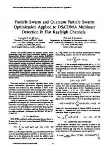
and (3, −0.3). Hence Xi = [ ai5 ai3 pci11 pci21 pci31 ]T , i = 1, 2, · · · , N . Other parameters include: N = 20, K = 0.729, c1 = c2 = 2.05, L1 = L2 = L3 = 1. Fig. 2 shows the simulation results. There are two robots forming a leader-
Mobile Robot Navigation Using Particle Swarm Optimization
Traces of robots
Traces of the first element of particles (a5)
631
Traces of the second element of particles (a3) 10 8 6
Robot 1
Value
4 Value
) (m Y
5
0
Robot 2
2 0
−5
Designed trajectory
−2 −4
−10
X (m) (a)
0
200
400
600
−6
0
400
200
600
Iteration
Iteration
(b) Fig. 2. Simulation results
follower pair to pass through field with obstacles. Fig. 2 (b) displays the evolution process of two elements, a5 and a3 , during the first 600 iterations. After 1200 iterations, all particles aggregate to a single position where a3 = 1.2917 and a5 = 0.0380, so that the desired trajectory is pd2 = 0.0380(pd1 )5 − 0.3892(pd1 )4 + 1.2917(pd1 )3 − 1.3687(pd1 )2 . Once the path is generated, a moving point on the trajectory is designed. And robot 1 is required to follow this moving point using the control strategy shown in (1) and (2).
5
Conclusions
A kind of practical technique for mobile robot navigation is proposed in this paper. The analysis and simulation demonstrate the feasibility of mobile robot navigation using PSO and ANN. Because of its low computational cost, it is easily realized in practical applications in case of real-time path planning required.
Acknowledgements This work was supported by the Research Committee of University of Macau under grant RG082/04-05S/LYM/FST.
References 1. Dyllong, E., Visioli, A.: Planning and Real-time Modifications of a Trajectory Using Spline Techniques. Robotica, 21 (2003) 475 - 482 2. Kennedy, J., Eberhart, R. C.: Particle Swarm Optimization. Proc. of IEEE Int. Conf. on Neural Network, Perth, Australia (1995) 1942-1948 3. Lewis, F. L., Yesildirek, A., Liu, K.: Multilayer Neural-Net Robot Controller with Guaranteed Tracking Performance. IEEE Trans. on Neural Networks, 7 (1996) 388-399 4. Li, Y., Chen, X.: Control and Stability Analysis on Multiple Robots. The 2nd Int. Conf. on Autonomous Robots and Agents. New Zealand (2004) 158-163 5. Clerc, M., Kennedy, J.: The Particle Swarm: Explosion, Stability, and Convergence in a Multi-dimentional Complex Space. IEEE Trans. on Evolutionary Computation. 6 (2002) 58-73