Mobility concepts for IMT-Advanced J. Bastos1, V. Monteiro1, J. Rodriguez1, R. Aguero2, D. Gomez2, Y. Fernández3, M. Peña3, F. Bader4, C. Verikoukis4, J. Herrero5, B. Cendón5, M. Raspopoulos6, S. Stavrou6, M. Cabañas7, J. Sainz7 and M. R. Santos8 1
Instituto de Telecomunicações – IT, Aveiro, Portugal 2 Universidad de Cantabria – UC, Santander, Spain 3 Tecnologías de Telecomunicaciones y de la Información – TTI, Santander, Spain 4 Centre Tecnologic de Telecomunicacions de Catalunya – CTTC, Castelldefels, Spain 5 Tecnologías, Servicios Telemáticos y Sistemas, S.A. – TST, Santander, Spain 6 Sigint Solutions Ltd – SIG, Nicosia, Cyprus 7 CREATIV-IT, Madrid, Spain 8 Wavecom – Soluções Rádio S.A., Aveiro, Portugal 1 {jbastos,vmonteiro,jonathan}@av.it.pt, 2{ramon, dgomez}@tlmat.unican.es, 3{yfernandez,mpena}@ttinorte.es, 4 {faouzi.bader,cveri}@cttc.es, 5{jherrero, bcendon}@tstsistemas.es, 6{m.raspopoulos, s.stavrou}@sigintsolutions.com, 7 {mcm,jsg}@moviquity.com,
[email protected]
Abstract. The rapid advent of different wireless technologies has posed several new challenges and requirements which current architectures are not able to appropriately deal with. The growing presence of heterogeneous access networks, together with the increasing demands from the end-users, require a re-thinking of current access selection algorithms and appropriate management mechanisms (energy-saving, robustness and spectrum efficiency, etc). All these features have gathered the interest from the scientific community, but many of available works lack from an holistic approach, which we deem necessary considering the broad range of aspects to be addressed. The “Mobility concepts for IMT-Advanced” (MOBILIA) project, belonging to the Celtic programme, specifically tackles this, by looking at the whole system (from lower layers up to services and networking). This paper presents the most remarkable findings and results obtained during the project life time. Keywords: Cross-layer, Cross-system, Heterogeneity, Cooperative schemes, Reconfigurability, MIMO, OFDM, WiMAX, LTE.
1 Introduction It goes without saying that we are being witnesses of a remarkable change on wireless communications, both from a technology perspective, but also considering additional features, such as the role of the operators, the end-users expectations, etc. In the latest years, there has been a tremendous proliferation of various wireless technologies (WiMAX, Wi-Fi, HSPA, LTE, just to name a few), thus leading to a large
heterogeneity which current communication frameworks do not correctly deal with. In parallel, new concepts and mechanisms are being proposed so as to enhance the performance and quality of service perceived by the end-users; in this group we could highlight e.g. the use of cooperative schemes, or the applicability of advanced coding procedures or the possibilities brought about by the cognitive usage of the available spectrum. One of the consequences of the scenario depicted above is that current architectures need to evolve, so as to guarantee a proper performance to the end-user; although this has gathered the attention of the scientific community, many of the recent efforts to reaching this goal lack from a holistic approach, since they do not consider all the involved layers and entities. Opposed to that, the Mobility Concepts for IMT-Advanced (MOBILIA) project, which belongs to the Celtic programme, tackles all the different layers which should cooperate in order to fulfil with the new challenges and requirements. MOBILIA has identified a set of key aspects, proposing new techniques, algorithms and mechanisms to improve current performances; these evolve from the lowest layer (PHY) up to the services themselves, and the achieved results are based both on simulation and real measurements. This paper highlights the most relevant results which have been achieved during the project lifetime, and it has been structured as follows: Section II depicts the main objectives and challenged which have been tackled during the project; Section III presents the MOBILIA architecture, which can be seen as the cornerstone of the holistic approach which has been pursued, while Section IV introduces some of the techniques which have been proposed at the various layers. Section V discusses the MOBILIA demonstration platform, which challenges the feasibility of the proposed architecture. Last, Section VI concludes the paper, advocating some items for future work.
2 MOBILIA Objectives and Challenges The advent of new challenges and requirements embrace, as has been mentioned before, all layers of the protocol stack, and heavily depend on the particularities of the involved technologies. Although MOBILIA has tackled the problem from a birds’ eye perspective, so that to be able to holistically deal with the different problems that may arise, it has also specifically addressed specific aspects, so that to carry out a more indepth analysis. Section III presents some of the more remarkable results, which derive from the selected MOBILIA objectives and challenges. The first issue which must be considered is the heterogeneity of the subjacent networking substrate. At the time of writing, access selection is usually a rather static procedure, usually requiring the end user involvement; opposed to that, it is clear that future wireless communication realms will require that the end user is automatically served with the most appropriate access, based on her own policies, the particular requirements of the service, as well as the conditions of the available resources. In this sense, it is worth highlighting the effort which is being made both by the scientific community (see e.g. [1] and the references therein for some illustrative examples) and the standardization bodies; in this latter case, we must mention the
Media Independent Handover Framework, proposed by the IEEE 802.21 working group [2]. The proposed MOBILIA architecture, which promotes the Always Best Connected paradigm (smart selection or Radio Access Technology) treats 802.21 as a nuclear part, since it is used to transport all signalling traffic. One aspect whose relevance is expected to substantially grow in the near future is energy awareness; green networking has recently emerged as a rather hot topic, and MOBILIA tackles this by means of a reconfigurable power amplifier, able to modulate its transmission power (and energy consumption) based on the knowledge about the subjacent wireless links which is promoted by the MOBILIA architecture. Two of the lower layer issues which have gathered more attention from the scientific community are: MIMO schemes and cooperative relaying procedures. Somehow, both of them are related to each other, since relaying techniques are usually modelled as virtual MIMO schemes, due to the existence of various paths between source and destination. MOBILIA has exploited both issues, proposing e.g. new algorithms to select the most appropriate coding scheme depending on link characteristics; furthermore, cooperative techniques have been proposed as a means to effectively broaden coverage area of traditional network environments. From the broad range of new technologies which will create the communication substrate, IEEE 802.16 (the so-called WiMAX) is one of the most promising ones, and furthermore, it is receiving a heavy support from the industry. Most of the techniques and procedures which it implements at the lower layers will be also part of other future wireless communications (e.g. LTE) and thus, MOBILIA decided to focus its specific research items on aspects which are mostly related to WiMAX. However, most of the results are generic enough so as to extrapolate them to other technologies. One example is the analysis of packet scheduling schemes which has been performed to be used with OFDMA-based systems.
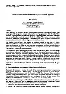
3 MOBILIA Architecture and Scenarios The MOBILIA project is trying to face the new challenges appearing with the forthcoming wireless communication scenarios, where heterogeneity is one of the most common factors. In order to identify the communication requirements, it has been defined a general use case which presents different situations (at home, driving on a highway, in the office, in a shopping centre, at the airport...) where most of the research tasks developed in the project can be identified. The story line follows a day in the life of a businessman who is moving from his home to the airport and needs to be connected to Internet during the whole journey. This user owns a Personal Area Network (PAN) which consists of a laptop (WLAN, Bluetooth) and a Smartphone (that could be a WLAN, UMTS, Bluetooth and WiMAX). The use case shows how the businessman’s PAN is able to select continuously the Best Access Point and how that decision is based on some policies previously defined, the situation of available networks and the end user requirements. Fig. 1 illustrates the architecture proposed by MOBILIA, based on the standard IEEE 802.21, to deal with the selection of access networks in highly heterogeneous environments. This figure doesn’t provide the IP mobility solution used in the project.
MIHU
APPLICATION
HoDM HoEX
HoDA
SRCIR
HoPR
MIH_NET_USER
MIH_USER
MIHF
Remote MIHF
AL ABSTRACTION MANAGEMENT LAYER
Remote AL/MIHF
ABSTRACTION LINK LAYER
MIH_LINK_USER
Link Layer
RAT 1 UMTS
RAT 2 WiFi
RAT 3 LTE
RAT 4 WiMAX
RAT N ...
Fig. 1. MOBILIA architecture.
Basically, there are three different levels: The Link Layer, which is able to receive information from different RATs and send it through different interfaces to the Abstraction Layer (AL). The Media Independent Handover Function (MIHF), which is the core element of the architecture, this entity is able to receive information from different RATs, locally or remotely, and enable a fair and technology-agnostic comparison of the characteristics of the subjacent radio technologies. Finally, the Media Independent Handover User (MIHU) which, based on the information provided by the Abstraction Layer (AL) through the MIH_USER SAP and a number of rules and policies, takes decisions on which is the most appropriate access option.
4 Major Achievements In the following sections some of the techniques that have been proposed at the various layers, inside the scope of the MOBILIA project, are presented, including some outcomes. 4.1 Reconfigurable RF Power Amplifier Current wireless communications require high peak data rates to support high quality multimedia applications. These services involve larger bandwidths and more complex modulations as OFDM for Mobile WIMAX. OFDM signals exhibit high PAPR, around 8-10 dB. Under these specifications, achieving high efficiency in power amplifier design is a demanding task to improve the battery lifetime. Power consumption in mobile terminals is a bottleneck, and because of this, different power efficiency enhancement techniques have been developed to get better performance [1] [4]. Between these techniques, Doherty amplifier topology [5] [6] [7] is a promising
candidate having the advantage of high efficiency, low cost and simple implementation. Adding reconfigurability to an efficient power amplifier design could lead to adjust to different scenarios, fitting the communication according to certain conditions as distance, number of users, quality of service, etc. Then a reconfigurable power amplifier for Mobile WiMAX applications based on Doherty amplifier topology is developing into MOBILIA project to extend the battery lifetime in the mobile terminal. Its technical requirements are: Output power: 30–31 dBm (23 dBm average output power – 8 dB PAPR). Gain: 30 dB (typical transceiver delivers around 0 dBm). Frequency band: 3400-3500 MHz (uplink band in Europe mainly). The development consists of a digital attenuator (HMC540LP3), a driver amplifier (HMC326MS8G) and a Doherty amplifier (FPD1500SOT89). To adapt the design to different power scenarios, a 4-bits digital attenuator is introduced with an attenuation range of 15 dB (1 dB LSB). Next a driver amplifier with 23 dB of gain and 23.5 dBm at 1 dB compression output power. And finally, a Doherty amplifier consists of two amplifiers, namely the carrier and the peak amplifiers. Both amplifiers are FPD1500SOT89, which has 12 dB of gain and 27.5 dBm at 1 dB compression output power. These amplifiers are connected in parallel with their outputs joined by a quarter-wave transmission line, and their inputs are joined by a 3 dB hybrid coupler. The performance of a classical Doherty amplifier can be defined in three ranges. At low power levels, the peak amplifier is shut down and the carrier amplifier is working as a conventional linear amplifier. In the second range, it works at medium power levels where the carrier amplifier is saturated and the peak amplifier takes over linear operation. And finally, both amplifiers are saturated at high power levels. A classical Doherty amplifier has the carrier amplifier in class-AB operation and the peak amplifier in class-C operation. In class-AB operation, FPD1500SOT89 is biased by applying +5 V and a negative voltage to get 200 mA. In class-C operation, the biasing point is +5 V and 10 mA approximately. After design process, a PCB layout has been manufactured and measured. Measurements were realized with different peak amplifier operation points: 10 mA (class-C) and 200 mA (class-AB) to compare results. If the peak amplifier is biased in class-AB operation is similar to have a balanced amplifier (widely used in power amplification). From Fig. 2, gain results are quite similar, 33.8 dB with Ipeak= 10 mA and 34 dB with Ipeak= 200 mA. Besides, P1dB is 30 dBm with Ipeak= 10 mA and 30.4 dBm with Ipeak= 200 mA. However the improvement in power consumption is relevant. For 23 dBm output power, PAE improves from 7.5% to 9.2% and current consumption reduces from 537 mA to 431 mA. For lower power levels, the reduction in current consumption is higher as Fig. 2b) reflects. Using this configuration, it is possible to adapt power consumption to input power levels and extend the battery lifetime in the mobile terminal maintaining analogous features in gain and power. The manufactured amplifier has 4 bits in the digital attenuator which can act as virtual control signals and adjust gain according to the configuration and contribute to save energy. Power consumption has a close relation with input power level, which can change by different factors (number of users, distance…). In Fig. 3, measured Sparameters for different attenuation values in the WiMAX reconfigurable power amplifier appear.
36
650
40
Ipeak = 10mA Ipeak = 200mA
Ipeak = 10mA Ipeak = 200mA 600
35
30
20
33
10
Idc(mA)
34
PAE(%)
Gain(dB)
550
500
450
400
32 12
14
16
18
20
22
24
26
28
350 12
0 32
30
14
16
18
20
22
24
26
28
30
32
Pout(dBm)
Pout(dBm)
b)
a)
Fig. 2. Performance of WiMAX reconfigurable power amplifier at Ipeak= 10 mA and Ipeak= 200 mA (+5 V fixed): a) Measured gain and PAE; b) Measured current consumption.
40 S11(dB) Att=0dB S21(dB) Att=0dB S22(dB) Att=0dB S11(dB) Att=7dB S21(dB) Att=7dB S22(dB) Att=7dB S11(dB) Att=15dB S21(dB) Att=15dB S22(dB) Att=15dB
30
Sparameters(dB)
20
10
0
-10
-20
-30
-40
3
3.1
3.2
3.3
3.4
3.5 Frec(Hz)
3.6
3.7
3.8
3.9
4 x 10
9
Fig. 3. Measured S-parameters of WiMAX reconfigurable power amplifier for different attenuation values (0 dB, 7 dB and 15 dB).
Input return losses are better than 12 dB and output return losses are better than 17 dB in all attenuation range from 3.4 GHz to 3.5 GHz. To sum up, WiMAX reconfigurable power amplifier for Mobile WiMAX applications presents better results using a Doherty amplifier topology and also is able to adapt to different scenarios fitting properly the communication. Final development and measurements will be carried out till the end of the project. Besides, other Doherty topologies will be studied apart from Classical Doherty amplifier topology. 4.2 MIMO and Spatial Adaptation Apart from the increase of the capacity or the reliability by any of widely used precoding techniques the simplest precoding technique is to select which antenna(s) should be used according to any optimization criterion. The reduction of the number
s0 s1 …,b1,b0
sQ-1
Linear Dispersion coding xM-1
Transmit Antenna Selection
···
Mapping (Z-QAM)
x0 x1
···
of antennas reduces the array gain, however when the channel experiencing a deep fade, the capacity loss by not using such antenna is minimal. In consequence, antenna selection at both transmitter and receiver helps in reducing the implementation costs while retaining most of the benefits of MIMO technology. The performance analysis of Transmit Antenna Selection with Linear Dispersion Code (LDC) Selection [8] (TACS) is subject of researches in MOBILIA project [9]. Proposed spatial link adaptation (see Fig. 4) is evaluated under low mobility environments concluding that maximum spatial diversity (SD) is achieved as well as a smooth transition between codes with low spatial multiplexing (SM) rate and high SD, to codes with high multiplexing rate but low diversity order in order to maximize the overall system throughput. The MIMO system model considering antenna selection is depicted in Fig. 4, where M and N are the number of transmitter and receiver RF chains respectively, whereas the available antennas are referred by Ma and Na for transmitter and receiver
SpaceTime decoding
Demapping ... b2 , b1 , b0 (Z-QAM) Channel estimation
LDCs Codebook
Ma N TACS
Feedback channel, bf [bits]
Fig. 4. TACS spatial adaptation scheme and integration into the transmission scheme.
respectively (with MMa, NNa). It has been emphasized that the LDC framework allows expressing all the linear STBCs with the same structure. The first linear STBC proposed follows the Bell-Labs Layered Space Time (BLAST) architecture [10] [11]. The SM scheme also referred as Vertical-BLAST, is a full rate code (rs=M) that consists of transmitting independent data streams on each transmit antenna. A layer is considered as the stream of data transmitted from each transmit antenna, hence each layer experiences a different channel. Using a linear MMSE receiver, the Effective Signal to Interference and Noise Ratio (ESINR) per each symbol q is given by ESINRq MMSE Η
1
M Η Η 2 I 2Q q ,q H
1
1 ,
(1)
where X-1q,q refers to the (q,q) element from X-1, and is the average Signal to Noise Ratio (SNR). Furthermore, if the mapping applied to the symbols follows a 2 n-QAM constellation, the average pair wise error probability per stream applying the Nearest Neighbor Union Bound can be obtained as follows d 2 n , Pe,q 1 1 N e n Q ESINRq H min 2
(2)
where Q(x)=0.5erfc(x/21/2), d2min is the squared minimum distance between any two points of the constellation (with unitary average transmission power), and Ne is the
average number of nearest neighbors constellation points where ESINRmin=min(ESINR0,…, ESINRQ-1) [12]. The optimization is performed in order to maximize the system throughput considering a certain QoS. In that case, the problem is formulated as follows
max
LDCi , pi , MCS j
min R 1 BLER ESINRq q
s.t.: BLER ,
(3)
where j means the Modulation and Coding Scheme (MCS) index that maximizes the spectral efficiency for the specific channel state subject to a maximum Block Error Rate (BLER). Actually, the selection of the optimum MCS is carried out assuming that the ESNR is the SNR that would be obtained at the receiver in case having an Additive White Gaussian Noise channel. Under that assumption, there is a direct mapping between each MCS and the obtained BLER for each ESNR. For the TACS evaluation, the downlink a WiMAX TDD system has been used [13]. The number of available transmitter antennas are Ma=2 whereas the number of receiver antennas is fixed to N=2. The performance of the TACS adaptation scheme in case the throughput is maximized (see eq. (3)) is analyzed. The basic sets of LDC codes used for the study are: the SIMO code using Maximum Ratio Combiner (MRC), the Alamouti code (referred as G2 in the plots), the BLAST-like codes with M=2 (referred as SM in the plots) and the Golden code (GC). The codeword length for all the codes is T=2. Moreover, for the SM case two types of encoding have been tested named vertical encoding (SM-VE) and horizontal encoding (SM-HE). The MMSE receiver in Fig. 5 and Fig. 6 show that at SNRs < 13 dB, the SIMO and Alamouti schemes achieved the highest spectral efficiencies. However, as the SNR is increased the codes with higher multiplexing capacity (e.g. the SM and the GC) are preferred. We also observed that the SM with VE implies a loss of around 2 dB compared to the Golden code, but when HE is used, the Golden code is around 0.5 dB
Fig. 5. Spectral efficiency under TACS with Ma=2, N=2, ACM and MMSE receiver for a correlated MIMO Rayleigh channel.
Fig. 6. LDC selection statistics under TACS with Ma=2, N=2, adaptive MCS and MMSE receiver for an uncorrelated MIMO Rayleigh channel.
worse than the SM-HE. The TACS behaviour the statistics of LDC selection as a function of the average SNR are plotted in Fig. 6. We can clearly appreciate that at low SNR the preferred scheme is SIMO where all the power is concentrated in the best antenna, while as the SNR is increased full rate codes (Q=M) are more selected since they allow to use lower size constellations. Comparing SM-VE with SM-HE, we can observe that SM-HE is able to exploit the stream’s diversity and hence achieves a higher spectral efficiency than with the GC. At SNR=12 dB, the SM with HE is the scheme selected for most frames, even more than SIMO. Obtained results shown that in case of linear receivers (e.g. MMSE) the TACS scheme with AMC achieves a noticeable SNR gain (up to 3 dB) in a large SNR margin (SNR from 6 to 18 dB), and also is a good technique to achieve a smooth transition between diversity and multiplexing. 4.3 Cooperative MIMO Capacity In this section we present the potential advantages in terms of capacity improvements of cooperative MIMO systems, also known as virtual MIMO or distributed MIMO (D-MIMO). In a Multiple-Input-Multiple-Output (MIMO) system, more than one antenna element is available at each end of the communication link [14]. The use of multiple antennas at each side of the communication link exploits the rich scattering channel to create multiplicity of parallel radio links over the same radio band and therefore increase the data rate through multiplexing or increase reliability through the increased antenna diversity gain. Unfortunately the enormous theoretical gain predicted in conventional MIMO (C-MIMO) cannot be achieved in realistic environments because of the insufficient antenna spacing and the small angular spread between the contributions arriving on the different antenna elements which increases the correlation between them.. Using Distributed MIMO (D-MIMO) which can be realized when a multi-antenna mobile terminal receives contributions from multiple base stations or from multiple other users in an ad-hoc manner the spatial correlation can be increased as the various contributions will be arriving on the terminal using different (uncorrelated) paths leading to higher capacity gains.. This approach though requires high degree of cooperation between the terminals and for this reason it is usually referred as cooperative MIMO or cooperative relaying. This can be accomplished through suitably designed protocols [15-19]. To prove the principle of improved capacity in D-MIMO cases a Manhattan-like scenario has been used as shown in Fig. 7. It is a 625 m by 625 m area consisting of 20 m x 20 m equally spaced (by 10 m) buildings assumed to be made of concrete. Thirteen transmitting isotropic antennas 2.4 GHz have been defined (placed at 20 m above the ground), and various combinations of them have been used to investigate SISO, C-MIMO (2x2 and 4x4) and D-MIMO (2x2 and 4x4) capacity. To allow for CMIMO investigations, TX1 and TX10 have been defined as a 2x2 antenna array as shown in Fig. 8 with the individual antenna elements separated by half a wavelength. One receiver route has been used for the investigations and is depicted in Fig. 7 consisting of 5986 receivers equally spaced by 2 cm (less than half wavelength) in order to be able to capture fast fading effects. Every receiver location it is assumed to
consist of an array of 4 isotropic antenna elements arranged at straight line at a height 1.5 m. The noise figure of each receiver is assumed to be 3 dBm. 3DTrueEM has been used to calculate the channel matrices which will become the input to the MIMO capacity formulation presented in this section. The transmit power was set to 33 dBm (BW=22 MHz). The ray tracing simulator considers unlimited number of 3D reflections and transmissions and one UTD diffraction. Additive Gaussian White Noise (AGWN) was assumed. 3DTruEM is a 3D Ray Tracing Simulator developed by Sigint Solutions. Its calculation engine uses a ray tracing algorithm offering improved accuracy and efficiency utilizing the 3D electromagnetic formulation of reflection, refraction and diffraction based on the Universal Theory of Diffraction (UTD), to provide accurate site-specific radio propagation predictions for a wide range of wireless communication systems. As said, various cases have been simulated in order to investigate the potential benefit in capacity D-MIMO Environments. These cases have included both Line of Sight (LoS) and Non Line of Sight (NLoS) situations along the estimation route depicted in Fig. 7 for both CMIMO and D-MIMO. The 4x4 and 2x2 C-MIMO and D-MIMO cases have been also compared to the standard SISO case. Fig. 9 and Fig. 10 below demonstrate some indicative results of this investigation. It can be seen that D-MIMO behaves as good as C-MIMO in terms of capacity in LoS cases but has but has more significant improvement in NLoS situations. Although the absolute capacity in NLoS is less compared to the LoS (this is due to the fact that the received signal to noise ratio is higher in LoS) the increase in capacity in cooperative MIMO is higher in NLoS and this is due to the fact that the various contributions arriving on the terminal follow completely different (uncorrelated) paths.
λ/2
λ/2
TX1,1
TX1,3
Fig. 7. Manhattan scenario for MIMO capacity investigations
TX1,3
TX1,4
Fig. 8. Transmitter TX1 for conventional MIMO investigation
Fig. 9. Conventional vs. Cooperative MIMO for LoS case
Fig. 10. Conventional vs. Cooperative MIMO for NLoS case
4.4 Cross-Layer design between MAC and PHY layers in WiMAX A flexible DRA architecture framework, specifically designed for a cross-layer-based architecture, under Mobile WiMAX network, is proposed here jointly with a variation of the original opportunistic (in channel access) Maximum C/I scheduler algorithm, which overcomes its limitations. The Dynamic Resource Allocator (DRA) architecture is illustrated in Fig. 11 and comprises the following modules: (i) Packet Scheduler, (ii) Resource Allocator, (iii) Hybrid Automatic Repeat Request (HARQ) and (iv) Link Adaptation (Adaptive Modulation and Coding – AMC). In each transmission time interval (TTI) the DRA allocates radio resources in the TDD frame, according to the priority list metrics outputted from the scheduler. Whenever a user is selected for transmission, the DRA withdraws the required data bits from the respective queue, in order to fill up a Medium Access Control – Protocol
Fig. 11. Dynamic Resource Allocator architecture with constituent modules.
Data Unit (MAC-PDU) packet which occupies the space corresponding to a data burst in the resource space of the TDD frame, using padding bits to fill the remaining space if necessary. The DRA is implemented and the performance is evaluated using three known schedulers: Max C/I, Max C/I over Average C/I and Round Robin. Using the Channel Quality Indicator (CQI) in frame n, the ith user from the set of K users is selected according each scheduler, based in: Max C/I: (4) k CI n arg max CQI i (n), n 0,1,2,... i1,...,K
Max C/I over Average C/I:
k CI n arg max
CQI i (n)
i1,...,K CQI
, n 0,1,2,...
(5)
i ( n)
Round Robin: Simply performs a fair round multiplexing of users in each frame. Fig. 12 shows the plot of the cumulative distribution functions for the user service throughput of all three schedulers. Results are for pedestrian users, with video downloading service. Results show about 65% of the users not serviced with the CI scheduler. Among the three schedulers the Averaged CI presents the best performance mainly for users in the edge of the cell. The users closer to the base station produce the same service throughput of roughly 60 kbps. Ongoing investigations focus on throughput improvement by the inclusion of Space Division Multiple Access (SDMA) in the presented DRA architecture.
Fig. 12. CDF of User Service Throughput and Average Packet Delay for NRTV users
with PedB, 3 km/h. 4.5 RAT Selection Algorithm for 802.11e and HSDPA An algorithm for selecting the most suitable Radio Access Technology (RAT) is proposed with the objective of balancing the load in critical cell load situations. The rationale behind the algorithm is the following: a preferable RAT is selected by default to handle a service, assuming in this case that the service traffic is flexible and can be handled by more than one RAT. Studies on cross-layer show that concave and convex functions are more suitable when flexibility and limited conditions are required [20] [21]. An empirical algorithm for load balancing among cells of different RATs is proposed when a new call is requested. The algorithm is targeted to flexible traffic and imposes certain flexibility on the system, meaning that the service can be held by each RAT. The algorithm for the suitability (S) is expressed by the following equation: if L(cell i , j ) LTh j 1 2 S ( L(cell i , j )) 1 L(cell i , j ) if L(cell i , j ) LTh j 1 LTh j
(6)
The simulations were performed in a scenario based on a co-covered HSDPA and Wi-Fi indoor area with parameters detailed in Tab. 1, assuming high-priority NearReal-Time-Video traffic at 64 kbps. The performance with the Common Radio Resource Management (CRRM) is compared to HSDPA stand-alone. In Fig. 13 the QoS throughput outage probability is shown when CRRM is used with HSDPA/Wi-Fi coexistence. Results show that up to 42 users were supported against 29 users for the HSDPA case only, resulting in a gain of 45% on outage probability with the CRRM (intelligently adapted algorithm) over HSDPA alone. Ongoing work focuses on the algorithm enhancement targeting also energy efficiency.
Tab. 1. Main HSDPA and Wi-Fi simulation parameters Parameter
HSDPA
Wi-Fi
Mode
TDD (Tx mode)
EDCA
Load threshold
0.6
0.6
Scheduler
MaxCI
Round-Robin
Link Adaptation
BLER 10%
-
Propagation model
3GPP indoor + FF
ITU 2GHz
Cell type
Omni
Omni
Num. HS- PDSCH
15
-
CRRM - Outage probability
1.2 1 0.8 0.6 0.4 0.2
CRRM QoS Througuput HSDPA QoS Throughput
0 26
28
30
32
34
36
38
40
42
NRTV users
Fig. 13. HSDPA normalized load according the number of users (CRRM vs. HSDPA alone).
5 MOBILIA Demonstrator Despite the strong related research activity, there is still a need to assess the feasibility of heterogeneous access selection architectures over real platforms. In this sense, the MOBILIA demonstrator aims at illustrating the main objectives of the architecture presented in Section III, considering the limitations of the available technology. The scenario which will be used is shown in Fig. 14. As can be seen the demonstrator is composed by a mobile device, two different access points and a server which has two main roles: an access broker (with an overall network view, able to manage resources) and a streaming server. The demonstrator is carried out using off-the-shelf IEEE 802.11 technology, rather than real heterogeneous technologies due to the various restrictions which were found to integrate the MOBILIA components with other wireless technologies, like e.g. WiMAX (the most relevant reasons are: lack of proper drivers and the limitations imposed by the implementation possibilities at the network access elements). We
192.168.3.1/24
WLAN 1
192.168.4.1/24
192.168.4.2
192.168.3.64
192.168.1.64
USER
SERVER WLAN 2
192.168.1.1/24
Fig. 14. Generic scenario MOBILIA demonstrator.
opted for using orthogonal IEEE 802.11 channels (and therefore, the heterogeneity is correctly emulated) and we took advantage from the madwifi drivers, so as to incorporate the MOBILIA developments at the access points (which were actually implemented on traditional laptops). The access broker retrieves all the QoS information from the access points and monitor all these parameters in order to be able to send handover messages to the mobile nodes upon any event which might require such an action (e.g. if it detects that the number of users of any access point is high or if the QoS parameters are low to keep a currently ongoing connection). The mobile device is emulated with a laptop comprising two interfaces, and therefore it is able to connect to two different access points, taking into account the information received from both the access broker and the interfaces themselves (by means of the MOBILIA architecture). Once the mobile node detects that the link quality of the currently serving network is decreasing or it receives a message from the access broker instructing to handover to another network, the mobile node starts a handover procedure, which happens seamlessly. In this case the SCTP is used as the mobility solution. For the demonstrator, a streaming session starts and two illustrative use cases are shown: Mobile node is connected to one access point and the lower layers (LL) detects that the quality of the link goes below a predefined threshold. As a consequence, various MIH messages will be exchanged and the HoDM finally will take the decision to handover to another access element, in order to keep the same quality of service for the video session. In parallel, HoDM notifies the mobility solution (SCTP) to execute the corresponding change; overall, the process might be seen as a “make-before-break” handover. In this sense, the second interface starts negotiating the connection with the other access point and only when the connection is made, the SCTP solution establishes the new connection flow.
In the second use case, the handover is initiated by the network. The currently serving access element detects an overload situation, and informs the access broker. This entity (having an overall vision of the whole network topology) will send a message to the handover decision manager of the mobile node to start the handover process, which will look pretty much the same as the previously described one.
6 Conclusion The work presented in this paper shows a general overview of the research investigations being carried out in the scope of advanced techniques targeting mobility in future wireless communication systems, addressed in the MOBILIA project. These investigations already produced some significant results, as presented here, namely focusing WiMAX in particular, and broadband wireless communications in general. Moreover, the heterogeneous architecture that is considered reflects the ultimate future wireless communications market, which is on the edge of an exponential growth, and since standardization on this matter is just starting, now is the moment to further develop enabling technologies for such advanced techniques.
Acknowledgement This work has been performed in the framework of the MOBILIA project (CP5-016) under the Eureka Celtic Framework. The Spanish partners would like to thank the Spanish government for the funding of this project, through the Avanza I+D programme (TSI-020400-2008-82). The Portuguese partners would like to thank the Portuguese government for the funding of the MOBILIA project, through the QREN Framework – PO Centro (project n. 5555).
References 1. Giupponi, L., Agusti, R., Perez-Romero, J., Sallent, O.: Joint radio resource management algorithm for multi-RAT networks. In: Global Telecommunications Conference, 2005. GLOBECOM ’05. IEEE. vol. 6 (2005) 2. Taniuchi, K., Ohba, Y., Fajardo, V., Das, S., Tauil, M., Cheng, Y.H., Dutta, A., Baker, D., Yajnik, M., Famolari, D.: IEEE 802.21: Media independent handover: Features, applicability, and realization. Communications Magazine, IEEE 47(1), 112 –120 (2009) 3. Cripps, S.C.: Advanced Techniques in RF Power Amplifier Design. Artech House, Norwood (2002). 4. Kenington, P.B.: High-linearity RF Amplifier Design. Artech House, Norwood (2000) 5. Kim, J., Cha, J., Kim, I., Noh, J., Park, C., Kim, B.: Advanced Design Methods of Doherty Amplifier for Wide Bandwidth, High Efficiency Base Station Power Amplifiers. 35th European Microwave Conference, Paris, nº2 (2005) 6. Chen, X., Guo, Y., Shi, X.: A High Linearity and Efficiency Doherty Power Amplifier for Retrodirective Communication. PIERS Online, vol. 4, no 2, pp. 151--156 (2008)
7. Jin, S., Zhou, J., Zhang, L., Hong, W.: A low cost 1 Watt Doherty power amplifier for WLAN and WIMAX applications. Progress in electromagnetics research symposium, pp. 555-558. Beijing (2009) 8. Gohary, R., Davidson, T.: Design of Linear Dispersion Codes: Asymptotic Guidelines and Their Implementation. In: Proc. IEEE Transactions on Wireless Communications, vol. 4, no. 6, pp. 2892-2906 (2005) 9. Mobility Concepts for IMT-Advanced-MOBILIA project , http://www.MOBILIAproject.org/ 10. Gutierrez, I., Bader, F., Mourad, A.: Joint Transmit Antenna and Space-Time Coding Selection for WiMAX MIMO System. In: Proc. of 20th IEEE Personal, Indoor and Mobile Radio Communications Symposium 2009 (IEEE PIMRC’09). Tokyo, Japan (2009) 11. Heath, R. W., Love, D. J.: Multimode Antenna Selection for Spatial Multiplexing Systems with Linear Receivers. In: IEEE Transactions on Signal Processing, vol. 53, no. 8, pp. 3042-3056 (2005) 12. Foschini, G. J.: Layered space-time architecture for wireless communications in a fading environment when using multiple antennas. In: Bell Lab Tech. J. vol. 1., no. 2 (1996) 13. IEEE Standard for Local and Metropolitan Area Networks, Part 16: Air Interface for Fixed and Mobile Broadband Wireless Access Systems, IEEE Std 802.16e™-2005 (2006) 14. Foschini, G. J., Gans, M. J.: On Limits of Wireless Communications in a Fading Environment when Using Multiple Antennas. In: Wireless Personal Communications, pp.311-335 (1998) 15. Hunter, T. E., Nosrantinia, A.: Cooperative diversity through coding. In: IEEE Proc. ISIT, , pp. 220, Lausanne, Switzerland (2002) 16. Laneman, J. N., Wornell, G. W.: Distributed space-time-coded protocols for exploiting cooperative diversity in wireless networks. In: IEEE Trans. Inform. Theory, vol. 49, no. 10, pp. 2415-2425 (2003) 17. Sendonaris, A., Ekrip, E., Aazahang, B.: User Cooperation diversity – Part I: System Description. In: IEEE Trans. Commun., vol. 51, no. 11, pp. 1927-1938 (2003) 18. Sendonaris, A., Ekrip, E., Aazahang, B.: User Cooperation diversity – Part II: Implementation aspects and performance analysis. In: IEEE Trans. Commun., vol. 51, no. 11, pp. 1939-1948 (2003) 19. Stefanov, A., Erkip, E.: Cooperative coding for wireless networks. In: Proc. Intern. Workshop on Mobile and Wireless Commun. Networks, pp. 273-277, Stockholm, Sweden (2002) 20. Ryu, S., Ryu, B.-H., Seo, H., Shin, M., Park, S.: Wireless packet scheduling algorithm for OFDMA system based on time-utility and channel state. In: ETRI Journal, vol. 27, no. 6 (2006) 21. Hosein P.: On the optimal scheduling of uplink resources in OFDMA-based wireless networks. In: Proc. of EW 2006 - 12th European Wireless Conference, Athens, Greece (2006)